made for robots
TRANSCRIPT

Made for Robots.
Solutions for: ABB • FANUC • KUKA • YASKAWA/MOTOMAN
The Stand-Alone Torch Weld Package: DCT power source • Weld process controller • Robot interface • Wire feeder• Wire guidance • Cable bundle • Control cable •
Torch system • Torch necks • Consumables
For stationary applications
Dokument-Nr.: DOC-0185EN | Revision: SKSde.06DEZ19.ms.bp.v2.0.0
Weld Package Stand-alone torch
Simpleintegration

Fixture
9
4
6
7
SKS Weld Package: System design
This brochure contains information about the SKS Weld Package, the torch system Stand-Alone Torch, as well as consumables and spare parts. There are various features of the welding machine components and torch systems available depending on the robot system and the welding task. The Stand-Alone Torch Weld Package can be used with common industrial robots, such as ABB, FANUC, KUKA and YASKAWA/MOTOMAN.
DCT power source
Robot interface
Wire feeder
Wire guidance
Cable bundle
Torch system Stand-Alone Torch
Ground cable
Torch necks/Consumables
Control cable
Weld process controller + Software
For stationary installations.
1
5
3
7
10
2
6
9
4
8
Gas nozzles11
TCP dimensions12

1
2
3
8
Processes: MIG/MAG (GMAW), Pulse, MIG Brazing
Wire materials: High-alloy steels, low-alloy steels, aluminum and copper alloys,
nickel-based materials
Wire diameter: 0.8-1.6 mm
Max. power: 420 A - 60 % duty cycle/40 °C, air-cooled
The complete SKS Stand-Alone Torch Weld Package is designedfor the following welding processes, materials and power range:

Power source LSQ5
Power source
LSQ5 power source with Direct Control Technology DCT
The LSQ5 ensures the optimum arc energy. It uniquely adjusts to different weld processes. Unlike conventional power sources with inverter technology, the LSQ5 with Direct Control Technology controls its switching transistors without any fixed clock frequency according to the needs of the weld process. Without any delay, the energy needed for the process is provided instantly. The flexible fine tuning is done by a central processor. The CPU continuously analyzes the weld process and current/voltage values on the basis of data obtained and optimally drives the switching transistors of the power section. This results in an extremely high efficiency and a low temperature development. The power source can be configured with only two buttons and four LED indicators. For world-wide usage, voltages can be configured without opening the power source.
Overview of power sourcesDESCRIPTION PART-NO.LSQ5 77-1185-00LSQ5-CCC 77-1185-60
The main benefits are: • DCT provides a speed regulation up to ten times higher compared to conventional inverter technology. This leads to excellent control behavior and shorter response times.• The weld properties are substantially improved. Software replaces hardware: Fewer components also increase the reliability in continuous operation.
Weld process controller Q6pw and Q4
The perfect solution for local administration – the weld process controllers Q6pw and Q4 provide all basic functions of the Q80. The controllers can be administrated over the USB port with the Q8TOOL4 software. As a small and compact solution for the cost-optimized application, the Q4 is integrated into the power sources LSQ3 or LSQ5.• Processes/features: MIG/MAG (GMAW), I-Pulse, U-Pulse, KF-Pulse• Programs: 186• General functions: Display and saving of readings, alarms• Monitoring functions: Weld current monitoring, auto compensation, arc and ignition monitoring,motor current, gas and water monitoring• Ports: RS232 (Q6pw only), SPW-Bus (Q6pw only), USB
Overview weld process controllerDESCRIPTION PART-NO.Q6pw 77-7230-00Q4/LSQ5 77-1185-20Q4/LSQ5-CCC 77-1185-21
Weld process controller Q4Weld process controller Q4 as integratedsolution into the power source
Weld process controller Q6pw
Weld process controller2
Please note:
The Q4 weld process ontroller is integrated into the front of the power source and is delivered with the power source.
Robot interface3
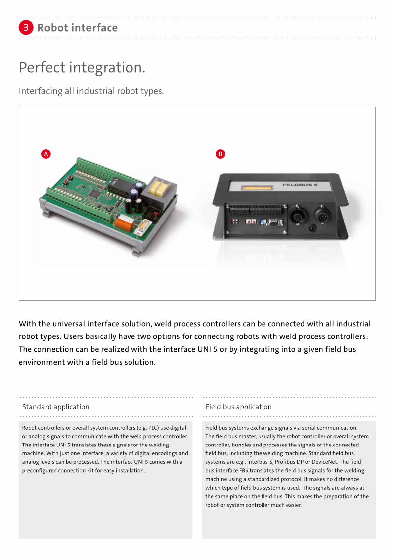
Perfect integration.Interfacing all industrial robot types.
With the universal interface solution, weld process controllers can be connected with all industrial robot types. Users basically have two options for connecting robots with weld process controllers: The connection can be realized with the interface UNI 5 or by integrating into a given field bus environment with a field bus solution.
Robot controllers or overall system controllers (e.g. PLC) use digital or analog signals to communicate with the weld process controller. The interface UNI 5 translates these signals for the welding machine. With just one interface, a variety of digital encodings and analog levels can be processed. The interface UNI 5 comes with a preconfigured connection kit for easy installation.
Field bus systems exchange signals via serial communication. The field bus master, usually the robot controller or overall system controller, bundles and processes the signals of the connected field bus, including the welding machine. Standard field bus systems are e.g., Interbus-S, Profibus DP or DeviceNet. The field bus interface FB5 translates the field bus signals for the welding machine using a standardized protocol. It makes no difference which type of field bus system is used. The signals are always at the same place on the field bus. This makes the preparation of the robot or system controller much easier.
Standard application Field bus application
A B
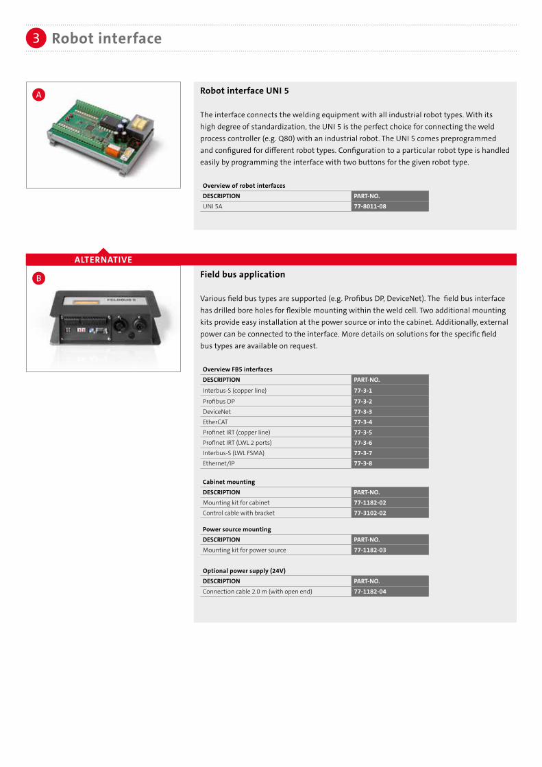
Robot interface UNI 5
The interface connects the welding equipment with all industrial robot types. With its high degree of standardization, the UNI 5 is the perfect choice for connecting the weld process controller (e.g. Q80) with an industrial robot. The UNI 5 comes preprogrammed and configured for different robot types. Configuration to a particular robot type is handled easily by programming the interface with two buttons for the given robot type.
Overview of robot interfacesDESCRIPTION PART-NO.UNI 5A 77-8011-08
Field bus application
Various field bus types are supported (e.g. Profibus DP, DeviceNet). The field bus interface has drilled bore holes for flexible mounting within the weld cell. Two additional mounting kits provide easy installation at the power source or into the cabinet. Additionally, external power can be connected to the interface. More details on solutions for the specific field bus types are available on request.
Overview FB5 interfacesDESCRIPTION PART-NO.
Interbus-S (copper line) 77-3-1
Profibus DP 77-3-2DeviceNet 77-3-3EtherCAT 77-3-4Profinet IRT (copper line) 77-3-5Profinet IRT (LWL 2 ports) 77-3-6Interbus-S (LWL FSMA) 77-3-7Ethernet/IP 77-3-8
Cabinet mountingDESCRIPTION PART-NO.Mounting kit for cabinet 77-1182-02Control cable with bracket 77-3102-02
Power source mountingDESCRIPTION PART-NO.Mounting kit for power source 77-1182-03
Optional power supply (24V)DESCRIPTION PART-NO.Connection cable 2.0 m (with open end) 77-1182-04
Robot interface3
ALTERNATIVE
A
B

Power Feeder PF5
Modern motor, gear and control technology provide a strong performance and highest possible precision. The robust plastic housing is electrically insulated. As a "lightweight" the PF5 is the perfect choice for the new generation of robots with inner cable dress.The industrial proven Power Feeder PF5 is available with an additional monitoring functionality: an integrated gas-flow sensor. The weld process controller displays the gas flow values, and can also be triggered to an alarm, in case of a non-defined gas flow rate.
Smaller and with less weight accompanied by improved efficiency over conventional wire feeders the PF5 goes along with the steady development of arc welding robots.
PF5 with integrated gas flow sensor
ALTERNATIVE
Wire feeder4
Strong, lightweight and precise.The PF5 wire feeder.
Overview PF5DESCRIPTION PART-NO.PF5 L 10-2-8PF5 L with integrated gas flow sensor 10-2-108
Technical dataWeight 3.8 kgMotor 70WWire feeding speed 2.5 - 25 m/minRoll diameter 0.8 - 1.6 mm
Shielding Gas Saver
The benefit of the shielding gas saver is its pre-regulated working pressure of 1.2 bar / 17 psi (common 4.5 bar / 65 psi). Therefore the ram pressure is reduced, i.e. there are key benefits of the shielding gas saver at ignition of the welding torch and an improved gas saving. The shielding gas saver ensures a constant gas flow during the welding task.
Shielding Gas SaverDESCRIPTION PART-NO.Shielding Gas Saver 93-62-5

Drive roll for wire feeder
For wire diameters 0.8 - 1.6 mm and groove-types (V-groove for steel and U-groove for aluminum wires)
Wire feeder brackets
Wire feeder bracket for PF5 with holes and screws for installation
Overview of wire feeder bracketsDESCRIPTION PART-NO.Bracket for stationary applications 14-1-16
Wire feeder4
Center guides
Available in two versions: For steel or aluminum wires
Overview of center guidesDESCRIPTION PART-NO.Wire-ø 0.8 - 1.6 mm for steel wire 12-2-1-15Wire-ø 1.0 - 1.6 mm for aluminum 12-2-1-19
Overview of four roller drive rollsDESCRIPTION PART-NO.Wire-ø 0.8 mm, V-groove 12-2-3-08Wire-ø 0.9 mm, V-groove 12-2-3-09Wire-ø 1.0 mm, V-groove 12-2-3-10Wire-ø 1.2 mm, V-groove 12-2-3-12
Wire-ø 1.4 mm, V-groove 12-2-3-14Wire-ø 1.6 mm, V-groove 12-2-3-16Wire-ø 1.2 mm, U-groove 12-2-3-112Wire-ø 1.6 mm, U-groove 12-2-3-116
Pressure roll
Pressure roll for wire feeder.
Pressure rollDESCRIPTION PART-NO.Pressure roll 12-2-3-0Locating bolt for pressure roll 12-13-5Pressure roll for aluminum wire, U-groove 1.2 mm 12-2-5-112Pressure roll for aluminum wire, U-groove 1.6 mm 12-2-5-116Locating bolt for pressure roll U-groove 12-2-1-23Knurled screw for pressure roll U-groove 12-2-1-24
Please note:
Two drive rolls are needed per system.
Please note:
Two pressure rolls and two locating bolts are needed per system.

Wire guidance polymer for aluminum wires5
With the new SKS polymer guidance, the high efficiency of the whole system extends up to the drum.
Advantages of polymer wire guidance• Extraordinary good glide properties reduces motor load• Minimized abrasive wear and reduced dirt in wire feeder and torch system• Lightweight design and a high inherent stability for easy installation• Length can be freely chosen by the customer• Cost optimized exchange: only the polymer conduit must be changed, connectors are reuseable.• Optimized materials for longer life and reduced downtimes
Please note:
Furhter information can be found in our brochure "Wire guidance" (DOC-0193EN).
Wire inlet body with quick
coupling
Connection nipple for polymer conduit
Polymer conduit
Drum connector with ceramic inlay
1
4
2
3
4
2
3
1
Wire inlet body, Connection nipple, Polymer conduit and Connection for wire drum
Wire inlet body with quick couplingDESCRIPTION PART-NO.Wire Inlet body with quick lock and polymeric inlet 10-2-0-63Polymeric inlet (spare part) 10-2-0-63-2Inset for aluminum wire 10-2-0-57-3
Connection nipple for polymer conduit DESCRIPTION PART-NO.Connection nipple 44-40-3
Polymer wire conduitDESCRIPTION PART-NO.Polymer wire conduit, blue, per meter 44-9-1
Connection for wire drumDESCRIPTION PART-NO.Drum connector with ceramic inlay 44-40-1
OPTIONDESCRIPTION PART-NO.Strain-Relief for wire guidance 14-10-6
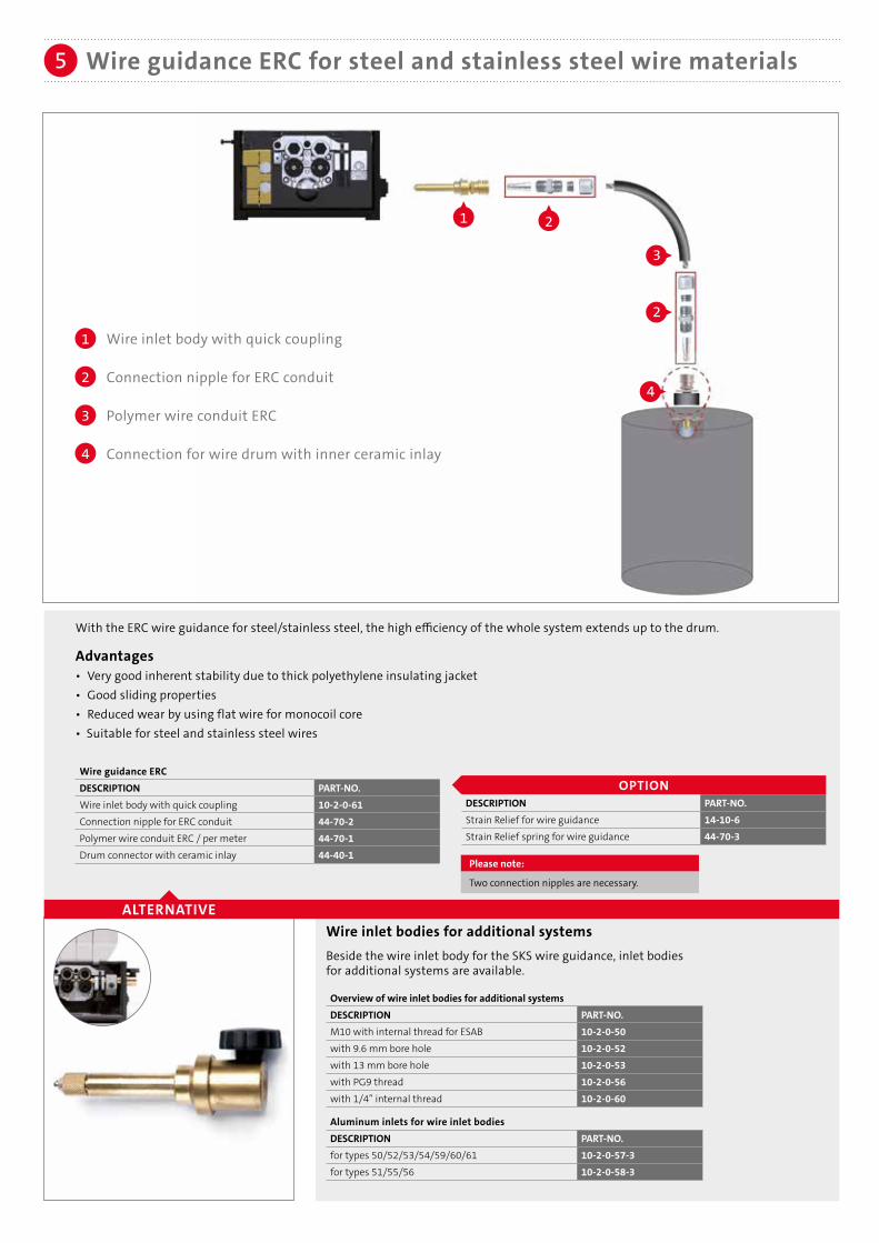
Wire guidance ERC for steel and stainless steel wire materials5
Wire inlet bodies for additional systemsBeside the wire inlet body for the SKS wire guidance, inlet bodiesfor additional systems are available.
Overview of wire inlet bodies for additional systemsDESCRIPTION PART-NO.M10 with internal thread for ESAB 10-2-0-50with 9.6 mm bore hole 10-2-0-52with 13 mm bore hole 10-2-0-53with PG9 thread 10-2-0-56with 1/4” internal thread 10-2-0-60
Aluminum inlets for wire inlet bodiesDESCRIPTION PART-NO.for types 50/52/53/54/59/60/61 10-2-0-57-3for types 51/55/56 10-2-0-58-3
ALTERNATIVE
With the ERC wire guidance for steel/stainless steel, the high efficiency of the whole system extends up to the drum.
Advantages• Very good inherent stability due to thick polyethylene insulating jacket• Good sliding properties• Reduced wear by using flat wire for monocoil core• Suitable for steel and stainless steel wires
Wire guidance ERCDESCRIPTION PART-NO.Wire inlet body with quick coupling 10-2-0-61Connection nipple for ERC conduit 44-70-2Polymer wire conduit ERC / per meter 44-70-1 Drum connector with ceramic inlay 44-40-1
1
4
2
3
1 2
3
2
4
Wire inlet body with quick coupling
Connection nipple for ERC conduit
Polymer wire conduit ERC
Connection for wire drum with inner ceramic inlay
Please note:
Two connection nipples are necessary.
OPTIONDESCRIPTION PART-NO.Strain Relief for wire guidance 14-10-6Strain Relief spring for wire guidance 44-70-3

Cable bundles: Power source to wire feeder PF5
Coaxial power cable 72 mm2 with internal gas flow, control cable L700, disconnect cable, corrugated tube and cable holder. Air-cooled version.
Overview of cable bundlesLength PART-NO.5 m 20-40-57 m 20-40-710 m 20-40-10
Cable bundles6
Ground cable with 70 mm2 connector and cable plug
Cables with larger diameters are available on request
Overview of ground cablesLENGTH PART-NO.6 m 22807810610 m 228078100
Ground cable7
Please note:
Further lengths available on request
Please note:
Further lengths available on request

The advantages of a system concept are revealed by its details: One standard control cable (L700) connects all system components (power source, robot interface, weld process controller and wire feeder) within the welding system. The system is expandable: Other components can be integrated at any time into an existing system. New devices are automatically detected.
Control cable: L700/SPW-bus
Standard control cable to connect the components:Weld process controller, power source, robot interface, wire feeder.
Overview of control cablesLENGTH PART-NO.0.5 m 5410310501 m 5410310012 m 5410310023 m 5410310035 m 5410310057 m 54103100710 m 54103100012 m 54103101215 m 541031015
Control cable8
PLUG & PLAY: CONTROL CABLE L700
POWER SOURCE ROBOT INTERFACE WELD PROCESS CONTROLLER WIRE FEEDER
Please note:
For the Stand-Alone Torch system three control cables are needed. One control cable is already included in the cable bundle.
Please note:
Further lengths available on request
Single wire torch holder for fixtures
Precision single wire torch holder with the industrial proven quick change systemfor torch cables and torch necks
Single wire torch holderDESCRIPTION PART-NO.Torch holder for fixtures, clampable 62-5-11Power Clutch mounting ring for stationary torch system 62-5-14
Torch system: Torch holder9a

Alternative single wire torch holder for fixtures
Alternative single wire torch holderDESCRIPTION PART-NO.Torch holder for fixtures, table mounting 95-10Torch holder for fixtures, adjustable 95-13-1
Torch system: Torch holder9a
Alternative torch holder 95-10 (left) and 95-13-1(right)
Torch system: Torch cable/Accessories9b
Torch cable
High flexible coaxial cable 72 mm2 with Power Pin connector including switch-off cable for the robot.
Overview of torch cablesLENGTH PART-NO.0.75 m 61-5-0750.9 m 61-5-091.0 m 61-5-101.2 m 61-5-121.5 m 61-5-151.8 m 61-5-182.0 m 61-5-202.4 m 61-5-24
Liner for torch cable
For the following diameters and filler materials:
LENGTH PART-NO.2.0 m 44-20-0810-203.5 m 44-20-0810-35
DESCRIPTION PART-NO.per meter 91-68-47025-25Esleeve 44-30-7Power Pin cap 61-2-0-2-7
LENGTH PART-NO.2.0 m 44-20-1216-203.5 m 44-20-1216-35
Steel, bronze (wire-ø 0.8 - 1.0 mm)
Aluminum (wire-ø 1.2 - 1.6 mm)
Steel, bronze (wire-ø 1.2 - 1.6 mm)

10
11
10a
Torch system: Parts overview9
Stand-Alone Torch system parts overview
10a
The Stand-Alone Torch system can be
configurated with different gas
nozzles for standard applications or
heavy duty applications.

9b
9a
Torch system: Parts overview9
9a Brennerhalter 9b Brennerkabel 10 Brennerhals
10a Verschleißteile 11 Gasdüse

SKS offers a special torch neck (up to 250 A, ZK-HeavyDuty up to max. 300 A) for welding components with tight accessibility.The special torch neck needs a smaller insulator (ZK) and a more compact gas nozzle (ZK). Standard Power Lock contact tips can be used.
TCP drawings can be found on the next to last page (torch necks).
Torch necks for Stand Alone Torch
With the innovative bayonet lock system, the SKS torch neck can be replaced quickly. This unique tool-free quick change system is also highly precise with TCP accuracy of ± 0.2 mm.
Overview torch necks Application recommendationsType PART-NO. TCP length [mm] angle [°] Steel/CrNi Al*
stan
dard
dre
ssin
g ai
r-co
oled
58-1-00-400-1 295.5 0 √ √58-1-22-350-1 245.5 22 √ √58-1-22-400-1 295.5 22 √ √58-4-330-500-1 334.5 30 O O58-1-130-450-1 345.5 30 O O58-1-35-400-1 295.5 35 √ X58-1-45-350-1 245.5 45 √ X58-1-45-400-1 295.5 45 √ √ X58-1-45-450-1 245.5 45 √ X58-4-345-450-1 284.5 45 √ √58-4-345-567-1 401.0 45 √ √
Type PART-NO. TCP length [mm] angle [°] Steel/CrNi AlZK 58-1-245-400-1 295.5 45 √ X
√ √ Recommended standard torch neck√ RecommendedO Special design: application specificX Not recommended
Clamping cap for SKS single wire torch necksTool-free assembly with bayonet quick-change system Clamping capDESCRIPTION PART-NO.Clamping cap 71-3-25
Torches: Torch necks/Accessories10
INFO: TORCH NECK
ZK TYPE
Insulator for SKS torch necks
Overview insulatorDESCRIPTION PART-NO.Standard 58-1-5ZK type 43-6-4-2ZK heavy duty type 43-6-4-3
* Please note:
For aluminum applicationsSKS recommends a Frontpull torch system

Torches: Torch necks/Accessories10
* Please note:
For aluminum applicationsSKS recommends a Frontpull torch system
Insulator for HQX torch necksInsulatorDESCRIPTION PART-NO.HQX Insulator for single wire torch necks 58-1-14
HQX Brennerhälse für Stand Alone Torch
Overview torch necks Application recommendationsType PART-NO. TCP length [mm] angle [°] Steel/CrNi Al*
HQ
X-dr
essi
ng
air-
cool
ed
58-1-622-350-1 245.5 22 √ √58-1-622-400-1 295.5 22 √ √58-1-635-400-1 295.5 35 √ X58-1-645-350-1 245.5 45 √ X58-1-645-400-1 295.5 45 √ X58-4-6345-450-1 284.5 45 √ √ √ √58-4-6345-567-1 401.5 45 √ √
√ √ Recommended standard torch neck√ RecommendedO Special design: application specificX Not recommended

Please note:An overview of gas nozzles with dimensions canbe found on the next page.
Please note:
Further iInformation can be found in our brochure "Consumables" (DOC-0135EN).
Power Lock: Contact tips
• Tapered design for high TCP reproducibility• Improved heat transfer extends lifetime• Improved power transition: constant arc qualityOverview of contact tips (also for ZK type)Wire-ø Steel applications Stainless steel applications Aluminum applications
Power Lock Power Lock Plus Power Lock Power Lock Plus Power Lock Power Lock Plus0.8 mm 40-4-5-0.8E 40-6-5-0.8E 40-4-7-0.8S 40-6-7-0.8S –––––––––– ––––––––––0.9 mm 40-4-5-0.9E 40-6-5-0.9E 40-4-7-0.9S 40-6-7-0.9S –––––––––– ––––––––––1.0 mm 40-4-5-1.0E 40-6-5-1.0E 40-4-7-1.0S 40-6-7-1.0S –––––––––– ––––––––––1.2 mm 40-4-5-1.2E 40-6-5-1.2E 40-4-7-1.2S 40-6-7-1.2S 40-4-7-1.2AL 40-6-7-1.2AL1.4 mm –––––––––– –––––––––– 40-4-7-1.4S 40-6-7-1.4S –––––––––– ––––––––––1.6 mm –––––––––– –––––––––– 40-4-7-1.6S 40-6-7-1.6S 40-4-7-1.6AL 40-6-7-1.6AL
Power Lock: Düsenstock
Retaining heads for heavy duty applications with thread for threaded gas nozzles for simple and safe installationOverview of retaining headsDESCRIPTION PART-NO.High performance retaining head Power Lock standard 43-9-2High performance retaining head Power Lock with 6 holes (AL-application) 43-9-4High performance retaining head HQX Power Lock Plus with 6 holes (Fe-/AL-application) 43-20-3High performance retaining head Power Lock (ZK-Version) 43-8-6High performance retaining head Power Lock Plus 43-16-2High performance retaining head Power Lock Plus (ZK-Version) 43-24-1
Torches: Consumables10a
Heavy Duty gas nozzles13 mm PART-NO.flush, bottle shaped 41-20-13-BFlong, tapered 41-20-13-TR16 mm tapered PART-NO.short 41-20-16-TSflush 41-20-16-TFlong 41-20-16-TR
ZK type13 mm bottle shaped PART-NO.short 41-21-13-BSflush 41-21-13-BF15 mm bottle shaped PART-NO.short 41-21-15-BSflush 41-21-15-BF13+15 mm Heavy Duty/tapered PART-NO.13 mm, flush 41-22-13-TF15 mm, flush 41-22-15-TF
Gas nozzles with threadStandard gas nozzles 13 mm bottle shaped PART-NO.short 41-19-13-BSflush 41-19-13-BFlong 41-19-13-BR13 mm tapered PART-NO.short 41-19-13-TSflush 41-19-13-TFlong 41-19-13-TR15 mm bottle shaped PART-NO.short 41-19-15-BSflush 41-19-15-BFlong 41-19-15-BR16 mm tapered PART-NO.short 41-19-16-TSflush 41-19-16-TF
long 41-19-16-TR

Torches: Consumables10a10a
Tool for contact tips
For replacement of contact tips: Fast exchange of contact tip without removing the gas nozzlecontact tipsDESCRIPTION PART-NO.Mounting tool SW6 for contact tip (Power Lock) 51-9001-00Mounting tool SW7 for contact tip (Power Lock Plus) 51-9002-00
Programming tips
Power Lock programming tips for precise seam programming
Overview of programming tipsStickout PART-NO.12 mm (Power Lock) 65-615 mm (Power Lock) 65-720 mm (Power Lock) 65-812 mm (Power Lock Plus) 65-1115 mm (Power Lock Plus) 65-12
Gas nozzles with thread (HQX)
HQX gas nozzles16 mm bottle shaped PART-NO.kurz 41-16-16-BS16 mm tapered PART-NO.kurz 41-16-16-TSbündig 41-16-16-TFlang 41-16-16-TR

Gas nozzles: Overview dimensions11
Dimensions in mm.
Further gas nozzles, reamer blades and torch necks can be found in our consumables brochure.
Gas nozzle PART-NO. 41-19-13-BS 41-19-13-BF 41-19-13-BR Reamer Blade: Power Lock (UNF 3/8“ x 24) PART-NO. 66-13-S 66-13-F 66-13-R (M10 x 1) eReam PART-NO. 67-13-S 67-13-F 67-13-R Power Lock Plus (UNF 3/8“ x 24) PART-NO. 68-13-S 68-13-F 68-13-R (M10 x 1) eReam PART-NO. 69-13-S 69-13-F 69-13-R
Gas nozzle PART-NO. 41-19-15-BS 41-19-15-BF 41-19-15-BR Reamer Blade: Power Lock (UNF 3/8“ x 24) PART-NO. 66-15-S 66-15-F 66-15-R (M10 x 1) eReam PART-NO.. 67-15-S 67-15-F 67-15-R Power Lock Plus (UNF 3/8“ x 24) PART-NO. 68-15-S 68-15-F 68-15-R (M10 x 1) eReam PART-NO. 69-15-S 69-15-F 69-15-R
41-19-16-TS 41-19-16-TF 41-19-16-TR
66-16-S 66-16-F 66-16-R 67-16-S 67-16-F 67-16-R
68-16-S 68-16-F 68-16-R 69-16-S 69-16-F 69-16-R
41-20-16-TS 41-20-16-TF 41-20-16-TR
66-16-S 66-16-F 66-16-R 67-16-S 67-16-F 67-16-R
68-16-S 68-16-F 68-16-R 69-16-S 69-16-F 69-16-R
13 mm bottle-shaped
16 mm tapered
13 mm tapered
15 mm bottle-shaped
13 mm Heavy Duty
16 mm Heavy Duty
41-19-13-BS 41-19-13-BF 41-19-13-BR
41-19-13-TS 41-19-13-TF 41-19-13-TR
66-13-S 66-13-F 66-13-R 67-13-S 67-13-F 67-13-R
68-13-S 68-13-F 68-13-R 69-13-S 69-13-F 69-13-R
41-20-13-BF 41-20-13-TR
66-13-F 66-13-R 67-13-F 67-13-R
68-13-F 68-13-R 69-13-F 69-13-R
41-19-13-TS 41-19-13-TF 41-19-13-TR 41-20-13-BF 41-20-13-TR
41-20-16-TR41-20-16-TF41-20-16-TS41-19-16-TR41-19-16-TF41-19-16-TS41-19-15-BR41-19-15-BF41-19-15-BS

Gas nozzle PART-NO. 41-21-13-BS 41-21-13-BF Reamer Blade: Power Lock (UNF 3/8“ x 24) PART-NO. 66-13-ZK-S 66-13-ZK-F (M10 x 1) eReam PART-NO. 67-13-S 67-13-F Power Lock Plus (UNF 3/8“ x 24) PART-NO. 68-13-ZK-S 68-13-ZK-F (M10 x 1) eReam PART-NO. 69-13-S 69-13-F
41-21-15-BS 41-21-15-BF
66-15-ZK-S 66-15-ZK-F 67-15-ZK-S 67-15-ZK-F
68-15-ZK-S 68-15-ZK-F 69-15-ZK-S 69-15-ZK-F
41-22-13-TF 41-22-15-TF
66-13-ZK-F 66-15-ZK-F 67-13-F 67-15-ZK-F
68-15-ZK-F 68-15-ZK-F 69-15-F 69-15-ZK-F
Gas nozzles: Overview dimensions11
Dimensions in mm.
Further gas nozzles, reamer blades and torch necks can be found in our consumables brochure.
13 mm bottle-shaped 13+15 mm Heavy Duty/tapered15 mm bottle-shapedZK type:
41-21-13-BS 41-21-13-BF 41-21-15-BS 41-21-15-BF 41-22-13-TF
41-22-15-TF

Gas nozzles: Overview dimensions11
Gas nozzle PART-NO. 41-16-16-BS Reamer Blade: Power Lock Plus (UNF 3/8“ x 24) PART-NO. 68-16-HD-S (M10 x 1) eReam PART-NO. 69-16-HD-S
HQX Version
Dimensions in mm.
Further gas nozzles, reamer blades and torch necks can be found in our consumables brochure.
16 mm bottle-shaped
41-16-16-TS 41-16-15-TF 41-16-16-TR 68-16-HD-S 41-16-HD-F 41-16-HD-R 69-16-HD-S 41-16-HD-F 41-16-HD-R
16 mm tapered

Gas nozzles: Reamer blades11a
Reamer blade (internal thread UNF 3/8“ x 24) Reamer blade short flush longInner diameter of the gas nozzle PART-NO. PART-NO. PART-NO.13 mm 66-13-S 66-13-F 66-13-R15 mm 66-15-S 66-15-F 66-15-R16 mm 66-16-S 66-16-F 66-16-R
DimensionsA B C D E F PART-NO.
44 - 67 12.5 9 - 66-13-S44 - 70 12.5 9 - 66-13-F44 - 73 12.5 9 - 66-13-R
45 68 85 14.5 11.8 9 66-15-S45 71 88 14.5 11.8 9 66-15-F45 74 91 14.5 11.8 9 66-15-R
45 68 85 15.5 11.8 9 66-16-S45 71 88 15.5 11.8 9 66-16-F45 74 91 15.5 11.8 9 66-16-R
Please note:Dimensions in mm.
Standard torch neck – Power Lock
Reamer blade (internal thread M10 x 1 – eReam)
Reamer blade short flush longInner diameter of the gas nozzle PART-NO. PART-NO. PART-NO.13 mm 67-13-S 67-13-F 67-13-R15 mm 67-15-S 67-15-F 67-15-R16 mm 67-16-S 67-16-F 67-16-R
DimensionsA B C D E F PART-NO.
55 - 78 12.5 9 - 67-13-S55 - 81 12.5 9 - 67-13-F55 - 84 12.5 9 - 67-13-R
38 61 78 14.5 11.8 9 67-15-S38 64 81 14.5 11.8 9 67-15-F38 67 84 14.5 11.8 9 67-15-R
38 61 78 15.5 11.8 9 67-16-S38 64 81 15.5 11.8 9 67-16-F38 67 84 15.5 11.8 9 67-16-R
Reamer blade (internal thread UNF 3/8“ x 24)Reamer blade short flush longInner diameter of the gas nozzle PART-NO. PART-NO. PART-NO.13 mm 68-13-S 68-13-F 68-13-R15 mm 68-15-S 68-15-F 68-15-R16 mm 68-16-S 68-16-F 68-16-R
DimensionsA B C D E F PART-NO.
55.5 - 67 12.5 9 - 68-13-S52.5 - 67 12.5 9 - 68-13-F49.5 - 67 12.5 9 - 68-13-R
51 63 91 14.5 11.8 9 68-15-S48 63 91 14.5 11.8 9 68-15-F45 63 91 14.5 11.8 9 68-15-R
51 63 91 15.5 11.8 9 68-16-S48 63 91 15.5 11.8 9 68-16-F45 63 91 15.5 11.8 9 68-16-R
Standard torch neck – Power Lock Plus

Gas nozzles: Reamer blades11a
Reamer blade (internal thread M10 x 1 – eReam)
Reamer blade short flush longInner diameter of the gas nozzle PART-NO. PART-NO. PART-NO.13 mm 69-13-S 69-13-F 69-13-R15 mm 69-15-S 69-15-F 69-15-R16 mm 69-16-S 68-16-F 68-16-R
DimensionsA B C D E F PART-NO.
66.5 - 78 12.5 9 - 69-13-S66.5 - 81 12.5 9 - 69-13-F66.5 - 84 12.5 9 - 69-13-R
38 50 78 14.5 11.8 9 69-15-S38 53 81 14.5 11.8 9 69-15-F38 56 84 14.5 11.8 9 69-15-R
38 50 78 15.5 11.8 9 69-16-S38 53 81 15.5 11.8 9 69-16-F38 56 84 15.5 11.8 9 69-16-R
Standard torch neck – Power Lock Plus
Reamer blade (internal thread UNF 3/8“ x 24)
Reamer blade short flush longInner diameter of the gas nozzle PART-NO. PART-NO. PART-NO.13 mm 66-13-ZK-S 66-13-ZK-F -15 mm 66-15-ZK-S 66-15-ZK-F -
DimensionsA B C D E F PART-NO.
54 - 77 12.5 9 - 66-13-ZK-S51 - 77 12.5 9 - 66-13-ZK-F
45 68 77 14.5 11.8 9 66-15-ZK-S42 68 77 14.5 11.8 9 66-15-ZK-F
ZK-Series – Power Lock
Reamer blade (internal thread M10 x 1 – eReam)
Reamer blade short flush longInner diameter of the gas nozzle PART-NO. PART-NO. PART-NO.13 mm 67-13- S 67-13-F -15 mm 67-15-ZK-S 67-15-ZK-F -
DimensionsA B C D E F PART-NO.
55 - 78 12.5 9 - 67-13-S55 - 81 12.5 9 - 67-13-F
46 69 78 14.5 11.8 9 67-15-ZK-S46 72 81 14.5 11.8 9 67-15-ZK-F
Please note:Dimensions in mm.

Gas nozzles: Reamer blades11a
Reamer blade (internal thread UNF 3/8“ x 24) Reamer blade short flush longInner diameter of the gas nozzle PART-NO. PART-NO. PART-NO.13 mm 68-13-ZK-S 68-13-ZK-F -15 mm 68-15-ZK-S 68-15-ZK-F -
DimensionsA B C D E F PART-NO.
65.5 - 77 12.5 9 - 68-13-ZK-S62.5 - 77 12.5 9 - 68-13-ZK-F
45 58 77 14.5 11.8 9 68-15-ZK-S42 58 77 14.5 11.8 9 68-15-ZK-F
ZK-Series – Power Lock Plus
Reamer blade (internal thread M10 x 1 – eReam)
Reamer blade short flush longInner diameter of the gas nozzle PART-NO. PART-NO. PART-NO.13 mm 69-13- S 69-13-F -15 mm 69-15-ZK-S 69-15-ZK-F -
DimensionsA B C D E F PART-NO.
66.5 - 78 12.5 9 - 69-13-S66.5 - 81 12.5 9 - 69-13-F
59 68 78 14.5 11.8 9 69-15-ZK-S62 72 81 14.5 11.8 9 69-15-ZK-F
Reamer blade (internal thread UNF 3/8“ x 24)
Reamer blade short flush longInner diameter of the gas nozzle PART-NO. PART-NO. PART-NO.16 mm 68-16-HD-S 68-16-HD-F 68-16-HD-R
DimensionsA B C D E F PART-NO.
49.5 62 85 15.5 12.8 9 68-16-HD-S46.5 62 85 15.5 12.8 9 68-16-HD-F43.5 62 85 15.5 12.8 9 68-16-HD-R
HQX-Series – Power Lock Plus
Please note:Dimensions in mm.

Gas nozzles: Reamer blades11a
Reamer blade (internal thread M10 x 1 – eReam)
Reamer blade short flush longInner diameter of the gas nozzle PART-NO. PART-NO. PART-NO.16 mm 69-16-HD-S 69-16-HD-F 69-16-HD-R
DimensionsA B C D E F PART-NO.
38 50.5 73.5 15.5 12.8 9 69-16-HD-S38 53.5 76.5 15.5 12.8 9 69-16-HD-F38 56.5 79.5 15.5 12.8 9 69-16-HD-R
HQX-Series – Power Lock Plus
Please note:Dimensions in mm.
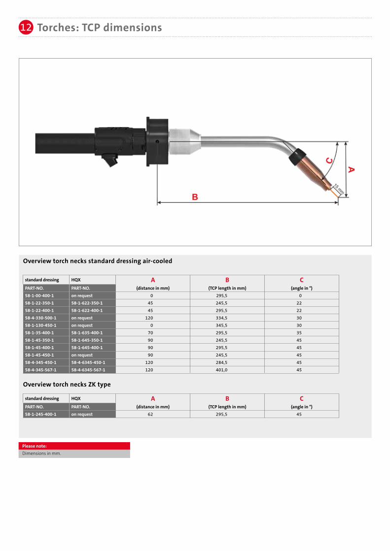
Torches: TCP dimensions12
Overview torch necks standard dressing air-cooled
Overview torch necks ZK type
Please note:Dimensions in mm.
standard dressing HQX A B C
PART-NO. PART-NO. (distance in mm) (TCP length in mm) (angle in °)58-1-245-400-1 on request 62 295,5 45
standard dressing HQX A B C
PART-NO. PART-NO. (distance in mm) (TCP length in mm) (angle in °)58-1-00-400-1 on request 0 295,5 058-1-22-350-1 58-1-622-350-1 45 245,5 2258-1-22-400-1 58-1-622-400-1 45 295,5 2258-4-330-500-1 on request 120 334,5 3058-1-130-450-1 on request 0 345,5 3058-1-35-400-1 58-1-635-400-1 70 295,5 3558-1-45-350-1 58-1-645-350-1 90 245,5 4558-1-45-400-1 58-1-645-400-1 90 295,5 4558-1-45-450-1 on request 90 245,5 4558-4-345-450-1 58-4-6345-450-1 120 284,5 4558-4-345-567-1 58-4-6345-567-1 120 401,0 45

Subject to change.
SKS Welding Systems GmbH | Marie-Curie-Strasse 14 | 67661 Kaiserslautern | [email protected] | www.sks-welding.com