mag-193 v5 efl-is technical datasheet - ampcontrol€¦ · mag-193 efl-is technical datasheet...
TRANSCRIPT

TECHNICAL
DATASHEET
EFL-IS Technical Datasheet MAG-193 Version 5 19 MAR 2020
Page 1 of 4 ampcontrolgroup.com
[email protected] +61 1300 267 373
AP
PR
OV
ED
FO
R E
XT
ER
NA
L D
IST
RIB
UT
ION
– P
RO
PE
RT
Y O
F A
MP
CO
NT
RO
L P
TY
LT
D
–
NO
T T
O B
E R
EP
RO
DU
CE
D IN
PA
RT
UpstreamCircuit Breaker
To Indication Circuit(Energised When Healthy)
To Indication Circuit(Energised When Healthy)
24Vdc or 24VacSupply
To CB UVCoil Supply
EFL-ISRelayMain
Contactor
A B C
A B C
Trailing/Reeling Cable
UV
EFL-ISBarrier
1 2 3 4
MCMain Contactor
Auxiliary Contact
14
13
10
9
CBR-NO
CBR-COM
15CBR-NC
MCR-NO
MCR-COM
MCR-NC
17
18
MCI-NO
MCI-COM
30
31VcmA
VcmB
1POWER1
2POWER2
5
6
7
8
25
26
NC
COM
EFLO TRIPINDICATION
TESTDELAY
NC
COM
RESET-NO
RESET-COM
EFLO & UV Trip ResetN/O Pushbutton
Load
RUN-NO
RUN-COM
21EARTH
VcmC32
VcmA
VcmB
VcmC
Ua
Ub
Uc
6
7
8
START MC-STOPEFL-MCR
INT
Typical Control Schematic:
INT
INT
MC
CB-STOPEFL-CBR
UV
RUN INPUTFC TRIP RESET PUSHBUTTON
11
Interposing Relay
19
INT 20
Interposing Coil Supply
Enclosure
MC Coil Supply
Co
ntacts En
ergised W
hen
Health
y
NOTE: TERMINALS 3, 4, 12, 16, 22, 23, 24 & 29 ARE NOT CONNECTED
Test Delay Input
27NO
28COM
EFL-IS – I.S. EFLO & FC PROTECTION RELAY IECEx TRA 15.0011X, Compliant with AS/NZS 2081:2011, Sections 7 & 9
Application
The Ampcontrol EFL-IS relay is IECEx Ex ia certified and is compliant to AS/NZS 2081:2011 sections 7 & 9. It has been designed for installation on mining outlets supplying hazardous area equipment that require earth fault lockout and frozen contact protection. The EFL-IS is capable of being installed on a wide range of system voltages from 110V up to 1.1kV. In addition to EFLO and FC protection, the EFL-IS also offers a selectable undervoltage protection function.
Features
AS/NZS 2081:2011* compliant
IECEx Ex ia I Ma certification (Um 132Vrms withdrawn)
Earth Fault Lock-out (EFLO) protection
Frozen Contact (FC) protection
Selectable Undervoltage (UV) protection
Selectable Back EMF Timer
Compatible with a wide range of system voltages
Description
While the outlet’s main contactor is open, the EFL-IS relay will use an intrinsically safe signal to continually monitor the resistance of the outlet’s phase conductors to earth. If this resistance falls below an acceptable level the EFL-IS relay will initiate an EFLO trip, preventing the outlet from being started.
The EFL-IS relay will also monitor the state of the outlet’s main contactor. If voltage appears on the line when the contactor is open, a Frozen Contact electrical trip will occur. This FC output relay is intended to be used to open the upstream circuit breaker. If the main contactor is either open when it should be closed or closed when it should be open a Frozen Contact logical trip will occur, initiating an upstream circuit breaker trip. A Back EMF timer is also provided to inhibit the frozen contact electrical trip function for a short period after the main contactor is open.
The EFL-IS relay also has an undervoltage protection function which, if activated, will open the main contactor if the outlet voltage falls below 50% of the selected system voltage.
Diagram
MAG-193 EFL-IS TECHNICAL DATASHEET Version: 5, Date: MAR 2020
Uncontrolled Copy - Refer to Ampcontrol Website for Latest Version Page 2 of 4
AP
PR
OV
ED
FO
R E
XT
ER
NA
L D
IST
RIB
UT
ION
– P
RO
PE
RT
Y O
F A
MP
CO
NT
RO
L P
TY
LT
D
–
NO
T T
O B
E R
EP
RO
DU
CE
D IN
PA
RT
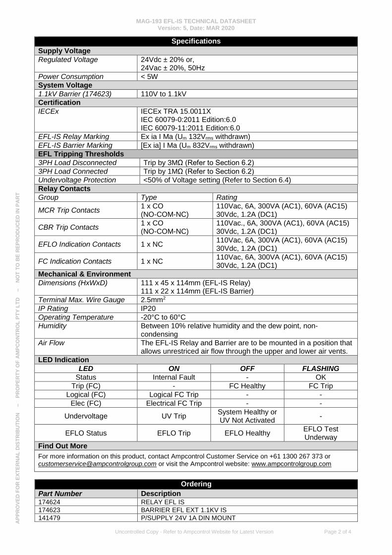
Specifications
Supply Voltage
Regulated Voltage 24Vdc ± 20% or, 24Vac ± 20%, 50Hz
Power Consumption < 5W
System Voltage
1.1kV Barrier (174623) 110V to 1.1kV
Certification
IECEx IECEx TRA 15.0011X IEC 60079-0:2011 Edition:6.0 IEC 60079-11:2011 Edition:6.0
EFL-IS Relay Marking Ex ia I Ma (Um 132Vrms withdrawn)
EFL-IS Barrier Marking [Ex ia] I Ma (Um 832Vrms withdrawn)
EFL Tripping Thresholds
3PH Load Disconnected Trip by 3MΩ (Refer to Section 6.2)
3PH Load Connected Trip by 1MΩ (Refer to Section 6.2)
Undervoltage Protection <50% of Voltage setting (Refer to Section 6.4)
Relay Contacts
Group Type Rating
MCR Trip Contacts 1 x CO (NO-COM-NC)
110Vac, 6A, 300VA (AC1), 60VA (AC15) 30Vdc, 1.2A (DC1)
CBR Trip Contacts 1 x CO (NO-COM-NC)
110Vac., 6A, 300VA (AC1), 60VA (AC15) 30Vdc, 1.2A (DC1)
EFLO Indication Contacts 1 x NC 110Vac, 6A, 300VA (AC1), 60VA (AC15) 30Vdc, 1.2A (DC1)
FC Indication Contacts 1 x NC 110Vac, 6A, 300VA (AC1), 60VA (AC15) 30Vdc, 1.2A (DC1)
Mechanical & Environment
Dimensions (HxWxD) 111 x 45 x 114mm (EFL-IS Relay) 111 x 22 x 114mm (EFL-IS Barrier)
Terminal Max. Wire Gauge 2.5mm2
IP Rating IP20
Operating Temperature -20°C to 60°C
Humidity Between 10% relative humidity and the dew point, non-condensing
Air Flow The EFL-IS Relay and Barrier are to be mounted in a position that allows unrestriced air flow through the upper and lower air vents.
LED Indication
LED ON OFF FLASHING
Status Internal Fault - OK
Trip (FC) - FC Healthy FC Trip
Logical (FC) Logical FC Trip - -
Elec (FC) Electrical FC Trip - -
Undervoltage UV Trip System Healthy or UV Not Activated
-
EFLO Status EFLO Trip EFLO Healthy EFLO Test Underway
Find Out More
For more information on this product, contact Ampcontrol Customer Service on +61 1300 267 373 or [email protected] or visit the Ampcontrol website: www.ampcontrolgroup.com
Ordering
Part Number Description 174624 RELAY EFL IS 174623 BARRIER EFL EXT 1.1KV IS 141479 P/SUPPLY 24V 1A DIN MOUNT

MAG-193 EFL-IS TECHNICAL DATASHEET Version: 5, Date: MAR 2020
Uncontrolled Copy - Refer to Ampcontrol Website for Latest Version Page 3 of 4
AP
PR
OV
ED
FO
R E
XT
ER
NA
L D
IST
RIB
UT
ION
– P
RO
PE
RT
Y O
F A
MP
CO
NT
RO
L P
TY
LT
D
–
NO
T T
O B
E R
EP
RO
DU
CE
D IN
PA
RT
Certification
Certification details
IECEx IECEx TRA 15.0011X
Applicant Ampcontrol CSM Pty Ltd
7 Billbrooke Close.
Cameron Park, NSW 2285
Australia
EFL-IS Relay Marking Ex ia I Ma (Um 132Vrms withdrawn)
EFL-IS Barrier Marking [Ex ia] I Ma (Um 832Vrms withdrawn)
Ambient Temperature -20˚C to + 60˚C
Standards
IEC 60079-0:2011 Edition:6.0
Explosive atmospheres – Part 0: General requirements
IEC 60079-11:2011 Edition:6.0
Explosive atmospheres – Part 11: Equipment protection by intrinsic safety “i”
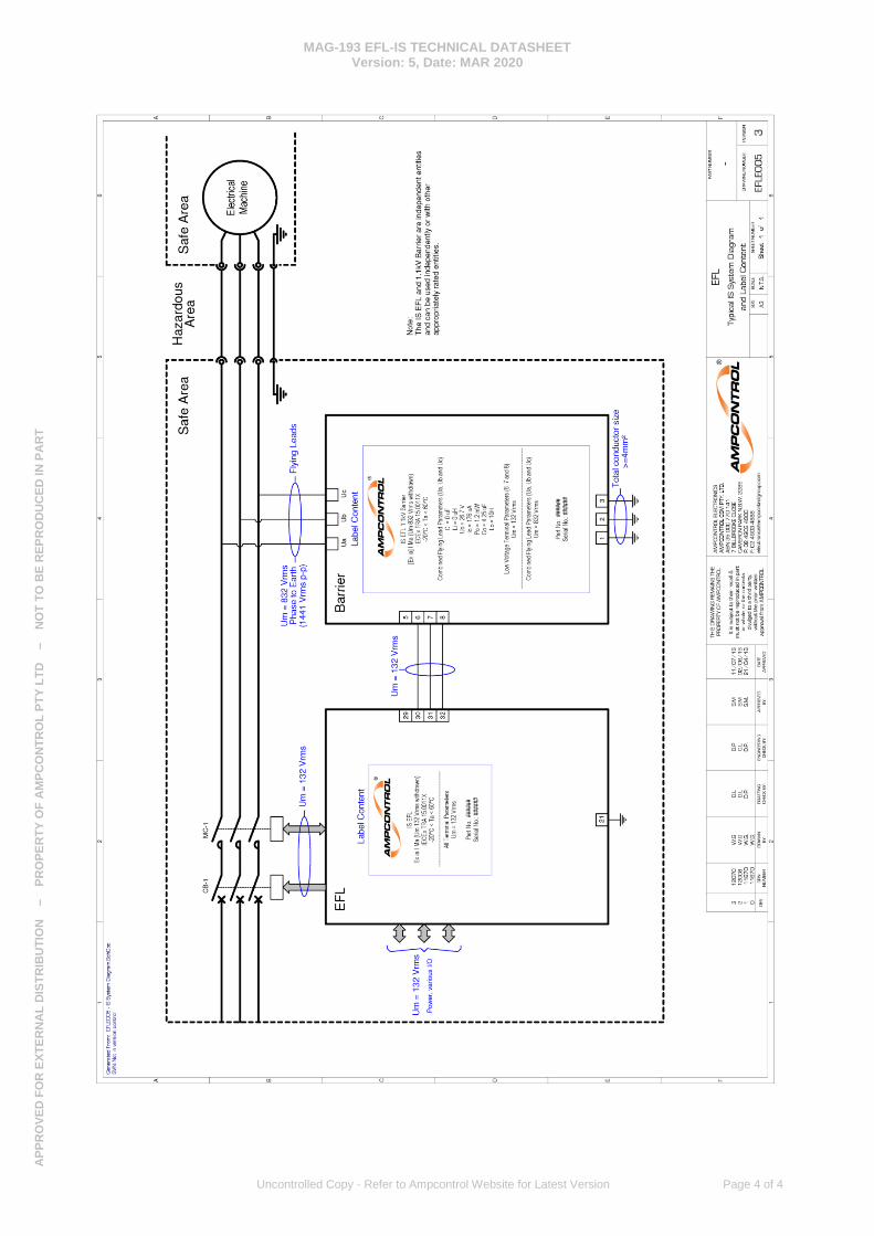
EFL Barrier
The barrier has a combination of low voltage (Um=132V) and high voltage, the fly leads have a combined Um=832V and Uo=26.7V.
EFL Relay
The apparatus is powered from AC mains and powered by a nominal 132VAC.
Conditions of Certification pertaining to Issue 0 of this Certificate
1. The EFL equipment is to be installed in a non-hazardous (safe) area. The ambient temperature range is -20˚C to + 60˚C.
2. The EFL is to be housed in a suitable enclosure that provides a degree of protection of not less than IP54.
3. The earth terminals of the EFL Barrier must be connected to a mains earth system via three (3) earth conductors making a combined 4mm². These provide ongoing electrical safety and maintain the intrinsic safety and certification.
4. The electrical parameters in the below table shall be taken into account during installation.
EFL Relay Entity Parameters
Function Terminals Um Uo Io Po Co Lo
110V Incoming
Power All Connections 132V - - - - -
EFL Barrier Entity Parameters
Function Terminals Um Uo Io Po Co Lo
High Voltage Leads
Ua, Ub, & Uc 832V 26.7V 176uA 1.2mW 4.25uF 10H
Low Voltage Terminals
5,6,7 132V - - - - -
Typical IS System Diagram
Drawing Number EFLE005 (See following page)
DISCLAIMER
While every effort has been made to ensure the accuracy of this document at the date of issue, Ampcontrol assumes no liability resulting from any omissions or errors in this document, and reserves the right to revise content at any time.
MAG-193 EFL-IS TECHNICAL DATASHEET Version: 5, Date: MAR 2020
Uncontrolled Copy - Refer to Ampcontrol Website for Latest Version Page 4 of 4
AP
PR
OV
ED
FO
R E
XT
ER
NA
L D
IST
RIB
UT
ION
– P
RO
PE
RT
Y O
F A
MP
CO
NT
RO
L P
TY
LT
D
–
NO
T T
O B
E R
EP
RO
DU
CE
D IN
PA
RT