magnesium borate fiber coating separators with high
TRANSCRIPT

1
2
3
4
5
6
7
8
9
10
11
12
13
14
15
16
17
18
19
20
21
22
23
24
25
26
27
28
29
30
31
32
33
34
35
36
37
38
39
40
41
42
43
44
45
46
47
48
49
50
51
52
53
54
55
56
57
Magnesium Borate Fiber Coating Separators with HighLithium-Ion Transference Number for Lithium-Ion BatteriesXin Wang,[a] Longqing Peng,[a] Haiming Hua,[a] Yizheng Liu,[b] Peng Zhang,*[b] andJinbao Zhao*[a, b]
In this work, magnesium borate fiber (MBO) is used as afunctional ceramic to coat onto a polypropylene (PP) separator(MBO@PP). This MBO coating layer increases the lithium-iontransference number (tLi+) from 0.24 to 0.57 in the LiPF6-basedelectrolyte due to the MBO acting as Lewis acid sites interactswith Lewis base PF�6 . The increase in the tLi+ reduces the
concentration polarization and promotes the migration oflithium ions. Besides, the prepared MBO@PP separator hasbetter wettability with liquid electrolyte, the electrolyte uptakeas well as thermal stability. The LiFePO4 half-coin with MBO@PPseparator not only had better cycle stability, but also had ahigher capacity retention rate at high current.
1. Introduction
Lithium-ion batteries (LIBs) are widely used as energy storagedevices in our daily lives due to their high energy density, longcycle life, and low cost. Many researches and developmentshave been done to further improve their electrochemicalperformance such as energy density, high current charge anddischarge rate as while as safety for application in large scaleenergy storage and electric vehicles power sources.[1–3] As anindispensable component of LIBs, separators should also havetheir contributions in these respects. Since the conventionalporous polyolefin separator severely shrinks at elevated temper-ature and could cause short circuit of the electrodes whichwould lead to the thermal runaway and explosion of thebattery, thus lots of work has been done in recent years toimprove the thermal stability of the commercial polyolefinseparator. For example, our group coated nano-ceramicpowders such as Al2O3 onto commercial polyolefin separator toimprove thermal stability by enlarging the temperature rangebetween shutdown and melting down as well as the dimen-sional stability at increased temperature.[4,5] Zhu et al. depositeda thin layer of TiO2 onto polypropylene (PP) separator byAtomic Layer Deposition (ALD) technology to overcome thethermal shrinkage and poor wettability of PP separator.[6,7] Leeet al. studied the effect of SiO2 coating with different particlesizes on polyolefin separator.[8,9] However, most of the devel-
oped ceramic coated separators (CCS) are prepared by modify-ing commercial polyolefin separator with electrochemical inertsolids (Al2O3/TiO2/SiO2), mainly aiming to improve the physicalproperties as thermal stability of the separator. However, theyare not effective enough in the current state of the art inpursuit of better electrochemical performance as higher energydensity, higher power density and so on. Therefore, besidesensuring the safety of the separator, it is an attractive way toendow the separator with certain electrochemical functions bysimply introducing some functional ceramic materials.
Lithium ion transference number (tLi+), representing theratio of conductivity contribution of lithium ion is an importantparameter of LIBs due to only Li+ ions participate in theelectrochemical reaction, namely Li+ ions insertion/extrusionprocess. Unfortunately, the tLi+ of most lithium salt in carbonatebased electrolyte with polyolefin separator is generally lowerthan 0.5, only about 0.2–0.4,[10–12] meaning that the mostmigration ions in the electrolyte is anionic ions as PF�6 , which iseasily to cause concentration polarization, voltage drop,[10,13]
undesirable reaction and lithium dendrite generation and finallylead to the deterioration of cell performance.[14] Therefore, it isnecessary to increase tLi+ to further improve the electro-chemical performance of advanced LIBs. The most representa-tive strategy is the single-ion polymer electrolyte, which directlyimmobilizes the anionic group on the polymer backbones thusgain a complete Li ions conductance with tLi+ of close to 1.[15–17]
However, the low ionic conductivity (lower than 10� 5 S · cm� 1 atroom temperature) of such polymer electrolytes greatly hindersits application. So, to balance the requirements of conductivityand lithium ion migration, a simple method based on Lewisacid-base interaction is also developed to increase tLi+.[18] Forexample, Wang et al. deposited ZrO2 with Lewis acid sites ontothe separator to absorb Lewis base species in the electrolyte,PF�6 and increase tLi+ by electrostatic interaction.[12,19] The ZSM-5molecular sieve with amounts of Lewis acid sites based on Si� Oand Al� O backbones was also used as the coating layer on theseparator to absorb PF�6 thus the tLi+ increases from 0.28 to0.44.[11] In addition, it has been reported that electron-deficientfunctional group such as boron atoms in the borate ester
[a] X. Wang, L. Peng, H. Hua, Prof. J. ZhaoState Key Lab of Physical Chemistry of Solid SurfacesCollaborative Innovation Centre of Chemistry for Energy MaterialsEngineering Research Center of Electrochemical TechnologyMinistry of Education, State-Province Joint Engineering Laboratory of PowerSourceTechnology for New Energy VehicleCollege of Chemistry and Chemical EngineeringXiamen University, Xiamen 361005, P.R.ChinaE-mail: [email protected]
[b] Y. Liu, Dr. P. Zhang, Prof. J. ZhaoCollege of Energy, Xiamen UniversityXiamen 361005, P.R. ChinaE-mail: [email protected] information for this article is available on the WWW underhttps://doi.org/10.1002/celc.201901916
ArticlesDOI: 10.1002/celc.201901916
1187ChemElectroChem 2020, 7, 1187–1192 © 2020 Wiley-VCH Verlag GmbH & Co. KGaA, Weinheim
Wiley VCH Montag, 09.03.2020
2005 / 159834 [S. 1187/1192] 1
1
2
3
4
5
6
7
8
9
10
11
12
13
14
15
16
17
18
19
20
21
22
23
24
25
26
27
28
29
30
31
32
33
34
35
36
37
38
39
40
41
42
43
44
45
46
47
48
49
50
51
52
53
54
55
56
57
polymers can also adsorb anions to increase the tLi+.[20–22]
Inspired by the above works combined with our previous work,we envisage the application of borate inorganic ceramics withboth B� O electron-deficient group and high thermal shrinkageresistance of ceramic materials on the polyolefin separator. Onone hand, borate-based ceramics can improve the thermalstability of the polyolefin separator same as the mechanism ofAl2O3/SiO2 ceramics coating layer to ensure its dimensionalstability at elevated temperature. On the other hand, it alsocontains electron-deficient boron-oxygen function groups,which can capture anions through Lewis acid-base interactionto hinder the conductance of anions and increase tLi+ in thecell. Here, we have chosen the common magnesium boratematerial, and in order to further enhance the interactionsbetween borate-based ceramics and the anions, we selectedmagnesium borate Mg2B2O5 fiber with one-dimensional struc-ture and constructed a staggered three-dimensional grid ontothe surface of separator to further enlarge the contact area andinteraction sites of magnesium borate and the liquid electrolyte.Our results show this simple strategy could improve theperformance of both thermal stability and electrochemicalperformance of the lithium ion battery for practical application.
2. Results and Discussion
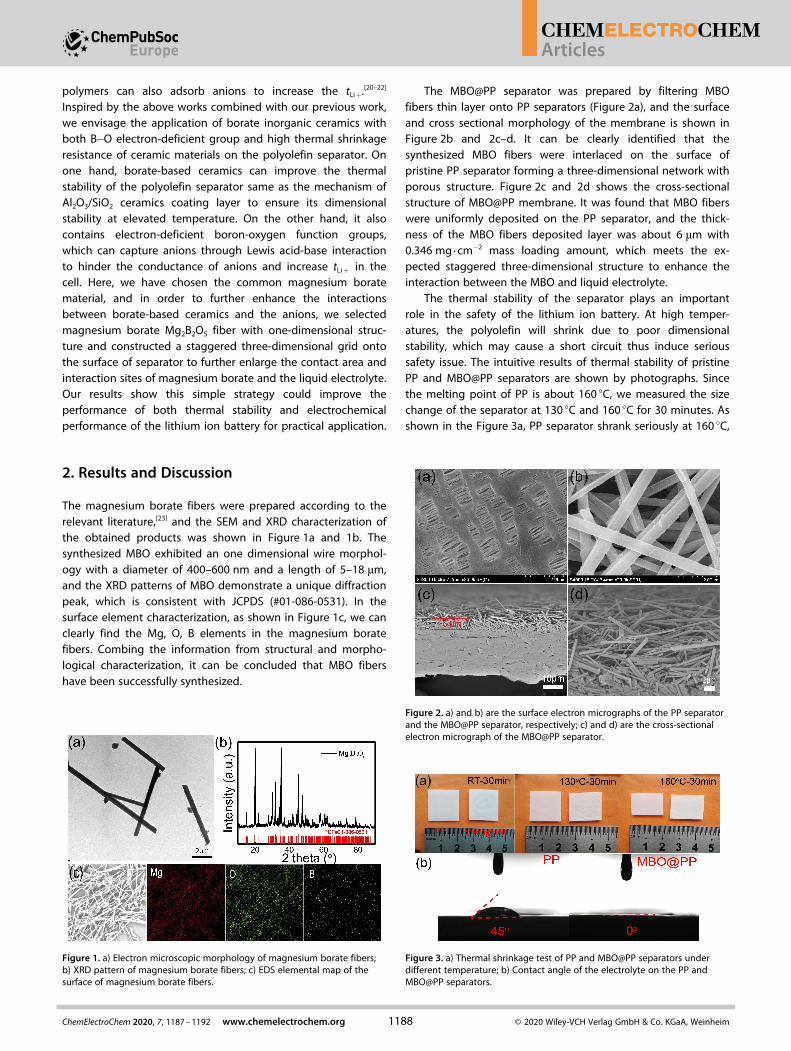
The magnesium borate fibers were prepared according to therelevant literature,[23] and the SEM and XRD characterization ofthe obtained products was shown in Figure 1a and 1b. Thesynthesized MBO exhibited an one dimensional wire morphol-ogy with a diameter of 400–600 nm and a length of 5–18 μm,and the XRD patterns of MBO demonstrate a unique diffractionpeak, which is consistent with JCPDS (#01-086-0531). In thesurface element characterization, as shown in Figure 1c, we canclearly find the Mg, O, B elements in the magnesium boratefibers. Combing the information from structural and morpho-logical characterization, it can be concluded that MBO fibershave been successfully synthesized.
The MBO@PP separator was prepared by filtering MBOfibers thin layer onto PP separators (Figure 2a), and the surfaceand cross sectional morphology of the membrane is shown inFigure 2b and 2c–d. It can be clearly identified that thesynthesized MBO fibers were interlaced on the surface ofpristine PP separator forming a three-dimensional network withporous structure. Figure 2c and 2d shows the cross-sectionalstructure of MBO@PP membrane. It was found that MBO fiberswere uniformly deposited on the PP separator, and the thick-ness of the MBO fibers deposited layer was about 6 μm with0.346 mg ·cm� 2 mass loading amount, which meets the ex-pected staggered three-dimensional structure to enhance theinteraction between the MBO and liquid electrolyte.
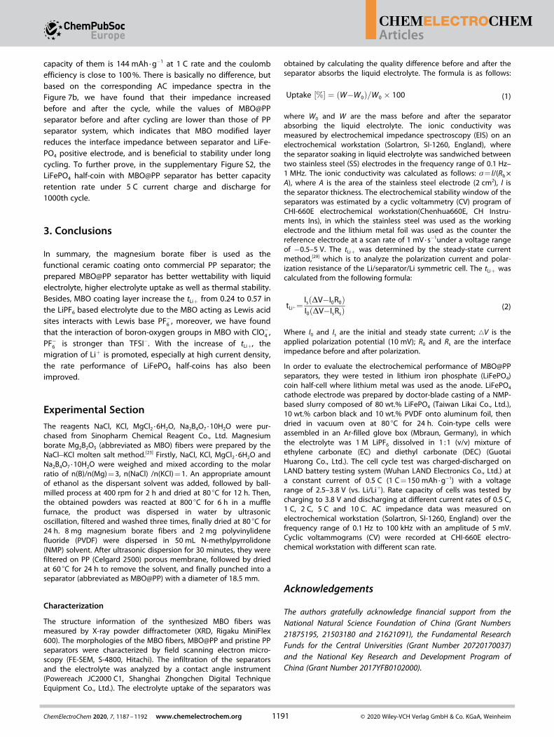
The thermal stability of the separator plays an importantrole in the safety of the lithium ion battery. At high temper-atures, the polyolefin will shrink due to poor dimensionalstability, which may cause a short circuit thus induce serioussafety issue. The intuitive results of thermal stability of pristinePP and MBO@PP separators are shown by photographs. Sincethe melting point of PP is about 160 °C, we measured the sizechange of the separator at 130 °C and 160 °C for 30 minutes. Asshown in the Figure 3a, PP separator shrank seriously at 160 °C,
Figure 1. a) Electron microscopic morphology of magnesium borate fibers;b) XRD pattern of magnesium borate fibers; c) EDS elemental map of thesurface of magnesium borate fibers.
Figure 2. a) and b) are the surface electron micrographs of the PP separatorand the MBO@PP separator, respectively; c) and d) are the cross-sectionalelectron micrograph of the MBO@PP separator.
Figure 3. a) Thermal shrinkage test of PP and MBO@PP separators underdifferent temperature; b) Contact angle of the electrolyte on the PP andMBO@PP separators.
Articles
1188ChemElectroChem 2020, 7, 1187–1192 www.chemelectrochem.org © 2020 Wiley-VCH Verlag GmbH & Co. KGaA, Weinheim
Wiley VCH Montag, 09.03.2020
2005 / 159834 [S. 1188/1192] 1

1
2
3
4
5
6
7
8
9
10
11
12
13
14
15
16
17
18
19
20
21
22
23
24
25
26
27
28
29
30
31
32
33
34
35
36
37
38
39
40
41
42
43
44
45
46
47
48
49
50
51
52
53
54
55
56
57
however, due to the presence of the MBO ceramic layer withhigh thermal resistance, the MBO@PP separator have inhibitedthe shrinkage to a certain extent and thermal stability of theseparator was improved. As presented in Figure 3b, the contactangle of MBO@PP separator with EC/DEC electrolyte is reducedfrom 45° to 0° compared with that of PP separator. The MBOcoating layer with three-dimensional network structure hasbetter wettability with liquid electrolyte, which is beneficial tofaster ion transportation and lower interface impedancebetween electrolyte and electrode. By calculating the masschange of the separator immersing in the electrolyte, theelectrolyte uptake of PP and MBO@PP separators are 115% and160%, respectively. Firstly, the one dimension fiber formedthree-dimensional network with high porosity facilitates theinfiltration of the liquid electrolyte and increases the electrolyteuptake. Secondly, this network structure composed of inter-laced MBO fibers could also effectively enlarge the contact areabetween MBO and anions in the liquid electrolyte.
Due to the enhancement of hydrophilicity of the ceramicmaterials and three-dimensional network structure formed bythe MBO fibers, the electrolyte uptake of MBO@PP separator issignificantly higher than that of PP separator. The ionicconductivity of MBO@PP separator calculated by the ACimpedance (Figure 4a) is 0.98 mS ·cm� 1 at 30 °C, which is slightlyhigher than that of 0.96 mS · cm� 1 of the PP separator. Theelectrochemical stability of the MBO@PP separator was charac-terized by testing the cyclic voltammogram of the Li/separator/SS cells.[24,25] As shown in the Figure 4b, there is no other peakexcept for the deposition and peeling peak of lithium between1 to 5 V versus Li/Li+. It is indicated that the addition of MBOdid not introduce other electrochemical side reactions and didnot affect the electrochemical stability of the PP separator. Inaddition, it should be noticed that the over potential of lithiummetal deposition and stripping on stainless steel decreases afterthe PP separator was coated with MBO, which could be ascribed
to the polarization was reduced. The properties of MBO@PPseparator was summarized in Table 1.
Magnesium borate coating layer has not only improved thethermal stability of PP separator, but also increased the tLi+ ofthe electrolyte. As shown in Figure 4c and 4d, the tLi+ ofMBO@PP have increased from 0.24 to 0.57 compared with thatof PP separator. It can be concluded that the boron-oxygenunits in MBO acting as Lewis acid sites interacts with Lewis basePF�6 , which restricts the migration of PF�6 and in turn promotesthe migration of Li+, so the tLi+ of MBO@PP increased.[20,21,26]
Furthermore, the one dimensional fiber structure we introducedto form the coating layer enlarges the contact sites with theanions in the liquid and also could construct an one dimen-sional Li+ conduction pathway. The increase of migrationnumber is beneficial to reduce concentration polarization,especially in the case of high current density, and improve cellperformance.[10]
To further investigate the interaction of MBO with differentlithium salt anions, we also have tested the tLi+ of MBO@PP indifferent lithium salt electrolyte, i. e. 1 M LiClO4 dissolved in EC/DEC (v/v=1), 1 M LiTFSI dissolved in EC/DEC (v/v=1). As shownin Figure 5, in LiClO4 system, compared with PP separator, thetLi+ of MBO@PP increased from 0.15 to 0.58, which indicatedthat the MBO can also capture ClO�4 .[27] However, in the LiTFSIsystem, it is regret that the MBO@PP separator has notimproved the tLi+, and it is likely that MBO has a weakerinteraction with the TFSI� anion. From the above changes inthe value of tLi+ in the electrolyte of different lithium salts, wecan find that the interaction of boron-oxygen groups in MBO
Figure 4. a) Ionic conductivity of PP and MBO@PP separators; b) cyclicvoltammetry curves of PP and MBO@PP separators with stainless steel as theworking electrode, lithium as reference and counter electrodes at a scan rateof 1 mV · s-1; Chronoamperometry curves of PP (c) and MBO@PP (d)separators soaked by electrolyte in Li-symmetric cells, insert: AC impedancecurves of the cells before and after polarization.
Table 1. Basic properties of PP and MBO@PP separator.
Separator Thickness[μm]
Electrolyteuptake [%]
Contactangle [°]
Ionicconductivity[mS/cm]
tLi+
PP 25 115 45° 0.96 0.24MBO@PP 31 160 0° 0.98 0.57
Figure 5. a) and b) Chronoamperometry profiles of PP and MBO@PPseparators soaked by LiClO4 electrolyte in Li-symmetric cells; c) and d)Chronoamperometry profiles of PP and MBO@PP separators soaked by LiTFSIelectrolyte in Li-symmetric cells.
Articles
1189ChemElectroChem 2020, 7, 1187–1192 www.chemelectrochem.org © 2020 Wiley-VCH Verlag GmbH & Co. KGaA, Weinheim
Wiley VCH Montag, 09.03.2020
2005 / 159834 [S. 1189/1192] 1

1
2
3
4
5
6
7
8
9
10
11
12
13
14
15
16
17
18
19
20
21
22
23
24
25
26
27
28
29
30
31
32
33
34
35
36
37
38
39
40
41
42
43
44
45
46
47
48
49
50
51
52
53
54
55
56
57
with ClO�4 , PF�6 is stronger than TFSI� , the relevant reason maybe that the Lewis basicity of TFSI� is weaker than that of theformer two. According to the soft and hard acid-base principle,the boron-oxygen group as a hard Lewis acid site interacts withhard anions of ClO�4 or PF�6 to be stronger than the soft anionTFSI� .[27,28]
In order to fully understand the effect of MBO modifiedlayer on the electrochemical performance of electrodes, weassembled MBO@PP separator in the stable commercial cath-ode material LiFePO4 half-coin and tested the rate performance.According to the results of the rate performance test of theLiFePO4 half-coins (Figure 6a), with the increases of thedischarge current density, the discharge capacity of LiFePO4
cells assembled with MBO@PP and PP separators is decreased,specifically, when the charge-discharge rate is less than 2 C,there is no difference in the discharge capacity of MBO@PP andPP separators, 150 mAh ·g� 1 (0.5 C), 144 mAh ·g� 1 (1 C) and133 mAh ·g� 1 (2 C). When the rate continues to increase to 5 C,the discharge capacity of the LiFePO4 cells equipped withMBO@PP and PP separators shows apparent difference, espe-cially when the rate is 10 C, the discharge capacity of MBO@PPseparator is maintained at 95 mAh ·g� 1 (10 C), which is greaterthan 72 mAh ·g� 1 (10 C) of the PP separator. This is becauseMBO@PP separator has higher Li+ ionic conductivity than thatof PP separator, which calculated from the apparent ionicconductivity multiplied by tLi+. It should be pointed out thatalthough the apparent ionic conductivity from EIS test of PP
and MBO@PP is almost the same, but the obtained higher tLi+
of MBO@PP increases the conduction of Li+ to promote theelectrochemical reaction of LIBs, companied by reducingconcentration polarization, and easier transmission of lithiumions at high current density, so it has higher dischargecapacity.[12,13] Similar situation can also be found in the relevantcapacity-voltage curves (Figure 6b and 6c), before the current isless than 2 C, the related discharge platforms of MBO@PP andPP separators are not different, so there is no difference indischarge capacity; when the current density continues toincrease to 5 C or 10 C, the discharge platform of LiFePO4 half-cell with PP separators is reduced to 2.87 V (5 C), 2.67 V (10 C),while LiFePO4 half-cell with MBO@PP separator can maintainthe discharge platform to 3.22 V (5 C), 3.05 V (10 C). We canconclude that the LiFePO4 half-cell equipped with MBO@PPseparator has a smaller polarization, especially at high currentdensity, so it has a higher discharge platform and a higherdischarge capacity. A more detailed characterization wasachieved by cyclic voltammetry at different scanning rate, asshown in the supplementary Figure S1, when scanning rateincreases, the potential difference becomes more obvious, butMBO@PP separator has smaller peak gap than PP separator atthe same scanning rate, and the faster the scanning rate, thelarger the difference is, indicating that the addition of MBOmodified layer enhances the reversibility of LiFePO4, promotesbetter cycle stability, and MBO@PP separator has a clearadvantage at faster scanning rate. This result is consistent withthe capacity-voltage curves, repeating that the MBO modifica-tion layer reduces the concentration polarization and the loss ofdischarge capacity of LiFePO4 at high current density.
The cycle performance of LiFePO4 half-coins assembled withPP and MBO@PP separators is shown in Figure 7a, the discharge
Figure 6. a) Discharge C-rate capabilities of LiFePO4 half-coins assembledwith PP and MBO@PP separators; b) and c) are related discharge profiles ofcells.
Figure 7. a) Cycle performance and columbic efficiency of LiFePO4/Li half-coins at 1 C rate assembled with PP and MBO@PP separator; b) correspond-ing AC impedance spectra of LiFePO4 half-coins at 2th and 100th cycles.
Articles
1190ChemElectroChem 2020, 7, 1187–1192 www.chemelectrochem.org © 2020 Wiley-VCH Verlag GmbH & Co. KGaA, Weinheim
Wiley VCH Montag, 09.03.2020
2005 / 159834 [S. 1190/1192] 1
1
2
3
4
5
6
7
8
9
10
11
12
13
14
15
16
17
18
19
20
21
22
23
24
25
26
27
28
29
30
31
32
33
34
35
36
37
38
39
40
41
42
43
44
45
46
47
48
49
50
51
52
53
54
55
56
57
capacity of them is 144 mAh ·g� 1 at 1 C rate and the coulombefficiency is close to 100%. There is basically no difference, butbased on the corresponding AC impedance spectra in theFigure 7b, we have found that their impedance increasedbefore and after the cycle, while the values of MBO@PPseparator before and after cycling are lower than those of PPseparator system, which indicates that MBO modified layerreduces the interface impedance between separator and LiFe-PO4 positive electrode, and is beneficial to stability under longcycling. To further prove, in the supplementary Figure S2, theLiFePO4 half-coin with MBO@PP separator has better capacityretention rate under 5 C current charge and discharge for1000th cycle.
3. Conclusions
In summary, the magnesium borate fiber is used as thefunctional ceramic coating onto commercial PP separator; theprepared MBO@PP separator has better wettability with liquidelectrolyte, higher electrolyte uptake as well as thermal stability.Besides, MBO coating layer increase the tLi+ from 0.24 to 0.57 inthe LiPF6 based electrolyte due to the MBO acting as Lewis acidsites interacts with Lewis base PF�6 , moreover, we have foundthat the interaction of boron-oxygen groups in MBO with ClO�4 ,PF�6 is stronger than TFSI� . With the increase of tLi+, themigration of Li+ is promoted, especially at high current density,the rate performance of LiFePO4 half-coins has also beenimproved.
Experimental SectionThe reagents NaCl, KCl, MgCl2 · 6H2O, Na2B4O7 · 10H2O were pur-chased from Sinopharm Chemical Reagent Co., Ltd. Magnesiumborate Mg2B2O5 (abbreviated as MBO) fibers were prepared by theNaCl� KCl molten salt method.[23] Firstly, NaCl, KCl, MgCl2 · 6H2O andNa2B4O7 ·10H2O were weighed and mixed according to the molarratio of n(B)/n(Mg)=3, n(NaCl) /n(KCl)=1. An appropriate amountof ethanol as the dispersant solvent was added, followed by ball-milled process at 400 rpm for 2 h and dried at 80 °C for 12 h. Then,the obtained powders was reacted at 800 °C for 6 h in a mufflefurnace, the product was dispersed in water by ultrasonicoscillation, filtered and washed three times, finally dried at 80 °C for24 h. 8 mg magnesium borate fibers and 2 mg polyvinylidenefluoride (PVDF) were dispersed in 50 mL N-methylpyrrolidone(NMP) solvent. After ultrasonic dispersion for 30 minutes, they werefiltered on PP (Celgard 2500) porous membrane, followed by driedat 60 °C for 24 h to remove the solvent, and finally punched into aseparator (abbreviated as MBO@PP) with a diameter of 18.5 mm.
Characterization
The structure information of the synthesized MBO fibers wasmeasured by X-ray powder diffractometer (XRD, Rigaku MiniFlex600). The morphologies of the MBO fibers, MBO@PP and pristine PPseparators were characterized by field scanning electron micro-scopy (FE-SEM, S-4800, Hitachi). The infiltration of the separatorsand the electrolyte was analyzed by a contact angle instrument(Powereach JC2000 C1, Shanghai Zhongchen Digital TechniqueEquipment Co., Ltd.). The electrolyte uptake of the separators was
obtained by calculating the quality difference before and after theseparator absorbs the liquid electrolyte. The formula is as follows:
Uptake ½%� ¼ ðW� W0Þ=W0 � 100 (1)
where W0 and W are the mass before and after the separatorabsorbing the liquid electrolyte. The ionic conductivity wasmeasured by electrochemical impedance spectroscopy (EIS) on anelectrochemical workstation (Solartron, SI-1260, England), wherethe separator soaking in liquid electrolyte was sandwiched betweentwo stainless steel (SS) electrodes in the frequency range of 0.1 Hz–1 MHz. The ionic conductivity was calculated as follows: σ= l/(Rb ×A), where A is the area of the stainless steel electrode (2 cm2), l isthe separator thickness. The electrochemical stability window of theseparators was estimated by a cyclic voltammetry (CV) program ofCHI-660E electrochemical workstation(Chenhua660E, CH Instru-ments Ins), in which the stainless steel was used as the workingelectrode and the lithium metal foil was used as the counter thereference electrode at a scan rate of 1 mV · s� 1under a voltage rangeof � 0.5–5 V. The tLi+ was determined by the steady-state currentmethod,[29] which is to analyze the polarization current and polar-ization resistance of the Li/separator/Li symmetric cell. The tLi+ wascalculated from the following formula:
tLiþ¼IsðDV� I0R0Þ
I0ðDV� IsRsÞ(2)
Where I0 and Is are the initial and steady state current; ~V is theapplied polarization potential (10 mV); R0 and Rs are the interfaceimpedance before and after polarization.
In order to evaluate the electrochemical performance of MBO@PPseparators, they were tested in lithium iron phosphate (LiFePO4)coin half-cell where lithium metal was used as the anode. LiFePO4
cathode electrode was prepared by doctor-blade casting of a NMP-based slurry composed of 80 wt.% LiFePO4 (Taiwan Likai Co., Ltd.),10 wt.% carbon black and 10 wt.% PVDF onto aluminum foil, thendried in vacuum oven at 80 °C for 24 h. Coin-type cells wereassembled in an Ar-filled glove box (Mbraun, Germany), in whichthe electrolyte was 1 M LiPF6 dissolved in 1 :1 (v/v) mixture ofethylene carbonate (EC) and diethyl carbonate (DEC) (GuotaiHuarong Co., Ltd.). The cell cycle test was charged-discharged onLAND battery testing system (Wuhan LAND Electronics Co., Ltd.) ata constant current of 0.5 C (1 C=150 mAh ·g� 1) with a voltagerange of 2.5–3.8 V (vs. Li/Li+). Rate capacity of cells was tested bycharging to 3.8 V and discharging at different current rates of 0.5 C,1 C, 2 C, 5 C and 10 C. AC impedance data was measured onelectrochemical workstation (Solartron, SI-1260, England) over thefrequency range of 0.1 Hz to 100 kHz with an amplitude of 5 mV.Cyclic voltammograms (CV) were recorded at CHI-660E electro-chemical workstation with different scan rate.
Acknowledgements
The authors gratefully acknowledge financial support from theNational Natural Science Foundation of China (Grant Numbers21875195, 21503180 and 21621091), the Fundamental ResearchFunds for the Central Universities (Grant Number 20720170037)and the National Key Research and Development Program ofChina (Grant Number 2017YFB0102000).
Articles
1191ChemElectroChem 2020, 7, 1187–1192 www.chemelectrochem.org © 2020 Wiley-VCH Verlag GmbH & Co. KGaA, Weinheim
Wiley VCH Montag, 09.03.2020
2005 / 159834 [S. 1191/1192] 1

1
2
3
4
5
6
7
8
9
10
11
12
13
14
15
16
17
18
19
20
21
22
23
24
25
26
27
28
29
30
31
32
33
34
35
36
37
38
39
40
41
42
43
44
45
46
47
48
49
50
51
52
53
54
55
56
57
Keywords: Lithium ion battery · Mg2B2O5 fibers · Lithium iontransference number
[1] C. Liu, Z. G. Neale, G. Cao, Mater. Today 2016, 19, 109–123.[2] W. Zhang, Z. Tu, J. Qian, S. Choudhury, L. A. Archer, Y. Lu, Small 2017.[3] J. C. Bachman, S. Muy, A. Grimaud, H. H. Chang, N. Pour, S. F. Lux, O.
Paschos, F. Maglia, S. Lupart, P. Lamp, L. Giordano, Y. Shao-Horn, Chem.Rev. 2016, 116, 140–162.
[4] C. Shi, P. Zhang, L. X. Chen, P. T. Yang, J. B. Zhao, J. Power Sources 2014,270, 547–553.
[5] H.-S. Jeong, S. C. Hong, S.-Y. Lee, J. Membr. Sci. 2010, 364, 177–182.[6] H. Chen, Q. Lin, Q. Xu, Y. Yang, Z. P. Shao, Y. Wang, J. Membr. Sci. 2014,
458, 217–224.[7] X. Shen, C. Li, C. Shi, C. C. Yang, L. Deng, W. Zhang, L. Q. Peng, J. H. Dai,
D. Z. Wu, P. Zhang, J. B. Zhao, Appl. Surf. Sci. 2018, 441, 165–173.[8] H. S. Jeong, S. Y. Lee, J. Power Sources 2011, 196, 6716–6722.[9] J.-H. Park, J.-H. Cho, W. Park, D. Ryoo, S.-J. Yoon, J. H. Kim, Y. U. Jeong,
S.-Y. Lee, J. Power Sources 2010, 195, 8306–8310.[10] K. M. Diederichsen, E. J. McShane, B. D. McCloskey, ACS Energy Lett.
2017, 2, 2563–2575.[11] X. F. Mao, L. Y. Shi, H. J. Zhang, Z. Y. Wang, J. F. Zhu, Z. F. Qiu, Y. Zhao,
M. H. Zhang, S. Yuan, J. Power Sources 2017, 342, 816–824.[12] W. X. Xu, Z. Y. Wang, L. Y. Shi, Y. Ma, S. Yuan, L. N. Sun, Y. Zhao, M. H.
Zhang, J. F. Zhu, ACS Appl. Mater. Interfaces 2015, 7, 20678–20686.[13] R. Zahn, M. F. Lagadec, M. Hess, V. Wood, ACS Appl. Mater. Interfaces
2016, 8, 32637–32642.[14] A. Kushima, K. P. So, C. Su, P. Bai, N. Kuriyama, T. Maebashi, Y. Fujiwara,
M. Z. Bazant, J. Li, Nano Energy 2017, 32, 271–279.[15] H. Zhang, C. Li, M. Piszcz, E. Coya, T. Rojo, L. M. Rodriguez-Martinez, M.
Armand, Z. Zhou, Chem. Soc. Rev. 2017, 46, 797–815.
[16] E. Strauss, S. Menkin, D. Golodnitsky, J. Solid State Electrochem. 2017, 21,1879–1905.
[17] X. Shen, L. Peng, R. Li, H. Li, X. Wang, B. Huang, D. Wu, P. Zhang, J. Zhao,ChemElectroChem.
[18] F. Croce, L. Persi, B. Scrosati, F. Serraino-Fiory, E. Plichta, M. A.Hendrickson, Electrochim. Acta 2001, 46, 2457–2461.
[19] Z. Y. Wang, F. L. Guo, C. Chen, L. Y. Shi, S. Yuan, L. N. Sun, J. F. Zhu, ACSAppl. Mater. Interfaces 2015, 7, 3314–3322.
[20] B. S. Lalia, N. Yoshimoto, M. Egashira, M. Morita, J. Power Sources 2009,194, 531–535.
[21] J. Shim, J. S. Lee, J. H. Lee, H. J. Kim, J. C. Lee, ACS Appl. Mater. Interfaces2016, 8, 27740–27752.
[22] K. L. Mathews, A. M. Budgin, S. Beeram, A. T. Joenathan, B. D. Stein, U.Werner-Zwanziger, M. Pink, L. A. Baker, W. E. Mahmoud, J. P. Carini, L. M.Bronstein, J. Mater. Chem. A 2013, 1, 1108–1116.
[23] Y. Duan, G. M. Lu, X. F. Song, S. Y. Sun, J. G. Yu, J. Inorg. Mater. 2011, 26,364–368.
[24] L. Pan, H. B. Wang, C. L. M. Wu, C. B. Liao, L. Li, ACS Appl. Mater. Interfaces2015, 7, 16003–16010.
[25] W. Xu, X. Chen, F. Ding, J. Xiao, D. Wang, A. Pan, J. Zheng, X. S. Li, A. B.Padmaperuma, J.-G. Zhang, J. Power Sources 2012, 213, 304–316.
[26] M. Marcinek, A. Bac, P. Lipka, A. Zalewska, G. Zukowska, R. Borkowska,W. Wieczorek, J. Phys. Chem. B 2000, 104, 11088–11093.
[27] Y. Kato, K. Suwa, H. Ikuta, Y. Uchimoto, M. Wakihara, S. Yokoyama, T.Yabe, M. Yamamoto, J. Mater. Chem. 2003, 13, 280–285.
[28] M. Saito, H. Ikuta, Y. Uchimoto, M. Wakihara, S. Yokoyama, T. Yabe, M.Yamamoto, J. Phys. Chem. B 2003, 107, 11608–11614.
[29] J. Evans, C. A. Vincent, P. G. Bruce, Polymer 1987, 28, 2324–2328.
Manuscript received: November 14, 2019Revised manuscript received: January 6, 2020Accepted manuscript online: February 9, 2020
Articles
1192ChemElectroChem 2020, 7, 1187–1192 www.chemelectrochem.org © 2020 Wiley-VCH Verlag GmbH & Co. KGaA, Weinheim
Wiley VCH Montag, 09.03.2020
2005 / 159834 [S. 1192/1192] 1