magnetic contactors, magnetic starters return to main index · hand (supplied from factory) or...
TRANSCRIPT
3
Mag
netic
Con
tact
ors
Mag
netic
Sta
rter
s
Contactors
Overview
DIL...M ContactorsAC OperatedAC Operated, ReversingDC OperatedAC/DC Operated, DC Hp ratings
DIL Universal ContactorsAC/DC Operated
Contactors Selection & Ordering Guide
Non-Combination StartersAC Operated, FVNR StartersAC Operated, FVR StartersAC Operated, Two-Speed Starters
PKZ 2 Self-Protected Combination StartersFVNROpen type FVNR and FVR
Combination StartersBreaker Type, FVNR and FVRFusible Type, FVNR , Class JFusible Type, FVNR, Class RFVR, Class JFVR, Class R
Full Voltage Starters, Factory Modifications
Reduced Voltage Starters - Selection Guide
Reduced Voltage, Non-Combination StartersAutotransformer TypeStar-Delta Type
Reduced Voltage Starters, Factory Modifications
Overload Relay Suffix Codes
Field Modification Kits
AccessoriesReplacement Coils
Coil VoltagesContactor Selection Guide
Technical DataEnclosure Suffix - Dimensional Data
Dimensions
3/1
Magnetic Contactors, Magnetic Starters
3/2
3/43/63/83/10
3/11
3/12
3/143/153/16
3/203/21
3/223/243/253/263/27
3/28
3/29
3/303/31
3/32
3/33
3/34
3/353/45
3/463/48
3/503/58
3/61
Starters
Accessories & Technical Data
1
Return To MAIN INDEX
For Immediate Delivery call KMParts.com at (866) 595-9616
3
Magnetic C
ontactorsM
agnetic Starters
Side mountedauxiliary contacts
Pneumatictimermodule
4 poletop-mountedauxiliarycontacts
2 poletop-mountedauxiliarycontacts
3 phase bimetallicoverload relay
3/2
InterfaceModules
SurgeSuppressors
Magnetic Contactors, Magnetic Starters UL / CSA / IEC / EN 60 947 / CEOverview
4th power pole
For Immediate Delivery call KMParts.com at (866) 595-9616
3
Mag
netic
Con
tact
ors
Mag
netic
Sta
rter
s
3/3
Magnetic Contactors, Magnetic StartersOverview
DIL...M
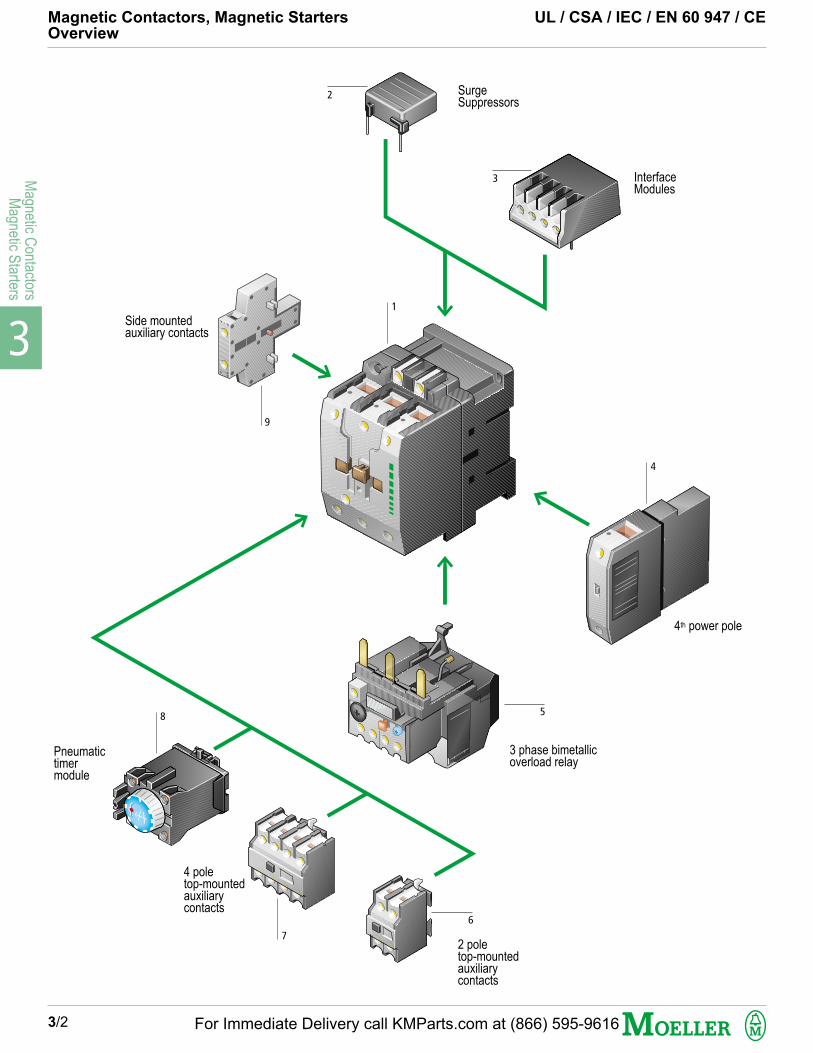
Main Contactor – Page 3/4
Main Contacts
3 & 4 power poles (DIL 00M)
3 pole + 4th pole side-mounted (DIL 0M, 1M, 2M)
Magnet System
AC Coil Range: 12 – 600 V, 50, 60, 50/60 Hz
DC Coil Range: 12 – 250 V DC
Coils also available for non-standard voltages
Added Reliability
Standard AC coils are dual voltage, each optimized at
60 Hz and 50 Hz. Example: 120 V 60 Hz / 110 V 50 Hz
Coils are also available in single voltage, single frequency;
single voltage, dual frequency and DC. Magnet system
characteristics for standard AC coils feature a broader
response range than required by standards:
Pull-in: 80 – 110%, Drop-out: 40 – 60% of coil rating.
1
Accessories – Page 3/35
Pneumatic timer module
Mechanical latch module (for DIL 00M, 00AM)
Interface modules (to enable energizing from low level sources)
Surge Suppressors
Mechanical Interlock
2,3,8 Mounting
Modularly designed system, available as components or as
completely assembled units
Provisions for both Panel and DIN rail mounting
All terminal and mounting screws, for both contactors and overload
relays, can be fastened with the identical screwdriver (Size 2
posidrive)
Finger-safe termination design for compliance with worldwide
standards
Screw-clamp terminal connections for more secure tightening of
conductors
Fast-on connectors available for more convenient control and coil
circuit tap-offs
Auxiliary Contacts – Page 3/35
Maximum 5
Top-mounted contacts, 2 & 4 pole
Side-mounted contacts, 1 & 2 pole (not for DIL 00(A)M)
Time delayed contacts, 1 N.O. & 1 N.C.
Overlapping contacts, 1 Early Make, 1 Late Break
Safety feature - Positively driven auxiliary contacts
In accordance with ZH 1/457 safety circuit requirements:
All N.O. & N.C. contacts can never be simultaneously closed, with
the exception of overlapping contacts.
For contactor type DIL 0(A)M, 1(A)M, 2(A)M: Only side-mounted
auxiliary contacts.
6,7,9
3 Phase Bimetallic Overload Relay for DIL...M
Starters – Page 3/33
Plug-in or separately mounted
Phase failure sensitive to IEC, UL & CSA
Ambient compensated to IEC, UL & CSA
Accurate and reliable tripping
Hand (supplied from factory) or automatic reset, Test button to
simulate trip, OFF button to open the N.C. contact only, Yellow trip
indicator flag
Type Z00, Z1, Z5
5
Add-on Power Pole – Page 3/36
4TH power pole can be added on to contactors type DIL 0M
through DIL 2M.
4
UL / CSA / CE / IEC / EN 60 947
DIL...M and DIL universal contactors,
ZE / Z00 / Z1 / Z5 / ZW7 overload relays are:
UL listed
CSA certified
CE marked
IEC/EN 60 947 compliant
Suitable for worldwide markets
For Immediate Delivery call KMParts.com at (866) 595-9616

3
Magnetic C
ontactorsM
agnetic Starters
NC
0
1
0
1
0
0
0
0
1
0
0
1
0
0
0
0
0
0
0
0
2
2
2
2
2
2
open/enclosedAmps
15/13.5
15/13.5
15/13.5
20/18
20/18
20/18
35/31
35/31
55/50
55/50
90/81
90/81
100/90
130
225
250
350
350
450
550
115 VHP
1/4
1/2
1/2
1/2
1/2
1
2
2
3
3
3
5
71/2
10
IEC 60 947/EN 60 947Maximum 3-phaseMotor Ratings (kW)50/60 Hz
AC-3
Rating data
UL/CSA maximumHorsepower rating (HP)50/60 Hz
Contactors – DIL...M UL / CSA / IEC / CEAC Operated
Snap-onfasteningto DIN railorpanelmounting
1 3
GeneralPurposeCont.Current
4
Standardauxiliarycontacts
5
Type
Important:Add coil voltageand frequencyfrom page 3/46 -3/47 to end oftype. See page3/5 for moredetails.
Price
2 7
DIL EEM-10
DIL EEM-01
DIL EM-10
DIL EM-01
DIL EM-4
DIL 00M 4
DIL 00M
DIL 00M-10
DIL 00M-01
DIL 00AM
DIL 00AM-10
DIL 00AM-01
DIL 0M
DIL 0AM
DIL 1M
DIL 1AM
DIL 2M
DIL 2AM
DIL 3M 80
DIL 4M 115
DIL M 185/22
DIL M 225/22
DIL M 250/22
DIL M 300/22
DIL M 400/22
DIL M 500/22
6
3-pole
3-pole
OP
EN
R
AT
ING
S
4-pole
3/4
Se
e P
ric
e L
ist
S
ee
Pri
ce
Lis
t
Se
e P
ric
e L
ist
S
ee
Pri
ce
Lis
t
Se
e P
ric
e L
ist
S
ee
Pri
ce
Lis
t
Se
e P
ric
e L
ist
S
ee
Pri
ce
Lis
t
Se
e P
ric
e L
ist
Se
e P
ric
e L
ist
S
ee
Pri
ce
Lis
t
Se
e P
ric
e L
ist
S
ee
Pri
ce
Lis
t
Se
e P
ric
e L
ist
S
ee
Pri
ce
Lis
t
Se
e P
ric
e L
ist
S
ee
Pri
ce
Lis
t
Se
e P
ric
e L
ist
1 phase 3 phase
200 VHP
3/4
1
1
1
1
2
2
3
5
5
71/2
10
15
25
230 VHP
1
11/2
11/2
11/2
11/2
2
3
5
5
71/2
10
15
15
25
200 VHP
11/2
2
2
3
3
3
71/2
71/2
10
10
15
20
25
40
50
60
75
100
125
150
230 VHP
2
3
3
3
3
3
71/2
10
10
15
20
25
30
50
60
75
100
125
150
200
460 V
HP
3
5
5
5
5
71/2
10
15
20
25
40
50
60
100
125
150
200
250
300
400
575 VHP
3
5
5
71/2
71/2
10
15
20
25
30
40
50
75
125
150
200
250
300
400
500
220 V230 VkW
1.5
2.2
2.2
2.2
2.2
3
4
5.5
7.5
11
15
18.5
22
37
55
70
75
90
125
155
380 V
440 V
kW
3
4
4
4
4
5.5
7.5
11
15
18.5
22
30
37
55
90
110
132
160
200
250
660 V690 VkW
3
4
4
5.5
5.5
7.5
11
15
18.5
22
30
37
55
90
175
215
240
286
344
344
1000 V
kW
-
-
-
-
-
-
-
-
-
-
-
-
37
55
108
108
108
132
132
132
NO
1
0
1
0
0
0
0
1
0
0
1
0
0
0
0
0
0
0
0
0
2
2
2
2
2
2
$
Note: For larger sizes please consult Moeller Electric.
For Immediate Delivery call KMParts.com at (866) 595-9616

3
Mag
netic
Con
tact
ors
Mag
netic
Sta
rter
s
1
2
UL / CSA / IEC / CE Contactors – DIL...MAC Operated
1. Overload relay Page 4/22. Interface module Page 3/433. Pneumatic Timer Module Page 3/404. Mechanical Latching Module Page 3/405. 4th Power pole (DIL 0M...2M) Page 3/36
Accessories Page 3/35
3/5
8
1. Overload Relay Page 4/22. Surge Suppressor Page 3/38
Auxiliary contacts Page 3/35Accessories Page 3/35
DIL EEM, EM
DIL 3M 80, 4M 115
1. Overload Relay Page 4/42. Surge Suppressor Page 3/38
Accessories Page 3/35
For enclosed contactor information, consult Moeller Electric Corporation.
Accessory and Ordering Guide
DIL 00M...2AM
To Order
Specify:
1 Type Number2 Accessories3 Coil Voltage
Example: 10 HP @ 460 V AC, 3 PH contactor with 1NO and 1NC standard auxiliary contacts and 120 V 60 Hz coil
How to Order
Type Number Coil Voltage
DIL 0M/11 120V 60 HZ
1
2
1
2
4
5
3
24 V 60 Hz(through DIL 4M 115) 12 V DC (DIL EM only)120 V 60 Hz / 110 V 50 Hz 24 V DC (through DIL 4M 115)208 V 60 Hz 120 V DC240 V 60 Hz / 230 V 50 Hz480 V 60 Hz / 415 V 50 Hz For a complete listing of600 V 60 Hz standard and special coils,
see page 3/46
Stock Coil Voltages
Additional Information Page
Technical Data 3/50Dimensions 3/61Overload Relays 4/2Accessories 3/35
Accessories Page 3/36
DIL M 185...500
Energization options for contactorsDIL M185...500 with electronicallycontrolled magnet systems
Directly from a PLC output:Using terminals A3 – A4 toconnect to the PLC
Using low power sources:Using terminals A10 – A11for connection to low powersources such as limitswitches, sensors, solidstate relays etc...
Conventionally:Using terminals A1 – A2for supply feed
L1N
A11
A10
A1
A2
A3
A4
L1N
A11
A10
A1
A2
A3
A4
24 VGND
L1N
A11
A10
A1
A2
A3
A4
For Immediate Delivery call KMParts.com at (866) 595-9616
3
Magnetic C
ontactorsM
agnetic Starters
NO
2
1
1
1
1
1
1
1
2
2
2
2
2
2
2
200 VHP
2
3
71/2
71/2
10
10
15
20
25
40
30
40
60
75
125
Additional Information Page
Technical Data 3/50Dimensions 3/61Overload Relays 4/2Accessories 3/35
Rating dataUL/CSA maximumHorsepower rating (HP)50/60 Hz
3-phase
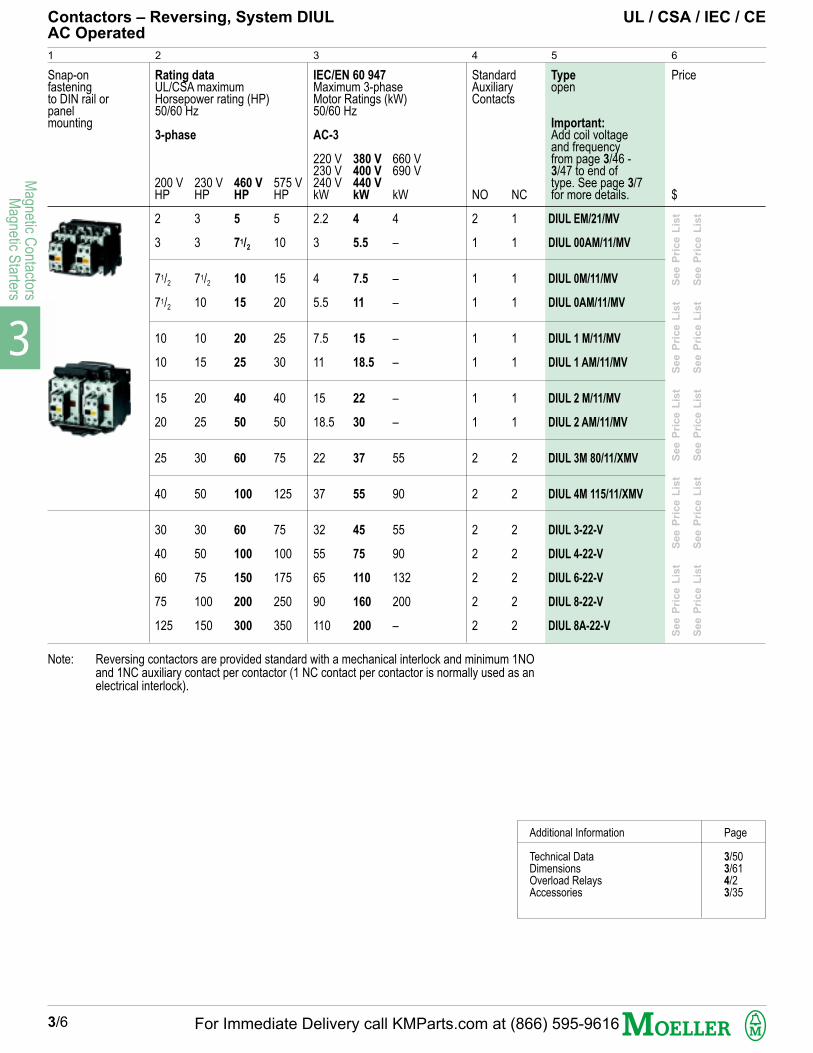
DIUL EM/21/MV
DIUL 00AM/11/MV
DIUL 0M/11/MV
DIUL 0AM/11/MV
DIUL 1 M/11/MV
DIUL 1 AM/11/MV
DIUL 2 M/11/MV
DIUL 2 AM/11/MV
DIUL 3M 80/11/XMV
DIUL 4M 115/11/XMV
DIUL 3-22-V
DIUL 4-22-V
DIUL 6-22-V
DIUL 8-22-V
DIUL 8A-22-V
1 2 63
IEC/EN 60 947Maximum 3-phaseMotor Ratings (kW)50/60 Hz
AC-3
Contactors – Reversing, System DIUL UL / CSA / IEC / CEAC Operated
Snap-onfasteningto DIN rail orpanelmounting
Note: Reversing contactors are provided standard with a mechanical interlock and minimum 1NOand 1NC auxiliary contact per contactor (1 NC contact per contactor is normally used as anelectrical interlock).
Typeopen
Important:Add coil voltageand frequencyfrom page 3/46 -3/47 to end oftype. See page 3/7for more details.
Price
$
StandardAuxiliaryContacts
54
3/6
See P
rice L
ist
S
ee P
rice L
ist
S
ee P
rice L
ist
S
ee P
rice L
ist
S
ee P
rice L
ist
See P
rice L
ist
S
ee P
rice L
ist
S
ee P
rice L
ist
S
ee P
rice L
ist
S
ee P
rice L
ist
230 VHP
3
3
71/2
10
10
15
20
25
30
50
30
50
75
100
150
460 VHP
5
71/2
10
15
20
25
40
50
60
100
60
100
150
200
300
575 VHP
5
10
15
20
25
30
40
50
75
125
75
100
175
250
350
220 V230 V240 VkW
2.2
3
4
5.5
7.5
11
15
18.5
22
37
32
55
65
90
110
380 V400 V440 VkW
4
5.5
7.5
11
15
18.5
22
30
37
55
45
75
110
160
200
660 V690 V
kW
4
–
–
–
–
–
–
–
55
90
55
90
132
200
–
NC
1
1
1
1
1
1
1
1
2
2
2
2
2
2
2
For Immediate Delivery call KMParts.com at (866) 595-9616

3
Mag
netic
Con
tact
ors
Mag
netic
Sta
rter
s
Page
Auxiliary contacts 3/35Mechanical interlock 3/40
1. Overload relays 4/2Accessories 3/35Technical information 3/50
7
3/7
UL / CSA / IEC / CE Contactors – Reversing, System DIULAC Operated
Accessory and Ordering Guide
To Order
Specify:
1 Type Number2 Accessories3 Coil Voltage
Example: 10 HP @ 460 V AC, 3 PH reversing contactors with 1NO and 1NC standard auxiliary contacts and 120 V 60 Hz coil
How to Order
Type Number Coil Voltage
DIUL 0M/11/MV 120 V 60 Hz
24 V 60 Hz (through DIUL 4M 115)120 V 60 Hz / 110 V 50 Hz208 V 60 Hz240 V 60 Hz / 230 V 50 Hz480 V 60 Hz / 415 V 50 Hz For a complete listing of600 V 60 Hz standard and special coils,
see page 3/46
For enclosed contactor information,consult Moeller Electric Corporation.
Additional Information Page
Technical Data 3/50Dimensions 3/61Overload Relays 4/2Accessories 3/35
Stock Coil Voltages
DIUL 00M - DIUL 4M 115
1
For Immediate Delivery call KMParts.com at (866) 595-9616

3
Magnetic C
ontactorsM
agnetic Starters
NC
0
1
0
1
0
0
0
0
1
0
0
1
0
0
0
0
0
0
0
0
2
2
2
2
2
2
open/enclosedAmps
15/13.5
15/13.5
15/13.5
20/18
20/18
20/18
35/31
35/31
55/50
55/50
90/81
90/81
100/90
130
225
250
350
350
450
550
115 VHP
1/4
1/2
1/2
1/2
1/2
1
2
2
3
3
3
5
71/2
10
IEC 60 947/EN 60 947Maximum 3-phaseMotor Ratings (kW)50/60 Hz
AC-3
Rating data
UL/CSA maximumHorsepower rating (HP)50/60 Hz
Contactors – DIL...M-G UL / CSA / IEC / CEDC Operated
Snap-onfasteningto DIN railorpanelmounting
1 3
GeneralPurposeContinuousCurrent
4
Standardauxiliarycontacts
5
Type
Important:Add coil voltagefrom page 3/46 -3/47 to end oftype. See page3/9 for moredetails.
Price
2 7
DIL EEM-10-G
DIL EEM-01-G
DIL EM-10-G
DIL EM-01-G
DIL EM-4-G
DIL 00M 4-G
DIL 00M-G
DIL 00M-G-10
DIL 00M-G-01
DIL 00AM-G
DIL 00AM-G-10
DIL 00AM-G-01
DIL 0M-G
DIL 0AM-G
DIL 1M-G
DIL 1AM-G
DIL 2M-G
DIL 2AM-G
DIL 3M 80
DIL 4M 115
DIL M 185/22
DIL M 225/22
DIL M 250/22
DIL M 300/22
DIL M 400/22
DIL M 500/22
6
3-pole
3-pole
OP
EN
R
AT
ING
S
4-pole
3/8
See P
rice L
ist
S
ee P
rice L
ist
S
ee P
rice L
ist
S
ee P
rice L
ist
S
ee P
rice L
ist
S
ee P
rice L
ist
S
ee P
rice L
ist
S
ee P
rice L
ist
S
ee P
rice L
ist
See P
rice L
ist
S
ee P
rice L
ist
S
ee P
rice L
ist
S
ee P
rice L
ist
S
ee P
rice L
ist
S
ee P
rice L
ist
S
ee P
rice L
ist
S
ee P
rice L
ist
S
ee P
rice L
ist
1 phase 3 phase
200 VHP
3/4
1
1
1
1
2
2
3
5
5
71/2
10
15
25
230 VHP
1
11/2
11/2
11/2
11/2
2
3
5
5
71/2
10
15
15
25
200 VHP
11/2
2
2
3
3
3
71/2
71/2
10
10
15
20
25
40
50
60
75
100
125
150
230 VHP
2
3
3
3
3
3
71/2
10
10
15
20
25
30
50
60
75
100
125
150
200
460 V
HP
3
5
5
5
5
71/2
10
15
20
25
40
50
60
100
125
150
200
250
300
400
575 VHP
3
5
5
71/2
71/2
10
15
20
25
30
40
50
75
125
150
200
250
300
400
500
220 V230 VkW
1.5
2.2
2.2
2.2
2.2
3
4
5.5
7.5
11
15
18.5
22
37
55
70
75
90
125
155
380 V
440 V
kW
3
4
4
4
4
5.5
7.5
11
15
18.5
22
30
37
55
90
110
132
160
200
250
660 V690 VkW
3
4
4
5.5
5.5
7.5
11
15
18.5
22
30
37
55
90
175
215
240
286
344
344
1000 V
kW
-
-
-
-
-
-
-
-
-
-
-
-
37
55
108
108
108
132
132
132
NO
1
0
1
0
0
0
0
1
0
0
1
0
0
0
0
0
0
0
0
0
2
2
2
2
2
2
$
Note: For larger sizes please consult Moeller Electric.
For Immediate Delivery call KMParts.com at (866) 595-9616
3
Mag
netic
Con
tact
ors
Mag
netic
Sta
rter
s
3/9
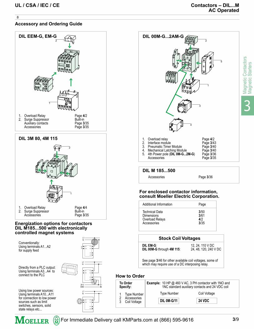
DIL EM-G: 12, 24, 110 V DCDIL 00M-G through 4M 115: 24, 48, 120, 240 V DC
See page 3/46 for other available coil voltages, some ofwhich may require use of a DC interposing relay.
Stock Coil Voltages
UL / CSA / IEC / CE Contactors – DIL...MAC Operated
1. Overload relay Page 4/22. Interface module Page 3/433. Pneumatic Timer Module Page 3/404. Mechanical Latching Module Page 3/405. 4th Power pole (DIL 0M-G...2M-G) Page 3/36
Accessories Page 3/35
8
1. Overload Relay Page 4/22. Surge Suppressor Built-in
Auxiliary contacts Page 3/35Accessories Page 3/35
DIL EEM-G, EM-G
DIL 3M 80, 4M 115
1. Overload Relay Page 4/42. Surge Suppressor Built-in
Accessories Page 3/35
For enclosed contactor information, consult Moeller Electric Corporation.
Accessory and Ordering Guide
DIL 00M-G...2AM-G
To Order
Specify:
1 Type Number2 Accessories3 Coil Voltage
Example: 10 HP @ 460 V AC, 3 PH contactor with 1NO and 1NC standard auxiliary contacts and 24 VDC coil
How to Order
Type Number Coil Voltage
DIL 0M-G/11 24 VDC
1
2
1
2
4
5
3
Additional Information Page
Technical Data 3/50Dimensions 3/61Overload Relays 4/2Accessories 3/35
Accessories Page 3/36
DIL M 185...500
Energization options for contactorsDIL M185...500 with electronicallycontrolled magnet systems
Directly from a PLC output:Using terminals A3...A4 toconnect to the PLC
Using low power sources:Using terminals A10...A11for connection to low powersources such as limitswitches, sensors, solidstate relays etc...
Conventionally:Using terminals A1...A2for supply feed
L1N
A11
A10
A1
A2
A3
A4
L1N
A11
A10
A1
A2
A3
A4
24 VGND
L1N
A11
A10
A1
A2
A3
A4
1
2
For Immediate Delivery call KMParts.com at (866) 595-9616

3
Magnetic C
ontactorsM
agnetic Starters
Contactors – DIL...M(-G) UL / CSA / IEC / CEDC Horsepower Ratings
3/10
1 32 76
Standardauxiliary contacts
Rating data
UL/CSA maximumHorsepower rating (HP)3 Poles
Type
Important:Add coil voltageand frequencyfrom page 3/46 -3/47 to end oftype.
Price
76
Type
Important:Add coil voltagefrom page 3/46 -3/47 to end oftype.
PriceThe following DIL...M(-G)
contactors are identical tothe ones shown on pages3/4 & 3/8. Below are theDC motor horsepowerratings associated to eachtype (these are not shownon pages 3/4 & 3/8). 125 V DC
HP
1
1
1
1
11/2
11/2
11/2
2
2
5
5
71/2
10
10
15
250 V DCHP
2
2
2
2
3
3
3
5
5
10
10
15
20
20
30
NO
0
1
0
0
0
1
0
0
0
0
0
0
0
0
0
NC
0
0
1
0
0
0
1
0
0
0
0
0
0
0
0
AC OPERATED
DIL 00M
DIL 00M-10
DIL 00M-01
DIL 00M 4
DIL 00AM
DIL 00AM-10
DIL 00AM-01
DIL 0M
DIL 0AM
DIL 1M
DIL 1AM
DIL 2M
DIL 2AM
DIL 3M 80
DIL 4M 115
DC OPERATED
DIL 00M-G
DIL 00M-G-10
DIL 00M-G-01
DIL 00M 4-G
DIL 00AM-G
DIL 00AM-G-10
DIL 00AM-G-01
DIL 0M-G
DIL 0AM-G
DIL 1M-G
DIL 1AM-G
DIL 2M-G
DIL 2AM-G
DIL 3M 80
DIL 4M 115
$$
See P
rice L
ist
S
ee P
rice L
ist
S
ee P
rice L
ist
S
ee P
rice L
ist
S
ee P
rice L
ist
S
ee P
rice L
ist
See P
rice L
ist
S
ee P
rice L
ist
S
ee P
rice L
ist
S
ee P
rice L
ist
S
ee P
rice L
ist
S
ee P
rice L
ist
See P
rice L
ist
S
ee P
rice L
ist
S
ee P
rice L
ist
S
ee P
rice L
ist
S
ee P
rice L
ist
S
ee P
rice L
ist
See P
rice L
ist
S
ee P
rice L
ist
S
ee P
rice L
ist
S
ee P
rice L
ist
S
ee P
rice L
ist
S
ee P
rice L
ist
For Immediate Delivery call KMParts.com at (866) 595-9616
3
Mag
netic
Con
tact
ors
Mag
netic
Sta
rter
s
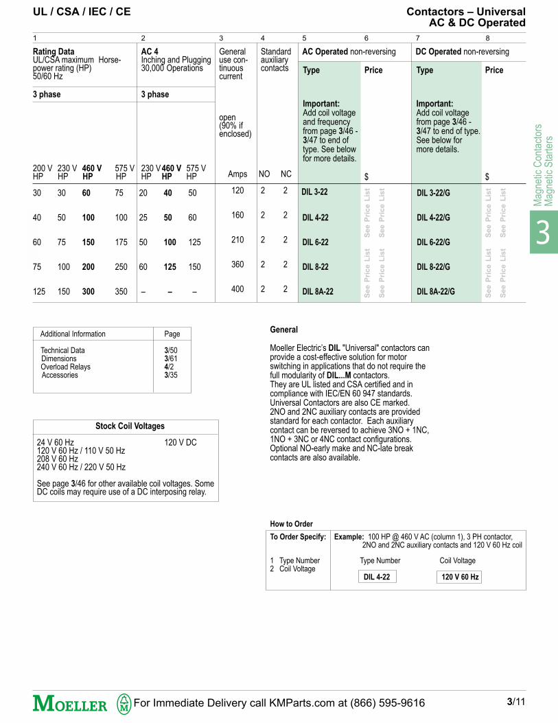
DIL 4-22
DIL 6-22
DIL 8-22
DIL 8A-22
DIL 3-22/G
DIL 4-22/G
DIL 6-22/G
DIL 8-22/G
DIL 8A-22/G
Additional Information Page
Technical Data 3/50 Dimensions 3/61 Overload Relays 4/2 Accessories 3/35
UL / CSA / IEC / CE Contactors – UniversalAC & DC Operated
3 phase
230 V460 V 575 VHP HP HP
20 40 50
25 50 60
50 100 125
60 125 150
– – –
Rating DataUL/CSA maximum Horse-power rating (HP)50/60 Hz
1 2
3 phase
200 V 230 V 460 V 575 VHP HP HP HP
30 30 60 75
40 50 100 100
60 75 150 175
75 100 200 250
125 150 300 350
AC 4Inching and Plugging30,000 Operations
3
3/11
Stock Coil Voltages
24 V 60 Hz 120 V DC120 V 60 Hz / 110 V 50 Hz208 V 60 Hz240 V 60 Hz / 220 V 50 Hz
See page 3/46 for other available coil voltages. SomeDC coils may require use of a DC interposing relay.
General
Moeller Electric’s DIL "Universal" contactors canprovide a cost-effective solution for motorswitching in applications that do not require thefull modularity of DIL...M contactors.They are UL listed and CSA certified and incompliance with IEC/EN 60 947 standards.Universal Contactors are also CE marked.2NO and 2NC auxiliary contacts are providedstandard for each contactor. Each auxiliarycontact can be reversed to achieve 3NO + 1NC,1NO + 3NC or 4NC contact configurations.Optional NO-early make and NC-late breakcontacts are also available.
Generaluse con-tinuouscurrent
open(90% ifenclosed)
Amps
120
160
210
360
400
Standardauxiliarycontacts
NO NC
2 2
2 2
2 2
2 2
2 2
4
AC Operated non-reversing
5 6
Price
$
DC Operated non-reversing
7 8
Price
$
Type
Important:
Add coil voltagefrom page 3/46 -3/47 to end of type.See below formore details.
Type
Important:
Add coil voltageand frequencyfrom page 3/46 -3/47 to end oftype. See belowfor more details.
How to Order
To Order Specify:
1 Type Number Type Number Coil Voltage2 Coil Voltage
DIL 4-22 120 V 60 Hz
Example: 100 HP @ 460 V AC (column 1), 3 PH contactor, 2NO and 2NC auxiliary contacts and 120 V 60 Hz coil
DIL 3-22
See P
rice L
ist
S
ee P
rice L
ist
See P
rice L
ist
S
ee P
rice L
ist
See P
rice L
ist
S
ee P
rice L
ist
See P
rice L
ist
S
ee P
rice L
ist
For Immediate Delivery call KMParts.com at (866) 595-9616
3
Magnetic C
ontactorsM
agnetic Starters
Starters - Ordering information
At Moeller Electric, everything starts with quality and service.
Moeller Electric's line of heavy duty starters are designed to withstand the most severe applications. They are built to meet yourrequirements, whether for installation across the street or across the ocean. Whatever the application, nearby Moeller Electric techni-cal experts stand ready to help you select the right combination of components for the job.
The following pages list the most popular starter types and accessories. If you require a modification that you do not see here,just give us a call and we will be most pleased to discuss your needs.
For quality starters and quick delivery, there is no better place to start looking than Moeller Electric.
Magnetic starter ordering information.
Moeller Electric magnetic motor starters utilize reliable Type DIL contactor(s) and precision Type Z bimetallic overload relay(s).The starter catalog numbers are a modular representation of the main starter components and make it easy to see at a glance, what isactually being provided.
For your convenience, the buildup of catalog numbers for the most frequently used starters are explained on this page.
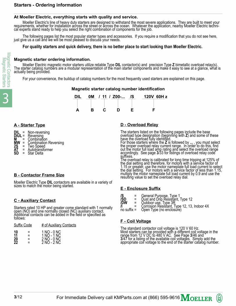
Magnetic starter catalog number identification
DIL 0M / 11 / Z00-... /S 120V 60H z
A B C D E F
A - Starter Type
DIL = Non-reversingDIUL = ReversingM = CombinationMW = Combination Reversing2S = Two SpeedAT = AutotransformerSD = Star Delta
B - Contactor Frame Size
Moeller Electric Type DIL contactors are available in a variety ofsizes to match the motor being started.
C - Auxiliary Contact
Starters rated 10 HP and greater come standard with 1 normallyopen (NO) and one normally closed (NC) auxiliary contact.Additional contacts can be added in the field or specified asfollows:
Suffix Code # of Auxiliary Contacts
10 = 1 NO - 0 NC11 = 1 NO - 1 NC20 = 2 NO - 0 NC22 = 2 NO - 2 NC
D - Overload Relay
The starters listed on the following pages include the baseoverload type designation (beginning with Z) and some of thesehave the overload fully identified.For those starters where the Z is followed by ... , you must selectthe proper overload relay current range. In order to do this, findout the motor full load amp rating and select the overload rangeaccordingly. See page 3/33 for listings of overload relay codesuffixes.The overload relay is calibrated for long time tripping at 125% ofthe dial setting and therefore, for motors with a service factor of1.15 or greater, use the motor nameplate full load current to selectthe dial setting. For motors with a service factor of less than 1.15,multiply the motor nameplate full load current by 0.9 and use theresulting value to set the overload relay dial.
E - Enclosure Suffix
/S = General Purpose, Type 1/SD = Dust and Drip Resistant, Type 12/DW = Outdoor use, Type 3R/I = Corrosion Resistant, Type 12, 13, Indoor 4Xno suffix = Open Type (no enclosure)
F - Coil Voltage
The standard contactor coil voltage is 120 V 60 Hz.Most starters can be provided with a different coil voltage in therange from 12 V DC to 480 V AC. See Page 3/46 and3/47 for a listing of the available coil voltages. Simply add theappropriate coil voltage to the end of the starter catalog number.
3/12 For Immediate Delivery call KMParts.com at (866) 595-9616

3
Mag
netic
Con
tact
ors
Mag
netic
Sta
rter
s
Starters - Ordering information
Selecting and Completing the Type Number
The following is an explanation of the HOW TO ORDER box.Each box contains an ordering example. For this example (from page 3/12), suppose a full-voltage, non-reversing, non-combinationstarter in a general purpose Type 1 enclosure and with a contactor coil voltage of 120 V 60 Hz.
How to Order
To Order Specify:
Type NumberOverload Relay Suffix (page 3/33)Enclosure SuffixCoil Voltage (page 3/46)Accessories
Type Number Example: DIL 0M/11/Z00-16/S 120 V 60 Hz
Type Overload Relay Suffix Enclosure Suffix Coil Voltage
DIL 0M/11/Z00- 16 /S 120 V 60 Hz
DCBA
A Type
This is the basic starter type. It includes:
DIL = Non-reversing, across-the-line starter.0M = Contactor frame size (10 HP @ 460 V AC, 3-ph). Accessories such as control
transformers are chosen according to contactor frame size./11 = Auxiliary contacts- 1 NO, 1 NC./Z00- = Type Z00 overload relay (motor current setting range suffix to be added).
B Overload Relay Suffix
Z00- = This part requires completion by adding a suffix code from page 3/33.
Example: For the 10 HP motor at 460 V AC, 3-ph, the motor full load current is 14 (if possible,use actual nameplate rating). Following the guidelines found on the previous page,select an overload setting range within the Z00- type from page 3/33 that includesthe 14 A motor FLC. The first choice would be the Z00-16 with an adjusted range of10 to 16 A. The suffix number to be inserted into the starter catalog number is themaximum of the setting range, or in this case, 16.
C Enclosure Suffix
/S = General purpose indoor, Type 1/SD = Dust and drip resistant, Type 12./DW = Weather resistant outdoor, Type 3R./I = Corrosion resistant non-metallic indoor, Type 4X or 13.
For the starter in question, therefore, the correct enclosure suffix would be /S.Other enclosure types are also available - contact Moeller Electric.
D Coil Voltage
From page 3/46, select the required coil voltage; in this case, 120 V 60 Hz.
3/13For Immediate Delivery call KMParts.com at (866) 595-9616

3
Magnetic C
ontactorsM
agnetic Starters
Se
e
Pr i
ce
L
ist
S
ee
P
r ic
e
Lis
t
Se
e
Pri
ce
L
ist
S
ee
P
ric
e
Lis
t
Without Enclosure
Price$
11
11
11
11
11111 S
ee
P
r ic
e
Lis
t
Se
e
Pr i
ce
L
ist
Se
e
Pr i
ce
L
ist
S
ee
P
r ic
e
Lis
t
Se
e
Pr i
ce
L
ist
S
ee
P
r ic
e
Lis
t
Se
e
Pr i
ce
L
ist
S
ee
P
r ic
e
Lis
t
Se
e
Pr i
ce
L
ist
S
ee
P
r ic
e
Lis
t
Se
e
Pr i
ce
L
ist
S
ee
P
r ic
e
Lis
t
DIL EEM-10/ZE-...DIL EM-10/ZE-...
DIL 00M-10/Z00-...DIL 00AM-10/Z00-...
DIL 0M/11/Z00-...DIL 0AM/11/Z00-...
DIL 1M/11/Z1-40DIL 1AM/11/Z1-40
DIL 2M/11/Z1-40DIL 2M/11/Z1-57DIL 2AM/11/Z1-57DIL 2AM/11/Z1-63DIL 2AM/11/Z1-75
See P
rice L
ist
See P
rice L
ist
See P
rice L
ist
See P
rice L
ist
See P
rice L
ist
See P
rice L
ist
See P
rice L
ist
See P
rice L
ist
See P
rice L
ist
See P
rice L
ist
See P
rice L
ist
See P
rice L
ist
See P
rice L
ist
See P
rice L
ist
See P
rice L
ist
See P
rice L
ist
See P
rice L
ist
See P
rice L
ist
See P
rice L
ist
See P
rice L
ist
See P
rice L
ist
See P
rice L
ist
See P
rice L
ist
See P
rice L
ist
See P
rice L
ist
See P
rice L
ist
See P
rice L
ist
See P
rice L
ist
See P
rice L
ist
See P
rice L
ist
See P
rice L
ist
See P
rice L
ist
See P
rice L
ist
See P
rice L
ist
See P
rice L
ist
See P
rice L
ist
See P
rice L
ist
See P
rice L
ist
See P
rice L
ist
See P
rice L
ist
DIL EEM-10/ZE-...DIL EM-10/ZE-...DIL 00M-10/Z00-...DIL 00AM-10/Z00-...
DIL 0M/11/Z00-...DIL 0AM/11/Z00-24DIL 0M/11/Z1-40DIL 0AM/11/Z1-40
DIL 1M/11/Z1-40DIL 1AM/11/Z1-40DIL 1AM/11/Z1-57
DIL 2M/11/Z1-57DIL 2AM/11/Z1-57DIL 2AM/11/Z1-63DIL 2AM/11/Z1-75
DIL 3M 80/11/Z5-100DIL 4M 115/11/Z5-...
DIL 3-22/Z4-100DIL 4-22/Z4-...2)
DIL 6-22/Z4-...2)
DIL 8-22/Z4-2403)
DIL 8-22/ZW7-2903)
DIL 8A-22/ZW7-4003)
0000
1111
111
1111
11
222222
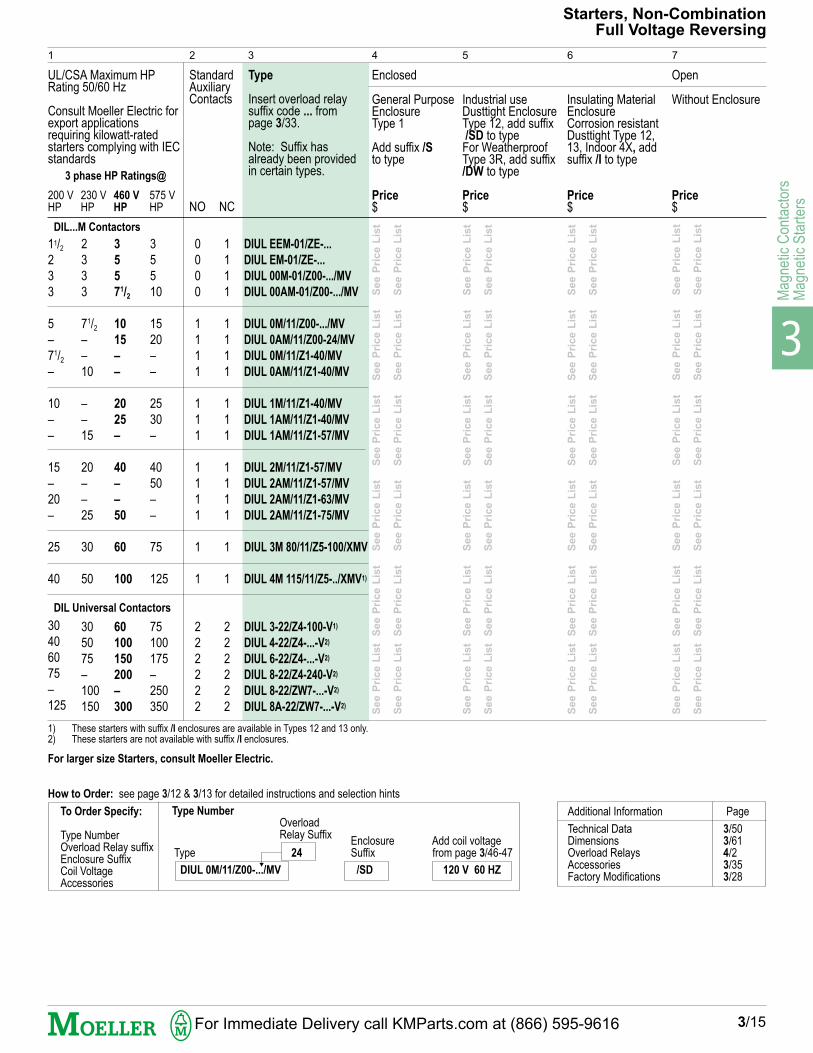
Starters, Non-CombinationFull Voltage Non-Reversing
1
UL/CSA Maximum HPRating 50/60 Hz
Consult Moeller Electric forexport applicationsrequiring kilowatt-ratedstarters complying with IECstandards
200 V 230 V 460 V 575 VHP HP HP HP
StandardAuxiliaryContacts
NO NC
Type1)
Insert overload relaysuffix code ... frompage 3/33.
Note: Suffix hasalready beenprovided in certaintypes.
Enclosed
General PurposeEnclosureType 1
Add suffix /Sto type
Price$
Industrial useDusttight EnclosureType 12, add suffix /SD to typeFor WeatherproofType 3R, add suffix/DW to type
Price$
Insulating MaterialEnclosureCorrosion resistantDusttight Type 12,13, Indoor 4X, addsuffix /I to type
Price$
Open
11/2233
5–71/2
–
10––
15–20–
2540
30406075–125
2333
71/2
––10
––15
20––25
3050
305075–100150
35571/2
1015––
2025–
40––50
60100
60100150200–300
35510
1520––
2530–
4050––
75125
75100175–250350
1111
1111
111
1111
11
222222
115VHP
200 VHP
230 VHP
1/41/2
1/2
1
22
33
3–5––
3 phase HP Ratings@
1 phase HP Ratings @
3/4
1
12
23
55
–71/2
–10–
111/2
11/22
33
571/2
–10––15
1) UL listed overload relays Types ZE, Z00, Z1 and Z5 are normally supplied with the starters on this page. For more flexibility,they can also be field installed. Consult Moeller Electric for additional details.
2) These starters with suffix /I enclosures are available in Types 12 and 13 only.3) These starters are not available with suffix /I enclosures.
00
00
11
11
11111
3/14
2 3 4 5 6 7
DIL Universal Contactors
DIL...M Contactors
DIL...M Contactors
Additional Information Page
Technical Data 3/50Dimensions 3/61Overload Relays 4/2Accessories 3/35Factory Modifications 3/28
How to Order: see page 3/12 & 3/13 for detailed instructions and selection hints
Catalog Number
Type Overload Enclosure Add coil voltageRelay Suffix Suffix from page 3/46-47
DIL 0M/11/Z00- 10 /S 120 V 60 Hz
To Order Specify:
Type NumberOverload Relay suffixEnclosure SuffixCoil VoltageAccessories
For Immediate Delivery call KMParts.com at (866) 595-9616
3
Mag
netic
Con
tact
ors
Mag
netic
Sta
rter
s
See P
rice L
ist
See P
rice L
ist
S
ee P
rice L
ist
S
ee P
rice L
ist
S
ee P
rice L
ist
S
ee P
rice L
ist
See P
rice L
ist
See P
rice L
ist
S
ee P
rice L
ist
S
ee P
rice L
ist
S
ee P
rice L
ist
S
ee P
rice L
ist
See P
rice L
ist
See P
rice L
ist
S
ee P
rice L
ist
S
ee P
rice L
ist
S
ee P
rice L
ist
S
ee P
rice L
ist
See P
rice L
ist
See P
rice L
ist
S
ee P
rice L
ist
S
ee P
rice L
ist
S
ee P
rice L
ist
S
ee P
rice L
ist
See P
rice L
ist
See P
rice L
ist
S
ee P
rice L
ist
S
ee P
rice L
ist
S
ee P
rice L
ist
S
ee P
rice L
ist
See P
rice L
ist
See P
rice L
ist
S
ee P
rice L
ist
S
ee P
rice L
ist
S
ee P
rice L
ist
S
ee P
rice L
ist
See P
rice L
ist
See P
rice L
ist
S
ee P
rice L
ist
S
ee P
rice L
ist
S
ee P
rice L
ist
S
ee P
rice L
ist
See P
rice L
ist
See P
rice L
ist
S
ee P
rice L
ist
S
ee P
rice L
ist
S
ee P
rice L
ist
S
ee P
rice L
ist
DIUL EEM-01/ZE-...
DIUL EM-01/ZE-...
DIUL 00M-01/Z00-.../MV
DIUL 00AM-01/Z00-.../MV
DIUL 0M/11/Z00-.../MV
DIUL 0AM/11/Z00-24/MV
DIUL 0M/11/Z1-40/MV
DIUL 0AM/11/Z1-40/MV
DIUL 1M/11/Z1-40/MV
DIUL 1AM/11/Z1-40/MV
DIUL 1AM/11/Z1-57/MV
DIUL 2M/11/Z1-57/MV
DIUL 2AM/11/Z1-57/MV
DIUL 2AM/11/Z1-63/MV
DIUL 2AM/11/Z1-75/MV
DIUL 3M 80/11/Z5-100/XMV
DIUL 4M 115/11/Z5-../XMV1)
DIUL 3-22/Z4-100-V1)
DIUL 4-22/Z4-...-V2)
DIUL 6-22/Z4-...-V2)
DIUL 8-22/Z4-240-V2)
DIUL 8-22/ZW7-...-V2)
DIUL 8A-22/ZW7-...-V2)
Additional Information Page
Technical Data 3/50Dimensions 3/61Overload Relays 4/2Accessories 3/35Factory Modifications 3/28
Type 24
1
1
1
1
1
1
1
1
1
1
1
1
1
1
1
1
1
2
2
2
2
2
2
1
UL/CSA Maximum HPRating 50/60 Hz
Consult Moeller Electric forexport applicationsrequiring kilowatt-ratedstarters complying with IECstandards
200 V 230 V 460 V 575 VHP HP HP HP
StandardAuxiliaryContacts
NO NC
Type
Insert overload relaysuffix code ... frompage 3/33.
Note: Suffix hasalready been providedin certain types.
Enclosed
General PurposeEnclosureType 1
Add suffix /Sto type
Price$
Industrial useDusttight EnclosureType 12, add suffix /SD to typeFor WeatherproofType 3R, add suffix/DW to type
Price$
Insulating MaterialEnclosureCorrosion resistantDusttight Type 12,13, Indoor 4X, addsuffix /I to type
Price$
Without Enclosure
Price$
Open
11/22
3
3
5
–
71/2
–
10
–
–
15
–
20
–
25
40
30
40
60
75
–
125
2
3
3
3
71/2
–
–
10
–
–
15
20
–
–
25
30
50
30
50
75
–
100
150
3
5
5
71/2
10
15
–
–
20
25
–
40
–
–
50
60
100
60
100
150
200
–
300
3
5
5
10
15
20
–
–
25
30
–
40
50
–
–
75
125
75
100
175
–
250
350
0
0
0
0
1
1
1
1
1
1
1
1
1
1
1
1
1
2
2
2
2
2
2
To Order Specify:
Type NumberOverload Relay suffixEnclosure SuffixCoil VoltageAccessories
How to Order: see page 3/12 & 3/13 for detailed instructions and selection hints
1) These starters with suffix /I enclosures are available in Types 12 and 13 only.2) These starters are not available with suffix /I enclosures.
For larger size Starters, consult Moeller Electric.
Type Number
OverloadRelay Suffix
Enclosure Add coil voltageSuffix from page 3/46-47
DIUL 0M/11/Z00-.../MV /SD 120 V 60 HZ
2 3 4 5 6 7
Starters, Non-CombinationFull Voltage Reversing
DIL...M Contactors
DIL Universal Contactors
3/15
3 phase HP Ratings@
For Immediate Delivery call KMParts.com at (866) 595-9616
3
Magnetic C
ontactorsM
agnetic Starters
2S2W 00M/Z00-.../Z00-.../S2S2W 00AM/Z00-.../Z00-.../S2S2W 0M/Z00-.../Z00-.../S2S2W 0M/Z1-.../Z00-.../S2S2W 0AM/Z00-.../Z1-.../S2S2W 0AM/Z1-.../Z1-.../S2S2W 1M/Z1-.../Z1-.../S2S2W 1AM/Z1-.../Z1-.../S2S2W 2M/Z1-.../Z1-.../S2S2W 2AM/Z1-.../Z1-.../S
2S2W 3-22/Z4-.../Z1-.../S2S2W 4-22/Z4-.../Z1-.../S2S2W 6-22/Z4-.../Z4-.../S2S2W 8-22/Z4-.../Z4-.../S2S2W 8-22/ZW7-.../Z4-.../S2S2W 8A-22/ZW7-.../Z4-.../S2S2W 8A-22/ZW7-.../ZW7-.../S
2S2W 00M/Z00-.../Z00-.../S2S2W 00AM/Z00-.../Z00-.../S2S2W 0M/Z00-.../Z00-.../S2S2W 0AM/Z00-.../Z00-.../S2S2W 1M/Z1-.../Z1-.../S2S2W 1AM/Z1-.../Z1-.../S2S2W 2M/Z1-.../Z1-.../S2S2W 2AM/Z1-.../Z1-.../S
2S2W 3-22/Z1-.../Z1-.../S2S2W 4-22/Z4-.../Z1-.../S2S2W 6-22/Z4-.../Z1-.../S2S2W 8-22/Z4-.../Z1-.../S2S2W 8-22/Z4-.../Z4-.../S2S2W 8-22/ZW7-.../Z4-.../S2S2W 8A-22/ZW7-.../Z4-.../S
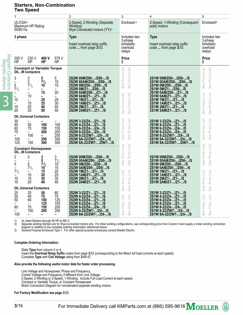
Starters, Non-CombinationTwo Speed
1
UL/CSA1)
Maximum HP Rating50/60 Hz
3 phase
200 V 230 V 460 V 575 VHP HP HP HP
2-Speed, 2-Winding (SeparateWinding)Wye-Connected motors (YY)2)
Type
Insert overload relay suffixcode ... from page 3/33.
Enclosed 3)
Includes two3-phasebimetallicoverloadrelays
Price$
3–571/2
––10–1520
30406075–100125
2–5–71/2
–1015
253050–60–100
3371/2
––10–152025
–5075–100–150
2–571/2
–101520
254060–75100–
571/2
10–15–20254050
–100150200–250300
3571/2
1015203040
5075100125150200–
51015–20–25304050
–100150200250300350
371/2
101520253040
6075125150200250–
Constant or Variable Torque
1) UL listed Starters through 50 HP at 460 V.2) Separate winding Starters are for Wye-Connected motors only. For other winding configurations, use corresponding price from Column 5 and supply a motor winding connection
diagram in addition to the complete ordering information referenced below.3) General Purpose Enclosure Type 1. For other special purpose enclosures consult Moeller Electric.
3/16
2 3 4 5
Enclosed3)
Includes two3-phasebimetallicoverloadrelays
Price$
2-Speed, 1-Winding (Consequentpole) motors
Type
Insert overload relay suffixcode ... from page 3/33.
Constant Horsepower
2S1W 00M/Z00-.../Z00-.../S2S1W 00AM/Z00-.../Z00-.../S2S1W 0M/Z00-.../Z00-.../S2S1W 0M/Z1-.../Z00-.../S2S1W 0AM/Z00-.../Z1-.../S2S1W 0AM/Z1-.../Z1-.../S2S1W 1M/Z1-.../Z1-.../S2S1W 1AM/Z1-.../Z1-.../S2S1W 2M/Z1-.../Z1-.../S2S1W 2AM/Z1-.../Z1-.../S
2S1W 3-22/Z4-.../Z1-.../S2S1W 4-22/Z4-.../Z1-.../S2S1W 6-22/Z4-.../Z4-.../S2S1W 8-22/Z4-.../Z4-.../S2S1W 8-22/ZW7-.../Z4-.../S2S1W 8A-22/ZW7-.../Z4-.../S2S1W 8A-22/ZW7-.../ZW7-.../S
2S1W 00M/Z00-.../Z00-.../S2S1W 00AM/Z00-.../Z00-.../S2S1W 0M/Z00-.../Z00-.../S2S1W 0AM/Z00-.../Z00-.../S2S1W 1M/Z1-.../Z1-.../S2S1W 1AM/Z1-.../Z1-.../S2S1W 2M/Z1-.../Z1-.../S2S1W 2AM/Z1-.../Z1-.../S
2S1W 3-22/Z1-.../Z1-.../S2S1W 4-22/Z4-.../Z1-.../S2S1W 6-22/Z4-.../Z1-.../S2S1W 8-22/Z4-.../Z1-.../S2S1W 8-22/Z4-.../Z4-.../S2S1W 8-22/ZW7-.../Z4-.../S2S1W 8A-22/ZW7-.../Z4-.../S
Complete Ordering Information:
State Type from column 2 or 4.Insert the Overload Relay Suffix codes from page 3/33 (corresponding to the Motor full load currents at each speed).Complete Type with Coil Voltage rating from 3/46-47.
Also provide the following useful motor data for faster order processing:
Line Voltage and Horsepower, Phase and Frequency.Control Voltage and Frequency, if different from Line Voltage.2-Speed, 2-Winding or 2-Speed, 1-Winding. Include Full Load Current at each speed.Constant or Variable Torque, or Constant Horsepower.Motor Connection Diagram for nonstandard separate winding motors.
For Factory Modification see page 3/28.
DIL...M Contactors
DIL Universal Contactors
DIL...M Contactors
DIL Universal Contactors
See P
rice L
ist
S
ee P
rice L
ist
S
ee P
rice L
ist
S
ee P
rice L
ist
S
ee P
rice L
ist
S
ee P
rice L
ist
See P
rice L
ist
S
ee P
rice L
ist
S
ee P
rice L
ist
S
ee P
rice L
ist
S
ee P
rice L
ist
S
ee P
rice L
ist
See P
rice L
ist
S
ee P
rice L
ist
S
ee P
rice L
ist
S
ee P
rice L
ist
S
ee P
rice L
ist
S
ee P
rice L
ist
See P
rice L
ist
S
ee P
rice L
ist
S
ee P
rice L
ist
S
ee P
rice L
ist
S
ee P
rice L
ist
S
ee P
rice L
ist
For Immediate Delivery call KMParts.com at (866) 595-9616
3
Mag
netic
Con
tact
ors
Mag
netic
Sta
rter
s
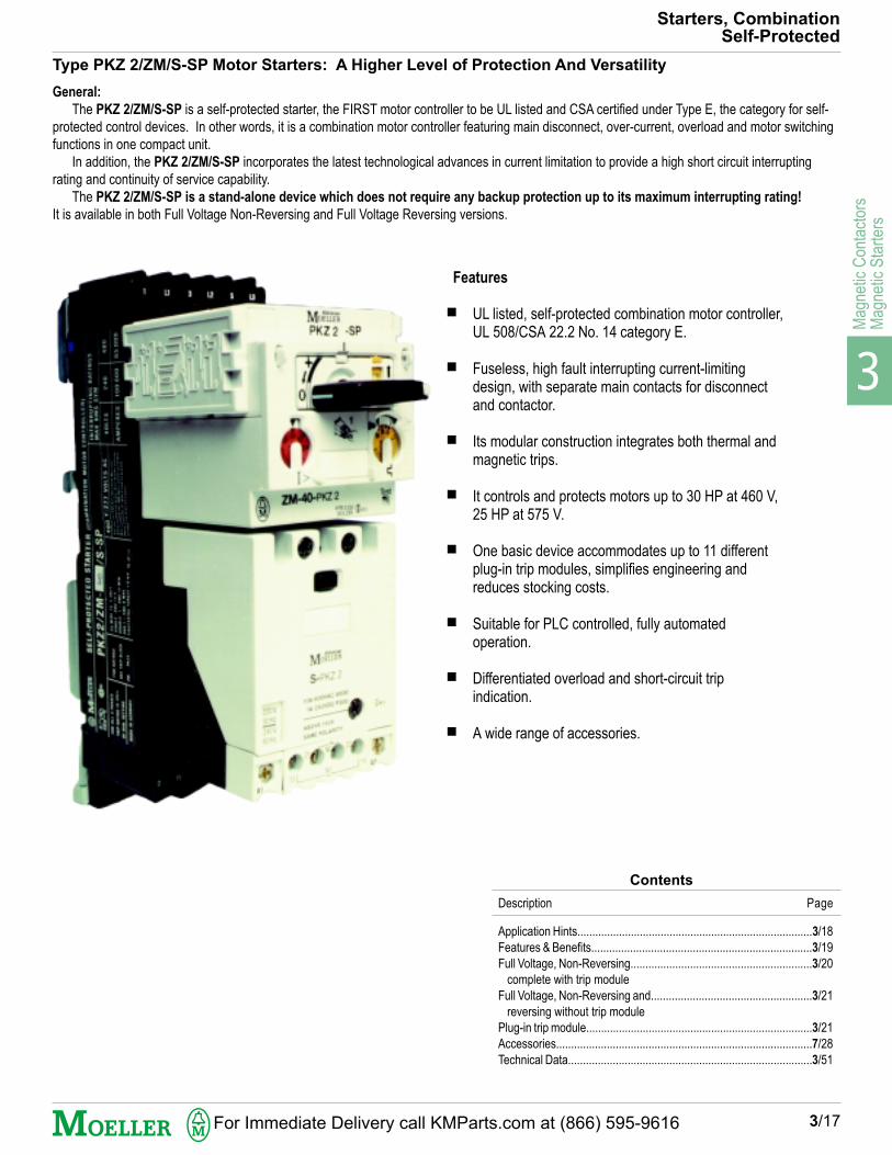
Starters, CombinationSelf-Protected
Type PKZ 2/ZM/S-SP Motor Starters: A Higher Level of Protection And Versatility
General:
The PKZ 2/ZM/S-SP is a self-protected starter, the FIRST motor controller to be UL listed and CSA certified under Type E, the category for self-
protected control devices. In other words, it is a combination motor controller featuring main disconnect, over-current, overload and motor switching
functions in one compact unit.
In addition, the PKZ 2/ZM/S-SP incorporates the latest technological advances in current limitation to provide a high short circuit interrupting
rating and continuity of service capability.
The PKZ 2/ZM/S-SP is a stand-alone device which does not require any backup protection up to its maximum interrupting rating!
It is available in both Full Voltage Non-Reversing and Full Voltage Reversing versions.
Features
UL listed, self-protected combination motor controller,UL 508/CSA 22.2 No. 14 category E.
Fuseless, high fault interrupting current-limitingdesign, with separate main contacts for disconnectand contactor.
Its modular construction integrates both thermal andmagnetic trips.
It controls and protects motors up to 30 HP at 460 V,25 HP at 575 V.
One basic device accommodates up to 11 differentplug-in trip modules, simplifies engineering andreduces stocking costs.
Suitable for PLC controlled, fully automatedoperation.
Differentiated overload and short-circuit tripindication.
A wide range of accessories.
3/17
Contents
Description Page
Application Hints...............................................................................3/18
Features & Benefits..........................................................................3/19
Full Voltage, Non-Reversing.............................................................3/20
complete with trip module
Full Voltage, Non-Reversing and......................................................3/21
reversing without trip module
Plug-in trip module............................................................................3/21
Accessories......................................................................................7/28
Technical Data..................................................................................3/51
For Immediate Delivery call KMParts.com at (866) 595-9616

3
Magnetic C
ontactorsM
agnetic Starters
Starters – CombinationSelf-protected
As per the intent of NEC Article 430, the self-protected control device willperform the functions of Motor Disconnecting Means (Part J), Motor Branch-Circuit, Short-Circuit and Ground-Fault Protection (Part D), Motor Controller(Part G) and Motor Overload Protection (Part C). Up to the maximum ratedshort circuit current available, NO upstream circuit breaker or set of fuses isrequired.The PKZ 2/ZM-.../S-SP has 2 sets of main contacts, both current-limiting indesign. This provides it with a high interrupting rating and the capability to
protect itself against damage under fault conditions. No contact welding canensue thus providing for continuity of service.Each unit consists of a basic frame (disconnect switch and contactor) rated toswitch a motor load of 30 HP @ 460 V AC. Eleven plug-in trip modules areavailable to cover motor loads ranging from fractional HP sizes through 30 HP@ 460 V AC. As a result, stocking of parts is minimized and use of the starterfor other motor loads may be as simple as plugging-in a new trip module andsetting the trip response dials.
3/18
Choose the PKZ 2/ZM-.../S-SP starter for maximum protection and flexibility.
K UL Listed for use on circuits capable of delivering 65,000 RMS Sym amps @480Y/277 V AC and 42,000 RMS Sym amps @ 600Y/347 V AC
K NO backup short circuit protection required (replaces the fuses or circuit breakers required by other conventional starters)
K Plug-in trip modules can be removed/installed without disturbing power wiring
K Field-adjustable, coordinated and sealable settings for motor overload and short circuit trip response
K Compact design allows installation in hard-to-fit areas
K Exceeds IEC "Type 2" coordination without the need for additional fuses or circuit breaker
K Removal of trip block (for maintenance or servicing) provides visible electrical isolation gap between line disconnecting and contactor portions
K All live parts (including terminals) are shrouded against accidental contact ("finger proof" per IEC 536), even with the plug-in trip module
removed
K Maximum continuity of service (protects itself against damage from fault currents)
All-In-One Starter Eliminates Upstream Circuit Breaker or Fuses
Application:
Motor Feeder
Motor Feeder
Short-Circuit andGround-Fault Protection
Motor DisconnectingMeans
Motor Branch-CircuitShort-Circuit andGround-Fault Protection
Motor Circuit Conductor
Motor Controller
Motor Control Circuits
MotorOverload Protection
Motor
Thermal Protection
Secondary ControllerSecondary Conductors
SecondaryResistor
PKZ 2/ZM-...S-SP
Self-protectedcombination MotorController
Part B430-24
430-25 and 430-26
Part E
Part E
Part J
Part D
Part B
Part G
Part F
Part C
Part A
Part C
Part BSec 430-23
Sec 430-23Part B
and Art. 470
Diagram 430-1 from NEC Article 430
For Immediate Delivery call KMParts.com at (866) 595-9616

3
Mag
netic
Con
tact
ors
Mag
netic
Sta
rter
s
a Both field wiring terminals on the line side (Disconnect) and load side (Contactor) have large Service Entrance spacings typical of molded case circuit breakers.
b The Main Disconnect isolating contacts are current limiting in design.
c Visible, "finger-touch-proof" open circuit power path when Trip Module is removed.
d The Contactor Motor Switching contacts are also current limiting in design and significantly enhance the device's overall interrupting ability.
e The Contactor comes standard with 1 NO and 1 NC auxiliary contacts. 2 NO also available.
f The Trip Module can be set and then sealed with a wire lock.
g Padlockable Handle with ON, OFF and TRIP (+) indication.
h Field-interchangeable plug-in Motor Protective Trip Modules with Coordinated Overload and Short-Circuit protection built-in.
i Adjustable magnetic trip dial, range: 8.5 – 14 times Trip Module rating.
j Adjustable thermal trip dial, range: 0.6 – 1 times Trip Module rating (set to Motor FLC).
k Test-to-trip slot.
l Coding feature to differentiate Trip Modules.
m Short-circuit trip indicator K-AGM-PKZ 2 provides visual indication of short circuit trip condition and differentiation between short circuit and general trip due tooverload and/or voltage trips.
The PKZ 2/ZM-.../S-SP Self-Protected Starter comes standard as a one piece construction featuring a Main Disconnect and a Contactor. The unit can be eitherpanel or rail mounted. Integral power takeoffs are provided between the Disconnect and Contactor for control circuit feed. Adjustable Motor protective thermal-magnetic Trip modules are set in accordance with the Motor Full Load Current and plugged directly into the base of the Disconnect. Trip modules and accessoriescan all be field installed for maximum versatility.The Main Disconnect and Contactor modules can also be separately mounted. This is particularly suitable for Full Voltage Reversing applications which combinethe PKZ 2-SP disconnect with two mechanically interlocked S-PKZ 2 contactors (see page 3/21).
3/19
Starters – CombinationSelf-protected
ZMR-...-PKZ 2
Trip Module Type ZMR
Under overload and short circuit fault conditions the standard trip module will open the Main Disconnect portionof the PKZ 2 Self-Protected starter, much like the operation of an inverse time molded case circuit breaker.As an option, the trip module Type ZMR can be provided. It features a set of auxiliary contacts which areactuated under overload conditions. Similar to the operation of an overload relay in a conventional combinationcontroller, the N.C. contact can be used to de-energize the contactor coil circuit in the event of an overload andthe N.O. contact can be used to annunciate the condition. A short circuit fault will trip open the Main disconnectinstantaneously just like the standard trip module.The ZMR module is ideal for applications which need to take full advantage of the Self-Protected Starter'scapabilities over conventional combination controllers, but wish to retain the operating features of a conventionaloverload relay in a starter. See page 7/26 for further info.
a
b
c
d
e
f
g
h
i
j
k
l
m
For Immediate Delivery call KMParts.com at (866) 595-9616

3
Magnetic C
ontactorsM
agnetic Starters
InsulatingMaterialEnclosureCorrosionresistantDusttight
Type 12Add suffix /Ito type2)
Industrial useDusttightEnclosure
Type 12Add suffix /SDto typeWeatherproofType 3RAdd suffix/DW to type
OpenAdjustable currentrange
PKZ 2/ZM-0.6/S-SP
PKZ 2/ZM-1/S-SP
PKZ 2/ZM-1.6/S-SP
PKZ 2/ZM-2.4/S-SP
PKZ 2/ZM-4/S-SP
PKZ 2/ZM-6/S-SP
PKZ 2/ZM-10/S-SP
PKZ 2/ZM-16/S-SP
PKZ 2/ZM-25/S-SP
PKZ 2/ZM-32/S-SP
PKZ2/ZM-40/S-SP
200 VHP
1/2
111/22371/2
1010
230 VHP
1/3
1/2
111/23571/2
1015
575 VHP
1/2
111/23571/2
1025––
A 30 HP, 460 V self protected combina-tion motor controller: PKZ 2-SP installedin a NEMA 1 enclosure with fused controltransformer, extra auxiliary contact andpilot devices
Standard FeaturesUL listed/CSA certified, self-protected combination motor controller, UL 508/CSA 22.2 No.14 Type E.Main Disconnect and Contactor modules rated max 42 A, 30 HP @ 460 V AC; max. 27 A, 25 HP @ 575 V AC.Stand-alone device, no back-up overcurrent protection required up to its full interrupting rating, 100/65/42 kA @ 240/480/600 V AC.Continuity of service (protects itself against damage under fault conditions).For additional safety, plug-in trip module, which creates an open circuit path to the motor when removed.Adjustable thermal and magnetic trips; built-in phase loss differential trip.Built-in 1 NO & 1 NC auxiliary contacts in the contactor portion. 2 N.O. also available.Electrical life: 1 million operations, AC-3 (30 HP at 460 V AC)Adapter plate for rail or panel mounting.Tap-off terminals on load side of disconnect for easy control circuit feed.Full range of accessories including voltage trips, standard and differentiated trip indicating auxiliary contacts, remote control drive.Environmentally safe! No cadmium, asbestos, mercury, PCB's. No Fluorocarbons produced during manufacture.Enclosed starters provided with door interlocking and padlockable handle.
Adjust-ableThermalsettings(set tomotorFLC)1)
Adjust-ableInstanta-neousTripRange
1) Set bimetal trips (yellow dial) to motor FLC– Tripping current = 125% of setting– For motors of Service Factor 1.0, set dial to 0.9 of Motor FLC setting– Ambient compensated– Phase failure sensitive
2) For type 4X, consult Moeller Electric.
Type
When orderingSpecify:- Type- Enclosure Suffixfrom columns 6, 7or 8, if applicable- Coil voltageand frequency(See example atbottom of page)
Standard coilvoltages:AC: 24, 120, 208,240,480, 600 60 HzDC: 24 V
Enclosed
GeneralPurposeEnclosure
Type 1Add suffix/S to type
460 V
HP
1/2
3/4
1
2
3
5
10
20
20
30
Amps
0.4-0.60.6-1.01.0-1.61.6-2.42.4-4.04.0-6.06-1010-1616-2724-3232-42
Amps
5-88-1414-2220-3535-5550-8080-140130-220200-350275-425350-500
Starters – CombinationSelf-protected, Full Voltage Non-Reversing
1 2 3
3/20
4 5 6 7 8
UL/CSAMaximum HPRating 50/60 Hz3 Phase
Se
e P
r ic
e L
ist
S
ee
P
r ic
e L
ist
Se
e P
r ic
e L
ist
S
ee
P
r ic
e L
ist
Se
e P
r ic
e L
ist
S
ee
P
r ic
e L
ist
Se
e P
r ic
e L
ist
S
ee
P
r ic
e L
ist
Se
e P
r ic
e L
ist
S
ee
P
r ic
e L
ist
Se
e P
r ic
e L
ist
S
ee
P
r ic
e L
ist
Se
e P
ric
e L
ist
S
ee
P
ric
e L
ist
Se
e P
ric
e L
ist
S
ee
P
ric
e L
ist
Price
$Price
$Price
$Price
$
In this range, select devices inaccordance withmotor FLC
Additional Information Page
Technical Data 3/50Dimensions 7/38Accessories 7/28Factory Modifications 3/28
How to Order
To Order Specify: Type Number
EnclosureType Number Type Suffix Coil VoltageEnclosure SuffixCoil Voltage PKZ 2/ZM-1/S-SP /DW 120V 60Hz
Accessories
For Immediate Delivery call KMParts.com at (866) 595-9616
3
Mag
netic
Con
tact
ors
Mag
netic
Sta
rter
s
In this range, select devices inaccordance with motor FLC
Se
e
Pri
ce
Lis
t S
ee
200 V
10
Maximum HPrating 3 phase
Se
e
Pri
ce
Lis
t S
ee
200 V
10
Maximum HPrating 3 phase
2
Type
PKZ 2/S-SP...
Specify coil voltageStandard: (AC) 24,120, 208, 240, 480, 600V, 60Hz
(DC) 24 V
Type
PKZ 2/S-SP-FVR...
Specify coil voltageStandard: (AC) 24,120, 208, 240, 480, 600V, 60Hz (DC) 24 V
ZM-0.6-PKZ 2 ZMR-0.6-PKZ 2
ZM-1-PKZ 2 ZMR-1-PKZ 2
ZM-1.6-PKZ 2 ZMR-1.6-PKZ 2
ZM-2.4-PKZ 2 ZMR-2.4-PKZ 2
ZM-4-PKZ 2 ZMR-4-PKZ 2
ZM-6-PKZ 2 ZMR-6-PKZ 2
ZM-10-PKZ 2 ZMR-10-PKZ 2
ZM-16-PKZ 2 ZMR-16-PKZ 2
ZM-25-PKZ 2 ZMR-25-PKZ 2
ZM-32-PKZ 2 ZMR-32-PKZ 2
ZM-40-PKZ 2 ZMR-40-PKZ 2
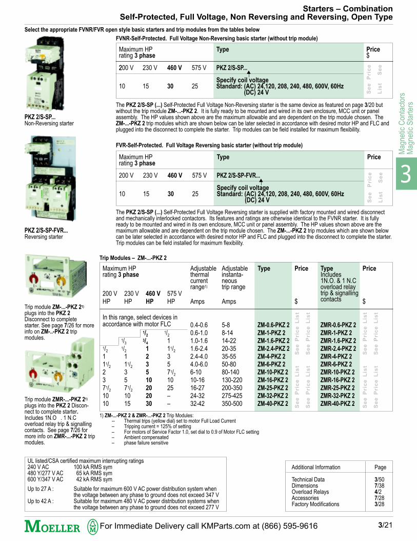
Starters – CombinationSelf-Protected, Full Voltage, Non Reversing and Reversing, Open Type
3/21
PKZ 2/S-SP...Non-Reversing starter
PKZ 2/S-SP-FVR...Reversing starter
Select the appropriate FVNR/FVR open style basic starters and trip modules from the tables below
FVNR-Self-Protected. Full Voltage Non-Reversing basic starter (without trip module)
The PKZ 2/S-SP (...) Self-Protected Full Voltage Non-Reversing starter is the same device as featured on page 3/20 butwithout the trip module ZM-...-PKZ 2. It is fully ready to be mounted and wired in its own enclosure, MCC unit or panelassembly. The HP values shown above are the maximum allowable and are dependent on the trip module chosen. TheZM-...-PKZ 2 trip modules which are shown below can be later selected in accordance with desired motor HP and FLC andplugged into the disconnect to complete the starter. Trip modules can be field installed for maximum flexibility.
FVR-Self-Protected. Full Voltage Reversing basic starter (without trip module)
The PKZ 2/S-SP (...) Self-Protected Full Voltage Reversing starter is supplied with factory mounted and wired disconnectand mechanically interlocked contactors. Its features and ratings are otherwise identical to the FVNR starter. It is fullyready to be mounted and wired in its own enclosure, MCC unit or panel assembly. The HP values shown above are themaximum allowable and are dependent on the trip module chosen. The ZM-...-PKZ 2 trip modules which are shown belowcan be later selected in accordance with desired motor HP and FLC and plugged into the disconnect to complete the starter.Trip modules can be field installed for maximum flexibility.
230 V
15
460 V
30
575 V
25
230 V
15
460 V
30
575 V
25
Trip Modules – ZM-...-PKZ 2
200 VHP
1/2
111/22371/2
1010
230 VHP
1/3
1/2
111/23571/2
1015
575 VHP
1/2
111/23571/2
1025––
460 V
HP
1/2
3/4
1
2
3
5
10
20
20
30
Adjustableinstanta-neoustrip range
Adjustablethermalcurrentrange1)
Maximum HPrating 3 phase
Type Price
Amps
0.4-0.60.6-1.01.0-1.61.6-2.42.4-4.04.0-6.06-1010-1616-2724-3232-42
Amps
5-88-1414-2220-3535-5550-8080-140130-220200-350275-425350-500
Trip module ZMR-...-PKZ 21)
plugs into the PKZ 2 Discon-nect to complete starter.Includes 1N.O . 1 N.Coverload relay trip & signallingcontacts. See page 7/26 formore info on ZMR-...-PKZ 2 tripmodules.
1) ZM-...-PKZ 2 & ZMR-...-PKZ 2 Trip Modules:-- Thermal trips (yellow dial) set to motor Full Load Current– Tripping current = 125% of setting– For motors of Service Factor 1.0, set dial to 0.9 of Motor FLC setting– Ambient compensated– phase failure sensitive
Price TypeIncludes1N.O. & 1 N.Coverload relaytrip & signallingcontacts
Se
e P
ric
e L
ist
S
ee
P
ric
e L
ist
Se
e P
ric
e L
ist
S
ee
P
ric
e L
ist
Se
e P
r ic
e L
ist
S
ee
P
r ic
e L
ist
Se
e P
r ic
e L
ist
S
ee
P
r ic
e L
ist
Price
Price$
$ $
UL listed/CSA certified maximum interrupting ratings240 V AC 100 kA RMS sym480 Y/277 V AC 65 kA RMS sym600 Y/347 V AC 42 kA RMS sym
Up to 27 A : Suitable for maximum 600 V AC power distribution system whenthe voltage between any phase to ground does not exceed 347 V
Up to 42 A : Suitable for maximum 480 V AC power distribution systems whenthe voltage between any phase to ground does not exceed 277 V
Additional Information Page
Technical Data 3/50Dimensions 7/38Overload Relays 4/2Accessories 7/28Factory Modifications 3/28
Trip module ZM-...-PKZ 21)
plugs into the PKZ 2
Disconnect to completestarter. See page 7/26 for moreinfo on ZM-..-PKZ 2 tripmodules.
For Immediate Delivery call KMParts.com at (866) 595-9616

3
Magnetic C
ontactorsM
agnetic Starters
InsulatingMaterialEnclosure
Type 12
Add suffix/I to type
Price$
DusttightenclosureIndustrial
Type 12
Add suffix/SD to type
Price$
Weather-proofenclosure
Type 3R
Add suffix/DW to type
Price$
1) UL listed short circuit withstand for DIL...M...(...)M/ starters (using DIL...M System contactors through 50 HP at 460V) is 25 kA RMS sym. at 480 V AC.
200 VHP
3–
571/2
10
–1520
25
3040
30–40
60
–75–
125
UL/CSA Maximum HPRating 50/60 Hz
3 phase
M 00M-10/ZM/Z00-...
M 00AM-10/ZM/Z00-...
M 0M/11/ZM/Z00-...
M 0AM/11/ZM6/Z..-...
M 1M/11/ZM6/Z1-40
M 2M/11/ZM6/Z1-...
M 2M/11/ZM6/Z1-57
M 2AM/11/ZM6/Z1-...
M 3M 80/11/ZM6/Z5-...
M 4M 115/11/ZM6/Z5-...
M 4M 115/11/ZM9/Z5-...
M 3-22/ZM6/Z4-...
M 4-22/ZM6/Z4-...
M 4-22/ZM9/Z4-140
M 6-22/ZM9/Z4-...
M 8-22/ZM9/Z4-...
M 8-22/ZM10/Z4-240
M 8-22/ZM10/ZW7-...
M 8A-22/ZM10/ZW7-...
460 V
HP
5
71/2
10
15
20
30
40
50
60
75
100
60
75
100
150
–
200
–
300
Enclosed
GeneralPurposeEnclosure
Type 1
Add suffix/S to type
Price$NO
11
11
1
111
1
11
222
2
222
2
Starters – CombinationBreaker Type, Full Voltage, Non Reversing
3/22
230 VHP
3–
71/2
10
–
152025
30
4050
304050
75
––100
150
StandardAuxiliaryContacts
575 VHP
––
1520
25
304050
75
100125
75100–
150
200–250
300
NC
00
11
1
111
1
11
222
2
222
2
Type1)
Insert overload relay suffixcode ... from page 3/33(Suffix has already beenprovided on certain types.)
1 2 43 5 6 7
DIL Universal Contactors
DIL...M System Contactors
See P
rice L
ist
See P
rice L
ist
S
ee P
rice L
ist
S
ee P
rice L
ist
S
ee P
rice L
ist
S
ee P
rice L
ist
See P
rice L
ist
See P
rice L
ist
S
ee P
rice L
ist
S
ee P
rice L
ist
S
ee P
rice L
ist
S
ee P
rice L
ist
See P
rice L
ist
See P
rice L
ist
S
ee P
rice L
ist
S
ee P
rice L
ist
S
ee P
rice L
ist
S
ee P
rice L
ist
See P
rice L
ist
See P
rice L
ist
S
ee P
rice L
ist
S
ee P
rice L
ist
S
ee P
rice L
ist
S
ee P
rice L
ist
See P
rice L
ist
S
ee P
rice L
ist
S
ee P
rice L
ist
S
ee P
rice L
ist
S
ee P
rice L
ist
S
ee P
rice L
ist
See P
rice L
ist
S
ee P
rice L
ist
S
ee P
rice L
ist
S
ee P
rice L
ist
S
ee P
rice L
ist
S
ee P
rice L
ist
See P
rice L
ist
See P
rice L
ist
S
ee P
rice L
ist
S
ee P
rice L
ist
S
ee P
rice L
ist
S
ee P
rice L
ist
See P
rice L
ist
See P
rice L
ist
S
ee P
rice L
ist
S
ee P
rice L
ist
S
ee P
rice L
ist
S
ee P
rice L
ist
To Order Specify: Type Number (for 10 HP @ 460 V AC)
Type Number Overload Enclosure Add Coil VoltageOverload Relay suffix Type Relay Suffix Suffix from p. 3/46-47Enclosure SuffixCoil Voltage M 0M/11/ZM/Z00- 16 /S 120 V 60 Hz
Accessories
How to Order
Additional Information Page
Technical Data 3/50Dimensions 3/61Overload Relays 4/2Accessories 3/35Factory Modifications 3/28
For Immediate Delivery call KMParts.com at (866) 595-9616

3
Mag
netic
Con
tact
ors
Mag
netic
Sta
rter
s
InsulatingMaterialEnclosure
Type 12
Add suffix/I to type
DusttightenclosureIndustrial
Type 12
Add suffix/SD to type
Weather-proof en-closure
Type 3R
Add suffix/DW to type
See P
rice L
ist
S
ee P
rice L
ist
S
ee P
rice L
ist
S
ee P
rice L
ist
S
ee P
rice L
ist
S
ee P
rice L
ist
See P
rice L
ist
S
ee P
rice L
ist
S
ee P
rice L
ist
S
ee P
rice L
ist
S
ee P
rice L
ist
S
ee P
rice L
ist
200 VHP
3–
571/2
10
–1520
25
3040
30–40
60
–75–
125
UL/CSA Maximum HPRating 50/60 Hz
3 phase
MW 00M-01/ZM/Z00-...2)
MW 00AM-01/ZM/Z00-...2)
MW 0M/11/ZM/Z00-...
MW 0AM/11/ZM6/Z...-...
MW 1M/11/ZM6/Z1-40
MW 2M/11/ZM6/Z1-...
MW 2M/11/ZM6/Z1-57
MW 2AM/11/ZM6/Z1-...
MW 3M 80/11/ZM6/Z5-...
MW 4M 115/11/ZM6/Z5-...
MW 4M 115/11/ZM9/Z5-...
MW 3-22/ZM6/Z4-...
MW 4-22/ZM6/Z4-...
MW 4-22/ZM9/Z4-140
MW 6-22/ZM9/Z4-...
MW 8-22/ZM9/Z4-...
MW 8-22/ZM10/Z4-240
MW 8-22/ZM10/ZW7-...
MW 8A-22/ZM10/ZW7-...
NO
00
11
1
111
1
11
222
2
222
2
NC
11
11
1
111
1
11
222
2
222
2
3/23
Enclosed
GeneralPurposeEnclosure
Type 1
Add suffix/S to type
1) UL listed short circuit withstand for MW...M/ starters (using DIL...M System contactors through 50 HP at 460V) is 25 kA RMS sym. at 480 V AC.2) Contactors equipped with 1 NC auxiliary contact only for electrical interlocking purposes. For additional auxiliary contacts see page 3/35.
StandardAuxiliaryContacts
Type1)
Insert overload relay suffixcode ... from page 3/33(Suffix has already beenprovided on certain types.)
1 2 3 4 5 6 7
Starters – CombinationBreaker Type, Full Voltage, Reversing
460V
HP
5
71/2
10
15
20
30
40
50
60
75
100
60
75
100
150
–
200
–
300
230 VHP
3–
71/2
10
–
152025
30
4050
304050
75
––100
150
575 VHP
––
1520
25
304050
75
100125
75100–
150
200–250
300
DIL Universal Contactors
DIL...M System Contactors
See P
rice L
ist
S
ee P
rice L
ist
S
ee P
rice L
ist
S
ee P
rice L
ist
S
ee P
rice L
ist
S
ee P
rice L
ist
See P
rice L
ist
S
ee P
rice L
ist
S
ee P
rice L
ist
S
ee P
rice L
ist
S
ee P
rice L
ist
S
ee P
rice L
ist
See P
rice L
ist
S
ee P
rice L
ist
S
ee P
rice L
ist
S
ee P
rice L
ist
S
ee P
rice L
ist
S
ee P
rice L
ist
See P
rice L
ist
S
ee P
rice L
ist
S
ee P
rice L
ist
S
ee P
rice L
ist
S
ee P
rice L
ist
S
ee P
rice L
ist
See P
rice L
ist
S
ee P
rice L
ist
S
ee P
rice L
ist
S
ee P
rice L
ist
S
ee P
rice L
ist
S
ee P
rice L
ist
See P
rice L
ist
S
ee P
rice L
ist
S
ee P
rice L
ist
S
ee P
rice L
ist
S
ee P
rice L
ist
S
ee P
rice L
ist
Price
$Price
$Price
$Price
$
Additional Information Page
Technical Data 3/50Dimensions 3/61Overload Relays 4/2Accessories 3/35Factory Modifications 3/28
How to Order
To Order Specify: Type Number (for 30 HP @ 460 V AC)
Type Number Overload Enclosure Add Coil VoltageOverload Relay suffix Type Relay Suffix Suffix from p. 3/46-47Enclosure SuffixCoil Voltage MW 2M/11/ZM6/Z1-... 57 /S 120 V 60 Hz
Accessories
For Immediate Delivery call KMParts.com at (866) 595-9616
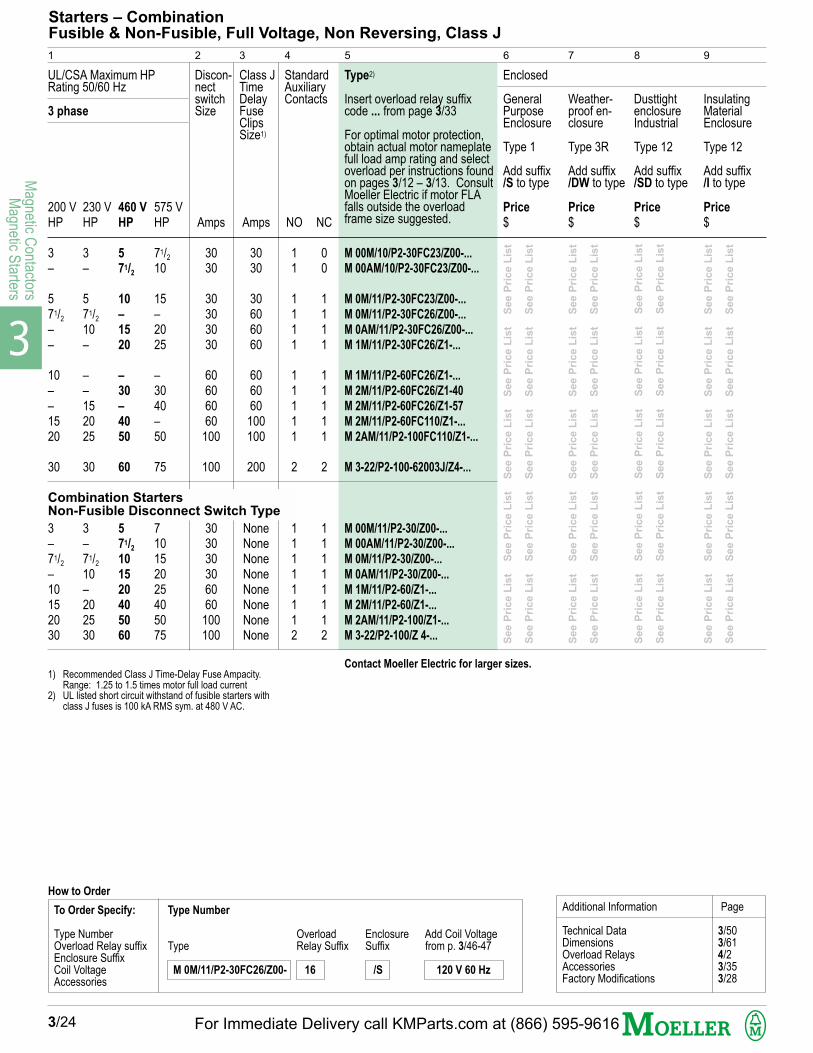
3
Magnetic C
ontactorsM
agnetic Starters
NO
11
1111
11111
2
11111112
InsulatingMaterialEnclosure
Type 12
Add suffix/I to type
DusttightenclosureIndustrial
Type 12
Add suffix/SD to type
Weather-proof en-closure
Type 3R
Add suffix/DW to type
200 VHP
3–
571/2
––
10––1520
30
3–71/2
–10152030
M 00M/10/P2-30FC23/Z00-...
M 00AM/10/P2-30FC23/Z00-...
M 0M/11/P2-30FC23/Z00-...
M 0M/11/P2-30FC26/Z00-...
M 0AM/11/P2-30FC26/Z00-...
M 1M/11/P2-30FC26/Z1-...
M 1M/11/P2-60FC26/Z1-...
M 2M/11/P2-60FC26/Z1-40
M 2M/11/P2-60FC26/Z1-57
M 2M/11/P2-60FC110/Z1-...
M 2AM/11/P2-100FC110/Z1-...
M 3-22/P2-100-62003J/Z4-...
M 00M/11/P2-30/Z00-...
M 00AM/11/P2-30/Z00-...
M 0M/11/P2-30/Z00-...
M 0AM/11/P2-30/Z00-...
M 1M/11/P2-60/Z1-...
M 2M/11/P2-60/Z1-...
M 2AM/11/P2-100/Z1-...
M 3-22/P2-100/Z 4-...
UL/CSA Maximum HPRating 50/60 Hz
3 phase
Enclosed
GeneralPurposeEnclosure
Type 1
Add suffix/S to type
Starters – CombinationFusible & Non-Fusible, Full Voltage, Non Reversing, Class J
3/24
1) Recommended Class J Time-Delay Fuse Ampacity.Range: 1.25 to 1.5 times motor full load current
2) UL listed short circuit withstand of fusible starters withclass J fuses is 100 kA RMS sym. at 480 V AC.
460 V
HP
5
71/2
10
–
15
20
–
30
–
40
50
60
5
71/2
10
15
20
40
50
60
StandardAuxiliaryContacts
575 VHP
71/2
10
15–2025
–3040–50
75
710152025405075
NC
00
1111
11111
2
11111112
Type2)
Insert overload relay suffixcode ... from page 3/33
For optimal motor protection,obtain actual motor nameplatefull load amp rating and selectoverload per instructions foundon pages 3/12 – 3/13. ConsultMoeller Electric if motor FLAfalls outside the overloadframe size suggested.
1 2 43 5 6 7
Class JTimeDelayFuseClipsSize1)
Discon-nectswitchSize
Amps
3030
30303030
60606060
100
100
303030306060
100100
Amps
3030
30606060
606060100100
200
NoneNoneNoneNoneNoneNoneNoneNone
230 VHP
3–
571/2
10–
––152025
30
3–71/2
10–202530
8 9
Contact Moeller Electric for larger sizes.
See P
rice L
ist
S
ee P
rice L
ist
S
ee P
rice L
ist
S
ee P
rice L
ist
S
ee P
rice L
ist
See P
rice L
ist
S
ee P
rice L
ist
S
ee P
rice L
ist
S
ee P
rice L
ist
S
ee P
rice L
ist
See P
rice L
ist
S
ee P
rice L
ist
S
ee P
rice L
ist
S
ee P
rice L
ist
S
ee P
rice L
ist
See P
rice L
ist
S
ee P
rice L
ist
S
ee P
rice L
ist
S
ee P
rice L
ist
S
ee P
rice L
ist
See P
rice L
ist
S
ee P
rice L
ist
S
ee P
rice L
ist
S
ee P
rice L
ist
S
ee P
rice L
ist
See P
rice L
ist
S
ee P
rice L
ist
S
ee P
rice L
ist
S
ee P
rice L
ist
S
ee P
rice L
ist
See P
rice L
ist
S
ee P
rice L
ist
S
ee P
rice L
ist
S
ee P
rice L
ist
S
ee P
rice L
ist
See P
rice L
ist
S
ee P
rice L
ist
S
ee P
rice L
ist
S
ee P
rice L
ist
S
ee P
rice L
ist
Price
$Price
$Price
$Price
$
Additional Information Page
Technical Data 3/50Dimensions 3/61Overload Relays 4/2Accessories 3/35Factory Modifications 3/28
To Order Specify: Type Number
Type Number Overload Enclosure Add Coil VoltageOverload Relay suffix Type Relay Suffix Suffix from p. 3/46-47Enclosure SuffixCoil Voltage M 0M/11/P2-30FC26/Z00- 16 /S 120 V 60 Hz
Accessories
How to Order
Combination StartersNon-Fusible Disconnect Switch Type
For Immediate Delivery call KMParts.com at (866) 595-9616
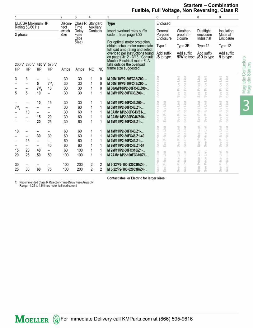
3
Mag
netic
Con
tact
ors
Mag
netic
Sta
rter
s
200 VHP
3––5
–71/2
–––
10–––1520
3025
InsulatingMaterialEnclosure
Type 12
Add suffix/I to type
DusttightenclosureIndustrial
Type 12
Add suffix/SD to type
Weather-proof en-closure
Type 3R
Add suffix/DW to type
Type
Insert overload relay suffixcode ... from page 3/33
For optimal motor protection,obtain actual motor nameplatefull load amp rating and selectoverload per instructions foundon pages 3/12 - 3/13. ConsultMoeller Electric if motor FLAfalls outside the overloadframe size suggested.
M 00M/10/P2-30FC33/Z00-...
M 00M/10/P2-30FC43/Z00-...
M 00AM/10/P2-30FC43/Z00-...
M 0M/11/P2-30FC33/Z00-...
M 0M/11/P2-30FC43/Z00-...
M 0M/11/P2-30FC43/Z1-...
M 0AM/11/P2-30FC43/Z1-...
M 0AM/11/P2-30FC46/Z00-...
M 1M/11/P2-30FC46/Z1-...
M 1M/11/P2-60FC43/Z1-...
M 2M/11/P2-60FC46/Z1-40
M 2M/11/P2-60FC43/Z1-...
M 2M/11/P2-60FC46/Z1-57
M 2M/11/P2-60FC310/Z1-...
M 2AM/11/P2-100FC310/Z1-...
M 3-22/P2-100-22003R/Z4-...
M 3-22/P2-100-62003R/Z4-...
UL/CSA Maximum HPRating 50/60 Hz
3 phase
Starters – CombinationFusible, Full Voltage, Non Reversing, Class R
Enclosed
GeneralPurposeEnclosure
Type 1
Add suffix/S to type
NO
1111
11111
111111
22
1) Recommended Class R Rejection-Time-Delay Fuse AmpacityRange: 1.25 to 1.5 times motor full load current
460 V
HP
–
5
71/2
10
10
–
–
15
20
–
30
–
–
40
50
–
60
StandardAuxiliaryContacts
575 VHP
–71/2
10–
15––2025
–30–40–50
–75
NC
0001
11111
111111
22
1 2 43 5 6 7
Class RTimeDelayFuseClipsSize1)
Discon-nectswitchSize
Amps
30303030
3030303030
6060606060100
100100
Amps
30303030
3060606060
60606060100100
200200
230 VHP
3––5
––10––
––15–2025
–30
8 9
Contact Moeller Electric for larger sizes.
See P
rice L
ist
S
ee P
rice L
ist
S
ee P
rice L
ist
S
ee P
rice L
ist
See P
rice L
ist
S
ee P
rice L
ist
S
ee P
rice L
ist
S
ee P
rice L
ist
See P
rice L
ist
S
ee P
rice L
ist
S
ee P
rice L
ist
S
ee P
rice L
ist
See P
rice L
ist
S
ee P
rice L
ist
S
ee P
rice L
ist
S
ee P
rice L
ist
See P
rice L
ist
S
ee P
rice L
ist
S
ee P
rice L
ist
S
ee P
rice L
ist
See P
rice L
ist
S
ee P
rice L
ist
S
ee P
rice L
ist
S
ee P
rice L
ist
See P
rice L
ist
S
ee P
rice L
ist
S
ee P
rice L
ist
S
ee P
rice L
ist
See P
rice L
ist
S
ee P
rice L
ist
S
ee P
rice L
ist
For Immediate Delivery call KMParts.com at (866) 595-9616
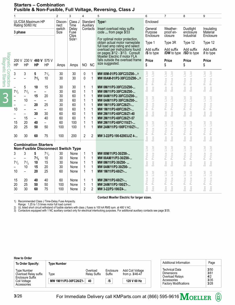
3
Magnetic C
ontactorsM
agnetic Starters
200 VHP
3–
–71/2
–––10––1520
30
3–71/2
–10
152030
InsulatingMaterialEnclosure
Type 12
Add suffix/I to type
DusttightenclosureIndustrial
Type 12
Add suffix/SD to type
Weather-proof en-closure
Type 3R
Add suffix/DW to type
MW 00M-01/P2-30FC23/Z00-...3)
MW 00AM-01/P2-30FC23/Z00-...3)
MW 0M/11/P2-30FC23/Z00-...
MW 0M/11/P2-30FC26/Z00-...
MW 0AM/11/P2-30FC23/Z00-...
MW 0AM/11/P2-30FC26/Z00-...
MW 1M/11/P2-30FC26/Z1-...
MW 1M/11/P2-60FC26/Z1-...
MW 2M/11/P2-60FC26/Z1-40
MW 2M/11/P2-60FC26/Z1-57
MW 2M/11/P2-60FC110/Z1-...
MW 2AM/11/P2-100FC110/Z1-...
MW 3-22/P2-100-62003J/Z 4-...
MW 00M/11/P2-30/Z00-...
MW 00AM/11/P2-30/Z00-...
MW 0M/11/P2-30/Z00- ...
MW 0AM/11/P2-30/Z00- ...
MW 1M/11/P2-60/Z1-...
MW 2M/11/P2-60/Z1-...
MW 2AM/11/P2-100/Z1-...
MW 3-22/P2-100/Z4-...
UL/CSA Maximum HPRating 50/60 Hz
3 phase
Enclosed
GeneralPurposeEnclosure
Type 1
Add suffix/S to type
NO
00
1111111111
2
11111
112
Starters – CombinationFusible & Non-Fusible, Full Voltage, Reversing, Class J
3/26
1) Recommended Class J Time-Delay Fuse Ampacity.Range: 1.25 to 1.5 times motor full load current
2) UL listed short circuit withstand of fusible starters with class J fuses is 100 kA RMS sym. at 480 V AC.3) Contactors equipped with 1 NC auxiliary contact only for electrical interlocking purposes. For additional auxiliary contacts see page 3/35.
StandardAuxiliaryContacts
575 VHP
71/2
10
15–20–25–3040–50
75
71/2
10152025
405075
NC
11
1111111111
2
11111
112
Type2)
Insert overload relay suffixcode ... from page 3/33
For optimal motor protection,obtain actual motor nameplatefull load amp rating and selectoverload per instructions foundon pages 3/12 - 3/13. ConsultMoeller Electric if motor FLAfalls outside the overload framesize suggested.
1 2 43 5 6 7
Class JTimeDelayFuseClipsSize1)
Discon-nectswitchSize
Amps
3030
303030303060606060
100
100
3030303060
60100100
Amps
3030
3060606060606060
100100
200
NoneNoneNoneNoneNone
NoneNoneNone
8 9
Contact Moeller Electric for larger sizes.
See P
rice L
ist
S
ee P
rice L
ist
S
ee P
rice L
ist
S
ee P
rice L
ist
S
ee P
rice L
ist
See P
rice L
ist
S
ee P
rice L
ist
S
ee P
rice L
ist
S
ee P
rice L
ist
S
ee P
rice L
ist
See P
rice L
ist
S
ee P
rice L
ist
S
ee P
rice L
ist
S
ee P
rice L
ist
S
ee P
rice L
ist
See P
rice L
ist
S
ee P
rice L
ist
S
ee P
rice L
ist
S
ee P
rice L
ist
S
ee P
rice L
ist
See P
rice L
ist
S
ee P
rice L
ist
S
ee P
rice L
ist
S
ee P
rice L
ist
S
ee P
rice L
ist
See P
rice L
ist
S
ee P
rice L
ist
S
ee P
rice L
ist
S
ee P
rice L
ist
S
ee P
rice L
ist
See P
rice L
ist
S
ee P
rice L
ist
S
ee P
rice L
ist
S
ee P
rice L
ist
S
ee P
rice L
ist
See P
rice L
ist
S
ee P
rice L
ist
S
ee P
rice L
ist
S
ee P
rice L
ist
S
ee P
rice L
ist
Price
$230 VHP
3–
571/2
–10–––152025
30
3–71/2
10–
202530
460 V
HP
5
71/2
10
–
15
–20
–
30
–40
50
60
5
71/2
10
15
20
40
50
60
Price
$Price
$Price
$
Additional Information Page
Technical Data 3/50Dimensions 3/61Overload Relays 4/2Accessories 3/35Factory Modifications 3/28
To Order Specify: Type Number
Type Number Overload Enclosure Add Coil VoltageOverload Relay suffix Type Relay Suffix Suffix from p. 3/46-47Enclosure SuffixCoil Voltage MW 1M/11/P2-30FC26/Z1- 40 /S 120 V 60 Hz
Accessories
How to Order
Combination StartersNon-Fusible Disconnect Switch Type
For Immediate Delivery call KMParts.com at (866) 595-9616

3
Mag
netic
Con
tact
ors
Mag
netic
Sta
rter
s
200 VHP
3––5
–71/2
–––
10–––1520
2530
Weather-proof en-closure
Type 3R
Add suffix/DW to type
DusttightenclosureIndustrial
Type 12
Add suffix/SD to type
InsulatingMaterialEnclosure
Type 12
Add suffix/I to type
MW 00M-01/P2-30FC33/Z00-...2)
MW 00M-01/P2-30FC43/Z00-...2)
MW 00AM-01/P2-30FC43/Z00-...2)
MW 0M/11/P2-30FC33/Z00-...
MW 0M/11/P2-30FC43/Z00-...
MW 0M/11/P2-30FC43/Z1-...
MW 0AM/11/P2-30FC43/Z1-...
MW 0AM/11/P2-30FC43/Z00-...
MW 1M/11/P2-30FC46/Z1-...
MW 1M/11/P2-60FC43/Z1-...
MW 2M/11/P2-60FC46/Z1-40
MW 2M/11/P2-60FC43/Z1-...
MW 2M/11/P2-60FC46/Z1-57
MW 2M/11/P2-60FC310/Z1-...
MW 2AM/11/P2-100FC310/Z1-...
MW 3-22/P2-100-62003R/Z4-...
MW 3-22/P2-100-22003R/Z4-...
UL/CSA Maximum HPRating 50/60 Hz
3 phase
Starters – CombinationFusible, Full Voltage, Reversing, Class R
Enclosed
GeneralPurposeEnclosure
Type 1
Add suffix/S to type
NO
0001
11111
111111
22
1) Recommended Class R Rejection-Time-Delay Fuse Ampacity.Range: 1.25 to 1.5 times motor full load current
2) Contactors equipped with 1 NC auxiliary contact only for electricalinterlocking purposes. For additional auxiliary contacts see page 3/35.
460 V
HP
–
5
71/2
–
10
–
–
15
20
–
25
–
30
40
50
60
–
StandardAuxiliaryContacts
575 VHP
–71/2
10–
15––2025
–30–40–50
75–
NC
1111
11111
111111
22
Type
Insert overload relay suffixcode ... from page 3/33
For optimal motor protection,obtain actual motor nameplatefull load amp rating and selectoverload per instructions foundon pages 3/12 - 3/13. ConsultMoeller Electric if motor FLAfalls outside the overload framesize suggested.
1 2 43 5 6 7
Class RTimeDelayFuseClipsSize1)
Discon-nectswitchSize
Amps
30303030
3030303030
6060606060100
100100
Amps
30303030
3060606060
60606060100100
200200
230 VHP
3––5
––10––
––15–2025
30–
8 9
Contact Moeller Electric for larger sizes.
See P
rice L
ist
S
ee P
rice L
ist
S
ee P
rice L
ist
S
ee P
rice L
ist
See P
rice L
ist
S
ee P
rice L
ist
S
ee P
rice L
ist
S
ee P
rice L
ist
See P
rice L
ist
S
ee P
rice L
ist
S
ee P
rice L
ist
S
ee P
rice L
ist
See P
rice L
ist
S
ee P
rice L
ist
S
ee P
rice L
ist
S
ee P
rice L
ist
See P
rice L
ist
S
ee P
rice L
ist
S
ee P
rice L
ist
S
ee P
rice L
ist
See P
rice L
ist
S
ee P
rice L
ist
S
ee P
rice L
ist
S
ee P
rice L
ist
See P
rice L
ist
S
ee P
rice L
ist
S
ee P
rice L
ist
S
ee P
rice L
ist
See P
rice L
ist
S
ee P
rice L
ist
S
ee P
rice L
ist
S
ee P
rice L
ist
Price
$Price
$Price
$Price
$
Additional Information Page
Technical Data 3/50Dimensions 3/61Overload Relays 4/2Accessories 3/35Factory Modifications 3/28
3/27
To Order Specify: Type Number
Type Number Overload Enclosure Add Coil VoltageOverload Relay suffix Type Relay Suffix Suffix from p. 3/46-47Enclosure SuffixCoil Voltage MW 0M/11/P2-30FC43/Z00- 16 /S 120 V 60 Hz
Accessories
How to Order
For Immediate Delivery call KMParts.com at (866) 595-9616

3
Magnetic C
ontactorsM
agnetic Starters
Starters – Full VoltageFactory Modifications
Ordering Information:
Order by description
The standard modifications shown on this page are those available for factory installation. Prices for these modifications are shown in the alphanumeric price bookunder “Starters - Full Voltage Factory Modifications”. The enclosure may or may not change with the addition of any of these items. When accurate dimensions ofthe enclosure are required, refer to your nearest Moeller Electric distributor or sales office.
Description
Pilot Devices in CoverEnclosure Type Price
addition allsizes$
Push Buttons
"START-STOP" or "ON-OFF"Double push button
"START-STOP" or "ON-OFF"Double push button with indicating light
Standard 1 unit push buttonStandard 2 unit push buttonStandard 3 unit push button
Selector Switches
"HAND-O-AUTO" Selector Switch"MAN-AUTO" Selector Switch
Pilot Lights
Pilot light (specify color)
Push-to-test light or illuminatedpush button
1, 12, 12K, 3R13, 3, 4, 4X
1, 12, 12K, 3R13, 3, 4, 4X
1, 12, 12K, 3R1, 12, 12K, 3R1, 12, 12K, 3R
1, 12, 12K, 3R, 4X1, 12, 12K, 3R, 4X
1, 12, 12K, 3R13, 3, 4, 4X
1, 12, 12K, 3R13, 3, 4, 4X
Description
Control Circuit
Separate control circuitFused control circuit – 250 V, 1 or 2 fusesFused control circuit – 600 V, 2 fuses
Auxiliary Relays
Control relay, maximum of 4 poles – unwired– wired
Timing relayTerminal Block wired – per pole
Auxiliary Relays for Multi-speed Starter Only
Compelling relayAccelerating relay – 2 speedTime decelerating relay – 2 speedPhase reversal and failure relay
Overload Relays
Ambient compensated, phase failure sensitive 3 Phasebimetallic O/L relay Type Z... supplied as standardP.T.C. Thermistor Tripping Unit
Name Plates
Special nameplates, 3" x 1"
Price
addition allsizes$
Description (E)EM00M00AM0M$
0AM1M1AM
$
2M2AM
$
3-224-22
$
3M 80
$
PKZ 2Self-ProtectedStarter$
8-228a-22
$
4M 1156-22
$
Control Circuit Transformers
Transformer 60 Hz with fused primary
Transformer with additional capacity up to100 V, 60 Hz with fused primary
Overload Relay
Omit overload relay – deduct
Mechanical Interlock for Contactors
Disconnect Device (for Multi-speed
Starters only)
Disconnect switch – non-fusible– fusible
Circuit Breaker
3/28
Price addition to Starter – Select using contactor frame size
Se
e
Pri
ce
L
ist
S
ee
P
ric
e
Lis
t
Se
e
Pri
ce
L
ist
S
ee
P
ric
e
Lis
t
Se
e P
r ic
e L
ist
S
ee
P
r ic
e L
ist
S
ee
P
r ic
e L
ist
Se
e P
r ic
e L
ist
S
ee
P
r ic
e L
ist
S
ee
P
r ic
e L
ist
Se
e
Pri
ce
L
ist
S
ee
P
ric
e
Lis
t
Se
e
Pr i
ce
L
ist
S
ee
P
r ic
e
Lis
t
Se
e
Pr i
ce
L
ist
S
ee
P
r ic
e
Lis
t
Se
e
Pr i
ce
L
ist
S
ee
P
r ic
e
Lis
t
Se
e
Pr i
ce
L
ist
S
ee
P
r ic
e
Lis
t
Se
e
Pr i
ce
L
ist
S
ee
P
r ic
e
Lis
t
Se
e
Pr i
ce
L
ist
S
ee
P
r ic
e
Lis
t
Se
e
Pr i
ce
L
ist
S
ee
P
r ic
e
Lis
t
Se
e
Pr i
ce
L
ist
S
ee
P
r ic
e
Lis
t
Se
e
Pri
ce
L
ist
S
ee
P
ric
e
Lis
t
Se
e
Pr i
ce
L
ist
S
ee
P
r ic
e
Lis
t
Se
e
Pr i
ce
L
ist
S
ee
P
r ic
e
Lis
t
Se
e
Pr i
ce
L
ist
S
ee
P
r ic
e
Lis
t
Se
e
Pr i
ce
L
ist
S
ee
P
r ic
e
Lis
t
Se
e P
ric
e L
ist
S
ee
P
ric
e L
ist
S
ee
P
ric
e L
ist
Se
e P
ric
e L
ist
S
ee
P
ric
e L
ist
S
ee
P
ric
e L
ist
For Immediate Delivery call KMParts.com at (866) 595-9616

3
Mag
netic
Con
tact
ors
Mag
netic
Sta
rter
s
80% 100%
80% 65%64% 42%
100%
Line voltage60%45%
Starters – Reduced VoltageGeneral
Reduced voltage starting is required when there are limitations on inrush current or when the load cannot stand the mechanical shock of starting. Starting current and starting torque
can be reduced by reducing the applied voltage to the motor stator terminals. A change in voltage applied to the stator results in a change of flux proportional to primary voltage.
Stator and rotor currents vary in proportion to applied stator voltage. Since motor torque is proportional to the product of flux and rotor current, torque is proportional to the square
of the voltage applied to the stator. The commonly used types of reduced voltage or current motor starters are Autotransformer, Star-Delta, Part Winding, Primary Resistor and
Reactor.
Comparison Chart for Reduced Voltage Starters
Autotransformer Starter
Type AT (page 3/30)
Star-Delta Starter
Type SD (page 3/31)
Part Winding Starter
Type PW1)
Primary Resistor Starter
Type PR1)
Motor Re-quirements
Can be used with anystandard squirrel cagemotor.
Requires a specialmotor with 6 leadsbrought out (Deltawound stator).
Requires a specialmotor in which the stat-or windings are dividedinto two or more equalparts with six leads pro-vided. Also dual volt-age motors can be usedon the lower range.
Can be used with anystandard squirrel cagemotor.
Reactor Starter
Type R1)
Can be used with anystandard squirrel cagemotor.
Descrip-tion ofOperation
The motor is connectedto the line through thereduced voltage taps ofan autotransformer forthe starting interval andthen directly across theline for runningcondition.
This method requirestwo main or line con-tactors to connect themotor winding in deltaconnection for running.A third contactor isused to form the starpoint on the startingstep.
Like the star-delta start-er, this starter requiresno external equipment.One winding is connect-ed to the line for start-ing. After a time intervalthe second or runcontactor connects theother motor winding tothe line in parallel withthe first winding.
A high resistance isconnected in series withthe motor on startingand after a time intervalthis resistance is short-circuited and motor isconnected directly to theline.
The motor is connectedto the line through thereduced voltage taps ofa reactor for the start-ing interval and thendirectly across the linefor running condition.
StartingCharacter-istics inpercent ofnormal:
Advan-tages
Limita-tions
High torque efficiency.All the power takenfrom the line, exceptfor transformer losses,is transmitted to themotor. The startingcurrent and torque areeasily adjusted bychanging autotrans-former taps. Closedcircuit transition.
The star-delta starterprovides low inrushcurrent with high torqueefficiency, without theuse of any externalequipment. Open circuittransition is standard butclosed transition can beachieved with the use ofresistors and anadditional contactor.
Part-winding startingprovides one-stepacceleration at areduced current. Sothat the secondcurrent inrush is notobjectionable. Closedcircuit transition.
This type providesalmost as smooth start-ing as the reactor typestarter. The currentbecomes lower and thevoltage at the motorterminals rises as themotor accelerates.Closed circuit transition.
This type provides thesmoothest starting ofall reduced voltagestarting methods. Moresuitable for jogging orinching service. Closedcircuit transition.
Torque remainspractically constant forthe first step andpractically constant atanother value for thesecond step.
Starting characteristicsdepend on motordesign and cannot beadjusted. Requiresspecial delta woundmotor.
Requires special motoror dual-voltage motoron low range. Torqueefficiency is usuallypoor for high speedmotors.
Unavoidable power lossin resistor. Low torqueefficiency. Duty cyclelimited by thermalcapacity of resistor.
Taps must be selectedon job site to obtainstarting voltage levelsuitable for the load.
Applications wherethere are limitations onstarting voltage andcurrent. Most widelyused.
Applica-tions
Low starting torqueapplications.
Commercial airconditioning equipment.
Geared or belted drives,and other delicateapplications.
Textile machinery, andother driven loadsrequiring smoothshock-less starting.
Approxi-mate PriceCompari-son (% ofType AT)
100% 60% 40% More than 100% More than 100%
Autotransformertaps at:
80- 65- 50%
Current 64 42 25%Torque 64 42 25%
100%
33%33%
Variable with tap settingand load.
Application
1) Please contact Moeller Electric for information about these items.
3/29For Immediate Delivery call KMParts.com at (866) 595-9616
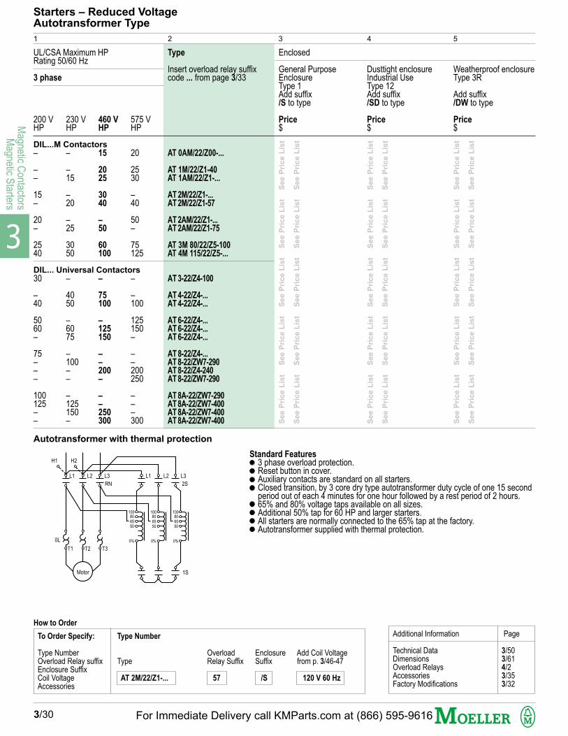
3
Magnetic C
ontactorsM
agnetic Starters
200 VHP
–
––
15–
20–
2540
30
–40
5060–
75–––
100125––
Weatherproof enclosureType 3R
Add suffix/DW to type
AT 0AM/22/Z00-...
AT 1M/22/Z1-40AT 1AM/22/Z1-...
AT 2M/22/Z1-...AT 2M/22/Z1-57
AT 2AM/22/Z1-...AT 2AM/22/Z1-75
AT 3M 80/22/Z5-100AT 4M 115/22/Z5-...
AT 3-22/Z4-100
AT 4-22/Z4-...AT 4-22/Z4-...
AT 6-22/Z4-...AT 6-22/Z4-...AT 6-22/Z4-...
AT 8-22/Z4-...AT 8-22/ZW7-290AT 8-22/Z4-240AT 8-22/ZW7-290
AT 8A-22/ZW7-290AT 8A-22/ZW7-400AT 8A-22/ZW7-400AT 8A-22/ZW7-400
UL/CSA Maximum HPRating 50/60 Hz
3 phase
230 VHP
–
–15
–20
–25
3050
–
4050
–6075
–100––
–125150–
Dusttight enclosureIndustrial UseType 12Add suffix/SD to type
Starters – Reduced VoltageAutotransformer Type
Enclosed
General PurposeEnclosureType 1Add suffix/S to type
460 VHP
15
2025
3040
–50
60100
–
75100
–125150
––200–
––250300
575 VHP
20
2530
–40
50–
75125
–
–100
125150–
––200250
–––300
Type
Insert overload relay suffixcode ... from page 3/33
1 2 43 5
3/30
DIL...M Contactors
DIL... Universal Contactors
See P
rice L
ist
S
ee P
rice L
ist
S
ee P
rice L
ist
S
ee P
rice L
ist
S
ee P
rice L
ist
See P
rice L
ist
S
ee P
rice L
ist
S
ee P
rice L
ist
S
ee P
rice L
ist
S
ee P
rice L
ist
See P
rice L
ist
S
ee P
rice L
ist
S
ee P
rice L
ist
S
ee P
rice L
ist
S
ee P
rice L
ist
See P
rice L
ist
S
ee P
rice L
ist
S
ee P
rice L
ist
S
ee P
rice L
ist
S
ee P
rice L
ist
See P
rice L
ist
S
ee P
rice L
ist
S
ee P
rice L
ist
S
ee P
rice L
ist
S
ee P
rice L
ist
See P
rice L
ist
S
ee P
rice L
ist
S
ee P
rice L
ist
S
ee P
rice L
ist
S
ee P
rice L
ist
Price$
Price$
Price$
Additional Information Page
Technical Data 3/50Dimensions 3/61Overload Relays 4/2Accessories 3/35Factory Modifications 3/32
Standard Features3 phase overload protection.Reset button in cover.Auxiliary contacts are standard on all starters.Closed transition, by 3 core dry type autotransformer duty cycle of one 15 secondperiod out of each 4 minutes for one hour followed by a rest period of 2 hours.65% and 80% voltage taps available on all sizes.Additional 50% tap for 60 HP and larger starters.All starters are normally connected to the 65% tap at the factory.Autotransformer supplied with thermal protection.
To Order Specify: Type Number
Type Number Overload Enclosure Add Coil VoltageOverload Relay suffix Type Relay Suffix Suffix from p. 3/46-47Enclosure SuffixCoil Voltage AT 2M/22/Z1-... 57 /S 120 V 60 Hz
Accessories
How to Order
H1 H2
L1 L2 L3 L1 L2 L3
RN 2S
100806550
0%
100806550
0%
100806550
0%
T1 T2 T3
0L
Motor 1S
Autotransformer with thermal protection
For Immediate Delivery call KMParts.com at (866) 595-9616

3
Mag
netic
Con
tact
ors
Mag
netic
Sta
rter
s
200 VHP
––––253040
5060100–200
Weatherproof enclosureType 3R
Add suffix/DW to type
SD 0M/22/Z00-...
SD 0AM/22/Z00-...
SD 1M/22/Z1-...
SD 1AM/22/Z1-...
SD 2M/22/Z1-...
SD 2AM/22/Z1-...
SD 3M 80/22/Z4-...
SD 3-22/Z4-...
SD 4-22/Z4-...
SD 6-22/Z4-...
SD 8-22/ZW7-...
SD 8A-22/ZW7-...
UL/CSA Maximum HPRating 50/60 Hz
3 phase
230 VHP
––1525304050
–75125150250
Dusttight enclosureIndustrial UseType 12Add suffix/SD to type
Starters – Reduced VoltageStar-Delta Open Transition Type
Enclosed
General PurposeEnclosureType 1Add suffix/S to type
460 V
HP
15
25
30
40
50
75
100
100
150
250
350
500
575 VHP
203040506075125
–150250400–
Type
Insert overload relay suffixcode ... from page 3/331)
1 2 43 5
1) Overload relays selected for setting at 58% of Motor FLC.2) For Star-Delta Closed Transition starters, please consult Moeller Electric.
3/31
See P
rice L
ist
S
ee
Pri
ce L
ist
S
ee P
rice L
ist
See P
rice L
ist
S
ee
Pri
ce L
ist
S
ee P
rice L
ist
See P
rice L
ist
S
ee P
rice L
ist
S
ee P
rice L
ist
See P
rice L
ist
S
ee P
rice L
ist
S
ee P
rice L
ist
See P
rice L
ist
S
ee P
rice L
ist
S
ee P
rice L
ist
See P
rice L
ist
S
ee P
rice L
ist
S
ee P
rice L
ist
Open Transition2)DIL...M Contactors
DIL... Universal Contactors
Price
$Price
$Price
$
Standard Features3 phase overload protection for setting at 58% of Motor FLC.Reset button in cover.Standard auxiliary contacts.
Additional Information Page
Technical Data 3/50Dimensions 3/61Overload Relays 4/2Accessories 3/35Factory Modifications 3/32
To Order Specify: Type Number
Type Number Overload Enclosure Add Coil VoltageOverload Relay suffix Type Relay Suffix Suffix from p. 3/46-47Enclosure SuffixCoil Voltage SD 1M/22/Z1-... 40 /S 120 V 60 Hz
Accessories
How to Order
H1 H2
L1 L2 L3 L1 L2 L31M 2M
T1 T2 T3 T6 T4 T5S
T6 T4 T5
T1 T2 T3
T4 T5 T6
0L
Motor
Open transition starter
For Immediate Delivery call KMParts.com at (866) 595-9616
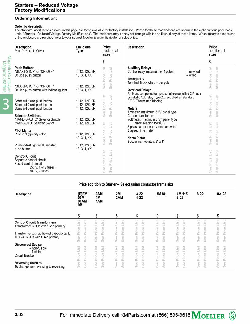
3
Magnetic C
ontactorsM
agnetic Starters
Starters – Reduced VoltageFactory Modifications
Ordering Information:
Order by description
The standard modifications shown on this page are those available for factory installation. Prices for these modifications are shown in the alphanumeric price bookunder “Starters - Reduced Voltage Factory Modifications”. The enclosure may or may not change with the addition of any of these items. When accurate dimensionsof the enclosure are required, refer to your nearest Moeller Electric distributor or sales office.
Description
Pilot Devices in CoverEnclosure
Type
Priceaddition allsizes
$
Push Buttons
"START-STOP" or "ON-OFF"Double push button
"START-STOP" or "ON-OFF"Double push button with indicating light
Standard 1 unit push buttonStandard 2 unit push buttonStandard 3 unit push button
Selector Switches
"HAND-O-AUTO" Selector Switch"MAN-AUTO" Selector Switch
Pilot Lights
Pilot light (specify color)
Push-to-test light or illuminatedpush button
Control Circuit
Separate control circuitFused control circuit
250 V, 1 or 2 fuses600 V, 2 fuses
1, 12, 12K, 3R13, 3, 4, 4X
1, 12, 12K, 3R13, 3, 4, 4X
1, 12, 12K, 3R1, 12, 12K, 3R1, 12, 12K, 3R
1, 12, 12K, 3R1, 12, 12K, 3R
1, 12, 12K, 3R13, 3, 4, 4X
1, 12, 12K, 3R13, 3, 4, 4X
Description
Auxiliary Relays
Control relay, maximum of 4 poles – unwired– wired
Timing relayTerminal Block wired – per pole
Overload Relays
Ambient compensated, phase failure sensitive 3 Phasebimetallic O/L relay Type Z... supplied as standardP.T.C. Thermistor Tripping
Meters
Ammeter, maximum 3 1/2" panel typeCurrent transformerVoltmeter, maximum 3 1/2" panel type
direct reading to 600 V3 phase ammeter or voltmeter switchElapsed time meter
Name Plates
Special nameplates, 3" x 1"
Priceaddition allsizes
$
Description (E)EM00M00AM0M
$
0AM1M1AM
$
2M2AM
$
3-224-22
$
3M 80
$
8A-22
$
8-22
$
4M 1156-22
$
Control Circuit Transformers
Transformer 60 Hz with fused primary
Transformer with additional capacity up to100 VA, 60 Hz with fused primary
Disconnect Device
– non-fusible– fusible
Circuit Breaker
Reversing Starters
To change non-reversing to reversing
3/32
Price addition to Starter – Select using contactor frame size
See P
rice L
ist
S
ee P
rice L
ist
See P
rice L
ist
S
ee P
rice L
ist
See P
rice L
ist
S
ee P
rice L
ist
See P
rice L
ist
S
ee P
rice L
ist
See P
rice L
ist
S
ee P
rice L
ist
See P
rice L
ist
S
ee P
rice L
ist
See P
rice L
ist
S
ee P
rice L
ist
See P
rice L
ist
S
ee P
rice L
ist
See P
rice L
ist
S
ee P
rice L
ist
See P
rice L
ist
S
ee P
rice L
ist
See P
rice L
ist
S
ee P
rice L
ist
See P
rice L
ist
S
ee P
rice L
ist
See P
rice L
ist
S
ee P
rice L
ist
See P
rice L
ist
S
ee P
rice L
ist
See P
rice L
ist
S
ee P
rice L
ist
See P
rice L
ist
S
ee P
rice L
ist
Se
e P
ric
e L
ist
S
ee
Pri
ce
Lis
t
Se
e P
ric
e L
ist
S
ee
Pri
ce
Lis
t
Se
e P
ric
e L
ist
S
ee
Pri
ce
Lis
t
Se
e P
ric
e L
ist
S
ee
Pri
ce
Lis
t
Se
e P
ric
e L
ist
S
ee
Pri
ce
Lis
t
Se
e P
ric
e L
ist
S
ee
Pri
ce
Lis
t
Se
e P
ric
e L
ist
S
ee
Pri
ce
Lis
t
Se
e P
ric
e L
ist
S
ee
Pri
ce
Lis
t
For Immediate Delivery call KMParts.com at (866) 595-9616
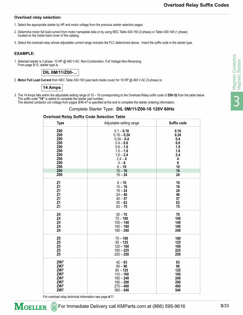
3
Mag
netic
Con
tact
ors
Mag
netic
Sta
rter
s
Overload relay selection:
1. Select the appropriate starter by HP and motor voltage from the previous starter selection pages.
2. Determine motor full load current from motor nameplate data or by using NEC Table 430-150 (3 phase) or Table 430-148 (1 phase)located on the inside back cover of this catalog.
3. Select the overload relay whose adjustable current range includes the FLC determined above. Insert the suffix code in the starter type.
EXAMPLE:
1. Selected starter is 3 phase, 10 HP @ 460 V AC, Non-Combination, Full Voltage Non-Reversing.From page 3/12, starter type is:
DIL 0M/11/Z00-...
2. Motor Full Load Current from NEC Table 430-150 (see back inside cover) for 10 HP @ 460 V AC (3 phase) is:
14 Amps
3. The 14 Amps falls within the adjustable setting range of 10 – 16 corresponding to the Overload Relay suffix code of Z00-16 from the table below.The suffix code "16" is added to complete the starter part number.The desired contactor coil voltage from pages 3/46-47 is specified at the end to complete the starter ordering information.
Overload Relay Suffix Codes
For overload relay technical information see page 4/11.
Complete Starter Type: DIL 0M/11/Z00-16 120V 60Hz
3/33
Type
Z00
Z00
Z00
Z00
Z00
Z00
Z00
Z00
Z00
Z00
Z00
Z00
Z1
Z1
Z1
Z1
Z1
Z1
Z1
Z4
Z4
Z4
Z4
Z4
Z5
Z5
Z5
Z5
Z5
ZW7
ZW7
ZW7
ZW7
ZW7
ZW7
ZW7
ZW7
Adjustable setting range
0.1 – 0.16
0.16 – 0.24
0.24 – 0.4
0.4 – 0.6
0.6 – 1.0
1.0 – 1.6
1.6 – 2.4
2.4 – 4
4 – 6
6 – 10
10 – 16
16 – 24
6 – 10
10 – 16
16 – 24
24 – 40
40 – 57
50 – 63
63 – 75
50 – 70
70 – 100
100 – 140
140 – 180
180 – 240
70 – 100
95 – 125
120 – 160
160 – 225
200 – 250
42 – 63
60 – 90
85 – 125
110 – 160
160 – 240
190 – 290
270 – 400
360 – 540
Suffix code
0.16
0.24
0.4
0.6
1.0
1.6
2.4
4
6
10
16
24
10
16
24
40
57
63
75
70
100
140
180
240
100
125
160
225
250
63
90
125
160
240
290
400
540
Overload Relay Suffix Code Selection Table
For Immediate Delivery call KMParts.com at (866) 595-9616

3
Magnetic C
ontactorsM
agnetic Starters
QDD/K11-CS
QDDL/K11/FT125/6-CSQDDL/K11/FT240/6-CSQDDL/K11/FT480/6-CS
RWK1V/K10-CSRWK1V/K11-CS
RWK3R/K20-CS
RL-RT/FT125/6-CSRL-RT/FT220/6-CSRL-RT/FT500/6-CS
T50-230-460/120-PR
T75-230-460/120-PR
T100-230-460/120-PR
T150-230-460/120-PR
T500-230-460/120-PR
2 positions
VA Rating
50
75
100
150
500
Double pushbutton mounting in singlehole
Contacts: 1 NO, 1 NC
Double pushbutton with transformertype indicating light for mounting insingle hole
V AC: Primary Secondary115-125 6220-240 6480-500 6
Two position selector switch withlegend plate. Maintained position.
Contacts: 1 NO1 NO, 1 NC
Three position selector switch withlegend plate. Maintained position.
Contacts: 2 NO
Transformer type indicating lightV AC: Primary Secondary
115-125 6220-240 6480-500 6
For use with contactor:
DIL EEM, EMDIL 00M, DIL 00AMDIL 0M, DIL 0AMDIL 1M, DIL 1AM
DIL 2M, DIL 2AM, S-PKZ2
DIL 3-22,-NA, DIL 3M 80, DIL 4-22-NADIL M 185, DIL M 225, DIL M 250
DIL 4M 115, DIL 6-22-NA, DIL M 300DIL M 400, DIL M 500
DIL 8-22-NA, DIL 8A-22-NA
Field Modification Kits
1
Double Pushbutton
Illustrations
3 positions
Indicating Light red (incandescent)
Control Transformers1)
Including primary fuse block and fuses
1) The standard enclosure may or may not have room for the addition of a control transformer. Consult Moeller Electric.Transformers are dual voltage primary: 220–240 V/440–480 V; single voltage secondary: 110–120 V. Class CC primary fusing supplied as standard.Consult Moeller Electric for secondary fusing options and fuseless primary/secondary protection alternatives.
Symbols andlegend plates
TypeFor use inenclosureswith lift-offor hinged covers
2 3
Price
Selector Switches
3/34
4 5
Description
$
Se
e P
ric
e L
ist
Se
e P
ric
e L
ist
S
ee
Pri
ce
Lis
t
Se
e P
ric
e L
ist
S
ee
Pri
ce
Lis
t
Se
e P
ric
e L
ist
S
ee
Pri
ce
Lis
t
Se
e P
ric
e L
ist
Se
e P
ric
e L
ist
S
ee
Pri
ce
Lis
t
Se
e P
ric
e L
ist
S
ee
Pri
ce
Lis
t
Se
e P
ric
e L
ist
S
ee
Pri
ce
Lis
t
13
14
21
22
13
14
0 21
22
13
14
0 23
24
0
X1 X2
For Immediate Delivery call KMParts.com at (866) 595-9616

3
Mag
netic
Con
tact
ors
Mag
netic
Sta
rter
s
Contactor Frame Size DIL EEM, EM. The followingauxiliary contact combinations are possible:
Contactor Frame Size DIL 00M...2AM. The followingauxiliary contact combinations are possible:
11 DIL M02 DIL20 DIL22 DIL M31 DIL M22 DDIL M04 DIL13 DIL40 DIL31 DIL22 DIL
11 DIL M
02 DIL
20 DIL
11 DIL EM
02 DIL EM
02 DIL E
20 DIL E
11 DDIL E2)
11 DIL E
22 DIL M
31 DIL M
22 DDIL M2)
04 DIL
13 DIL
40 DIL
31 DIL
22 DIL
22 DIL EM
04 DIL E
13 DIL E
22 DIL E
31 DIL E
40 DIL E
22 DDIL E2)
Type
DIL 00AMDIL 00M(4)DIL 0(A)MDIL 1(A)MDIL 2(A)M
Contactors – Accessories
1
Auxiliary Contacts – Top Mounted1)
2-Pole
4-Pole
Number ofContactsNO =Normally OpenNC =Normally Closed
For use with Contactorframe size
RemarksPrice
DIL 00AMDIL 00M(4)DIL 0(A)MDIL 1(A)MDIL 2(A)M
DIL (E)EM-10(-G)DIL EM4(-G)
DIL (E)EM-01(-G)DIL (E)EM-10(-G)DIL EM4(-G)
DIL 00AMDIL 00M(4)DIL 0(A)MDIL 1(A)MDIL 2(A)M
DIL (E)EM-10(-G)DIL EM4(-G)
DIL (E)EM-01(-G)DIL (E)EM-10(-G)DIL EM4(-G)
NC
1
2
0
1
2
2
0
1
1
2
1
2
4
3
0
1
2
2
4
3
2
1
0
2
NO
1
0
2
1
0
0
2
1
1
2
3
2
0
1
4
3
2
2
0
1
2
3
4
2
3/35
2 3 4 5 6
1) Refer to next page for side-mounted auxiliary contact combinations2) Includes one early-make and one late-break contact pair
$
DIL (E)EM-10(-G)
DIL EM4(-G)
DIL (E)EM-01(-G)
DIL (E)EM-10(-G)
DIL EM4(-G)
02 DIL E
11 DIL E
20 DIL E
11 DDIL E
04 DIL E
13 DIL E
22 DIL E
40 DIL E
22 DDIL E
+
22 DIL EM
02 DIL EM
11 DIL EM +
+
See P
rice L
ist
S
ee P
rice L
ist
S
ee P
rice L
ist
S
ee P
rice L
ist
S
ee P
rice L
ist
S
ee P
rice L
ist
S
ee P
rice L
ist
S
ee P
rice L
ist
S
ee P
rice L
ist
See P
rice L
ist
S
ee P
rice L
ist
S
ee P
rice L
ist
S
ee P
rice L
ist
S
ee P
rice L
ist
S
ee P
rice L
ist
S
ee P
rice L
ist
S
ee P
rice L
ist
S
ee P
rice L
ist
For Immediate Delivery call KMParts.com at (866) 595-9616

3
Magnetic C
ontactorsM
agnetic Starters
NO
1
0
1
1
1
1
Ratings:(A)Continu-ouscurrent
Power Pole open/enclosed
Type
4
3/36
Contactors – Accessories
1 2
Maximum 1 additional pole only.Mounts on left or right side.
See following page for auxiliary contactconversion information. Maximum number ofNO contacts:
DIL 3 – DIL 6 = 3 NODIL 8 – DIL 8A = 7 NO
1 Pole
1 Pole
Auxiliary Contacts forUniversal Contactors
DIL 3-22 through DIL 8A-22 contactorsare supplied with 4 auxiliary contacts(2 NO & 2 NC). Each single pole auxiliarycontact can be exchanged for another orits function can be modified by turning itthrough 180˚. See right and conversioninformation on following page for furtherinformation.
Number ofContactsNO =Normally OpenNC =Normally Closed
NC
0
1
1
1
1
1
35/30
55/44
75/60
NotesFor usewithContactorframesize
3 5 6
Early Make
1) Late-break contact2) Includes one early-make and one late break contact pair.
Price
$
Auxiliary Contacts-Side Mounted
DIL 0(A)MDIL 1(A)MDIL 2(A)M
DIL 0MthroughDIL M 500
DIL 3M 80throughDIL M 500
DIL 0M
DIL 1M
DIL 2M
DIL 3-22DIL 4-22DIL 6-22DIL 8(A)-22
10 S DIL M
01 S DIL M
11 S DIL M
DIL M 820-XHI 11-SI
DIL M 820-XHI 11V-SI2)
DIL M 820-XHI 11-SA
N DIL 0M
N DIL 1M
N DIL 2M
HSI-1
HSII-1
HSIII-1
HSI-2
HSII-2
HSIII-2
N DIL ...M
+ + DIL M
DIL M 820 XHI 11-SA
DIL M 820 XHI...(V)-SI
++
DIL 3M 80 through M 500:Maximum of 8 contacts possible,2 blocks on each side.DIL M 820-XHI 11(V)-SI contactblocks can only be mounted on theinside directly to the contactor. (reference diagram above)DIL M 820-XHI 11-SA contact blocks can only be mounted on theoutside to the DIL M 820...SI contact blocks. (reference diagram above)Auxiliary contact blocks can not be mounted between a mechanicalinterlock and the contactor.
L4 7
T4 8
Se
e P
ric
e L
ist
S
ee
Pri
ce
Lis
t
Se
e P
ric
e L
ist
S
ee
Pri
ce
Lis
t
Se
e P
ric
e L
ist
S
ee
Pri
ce
Lis
t
Se
e P
ric
e L
ist
S
ee
Pri
ce
Lis
t
Se
e P
ric
e L
ist
Se
e P
ric
e L
ist
S
ee
Pri
ce
Lis
t
Se
e P
ric
e L
ist
S
ee
Pri
ce
Lis
t
Se
e P
ric
e L
ist
S
ee
Pri
ce
Lis
t
Se
e P
ric
e L
ist
S
ee
Pri
ce
Lis
t
Se
e P
ric
e L
ist
2
1
3
4
HS...
DIL M 820-XHI 11-SIDIL M 820-XHI 11V-SIDIL M 820-XHI 11-SA
01 S DIL M10 S DIL M11 S DIL M
Standard Turnedthrough 180˚
EM = Early MakeLB = Late Break
21
31
31
13
43
43
22
32
32
14
44
44
23
33
33
11
41
41
24
34
34
12
42
42
LB EM
EM LB
Maximum: 4 side -mounted contacts, 1 block oneach side for DIL 0(A)M...2(A)M contactors.Maximum of 5 contacts possible when combinedwith top-mounted contacts....S DIL M contacts cannot be combined with DIL M 820... contacts.
DIL 0(A)M through 2(A)M:Maximum of 4 contacts possible, 1 DIL M 820-XHI 11(V)-SI block oneach side. The DIL M 820... contact blocks can not be used inconjuction with the DIL 0(A)M-G contactor.
For Immediate Delivery call KMParts.com at (866) 595-9616

3
Mag
netic
Con
tact
ors
Mag
netic
Sta
rter
s
Auxiliary contact combinationsfor system DIL M contactorsDIL 0M through DIL 2AM.
Auxiliary contact modules forside and top mounting can becombined for up to a maximumof 5 auxiliary contacts.
The diagram at right shows thepossible contact configurationswhich can be realized by combiningside and top-mounted auxiliarycontact modules.
Contactorwith noauxiliary
contacts
x
x
x
x
x
x
x
x
x
x
x
x
3/37
Contactors – Accessories
Fo
r to
p m
ou
nti
ng
Conversion of auxiliary contactsfor Universal Contactors
DIL 3-22 throughDIL 8A-22
DIL 0(A)M(-G) to DIL 2(A)M(-G)
11 DILM
22 DIL M
22 DDIL M
31 DIL M
02 DIL
11 DIL
20 DIL
04 DIL
13 DIL
22 DIL
40 DIL
31 DIL
For side mounting
x = Possible – = Not possible
–
Type of auxiliary contactcircuit diagram
Auxiliary contact
NO NCPosition
Standard
as abovebut HS III-1 turnedthrough 180˚
as abovebut HS III-1 turnedthrough 180˚
as abovebut HS 1-2 and HS III-2
turned through 180˚
HS III-1 and HS III-2
replaced byHSII-1 and HS II-2
(see page 3/36)as abovebut HS II-1 turnedthrough 180˚
as abovebut HS II-2 turnedthrough 180˚
as abovebut HS II-2 andHS II-2 turnedthrough 180˚
1 2 3 4
2
3
1
–
2
3
1
–
2
1
3
4
2
1
3
4
10 S DIL M01 S DIL M
2 x 10 S DIL M2 x 01 S DIL M
11 S DIL M 2 x 11 S DIL M
x
x
x
x
x
x
x
x
x
x
x
x
x
x
x
–
–
–
x
x
x
–
–
–
–
–
x
x
–
–
–
x
x
x
–
–
–
–
–
x
–
–
–
–
–
–
–
–
–
–
–
–
–
On contactors DIL 3 to DIL 8A, asingle-pole auxiliary contact can beexchanged for another single-poleauxiliary contact (see above) or itsfunction can be modified by turningit through 180˚. By turning, the NOauxiliary contact becomes NC andNC becomes NO, 4 NO contacts notpermissible for DIL 3 – DIL 6.
Up to 4 additional auxiliary contactscan be mounted on DIL 8 and DIL 8A.Maximum of 7 NO contacts.Permissible auxiliary contacts com-bination, either 2 X standard or 2 Xsame "sond (form...)"
EM = Early MakeLB = Late Break
2
1
3
4
HS I-2 HS I-1 HS III-1 HS III-2
HS I-2 HS I-1 HS III-1 HS III-2
HS I-2 HS I-1 HS III-1 HS III-2
HS I-2 HS I-1 HS III-1 HS III-2
HS I-2 HS I-1 HS II-1 HS II-2
HS I-2 HS I-1 HS II-1 HS II-2
HS I-2 HS I-1 HS II-1 HS II-2
HS I-2 HS I-1 HS II-1 HS II-2
13
14
21
22
31
32
43
44
13
14
21
22
33
34
43
44
13
14
21
22
31
32
41
42
11
12
21
22
31
32
41
42
13
14
21
22
31
32
43
44
13
14
21
22
33
34
43
44
13
14
21
22
31
32
41
42
11
12
21
22
31
32
41
42
LB EM
EM EM
LB LB
LB LB
21
22
13
14
21
22
13
14
31
32
43
44
21
22
13
14
35
36
LB
47
48
EM
21
22
13
14
43
44
33
34
51
52
61
62
61
62
53
54
63
64
53
54
51
52
61
62
71
72
81
82
61
62
71
72
81
82
53
54
61
62
71
72
53
54
83
84
63
64
53
54
83
84
73
74
61
62
53
54
83
84
73
74
21
22
13
14
13
14
43
44
31
32
21
22
21
22
13
14
31
32
43
44
21
22
13
14
For Immediate Delivery call KMParts.com at (866) 595-9616

3
Magnetic C
ontactorsM
agnetic Starters
RC DIL E 48
RC DIL E 250
RCB DIL 48
RCB DIL 250
RCB DIL 415
RCS DIL 48
RCS DIL 250
RCS DIL 415
VG DIL E 48
VG DIL E 250
VG DIL E 415
VGB DIL 24
VGB DIL 48
VGB DIL 250
VGB DIL 415
VGC DIL 24
VGC DIL 48
VGC DIL 250
VGC DIL 415
FD B DIL
For AC operated devices.
Drop out delay should betaken into consideration
For use with AC operated devices. The DCoperated devices have built-in surge suppressorsas standard. (DIL (E)EM-...-G)
For use with AC 50/60 Hz operated devices(DIL 00M through DIL 4M 115) and DC operateddevices (DIL 00M-G through DIL 2AM-G).
DC operated devices DIL 3M 80 and 4M 115 havevaristor surge suppressors built-in.
For use with AC and DC operated contactors(DIL 00(A)M....2(A)M).
For DC operated devices.Drop out delay should be taken into consideration.
EEM, EM
00(A)M0(A)M1(A)M2(A)M
3M 804M 115
EEM, EM
00(A)M0(A)M1(A)M2(A)M3M 804M 115
00(A)M0(A)M1(A)M2(A)M
00(A)M0(A)M1(A)M2(A)M
For use with Type Price Remarks
3 4 5 6
24 – 48 V
110 – 250 V
24 – 48 V
110 – 250 V
380 – 415 V
24 – 48 V
110 – 250 V
380 – 415 V
24 – 48 V
110 – 250 V
380 – 415 V
12 – 24 V
24 – 48 V
110 – 250 V
380 – 415 V
12 – 24 V
24 – 48 V
110 – 250 V
380 – 415 V
12-250V DC
$
3/38
Varistor suppressors A1
A2
Contactors and Starters – Accessories
1
Suppressors
RC suppressors
Se
e P
ric
e L
ist
S
ee
Pri
ce
Lis
t
Se
e P
ric
e L
ist
S
ee
Pri
ce
Lis
t
Se
e P
ric
e L
ist
S
ee
Pri
ce
Lis
t
Se
e P
ric
e L
ist
S
ee
Pri
ce
Lis
t
Se
e P
ric
e L
ist
Se
e P
ric
e L
ist
S
ee
Pri
ce
Lis
t
Se
e P
ric
e L
ist
S
ee
Pri
ce
Lis
t
Se
e P
ric
e L
ist
S
ee
Pri
ce
Lis
t
Se
e P
ric
e L
ist
S
ee
Pri
ce
Lis
t
Se
e P
ric
e L
istA1
A2
2
Free-wheel diode suppressor
A1
A2
For Immediate Delivery call KMParts.com at (866) 595-9616

3
Mag
netic
Con
tact
ors
Mag
netic
Sta
rter
s
S 1 DIL 00M
S 1 DIL 0M
S 1 DIL 1M
S 1 DIL 2M
S 1 DIL 3M
S 1 DIL 4M
DIL M 400-XS1
DIL M 500-XS1
P 1 DIL EM
P 1 DIL 00M
P 1 DIL 0M
P 1 DIL 1M
P 1 DIL 2M
P 1 DIL 3M
P 1 DIL 4M
DIL M 185-XP1
Contactors and Starters – Accessories
1
For use withtype
Type Price Remarks
3 4 5 6
Finger-safe design
With type DIL M 400-XS1, a DIL M 400-XHBcover is included for protection against accidentalcontact.
With type DIL M 500-XS1, a DIL M 500-XHBcover is included for protection against accidentalcontact.
Finger safe design.Increases the open continuous current (ACI) valueof the contactor by a factor of 2.5.P 1 DIL EM and P 1 DIL 00M are 4 pole units.2 per set. The 4th pole can be broken off.
A DIL M 400-XHB cover is included for protectionagainst accidental contact.
00(A)M
0(A)M
1(A)M
2(A)M
3M 80
4M 115
M 185, M 225, M 250M 300, M 400
M 500
EEM, EM
00(A)M
0(A)M
1(A)M
2(A)M
3M 80
4M 115
M 185
4-pole
3-pole
Star-point Bridges
Paralleling Bridges
For main contacts
3/39
$
See P
rice L
ist
S
ee P
rice L
ist
S
ee P
rice L
ist
S
ee P
rice L
ist
S
ee P
rice L
ist
S
ee P
rice L
ist
S
ee P
rice L
ist
See P
rice L
ist
S
ee P
rice L
ist
S
ee P
rice L
ist
S
ee P
rice L
ist
S
ee P
rice L
ist
S
ee P
rice L
ist
S
ee P
rice L
ist
2
For Immediate Delivery call KMParts.com at (866) 595-9616
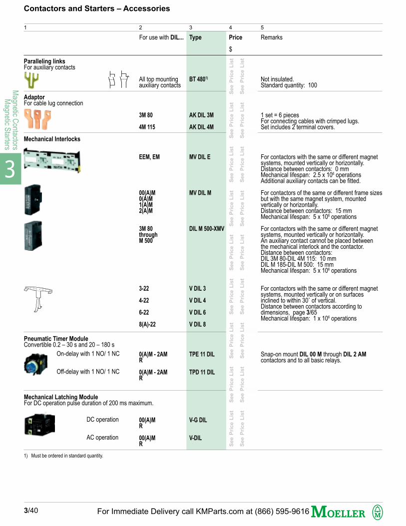
3
Magnetic C
ontactorsM
agnetic Starters
BT 4801)
AK DIL 3M
AK DIL 4M
MV DIL E
MV DIL M
DIL M 500-XMV
V DIL 3
V DIL 4
V DIL 6
V DIL 8
TPE 11 DIL
TPD 11 DIL
V-G DIL
V-DIL
3/40
Contactors and Starters – Accessories
1
For use with DIL... Type Price Remarks
2 3 4 5
Not insulated.Standard quantity: 100
1 set = 6 piecesFor connecting cables with crimped lugs.Set includes 2 terminal covers.
For contactors with the same or different magnetsystems, mounted vertically or horizontally.Distance between contactors: 0 mmMechanical lifespan: 2.5 x 10⁶ operationsAdditional auxiliary contacts can be fitted.
For contactors of the same or different frame sizesbut with the same magnet system, mountedvertically or horizontally.Distance between contactors: 15 mmMechanical lifespan: 5 x 10⁶ operations
For contactors with the same or different magnetsystems, mounted vertically or horizontally.An auxiliary contact cannot be placed betweenthe mechanical interlock and the contactor.Distance between contactors:DIL 3M 80-DIL 4M 115: 10 mmDIL M 185-DIL M 500: 15 mmMechanical lifespan: 5 x 10⁶ operations
For contactors with the same or different magnetsystems, mounted vertically or on surfacesinclined to within 30˚ of vertical.Distance between contactors according todimensions, page 3/65Mechanical lifespan: 1 x 10⁶ operations
Snap-on mount DIL 00 M through DIL 2 AMcontactors and to all basic relays.
Paralleling linksFor auxiliary contacts
All top mountingauxiliary contacts
3M 80
4M 115
EEM, EM
00(A)M0(A)M1(A)M2(A)M
3M 80throughM 500
3-22
4-22
6-22
8(A)-22
0(A)M - 2AMR
0(A)M - 2AMR
00(A)MR
00(A)MR
Mechanical Interlocks
1) Must be ordered in standard quantity.
$
AdaptorFor cable lug connection
Pneumatic Timer ModuleConvertible 0.2 – 30 s and 20 – 180 s
On-delay with 1 NO/ 1 NC
Off-delay with 1 NO/ 1 NC
DC operation
AC operation
Mechanical Latching ModuleFor DC operation pulse duration of 200 ms maximum.
See P
rice L
ist
S
ee P
rice L
ist
S
ee P
rice L
ist
S
ee P
rice L
ist
S
ee P
rice L
ist
S
ee P
rice L
ist
S
ee P
rice L
ist
S
ee P
rice L
ist
S
ee P
rice L
ist
See P
rice L
ist
S
ee P
rice L
ist
S
ee P
rice L
ist
S
ee P
rice L
ist
S
ee P
rice L
ist
S
ee P
rice L
ist
S
ee P
rice L
ist
S
ee P
rice L
ist
S
ee P
rice L
ist
For Immediate Delivery call KMParts.com at (866) 595-9616
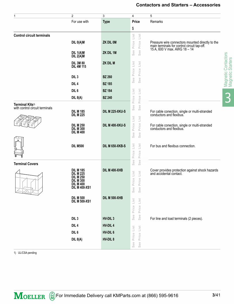
3
Mag
netic
Con
tact
ors
Mag
netic
Sta
rter
s
ZK DIL 0M
ZK DIL 1M
ZK DIL M
BZ 260
BZ 185
BZ 184
BZ 240
DIL M 225-XKU-S
DIL M 400-XKU-S
DIL M 650-XKB-S
DIL M 400-XHB
DIL M 500-XHB
HV-DIL 3
HV-DIL 4
HV-DIL 6
HV-DIL 8
Contactors and Starters – Accessories
3/41
1
For use with Type Price Remarks
2 3 4 5
Pressure wire connectors mounted directly to themain terminals for control circuit tap-off.15 A, 600 V max. AWG 18 – 14
For cable conection, single or multi-strandedconductors and flexibus.
For cable conection, single or multi-strandedconductors and flexibus.
For bus and flexibus connection.
Cover provides protection against shock hazardsand accidental contact.
For line and load terminals (2 pieces).
Control circuit terminals
DIL 0(A)M
DIL 1(A)MDIL 2(A)M
DIL 3M 80DIL 4M 115
DIL 3
DIL 4
DIL 6
DIL 8(A)
DIL M 185DIL M 225
DIL M 250DIL M 300DIL M 400
DIL M500
DIL M 185DIL M 225DIL M 250DIL M 300DIL M 400DIL M 400-XS1
DIL M 500DIL M 500-XS1
DIL 3
DIL 4
DIL 6
DIL 8(A)
Terminal Kits1)
with control circuit terminals
Terminal Covers
$
Se
e P
ric
e L
ist
S
ee
Pri
ce
Lis
t
Se
e P
ric
e L
ist
S
ee
Pri
ce
Lis
t
Se
e P
ric
e L
ist
S
ee
Pri
ce
Lis
t
Se
e P
ric
e L
ist
S
ee
Pri
ce
Lis
t
Se
e P
ric
e L
ist
S
ee
Pri
ce
Lis
t
Se
e P
ric
e L
ist
S
ee
Pri
ce
Lis
t
Se
e P
ric
e L
ist
S
ee
Pri
ce
Lis
t
Se
e P
ric
e L
ist
S
ee
Pri
ce
Lis
t
1) UL/CSA pending
For Immediate Delivery call KMParts.com at (866) 595-9616
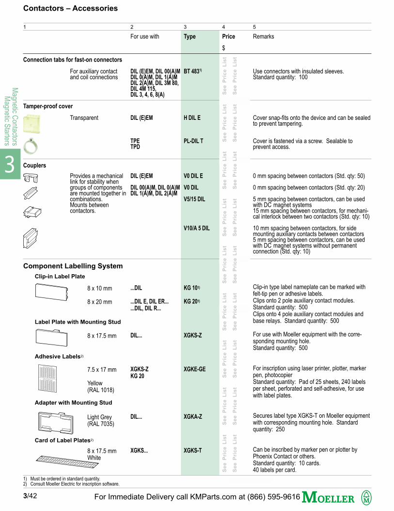
3
Magnetic C
ontactorsM
agnetic Starters
Component Labelling System
Use connectors with insulated sleeves.Standard quantity: 100
Cover snap-fits onto the device and can be sealedto prevent tampering.
Cover is fastened via a screw. Sealable toprevent access.
0 mm spacing between contactors (Std. qty: 50)
0 mm spacing between contactors (Std. qty: 20)
5 mm spacing between contactors, can be usedwith DC magnet systems15 mm spacing between contactors, for mechani-cal interlock between two contactors (Std. qty: 10)
10 mm spacing between contactors, for sidemounting auxiliary contacts between contactors5 mm spacing between contactors, can be usedwith DC magnet systems without permanentconnection (Std. qty: 10)
Clip-in type label nameplate can be marked withfelt-tip pen or adhesive labels.Clips onto 2 pole auxiliary contact modules.Standard quantity: 500Clips onto 4 pole auxiliary contact modules andbase relays. Standard quantity: 500
For use with Moeller equipment with the corre-sponding mounting hole.Standard quantity: 500
For inscription using laser printer, plotter, markerpen, photocopierStandard quantity: Pad of 25 sheets, 240 labelsper sheet, perforated and self-adhesive, for usewith label plates.
Secures label type XGKS-T on Moeller equipmentwith corresponding mounting hole. Standardquantity: 250
Can be inscribed by marker pen or plotter byPhoenix Contact or others.Standard quantity: 10 cards.40 labels per card.
Clip-in Label Plate
Label Plate with Mounting Stud
Adhesive Labels2)
Adapter with Mounting Stud
Card of Label Plates2)
For auxiliary contactand coil connections
Transparent
Provides a mechanicallink for stability whengroups of componentsare mounted together incombinations.Mounts betweencontactors.
BT 4831)
H DIL E
PL-DIL T
V0 DIL E
V0 DIL
V5/15 DIL
V10/A 5 DIL
KG 101)
KG 201)
XGKS-Z
XGKE-GE
XGKA-Z
XGKS-T
Contactors – Accessories
1
Connection tabs for fast-on connectors
For use with Type Price Remarks
2 3 4 5
DIL (E)EM, DIL 00(A)MDIL 0(A)M, DIL 1(A)MDIL 2(A)M, DIL 3M 80,DIL 4M 115,DIL 3, 4, 6, 8(A)
DIL (E)EM
TPETPD
DIL (E)EM
DIL 00(A)M, DIL 0(A)MDIL 1(A)M, DIL 2(A)M
...DIL
...DIL E, DIL ER...
...DIL, DIL R...
DIL...
XGKS-Z
KG 20
DIL...
XGKS...
Tamper-proof cover
Couplers
1) Must be ordered in standard quantity.2) Consult Moeller Electric for inscription software.
3/42
$
Se
e P
r ic
e L
ist
S
ee
Pr i
ce
Lis
t
Se
e P
r ic
e L
ist
S
ee
Pr i
ce
Lis
t
Se
e P
r ic
e L
ist
S
ee
Pr i
ce
Lis
t
Se
e P
r ic
e L
ist
S
ee
Pr i
ce
Lis
t
Se
e P
r ic
e L
ist
Se
e P
r ic
e L
ist
S
ee
Pr i
ce
Lis
t
Se
e P
r ic
e L
ist
S
ee
Pr i
ce
Lis
t
Se
e P
r ic
e L
ist
S
ee
Pr i
ce
Lis
t
Se
e P
r ic
e L
ist
S
ee
Pr i
ce
Lis
t
Se
e P
r ic
e L
ist
8 x 10 mm
8 x 20 mm
8 x 17.5 mm
7.5 x 17 mm
Yellow(RAL 1018)
Light Grey(RAL 7035)
8 x 17.5 mmWhite
For Immediate Delivery call KMParts.com at (866) 595-9616
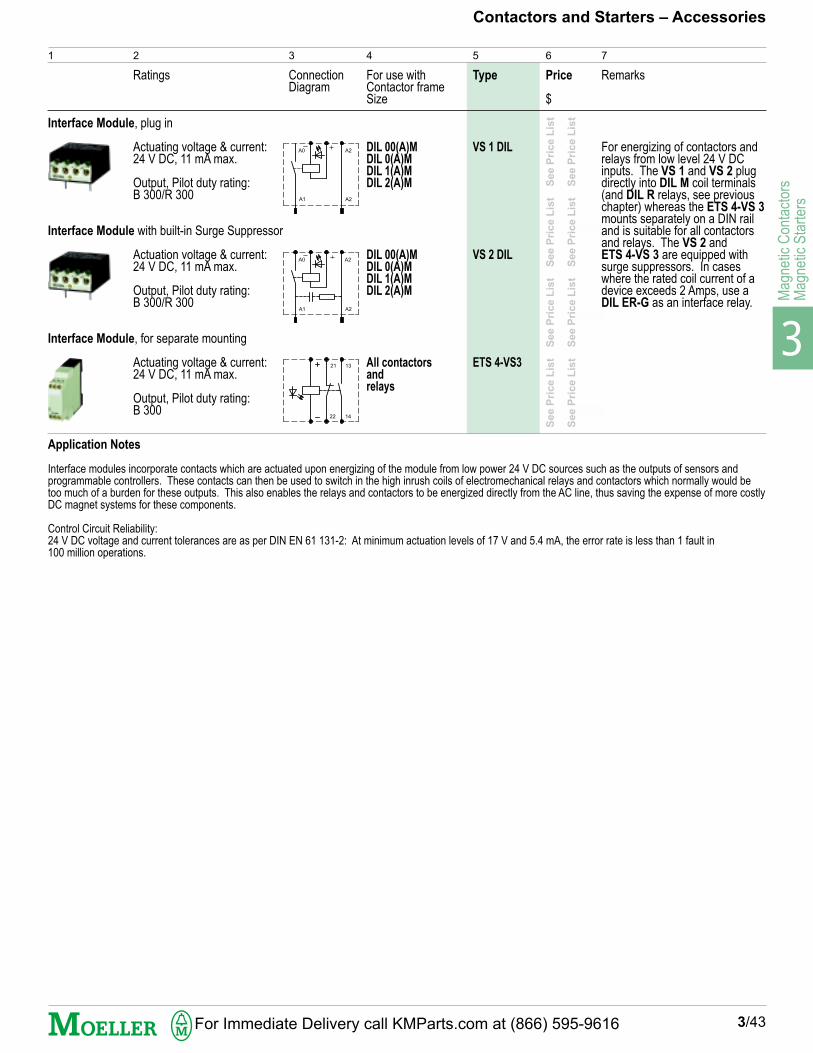
3
Mag
netic
Con
tact
ors
Mag
netic
Sta
rter
s
Type Remarks
Interface Module, plug in
Interface Module with built-in Surge Suppressor
Interface Module, for separate mounting
Ratings For use withContactor frameSize
Price
3/43
1 2
Contactors and Starters – Accessories
Actuating voltage & current:24 V DC, 11 mA max.
Output, Pilot duty rating:B 300/R 300
Actuation voltage & current:24 V DC, 11 mA max.
Output, Pilot duty rating:B 300/R 300
Actuating voltage & current:24 V DC, 11 mA max.
Output, Pilot duty rating:B 300
4 5 6 7
Application Notes
Interface modules incorporate contacts which are actuated upon energizing of the module from low power 24 V DC sources such as the outputs of sensors andprogrammable controllers. These contacts can then be used to switch in the high inrush coils of electromechanical relays and contactors which normally would betoo much of a burden for these outputs. This also enables the relays and contactors to be energized directly from the AC line, thus saving the expense of more costlyDC magnet systems for these components.
Control Circuit Reliability:24 V DC voltage and current tolerances are as per DIN EN 61 131-2: At minimum actuation levels of 17 V and 5.4 mA, the error rate is less than 1 fault in100 million operations.
See P
rice L
ist
S
ee P
rice L
ist
S
ee P
rice L
ist
S
ee P
rice L
ist
See P
rice L
ist
S
ee P
rice L
ist
S
ee P
rice L
ist
S
ee P
rice L
ist
$
DIL 00(A)MDIL 0(A)MDIL 1(A)MDIL 2(A)M
DIL 00(A)MDIL 0(A)MDIL 1(A)MDIL 2(A)M
All contactorsandrelays
VS 1 DIL
VS 2 DIL
ETS 4-VS3
For energizing of contactors andrelays from low level 24 V DCinputs. The VS 1 and VS 2 plugdirectly into DIL M coil terminals(and DIL R relays, see previouschapter) whereas the ETS 4-VS 3mounts separately on a DIN railand is suitable for all contactorsand relays. The VS 2 andETS 4-VS 3 are equipped withsurge suppressors. In caseswhere the rated coil current of adevice exceeds 2 Amps, use aDIL ER-G as an interface relay.
3
ConnectionDiagram
A0
A1
A2
A2
A0
A1
A2
A2
13
14
21
22
For Immediate Delivery call KMParts.com at (866) 595-9616


3
Mag
netic
Con
tact
ors
Mag
netic
Sta
rter
s
J-DIL 00M (...)
J-DIL 0M (...)
J-DIL 1M (...)
J-DIL 2M (...)
J-DIL 3M (...)
J-DIL 4M (...)
J-S-PKZ 2 (...)
DILM250-XSP/E (...)
DILM500-XSP/E (...)
J-DIL 3 (...)
J-DIL 4 (...)
J-DIL 6 (...)
J-DIL 8 (...)
J-DIL 8A (...)
G-DIL 00M (...)
G-DIL 0M (...)
G-DIL 1M (...)
G-DIL 2M (...)
G-DIL 3M (...)
G-DIL 4M (...)
DILM250-XSP/E (...)
DILM500-XSP/E (...)
G-DIL 3 (...)
G-DIL 4 (...)
G-DIL 6 (...)
G-DIL 8 (...)
G-DIL 8 (...)
00(A)M
0(A)M
1(A)M
2(A)M
3M 80
4M 115
PKZ 2
M 185M 225M 250
M 300M 400M 500
3
4
6
8
8A
Contactors – Replacement Coils
3/45
1
1) Coils G-DIL 3M and G-DIL 4M are protected against overvoltages by means of varistor suppressors as standard.
For use withContactor DIL...
AC TypeInsert coil voltage (...)and frequency. Seepages 3/46-47
2 3 5 6
PriceStandard Coil
$
4
PriceNon-StandardCoil$
DC Type1)
Insert coil voltage (...).See pages 3/46-47
8
PriceStandard Coil
$
7
PriceNon-StandardCoil$
See P
rice L
ist
S
ee P
rice L
ist
S
ee P
rice L
ist
S
ee P
rice L
ist
S
ee P
rice L
ist
S
ee P
rice L
ist
See P
rice L
ist
S
ee P
rice L
ist
S
ee P
rice L
ist
S
ee P
rice L
ist
S
ee P
rice L
ist
S
ee P
rice L
ist
See P
rice L
ist
S
ee P
rice L
ist
S
ee P
rice L
ist
S
ee P
rice L
ist
S
ee P
rice L
ist
S
ee P
rice L
ist
See P
rice L
ist
S
ee P
rice L
ist
S
ee P
rice L
ist
S
ee P
rice L
ist
S
ee P
rice L
ist
S
ee P
rice L
ist
See P
rice L
ist
S
ee P
rice L
ist
S
ee P
rice L
ist
S
ee P
rice L
ist
S
ee P
rice L
ist
S
ee P
rice L
ist
See P
rice L
ist
S
ee P
rice L
ist
S
ee P
rice L
ist
S
ee P
rice L
ist
S
ee P
rice L
ist
S
ee P
rice L
ist
See P
rice L
ist
S
ee P
rice L
ist
S
ee P
rice L
ist
S
ee P
rice L
ist
S
ee P
rice L
ist
S
ee P
rice L
ist
See P
rice L
ist
S
ee P
rice L
ist
S
ee P
rice L
ist
S
ee P
rice L
ist
S
ee P
rice L
ist
S
ee P
rice L
ist
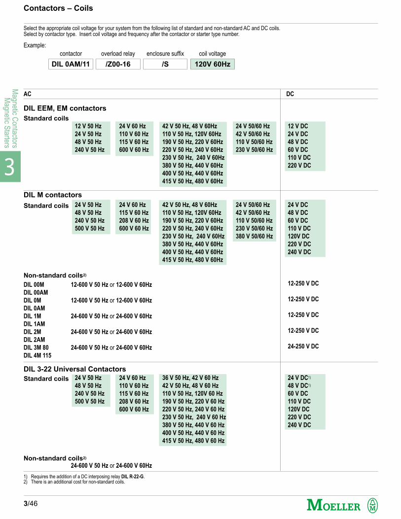
3
Magnetic C
ontactorsM
agnetic Starters
DIL 00M 12-600 V 50 Hz or 12-600 V 60Hz
DIL 00AM
DIL 0M 12-600 V 50 Hz or 12-600 V 60Hz
DIL 0AM
DIL 1M 24-600 V 50 Hz or 24-600 V 60Hz
DIL 1AM
DIL 2M 24-600 V 50 Hz or 24-600 V 60Hz
DIL 2AM
DIL 3M 80 24-600 V 50 Hz or 24-600 V 60Hz
DIL 4M 115
24-600 V 50 Hz or 24-600 V 60Hz
Select the appropriate coil voltage for your system from the following list of standard and non-standard AC and DC coils.Select by contactor type. Insert coil voltage and frequency after the contactor or starter type number.
24 V 50/60 Hz
42 V 50/60 Hz
110 V 50/60 Hz
230 V 50/60 Hz
24 V 50/60 Hz
42 V 50/60 Hz
110 V 50/60 Hz
230 V 50/60 Hz
380 V 50/60 Hz
42 V 50 Hz, 48 V 60Hz
110 V 50 Hz, 120V 60Hz
190 V 50 Hz, 220 V 60Hz
220 V 50 Hz, 240 V 60Hz
230 V 50 Hz, 240 V 60Hz
380 V 50 Hz, 440 V 60Hz
400 V 50 Hz, 440 V 60Hz
415 V 50 Hz, 480 V 60Hz
42 V 50 Hz, 48 V 60Hz
110 V 50 Hz, 120V 60Hz
190 V 50 Hz, 220 V 60Hz
220 V 50 Hz, 240 V 60Hz
230 V 50 Hz, 240 V 60Hz
380 V 50 Hz, 440 V 60Hz
400 V 50 Hz, 440 V 60Hz
415 V 50 Hz, 480 V 60Hz
36 V 50 Hz, 42 V 60 Hz
42 V 50 Hz, 48 V 60 Hz
110 V 50 Hz, 120V 60 Hz
190 V 50 Hz, 220 V 60 Hz
220 V 50 Hz, 240 V 60 Hz
230 V 50 Hz, 240 V 60 Hz
380 V 50 Hz, 440 V 60 Hz
400 V 50 Hz, 440 V 60 Hz
415 V 50 Hz, 480 V 60 Hz
3/46
Contactors – Coils
Example:
AC DC
DIL EEM, EM contactors
Standard coils
DIL M contactors
Standard coils
Non-standard coils2)
DIL 3-22 Universal Contactors
Standard coils
Non-standard coils2)
1) Requires the addition of a DC interposing relay DIL R-22-G.2) There is an additional cost for non-standard coils.
DIL 0AM/11 /Z00-16 /S 120V 60Hz
contactor overload relay enclosure suffix coil voltage
12 V 50 Hz
24 V 50 Hz
48 V 50 Hz
240 V 50 Hz
24 V 50 Hz
48 V 50 Hz
240 V 50 Hz
500 V 50 Hz
24 V 50 Hz
48 V 50 Hz
240 V 50 Hz
500 V 50 Hz
24 V 60 Hz
110 V 60 Hz
115 V 60 Hz
600 V 60 Hz
24 V 60 Hz
115 V 60 Hz
208 V 60 Hz
600 V 60 Hz
24 V 60 Hz
110 V 60 Hz
115 V 60 Hz
208 V 60 Hz
600 V 60 Hz
12 V DC
24 V DC
48 V DC
60 V DC
110 V DC
220 V DC
24 V DC
48 V DC
60 V DC
110 V DC
120V DC
220 V DC
240 V DC
12-250 V DC
12-250 V DC
12-250 V DC
12-250 V DC
24-250 V DC
24 V DC1)
48 V DC1)
60 V DC
110 V DC
120V DC
220 V DC
240 V DC
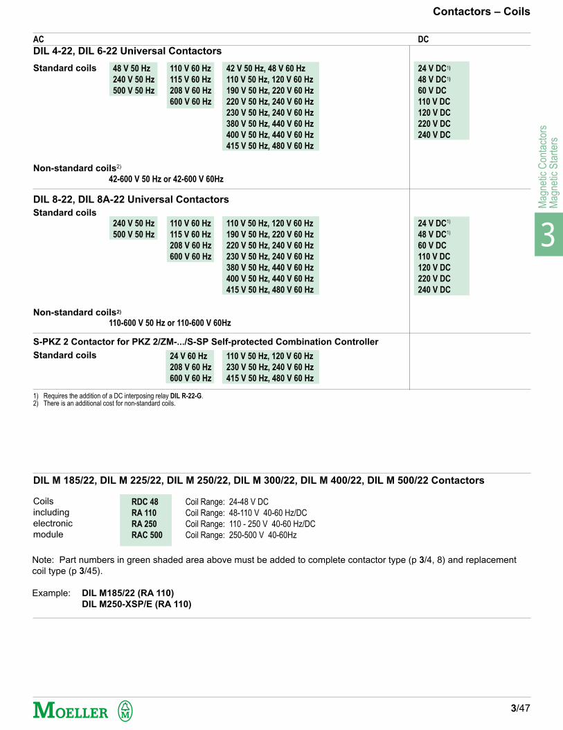
3
Mag
netic
Con
tact
ors
Mag
netic
Sta
rter
s
48 V 50 Hz
240 V 50 Hz
500 V 50 Hz
42-600 V 50 Hz or 42-600 V 60Hz
240 V 50 Hz
500 V 50 Hz
110-600 V 50 Hz or 110-600 V 60Hz
110 V 60 Hz
115 V 60 Hz
208 V 60 Hz
600 V 60 Hz
110 V 60 Hz
115 V 60 Hz
208 V 60 Hz
600 V 60 Hz
24 V 60 Hz
208 V 60 Hz
600 V 60 Hz
24 V DC1)
48 V DC1)
60 V DC
110 V DC
120 V DC
220 V DC
240 V DC
24 V DC1)
48 V DC1)
60 V DC
110 V DC
120 V DC
220 V DC
240 V DC
RDC 48 Coil Range: 24-48 V DC
RA 110 Coil Range: 48-110 V 40-60 Hz/DC
RA 250 Coil Range: 110 - 250 V 40-60 Hz/DC
RAC 500 Coil Range: 250-500 V 40-60Hz
42 V 50 Hz, 48 V 60 Hz
110 V 50 Hz, 120 V 60 Hz
190 V 50 Hz, 220 V 60 Hz
220 V 50 Hz, 240 V 60 Hz
230 V 50 Hz, 240 V 60 Hz
380 V 50 Hz, 440 V 60 Hz
400 V 50 Hz, 440 V 60 Hz
415 V 50 Hz, 480 V 60 Hz
110 V 50 Hz, 120 V 60 Hz
190 V 50 Hz, 220 V 60 Hz
220 V 50 Hz, 240 V 60 Hz
230 V 50 Hz, 240 V 60 Hz
380 V 50 Hz, 440 V 60 Hz
400 V 50 Hz, 440 V 60 Hz
415 V 50 Hz, 480 V 60 Hz
110 V 50 Hz, 120 V 60 Hz
230 V 50 Hz, 240 V 60 Hz
415 V 50 Hz, 480 V 60 Hz
Standard coils
Contactors – Coils
AC DC
DIL 4-22, DIL 6-22 Universal Contactors
DIL 8-22, DIL 8A-22 Universal Contactors
3/47
Non-standard coils2)
Standard coils
Non-standard coils2)
S-PKZ 2 Contactor for PKZ 2/ZM-.../S-SP Self-protected Combination Controller
Standard coils
DIL M 185/22, DIL M 225/22, DIL M 250/22, DIL M 300/22, DIL M 400/22, DIL M 500/22 Contactors
Coils
including
electronic
module
1) Requires the addition of a DC interposing relay DIL R-22-G.2) There is an additional cost for non-standard coils.
Note: Part numbers in green shaded area above must be added to complete contactor type (p 3/4, 8) and replacement
coil type (p 3/45).
Example: DIL M185/22 (RA 110)
DIL M250-XSP/E (RA 110)

3
Magnetic C
ontactorsM
agnetic Starters
Contactors – Selection Guide
By far the most common application of contactors is the control of electric motors. As a prime mover, the 3 phase AC motor, in particular the squirrelcage motor, dominates the field, and most of them are controlled by contactors. Contactors are expected to start, stop, reverse, plug, jog andsequence motors and, in conjunction with overload relays, to protect motors in the event of overloads.The load rating stated in HP is the basic data required to enable the correct selection of contactors to be made, but this figure by itself is not alwayssufficient. The type of load, its operating cycle, switching frequency and total life required, all influence the overall stress on contactors.The electrical durability tests of contactors, outlined in Appendix B of IEC 60 947-4, are used by manufacturers to establish contactor ratings whichincorporate a sufficient and verifiable switching capability to cover a broad range of applications as defined in the IEC Utilization categories (e.g. AC-3, AC-4). The IEC 60 947 standard states that, with respect to its resistance to electrical wear, a contactor or starter is by convention characterizedby the number of ON-LOAD operating cycles corresponding to the different utilization categories which can be made without repair or replacement.The IEC Utilization categories AC-3 and AC-4 are most often encountered in contactor applications and are outlined below. See Section 13 foradditional details.The curves at right provide a reliable guide for selection based on the electrical life desired.
Normal switching duty AC-3
for squirrel-cage motors
Compressors Lifts MixersPumps Escalators AgitatorsFans Conveyors CentrifugesValves Bucket elevators Air conditioning systems
Drives in general in manufacturing and processing machines
Make: up to 6 x rated motor currentBreak: 1 x rated motor current100% AC-3
Extreme switching duty AC-4
for squirrel-cage motors
3/48
Contactors
Printing pressesWire drawing machinesCentrifugesSpecial drives formanufacturing and processing machines
Make: 6 x rated motor currentBreak: 6 x rated motor current100% AC-4
Determination of the maximum number of operations per hour in relation to rating and utilizationcategoryPn = Maximum motor rating (kW/HP) of the contactor per pages 3/4 & 3/8 Ops/h = Maximum number of operations per hour
Type
DIL E(E)M
DIL 00(A)M(-G)
DIL 0(A)M(-G)
DIL 1(A)M(-G)
DIL 2(A)M(-G)
AC 1
2
2
2
2
2
AC 3
1
1
1
1
1
AC 4
3
3
3
3
3
Type
DIL 3M80
DIL 4M115
DIL M 185
DIL M 225
DIL M 250
DIL M 300
DIL M 400
DIL M 500
AC 1
1
1
1
1
1
2
2
2
AC 3
1
1
2
2
2
3
3
3
AC 4
4
4
5
5
5
6
6
6
Operating characteristic: Starting: From rest
Stopping: After attaining full running speed
Typical applications:
Electrical characteristics:
Utilization category:
Operating characteristic: Switching, plugging, reversing
Ops/h 9000
6000
5000
4000
3000
2000
1500
1000
800
600
500
400
300
200
150
100
0 10 20 30 40 50 60 70 80 90 100 %
[kW]N
1
2
3
Ops/h 9000
6000
5000
4000
3000
2000
600700
500
400
300
200
150
100
0 10 20 30 40 50 60 70 80 90 100 %
1
2
3
4
5
1500
1000
800
6
[kW]PN
Typical applications:
Electrical characteristics:
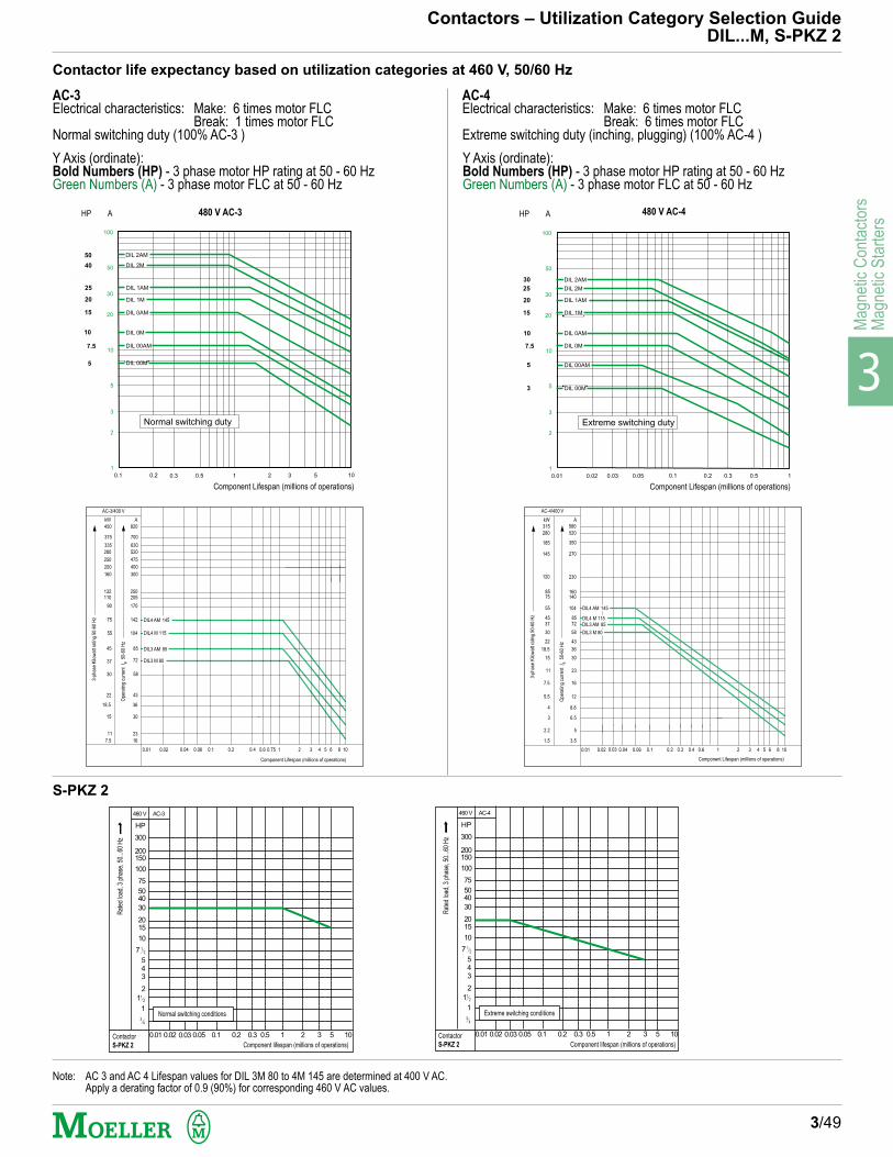
3
Mag
netic
Con
tact
ors
Mag
netic
Sta
rter
s
AC-4Electrical characteristics: Make: 6 times motor FLC
Break: 6 times motor FLCExtreme switching duty (inching, plugging) (100% AC-4 )
Contactor life expectancy based on utilization categories at 460 V, 50/60 Hz
Contactors – Utilization Category Selection GuideDIL...M, S-PKZ 2
3/49
AC-3Electrical characteristics: Make: 6 times motor FLC
Break: 1 times motor FLCNormal switching duty (100% AC-3 )
DIL 1M
DIL 0AM
DIL 0M
0.020.01 0.03 0.05 0.1 0.2 0.3 0.5 1
1
2
3
5
10
20
30
50
100
Extreme switching duty
3
5
7.5
10
15
20
25
30
DIL 00M
DIL 2AM
DIL 00AM
DIL 2M
DIL 1AM
480 V AC-4
DIL 2M
DIL 1AM
DIL 1M
DIL 0M
0.20.1 0.3 0.5 1 2 3 5 10
1
2
3
5
10
20
30
50
100
Normal switching duty
5
7.5
15
20
25
40
50
DIL 00M
DIL 00AM
10
DIL 2AM
DIL 0AM
Y Axis (ordinate):Bold Numbers (HP) - 3 phase motor HP rating at 50 - 60 HzGreen Numbers (A) - 3 phase motor FLC at 50 - 60 Hz
480 V AC-3
460 V AC-3
HP
300
200
150
100
75
50
40
30
20
15
10
7 1
2
5
4
3
2
1
11
2
3
4
Contactor
S-PKZ 2
Normal switching conditions
0.01 0.02 0.03 0.05 0.1 0.2 0.3 0.5 1 2 3 5 10
Ra
ted
lo
ad
, 3
ph
ase
, 5
0..
.60
Hz
Component lifespan (millions of operations)
460 V AC-4
HP
300
200
150
100
75
50
40
30
20
15
10
7 1
2
5
4
3
2
1
11
2
3
4
Contactor
S-PKZ 2
Extreme switching conditions
0.01 0.02 0.03 0.05 0.1 0.2 0.3 0.5 1 2 3 5 10
Ra
ted
lo
ad
, 3
ph
ase
, 5
0...6
0 H
z
Component lifespan (millions of operations)
S-PKZ 2
HP A HP A
Component Lifespan (millions of operations) Component Lifespan (millions of operations)
Y Axis (ordinate):Bold Numbers (HP) - 3 phase motor HP rating at 50 - 60 HzGreen Numbers (A) - 3 phase motor FLC at 50 - 60 Hz
Note: AC 3 and AC 4 Lifespan values for DIL 3M 80 to 4M 145 are determined at 400 V AC.Apply a derating factor of 0.9 (90%) for corresponding 460 V AC values.
DIL3 AM 85
AC-3/400 V
kW
450
375
335
280
250
200
160
132110
90
75
55
45
37
30
22
18.5
15
11
7.5
A
820
700
630
520
475
400
300
250205
170
142
104
85
72
58
43
36
30
23
16
DIL4 AM 145
DIL4 M 115
DIL3 M 80
0.01 0.02 0.04 0.06 0.1 0.2 0.4 0.6 0.75 1 2 3 4 5 6 8 10
3-ph
ase
Kilo
wat
t rat
ing
50-6
0 H
z
Component Lifespan (millions of operations)
Ope
ratin
g cu
rren
t I e 5
0-60
Hz
AC-4/400 V
kW A
0.01 0.02 0.04 0.06 0.1 0.2 0.4 0.6 1 2 3 4 5 6 8 10
315
280
185
145
120
8575
55
4537
30
22
18.5
15
0.03 0.3
11
7.5
5.5
4
3
2.2
1.5
580
520
350
270
230
160140
104
8572
58
43
36
30
23
16
12
8.8
6.5
5
3.5
DIL4 AM 145
DIL4 M 115DIL3 AM 85
DIL3 M 80
Component Lifespan (millions of operations)
3-ph
ase
Kilo
wat
t rat
ing
50-6
0 H
z
Ope
ratin
g cu
rren
t I e 5
0-60
Hz

3
Magnetic C
ontactorsM
agnetic Starters
Specifications
Mechanical life spanAC operated x 106 operationsDC operated x 106 operations
Max. operating frequency, mechanicalAC operated ops/hDC operated ops/h
Max. operating frequency electrical
Climatic Proofing
Ambient temperature Open max./min. CºEnclosed max./min. Cº
Impact resistance of make (break) contacts g
Dimensions
Main contactsRated coil voltage V AC / V DC
Rated making capacity (IEC/EN 60 947) A
Rated breaking capacityIEC/EN 60 947 220/230 V A
380/400 V A500 V A660/690 V A
Contactor life span Operations
AC-1 duty
Rated thermal current lth = Rated operating current le50/60 Hzthree-pole Open A
Enclosed Asingle-pole Open A
Enclosed A(three/four current paths in parallel)
AC-3 duty
Rated operating current le (Open and enclosed)50/60 Hz 220/230 V A
380/400 V A500 V A660/690 V A
AC-4 duty
Rated operating current le (Open and enclosed)50/60 Hz 220/230 V A
380/400 V A500 V A660/690 V A
Magnet systemPick-up valuesAC operated (dual voltage coils)50 Hz, 60 Hz Pick-up x V coil
DC operated1) Pick-up x V coil
Power consumption of the coilAC operated (dual voltage coils)50 Hz, 60 Hz Pick-up VA/W
Sealed VA/WDC operated1) Pick-up W
Sealed W
Duty factor DF %
Switching times at 100% rated coil voltage (guide only)Main contacts AC operated Closing delay ms
Opening delay msArcing time ms
Contactors – System DIL MTechnical Data
3/50
EEM EM 00M 00AM 0M 0AM
1) True DC voltage or derived from a full wave 3-phase bridge rectifier of filtered 1-phase AC supply.
General
^
UL, CSA, IEC/EN 60 947, CE, DIN VDE 0660
10 10 10 10 10 1020 20 10 10 10 10
9000 9000 7000 7000 9000 90009000 9000 9000 9000 9000 5000
see diagram on Page 3/49
Damp heat, constant to, IEC/EN 60 068-2-3Damp heat, cyclic, to IEC/EN 60 068-2-30
+50/-25 +50/-25 +50/-25 +50/-25 +50/-25 +50/-25+40/-25 +40/-25 +40/-25 +40/-25 +40/-25 +40/-25
10(8) 10(8) 10 10 8 8
Page 3/61
600/250 600/250 600/250 600/250 600/250 600/250
110 110 200 200 270 270
90 90 130 130 230 23090 90 120 120 230 23064 64 120 120 230 23054 54 100 100 210 210
See pages 3/48 – 49
20 20 20 20 35 3516 16 16 16 30 3050 50/60 50 50 85 8540 40/50 40 40 75 75
6.6 8.8 8.8 12 15.5 22.56.6 8.8 8.8 12 15.5 22.55 6.4 9 12 17 22.53.5 4.8 6.7 9 13 17.5
5 6.6 6.6 8.7 11.5 15.55 6.6 6.6 8.5 11.5 15.53.7 5 6.4 9 11.5 172.9 3.4 4.9 6.7 9 13
0.8 - 1.1 0.8-1.1 0.8-1.1 0.8-1.1 0.8-1.1 0.8-1.1
– – 0.85 - 1.1 0.85-1.1 0.85-1.1 0.85-1.1
25/22 25/22 67/52 67/52 100/72 100/724.6/1.3 4.6/1.3 8.6/2.5 8.6/2.5 10/3 10/32.6 2.6 9.5 9.5 10 102.6 2.6 9.5 9.5 10 10
100 100 100 100 100 100
14-21 14-21 14-22 14-22 9-19 9-198-18 8-18 5-14 5-14 5-13 5-1312 12 ≤ 10 ≤ 10 < 20 < 20
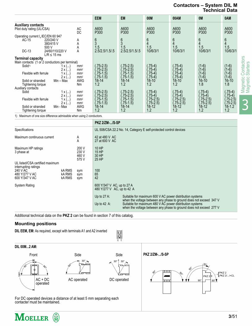
3
Mag
netic
Con
tact
ors
Mag
netic
Sta
rter
s
Specifications
Maximum continuous current AA
Maximum HP ratings 200 V3 phase at 230 V
460 V575 V
UL listed/CSA certified maximuminterrupting ratings240 V AC kA RMS sym480 Y/277 V AC kA RMS sym600 Y/347 V AC kA RMS sym
System Rating
UL 508/CSA 22.2 No. 14, Category E self-protected control devices
42 at 480 V AC27 at 600 V AC
10 HP15 HP30 HP25 HP
1006542
600 Y/347 V AC, up to 27 A480 Y/277 V AC, up to 42 A
Up to 27 A: Suitable for maximum 600 V AC power distribution systemswhen the voltage between any phase to ground does not exceed 347 V
Up to 42 A: Suitable for maximum 480 V AC power distribution systemswhen the voltage between any phase to ground does not exceed 277 V
3/51
PKZ 2/ZM-.../S-SP
For DC operated devices a distance of at least 5 mm separating eachcontacter must be maintained.
DIL 00M...2 AM:
Mounting positions
Additional technical data on the PKZ 2 can be found in section 7 of this catalog.
A600 A600 A600 A600 A600 A600P300 P300 P300 P300 P300 P300
6 6 6 6 6 63 3 4 4 4 41.5 1.5 1.5 1.5 1.5 1.52.5/2.5/1.5/.5 2.5/2.5/1.5/.5 10/6/3/1 10/6/3/1 10/6/3/1 10/6/3/1
(.75-2.5) (.75-2.5) (.75-4) (.75-4) (1-6) (1-6)(.75-2.5) (.75-2.5) (.75-4) (.75-4) (1-6) (1-6)(.75-1.5) (.75-1.5) (.75-4) (.75-4) (1-6) (1-6)(.75-1.5) (.75-1.5) (.75-4) (.75-4) (1-6) (1-6)18-14 18-14 18-10 18-10 16-10 16-101.2 1.2 1.2 1.2 1.8 1.8
(.75-2.5) (.75-2.5) (.75-4) (.75-4) (.75-4) (.75-4)(.75-2.5) (.75-2.5) (.75-4) (.75-4) (.75-4) (.75-4)(.75-1.5) (.75-1.5) (.75-2.5) (.75-2.5) (.75-2.5) (.75-2.5)(.75-1.5) (.75-1.5) (.75-2.5) (.75-2.5) (.75-2.5) (.75-2.5)18-14 18-14 18-12 18-12 18-12 18-1.21.2 1.2 1.2 1.2 1.2 1.2
Contactors – System DIL MTechnical Data
Auxiliary contactsPilot duty rating (UL/CSA) AC
DCOperating current le IEC/EN 60 947
AC-15 220/240 V A380/415 V A500 V A
DC-13 24/60/110/220 V AL/R ≤ 15 ms
Terminal capacityMain contacts (1 or 2 conductors per terminal)
Solid1) 1 x (...) mm2
2 x (...) mm2
Flexible with ferrule 1 x (...) mm2
2 x (...) mm2
Solid or stranded Min – Max AWGTightening torque Nm
Auxiliary contactsSolid 1 x (...) mm2
2 x (...) mm2
Flexible with ferrule 1 x (...) mm2
2 x (...) mm2
Solid or stranded Min - Max AWGTightening torque Nm
EEM EM 00M 00AM 0M 0AM
PKZ 2/ZM-.../S-SP
DIL EEM, EM: As required, except with terminals A1 and A2 inverted
A2
A1
Side
AC operated
90°
30°
Side
DC operated
30°30°
180°
90° 9
0°
Front
AC + DCoperated
90°
90° 90°
90°
90°
30°
PKZ 2
PKZ 2/.../+CLPKZ 2
1) Maximum of one size difference admissible when using 2 conductors.
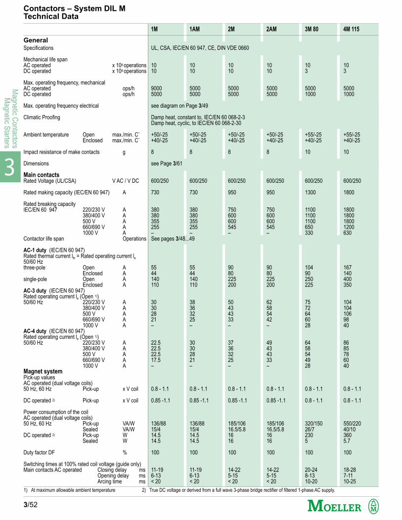
3
Magnetic C
ontactorsM
agnetic Starters
Specifications
Mechanical life spanAC operated x 106 operationsDC operated x 106 operations
Max. operating frequency, mechanicalAC operated ops/hDC operated ops/h
Max. operating frequency electrical
Climatic Proofing
Ambient temperature Open max./min. C˚Enclosed max./min. C˚
Impact resistance of make contacts g
Dimensions
Main contactsRated Voltage (UL/CSA) V AC / V DC
Rated making capacity (IEC/EN 60 947) A
Rated breaking capacityIEC/EN 60 947 220/230 V A
380/400 V A500 V A660/690 V A1000 V A
Contactor life span Operations
AC-1 duty (IEC/EN 60 947)Rated thermal current lth = Rated operating current le50/60 Hzthree-pole Open A
Enclosed Asingle-pole Open A
Enclosed AAC-3 duty (IEC/EN 60 947)Rated operating current le (Open 1))50/60 Hz 220/230 V A
380/400 V A500 V A660/690 V A1000 V A
AC-4 duty (IEC/EN 60 947)Rated operating current le (Open 1))50/60 Hz 220/230 V A
380/400 V A500 V A660/690 V A1000 V A
Magnet systemPick-up valuesAC operated (dual voltage coils)50 Hz, 60 Hz Pick-up x V coil
DC operated 2) Pick-up x V coil
Power consumption of the coilAC operated (dual voltage coils)50 Hz, 60 Hz Pick-up VA/W
Sealed VA/WDC operated 2) Pick-up W
Sealed W
Duty factor DF %
Switching times at 100% rated coil voltage (guide only)Main contacts AC operated Closing delay ms
Opening delay msArcing time ms
Contactors – System DIL MTechnical Data
3/52
1M 1AM 2M 2AM 3M 80 4M 115
GeneralUL, CSA, IEC/EN 60 947, CE, DIN VDE 0660
10 10 10 10 10 1010 10 10 10 3 3
9000 5000 5000 5000 5000 50005000 5000 5000 5000 1000 1000
see diagram on Page 3/49
Damp heat, constant to, IEC/EN 60 068-2-3Damp heat, cyclic, to IEC/EN 60 068-2-30
+50/-25 +50/-25 +50/-25 +50/-25 +55/-25 +55/-25+40/-25 +40/-25 +40/-25 +40/-25 +40/-25 +40/-25
8 8 8 8 10 10
see Page 3/61
600/250 600/250 600/250 600/250 600/250 600/250
730 730 950 950 1300 1800
380 380 750 750 1100 1800380 380 600 600 1100 1800355 355 600 600 1100 1800255 255 545 545 650 1200– – – – 330 630See pages 3/48...49
55 55 90 90 104 16744 44 80 80 90 140140 140 225 225 250 400110 110 200 200 225 350
30 38 50 62 75 10430 36 43 58 72 10428 32 43 54 64 10621 25 33 42 60 98– – – – 28 40
22.5 30 37 49 64 8622.5 30 36 43 58 8522.5 28 32 43 54 7817.5 21 25 33 49 60– – – – 28 40
0.8 - 1.1 0.8 - 1.1 0.8 - 1.1 0.8 - 1.1 0.8 - 1.1 0.8 - 1.1
0.85 -1.1 0.85 -1.1 0.85 -1.1 0.85 -1.1 0.8 - 1.1 0.8 - 1.1
136/88 136/88 185/106 185/106 320/150 550/22015/4 15/4 16.5/5.8 16.5/5.8 26/7 40/1014.5 14.5 16 16 230 36014.5 14.5 16 16 5 5.7
100 100 100 100 100 100
11-19 11-19 14-22 14-22 20-24 18-286-13 6-13 5-15 5-15 8-13 7-11< 20 < 20 < 20 < 20 10-20 10-25
1) At maximum allowable ambient temperature 2) True DC voltage or derived from a full wave 3-phase bridge rectifier of filtered 1-phase AC supply.

3
Mag
netic
Con
tact
ors
Mag
netic
Sta
rter
s
3/53
DIL 3M 80...DIL M 500:
For DC operated devices a distance of at least 5 mm separating each contacter must be maintained.
DIL 00M...2 AM:
Mounting positions
A600 A600 A600 A600 A600 A600P300 P300 P300 P300 P300 P300
6 6 6 6 6 64 4 4 4 4 41.5 1.5 1.5 1.5 1.5 1.510/6/3/1 10/6/3/1 10/6/3/1 10/6/3/1 10/6/3/1 10/6/3/1
(2.5-10) (2.5-10) (2.5-16) (2.5-16) (6-16) –(2.5-10) (2.5-10) (2.5-16) (2.5-16) (6-16) –(2.5-16) (2.5-16) (2.5-25) (2.5-25) (4-50) (16-70)(2.5-10) (2.5-10) (2.5-10) (2.5-10) (4-50) (16-70)12 – 4 12 – 4 12 – 2 12 – 2 10 – 2 6 – 2/04 4 4 4 6 10
(.75-4) (.75-4) (.75-4) (.75-4) (.75-4) (.75-4)(.75-4) (.75-4) (.75-4) (.75-4) (.75-4) (.75-4)(.75-2.5) (.75-2.5) (.75-2.5) (.75-2.5) (.75-2.5) (.75-2.5)(.75-2.5) (.75-2.5) (.75-2.5) (.75-2.5) (.75-2.5) (.75-2.5)18 – 12 18 – 12 18 – 12 18 – 12 18 – 12 18 – 121.2 1.2 1.2 1.2 1.2 1.2
Contactors – System DIL MTechnical Data
Auxiliary contactsPilot duty rating (UL/CSA) AC
DCOperating current le IEC/EN 60 947
AC-15 220/240 V A380/415 V A500 V A
DC-13 24/60/110/220 V AL/R ≤ 15 ms
Terminal capacityMain contacts (1 or 2 conductors per terminal)
Solid1) 1 x (...) mm2
2 x (...) mm2
Flexible with ferrule 1 x (...) mm2
2 x (...) mm2
Solid or stranded Min – Max AWGTightening torque Nm
Auxiliary contactsSolid 1 x (...) mm2
2 x (...) mm2
Flexible with ferrule 1 x (...) mm2
2 x (...) mm2
Solid or stranded Min – Max AWGTightening torque Nm
1M 1AM 2M 2AM 3M 80 4M 115
Side
AC operated
90°
30°
Side
DC operated
30°30°
180°
90° 9
0°
Front
AC + DCoperated
180°
90° 9
0°
Front
AC + DCoperated
Side
AC + DCoperated
30°30°
1) Maximum of one size difference admissible when using 2 conductors.

3
Magnetic C
ontactorsM
agnetic Starters
General
Specifications
Mechanical lifespanAC operated x 106 opsDC operated x 106 ops
Climatic Proofing openenclosed
Ambient temperature Open max./min. Cº
Mounting position Refer to
impact resistance Main contacts, Duration 10 ms g
Dimensions mm
Main Contacts
Rated max. voltage (per IEC) V
Rated making capacity, ACcos ø to IEC/EN 60 947 A
Rated breaking capacity, ACcos ø to IEC/EN 60 947 220/230 V A
380/400 V A500 V A660/690 V A1000 V A
Contactor life span- AC3, AC4 ops
Current heat loss (3 pole) at conventional freeair thermal current rating Ith at Ie AC-3/400 V W
Continuous current UL/CSA open A50/60 Hz 3 pole
AC 1-duty IEC/EN 60 947Continuous current Ith
∆ Rated operating current Ie
50/60 Hz 3 pole: open at 40˚C Aopen at 50˚C Aopen at 55˚C Aopen at 60˚C A
AC 3-dutyRated operating current Ie 220/230 V A(open at max. ambient temperature) 380/400 V A50/60 Hz 500 V A
660/690 V A1000 V A
AC 4-dutyRated operating current Ie 220/230 V A(open at max. ambient temperature) 380/400 V A50/60 Hz 500 V A
660/690 V A1000 V A
Main Terminals via Terminal Kits (standard bolt-on termination)
Terminal capacity Multi-stranded with ferrule Min. mm2
Max. mm2
(Cu cable) one conductor Min.-Max. AWG-kcmiltwo conductor Min.-Max. AWG-kcmil
Tightening torque Nm
Main Contacts DC
IEC/EN 60 947 (open) Ie operating currentDC-1, DC-3, DC-5 duty 60-220 V DC A
Contactors – System DIL M...Technical Data
M 185 M 225 M 250 M 300 M 400 M 500
3/54
1) Terminal Kit type DIL M 650-XKB-S suitable for flat Cu Flexibus connection only. Bolt-on termination (supplied standard) can accommodate crimped cable lugconnection.
UL, CSA, IEC/EN 60 947, CE, DIN VDE 0660
10 10 10 10 10 1010 10 10 10 10 10
Damp heat, constant to IEC/EN 60 068, Pt. 2-3Damp heat, cyclic, to IEC/EN 60 068, Pt. 2-30
+60/-25 +60/-25 +60/-25 +60/-25 +60/-25 +60/-25
P. 3/53 P. 3/53 P. 3/53 P. 3/53 P. 3/53 P. 3/53
10 10 10 10 10 10
See pages 3/61
1000 1000 1000 1000 1000 1000
3000 3000 3000 6000 6000 6000
2500 2500 2500 5000 5000 50002500 2500 2500 5000 5000 50002500 2500 2500 5000 5000 50002500 2500 2500 3600 3600 3600760 760 760 950 950 950
See pages 3/48 – 49
36 55 48 69 120 120
225 250 350 350 450 550
276 306 367 429 551 674246 274 329 383 493 602235 261 313 366 470 574225 250 300 350 450 550
185 225 250 300 400 500185 225 250 300 400 500185 225 250 300 400 500185 225 250 300 360 36076 76 76 95 95 95
136 164 200 240 296 360136 164 200 240 296 360136 164 200 240 296 360136 164 200 240 296 29676 76 76 95 95 95
50 70 70 70 70 70120 240 240 240 240 2406 - 350 6 - 350 1/0 - 600 1/0 - 600 1/0 - 600 1)6 - 350 6 - 350 1/0 - 500 1/0 - 500 1/0 - 50024 24 24 24 24 24
300 300 300 400 400 400
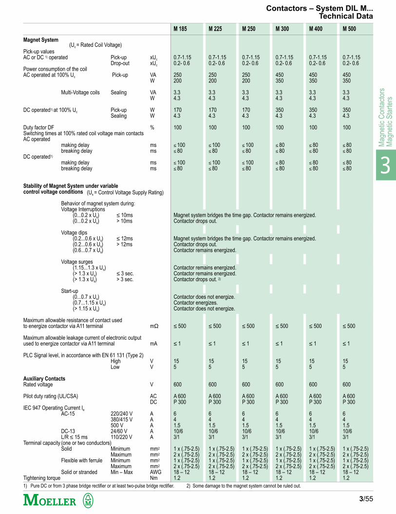
3
Mag
netic
Con
tact
ors
Mag
netic
Sta
rter
s
Magnet System
Pick-up valuesAC or DC 1) operated Pick-up xUc
Drop-out xUc
Power consumption of the coilAC operated at 100% Uc Pick-up VA
W
Multi-Voltage coils Sealing VAW
DC operated1) at 100% Uc Pick-up WSealing W
Duty factor DF %Switching times at 100% rated coil voltage main contactsAC operated
making delay msbreaking delay ms
DC operated1)
making delay msbreaking delay ms
Stability of Magnet System under variable
control voltage conditions
Behavior of magnet system during:Voltage Interruptions
(0...0.2 x Us) ≤ 10ms(0...0.2 x Us) > 10ms
Voltage dips(0.2...0.6 x Us) ≤ 12ms(0.2...0.6 x Us) > 12ms(0.6...0.7 x Us)
Voltage surges(1.15...1.3 x Us)(> 1.3 x Us) ≤ 3 sec.(> 1.3 x Us) > 3 sec.
Start-up(0...0.7 x Us)(0.7...1.15 x Us)(> 1.15 x Us)
Maximum allowable resistance of contact usedto energize contactor via A11 terminal mΩ
Maximum allowable leakage current of electronic outputused to energize contactor via A11 terminal mA
PLC Signal level, in accordance with EN 61 131 (Type 2)High VLow V
Auxiliary Contacts
Rated voltage V
Pilot duty rating (UL/CSA) ACDC
IEC 947 Operating Current Ie
AC-15 220/240 V A380/415 V A500 V A
DC-13 24/60 V AL/R ≤ 15 ms 110/220 V A
Terminal capacity (one or two conductors)Solid Minimum mm2
Maximum mm2
Flexible with ferrule Minimum mm2
Maximum mm2
Solid or stranded Min – Max AWGTightening torque Nm
3/55
1) Pure DC or from 3 phase bridge rectifier or at least two-pulse bridge rectifier. 2) Some damage to the magnet system cannot be ruled out.
M 185 M 225 M 250 M 300 M 400 M 500
Contactors – System DIL M...Technical Data
(Uc = Rated Coil Voltage)
(Us = Control Voltage Supply Rating)
0.7-1.15 0.7-1.15 0.7-1.15 0.7-1.15 0.7-1.15 0.7-1.150.2- 0.6 0.2- 0.6 0.2- 0.6 0.2- 0.6 0.2- 0.6 0.2- 0.6
250 250 250 450 450 450200 200 200 350 350 350
3.3 3.3 3.3 3.3 3.3 3.34.3 4.3 4.3 4.3 4.3 4.3
170 170 170 350 350 3504.3 4.3 4.3 4.3 4.3 4.3
100 100 100 100 100 100
≤ 100 ≤ 100 ≤ 100 ≤ 80 ≤ 80 ≤ 80≤ 80 ≤ 80 ≤ 80 ≤ 80 ≤ 80 ≤ 80
≤ 100 ≤ 100 ≤ 100 ≤ 80 ≤ 80 ≤ 80≤ 80 ≤ 80 ≤ 80 ≤ 80 ≤ 80 ≤ 80
Magnet system bridges the time gap. Contactor remains energized.Contactor drops out.
Magnet system bridges the time gap. Contactor remains energized.Contactor drops out.Contactor remains energized.
Contactor remains energized.Contactor remains energized.Contactor drops out. 2)
Contactor does not energize.Contactor energizes.Contactor does not energize.
≤ 500 ≤ 500 ≤ 500 ≤ 500 ≤ 500 ≤ 500
≤ 1 ≤ 1 ≤ 1 ≤ 1 ≤ 1 ≤ 1
15 15 15 15 15 155 5 5 5 5 5
600 600 600 600 600 600
A 600 A 600 A 600 A 600 A 600 A 600P 300 P 300 P 300 P 300 P 300 P 300
6 6 6 6 6 64 4 4 4 4 41.5 1.5 1.5 1.5 1.5 1.510/6 10/6 10/6 10/6 10/6 10/63/1 3/1 3/1 3/1 3/1 3/1
1 x (.75-2.5) 1 x (.75-2.5) 1 x (.75-2.5) 1 x (.75-2.5) 1 x (.75-2.5) 1 x (.75-2.5)2 x (.75-2.5) 2 x (.75-2.5) 2 x (.75-2.5) 2 x (.75-2.5) 2 x (.75-2.5) 2 x (.75-2.5)1 x (.75-2.5) 1 x (.75-2.5) 1 x (.75-2.5) 1 x (.75-2.5) 1 x (.75-2.5) 1 x (.75-2.5)2 x (.75-2.5) 2 x (.75-2.5) 2 x (.75-2.5) 2 x (.75-2.5) 2 x (.75-2.5) 2 x (.75-2.5)18 – 12 18 – 12 18 – 12 18 – 12 18 – 12 18 – 121.2 1.2 1.2 1.2 1.2 1.2

3
Magnetic C
ontactorsM
agnetic Starters
General
Specifications
Mechanical life-spanAC operated x 106 operationsDC operated x 106 operations
Climatic Test openenclosed
Ambient temperature open max./min. C˚enclosed max./min. C˚
Mounting position
Impact resistance of NO (NC)contacts, Duration 20 ms, (make/break) g
Dimensions mm
Main Contacts
Rated Voltage V
Rated making capacity, ACcos = 0.35 Acos = 1 A
Rated breaking capacity, AC 220-230 V Acos = 0.35 380-400 V A50 – 60 Hz 500 V A
660-690 V A
Contactor life spanAC1, AC3, AC4 ops
Current heat loss (3 poles)At continuous current rating Ith W
Continuous current UL/CSA open A50-60 Hz 3 pole enclosed A
AC 1-duty IEC/EN 60 947Continuous current Ith
∆ Rated operating current Ie
50-60 Hz 3 pole: open Aenclosed A
AC 3-dutyRated operating current Ie
open and enclosed 230 V A50-60 Hz 500 V A
660 V AAC 4-dutyRated operating current Ie
open and enclosed 230 V A50-60 Hz 500 V A
660 V A
Main Terminals
Wire capacity One Conductor(Cu cable) Min. AWG
Max. AWGWire capacity Two Conductors
(Cu cable) Min. AWGMax. AWG
Contactors – DIL UniversalTechnical Data
DIL 3 DIL 4 DIL 6 DIL 8 DIL 8A
3/56
UL, CSA, IEC/EN 60 947, CE , DIN VDE 0660
10-15 10-15 10-15 10-15 11.5 1.5 1.5 0.4 0.4
Damp heat, constant to IEC/EN 60 068, Pt. 2-3Damp heat, cyclic, to IEC/EN 60 068, Pt. 2-30
+50/-25 +50/-25 +50/-25 +50/-25 +50/-25+40/-25 +40/-25 +40/-25 +40/-25 +40/-25
Either vertical or inclined up to 30˚ in any direction from vertical
7(4) 10(8) 13(9) 7(5) 7(5)
See pages 3/61
600 600 600 600 600
1600 2100 2500 2900 37001620 2200 2600 3400 3900
970 1800 2500 2900 3000970 1800 2500 2900 3000800 1700 1900 2900 2900620 1070 1120 1500 1100
Consult Moeller Electric
25 75 116 120 125
140 160 210 360 400126 144 189 324 360
140 225 250 420 500125 170 200 350 400
103 170 204 300 36078 127 182 285 35560 98 140 214 –
52 75 125 180 25054 78 127 182 22042 60 98 140 –
#6 #6 #6 #1/0 #1/0#2/0 250 300 500 500
kcmil kcmil kcmil kcmil#18 #18 #18 #1/0 #1/0#4 #2 #1/0 250 250
kcmil kcmil
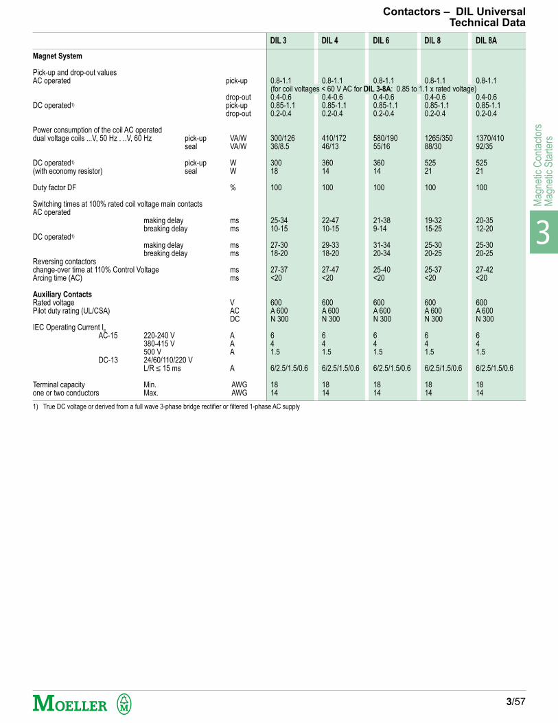
3
Mag
netic
Con
tact
ors
Mag
netic
Sta
rter
s
Magnet System
Pick-up and drop-out valuesAC operated pick-up
drop-outDC operated1) pick-up
drop-out
Power consumption of the coil AC operateddual voltage coils ...V, 50 Hz . ..V, 60 Hz pick-up VA/W
seal VA/W
DC operated1) pick-up W(with economy resistor) seal W
Duty factor DF %
Switching times at 100% rated coil voltage main contactsAC operated
making delay msbreaking delay ms
DC operated1)
making delay msbreaking delay ms
Reversing contactorschange-over time at 110% Control Voltage msArcing time (AC) ms
Auxiliary Contacts
Rated voltage VPilot duty rating (UL/CSA) AC
DCIEC Operating Current Ie
AC-15 220-240 V A380-415 V A500 V A
DC-13 24/60/110/220 VL/R ≤ 15 ms A
Terminal capacity Min. AWGone or two conductors Max. AWG
1) True DC voltage or derived from a full wave 3-phase bridge rectifier or filtered 1-phase AC supply
Contactors – DIL UniversalTechnical Data
3/57
DIL 3 DIL 4 DIL 6 DIL 8 DIL 8A
0.8-1.1 0.8-1.1 0.8-1.1 0.8-1.1 0.8-1.1(for coil voltages < 60 V AC for DIL 3-8A: 0.85 to 1.1 x rated voltage)0.4-0.6 0.4-0.6 0.4-0.6 0.4-0.6 0.4-0.60.85-1.1 0.85-1.1 0.85-1.1 0.85-1.1 0.85-1.10.2-0.4 0.2-0.4 0.2-0.4 0.2-0.4 0.2-0.4
300/126 410/172 580/190 1265/350 1370/41036/8.5 46/13 55/16 88/30 92/35
300 360 360 525 52518 14 14 21 21
100 100 100 100 100
25-34 22-47 21-38 19-32 20-3510-15 10-15 9-14 15-25 12-20
27-30 29-33 31-34 25-30 25-3018-20 18-20 20-34 20-25 20-25
27-37 27-47 25-40 25-37 27-42<20 <20 <20 <20 <20
600 600 600 600 600A 600 A 600 A 600 A 600 A 600N 300 N 300 N 300 N 300 N 300
6 6 6 6 64 4 4 4 41.5 1.5 1.5 1.5 1.5
6/2.5/1.5/0.6 6/2.5/1.5/0.6 6/2.5/1.5/0.6 6/2.5/1.5/0.6 6/2.5/1.5/0.6
18 18 18 18 1814 14 14 14 14

3
Magnetic C
ontactorsM
agnetic Starters
Type
37.5 x 25 x 15(143/4 x 97/8 x 6)
37.5 x 25 x 15(143/4 x 97/8 x 6)
37.5 x 37.5 x 22.5(143/4 x 143/4 x 87/8)
37.5 x 37.5 x 22.5(143/4 x 143/4 x 87/8)
42.1 x 79.6 x 22.5(161/2 x 311/3 x 97/8)
–
–
–––
23 x 40 x 17.5(9 x 153/4 x 7)
27 x 60 x 17.5(105/8 x 231/2 x 7)
50 x 60 x 17.5(195/8 x 231/2 x 7)
50 x 60 x 17.5(195/8 x 231/2 x 7)
50 x 60 x 17.5(195/8 x 231/2 x 7)
50 x 80 x 17.5(195/8 x 311/2 x 7)
80 x 120 x 27.5(311/2 x 471/4 x 10)
17 x 24 x 15(65/8 x 91/2 x 7)
23 x 30 x 17.5(9 x 117/8 x 7)
23 x 40 x 17.5(9 x 153/4 x 7)
27 x 60 x 17.5(105/8 x 231/2 x 7)
50 x 60 x 17.5(195/8 x 231/2 x 7)
50 x 60 x 17.5(195/8 x 231/2 x 7)
50 x 60 x 17.5(195/8 x 231/2 x 7)
50 x 80 x 17.5(195/8 x 311/2 x 7)
80 x 120 x 27.5(311/2 x 471/4 x 10)
18.75 x 25 x 15(73/4 x 97/8 x 6)
37.5 x 25 x 17.5(143/4 x 97/8 x 7)
37.5 x 25 x 22.5(143/4 x 97/8 x 87/8)
37.5 x 37.5 x 22.5(143/4 x 143/4 x 87/8)
37.5 x 37.5 x 22.5(143/4 x 143/4 x 87/8)
42.1 x 79.6 x 27.5(161/2 x 311/3 x 97/8)
42.1 x 79.6 x 25(161/2 x 311/3 x 97/8)
———
17 x 24 x 15(65/8 x 91/2 x 6)
23 x 30 x 17.5(9 x 117/8 x 7)
27 x 60 x 17.5(105/8 x 231/2 x 7)
27 x 60 x 17.5(105/8 x 231/2 x 7)
50 x 80 x 17.5(195/8 x 311/2 x 7)
DIL
(E)EM/ZE-...
00(A)M/11/Z00-...
0M/11/Z00-...
0AM/11/Z00-...
1M/11/Z1-...
1AM/11/Z1-...
2M/11/Z1-...
2AM/11/Z1-...
2AM/11+Z1-75
3M 80/11/Z5
4M 115/11/Z5
3-22/Z4-...
4-22/Z4-...
6-22/Z4-...
8-22/Z4-...
8-22/ZW7-...
8A-22/ZW7-...
3/58
Enclosure Suffix - Dimensional Data
AC MAGNETIC FULL VOLTAGE NON-REVERSING STARTERS (PAGE 3/14)
/Scm (inches)
/SD, /DWcm (inches)
23 x 40 x 17.5(9 x 153/4 x 7)
23 x 40 x 17.5(9 x 153/4 x 7)
27 x 60 x 17.5(105/8 x 231/2 x 7)
27 x 60 x 17.5(105/8 x 231/2 x 7)
50 x 80 x 17.5(195/8 x 311/2 x 7)
/Icm (inches) DIUL...
(E)EM-...
00(A)M-01/Z00-...
0(A)M/11/Z00-...
0(A)M/11+Z1-...
1M/11/Z1-...
1AM/11/Z1-...
2(A)M/11/Z1-...
2AM/11+Z1-75
3M 80/11/Z5-...
4M 115/11/Z5-...
3-22/Z4-...
4-22/Z4-...
6-22/Z4-...
8-22/Z4-...
8-22/ZW7-...
8A-22/ZW7-...
AC MAGNETIC FULL VOLTAGE REVERSING STARTERS (PAGE 3/15)
Type
/Scm (inches)
/SD, /DWcm (inches)
/Icm (inches)
Enclosure - w x h x d Enclosure - w x h x d

3
Mag
netic
Con
tact
ors
Mag
netic
Sta
rter
s
/SD, /DWcm (inches)
Enclosure - w x h x d
/Icm (inches)
/SD, /DWcm (inches)
Enclosure - w x h x d
27 x 60 x 17.5(101/2 x 231/2 x 7)
MW
00M/11/P2-30 /Z00-.../S
00AM/11/P2-30 /Z00-.../S
0M/11/P2-30 /Z00-.../S
0AM/11/P2-30 /Z00-.../S
0AM/11/P2-60 /Z1-.../S
1M/11/P2-60 /Z1-.../S
1M/11/P2-30 /Z1-40/S
1M/11/P2-60 /Z1-40/S
1AM/11/P2-60 /Z1-.../S
2M/11/P2-60 /Z1-57/S
2M/11/P2-100 /Z1-57/S
2AM/11/P2-100 /Z1-.../S
2AM/11/P2-100 /Z4-.../S
M
00M/11/P2-30 /Z00-.../S
00AM/11/P2-30 /Z00-.../S
0M/11/P2-30 /Z00-.../S
0AM/11/P2-30 /Z00-.../S
0AM/11/P2-60 /Z1-.../S
1M/11/P2-60 /Z1-.../S
1M/11/P2-30 /Z1-40/S
1M/11/P2-60 /Z1-40/S
1AM/11/P2-60 /Z1-.../S
2M/11/P2-60 /Z1-57/S
2M/11/P2-100 /Z1-57/S
2AM/11/P2-100 /Z1-.../S
2AM/11/P2-100 /Z4-.../S
37.5 x 25 x 12.5(143/4 x 97/8 x 6)
COMBINATION STARTERS – SELF-PROTECTED TYPE, FVNR (PAGE 3/20)
MV
00M-01/ZM/Z00-...
00AM-01/ZM/Z00-...
0M/11/ZM/Z00-...
0AM/11/ZM6/Z-...
1M/11/ZM6/Z1-40
2M/11/ZM6/Z1-...
2AM/11/ZM6/Z1-...
3M 80/11/ZM6/Z5-...
4M 115/11/ZM6/Z5-...
4M 115/11/ZM9/Z5-...
3-22/ZM6/Z4-...
4-22/ZM6/Z4-...
4-22/ZM9/Z4-140
6-22/ZM9/Z4-...
8-22/ZM9/Z4-...
8-22/ZM10/Z4-...
8-22/ZM10/ZW7-...
8A-22/ZM10/ZW7-...
COMBINATION REVERSING STARTERS - BREAKER TYPE (PAGE 3/23)
M
00(A)M-10/ZM/Z00-...
0M/11/ZM/Z00-...
0AM/11/ZM6/Z-...
1M/11/ZM6/Z1-40
2M/11/ZM6/Z1-57
2AM/11/ZM6/Z1-...
3M 80/11/ZM6/Z5
4M 115/11/ZM6/Z5
4M 115/11/ZM9/Z5
3-22/ZM6/Z4-...
3-22/ZM6/Z4-100
4-22/ZM6/Z4-...
4-22/ZM6/Z4-140
4-22/ZM9/Z4-140
6-22/ZM9/Z4-...
8-22/ZM9/Z4-240
8-22/ZM10/ZW7-...
8A-22/ZM10/ZW7-...
The enclosure may or not change with the addition of modifications. When accuratedimensions of the enclosure are required, refer to your nearest Moeller Electric Office.
27 x 60 x 17.5(101/2 x 231/2 x 7)
27 x 60 x 17.5(101/2 x 231/2 x 7)
27 x 60 x 17.5(101/2 x 231/2 x 7)
50 x 60 x 17.5(191/2 x 231/2 x 7)
60 x 80 x 17.5(231/2 x 311/2 x 7)
60 x 80 x 17.5(231/2 x 311/2 x 7)
80 x 120 x 27.5(311/2 x 471/4 x 11)
37.5 x 25 x 15(143/4 x 97/8 x 6)
37.5 x 25 x 17.5(143/4 x 97/8 x 7)
37.5 x 37.5 x 22.5(143/4 x 143/4 x 87/8)
42.1 x 79.6 x 22.5(165/8 x 313/8 x 87/8)
––
–––
Enclosure Suffix - Dimensional Data
COMBINATION STARTERS - BREAKER TYPE (PAGE 3/22)
Type
/Scm (inches)
23 x 40 x 17.5(9 x 153/4 x 7)
27 x 60 x 17.5(101/2 x 231/2 x 7)
50 x 60 x 17.5(195/8 x 231/2 x 7)
50 x 60 x 17.5(195/8 x 231/2 x 7)
80 x 100 x 27.5(311/2 x 393/8 x 11)
/SD, /DWcm (inches)
23 x 40 x 17.5(9 x 153/4 x 7)
27 x 60 x 17.5(101/2 x 231/2 x 7)
50 x 60 x 17.5(195/8 x 231/2 x 7)
50 x 60 x 17.5(195/8 x 231/2 x 7)
80 x 100 x 27.5(311/2 x 393/8 x 11)
/Icm (inches)
37.5 x 25 x 15(143/4 x 97/8 x 6)
37.5 x 37.5 x 17.5(143/4 x 143/4 x 7)
37.5 x 37.5 x 17.5(143/4 x 143/4 x 7)
42.1 x 79.6 x 22.5(165/8 x 313/8 x 87/8)
42.1 x 79.6 x 22.5(165/8 x 313/8 x 87/8)
–––
––––
27 x 60 x 17.5(101/2 x 231/2 x 7)
27 x 60 x 17.5(101/2 x 231/2 x 7)
27 x 60 x 17.5(101/2 x 231/2 x 7)
50 x 60 x 17.5(191/2 x 231/2 x 7)
60 x 80 x 17.5(231/2 x 311/2 x 7)
60 x 80 x 17.5(231/2 x 311/2 x 7)
80 x 120 x 27.5(311/2 x 471/4 x 11)
Type
/Scm (inches)
PKZ 2/ZM.../S-SP 23 x 40 x 17.5(9 x 153/4 x 7)
23 x 40 x 17.5(9 x 153/4 x 7)
COMBINATION STARTERS – DISCONNECT TYPE (PAGE 3/24)
Type
/Scm (inches)
/SD, /DWcm (inches)
27 x 60 x 17.5(101/2 x 231/2 x 7)
27 x 60 x 17.5(101/2 x 231/2 x 7)
COMBINATION REVERSING STARTERS – DISCONNECT TYPE (PAGE 3/26)
Type
/Scm (inches)
27 x 60 x 17.5(101/2 x 231/2 x 7)
3/59
Enclosure - w x h x d
Type
/Scm (inches)
/SD, /DWcm (inches)
/Icm (inches)
Enclosure - w x h x d
Enclosure - w x h x d

3
Magnetic C
ontactorsM
agnetic Starters
/SD, /DWcm (inches)
23 x 40 x 17.5(9 x 153/4 x 7)
27 x 60 x 17.5(101/2 x 231/2 x 7)
50 x 60 x 17.5(195/8 x 231/2 x 7)
50 x 80 x 17.5(195/8 x 311/2 x 7)
80 x 120 x 27.5(311/2 x 471/4 x 11)
2S2W 00M/Z00-.../Z00-...
2S2W 00AM/Z00-.../Z00-...
2S2W 0M/Z00-.../Z00-...
2S2W 0AM/Z00-.../Z00-...
2S2W 1M/Z1-.../Z1-...
2S2W 1AM/Z1-.../Z1-...
2S2W 2M/Z1-.../Z1-...
2S2W 2AM/Z1-.../Z1-...
2S2W 3-22/Z1-.../Z1-...
2S2W 4-22/Z4-.../Z1-...
2S2W 6-22/Z4-.../Z1-...
2S2W 8-22/Z4-.../Z1-...
2S2W 8-22/Z4-.../Z4-...
2S2W 8-22/ZW7-.../Z4-...
2S2W 8A-22/ZW7-.../Z4-...
/SD, /DWcm (inches)
23 x 40 x 17.5(9 x 153/4 x 7)
27 x 60 x 17.5(101/2 x 231/2 x 7)
50 x 80 x 17.5(195/8 x 311/2 x 7)
60 x 100 x 17.5(231/2 x 393/8 x 7)
80 x 120 x 27.5(311/2 x 471/4 x 11)
2S1W 00M/Z00-.../Z00-...
2S1W 00AM/Z00-.../Z00-...
2S1W 0M/Z00-.../Z00-...
2S1W 0AM/Z00-.../Z00-...
2S1W 1M/Z1-.../Z1-...
2S1W 1AM/Z1-.../Z1-...
2S1W 2M/Z1-.../Z1-...
2S1W 2AM/Z1-.../Z1-...
2S1W 3-22/Z1-.../Z1-...
2S1W 4-22/Z4-.../Z1-...
2S1W 6-22/Z4-.../Z1-...
2S1W 8-22/Z4-.../Z1-...
2S1W 8-22/Z4-.../Z4-...
2S1W 8-22/ZW7-.../Z4-...
2S1W 8A-22/ZW7-.../Z4-...
Type
3/60
Enclosure Suffix - Dimensional Data
AC MAGNETIC TWO-SPEED STARTER – 1 WINDING (PAGE 3/16)
/Scm (inches)
23 x 40 x 17.5(9 x 153/4 x 7)
27 x 60 x 17.5(101/2 x 231/2 x 7)
50 x 80 x 17.5(195/8 x 311/2 x 7)
60 x 100 x 17.5(231/2 x 393/8 x 7)
80 x 120 x 27.5(311/2 x 471/4 x 11)
AC MAGNETIC TWO-SPEED STARTER – 2 WINDING (PAGE 3/16)
Type
/Scm (inches)
23 x 40 x 17.5(9 x 153/4 x 7)
27 x 60 x 17.5(101/2 x 231/2 x 7)
50 x 60 x 17.5(195/8 x 231/2 x 7)
50 x 80 x 17.5(195/8 x 311/2 x 7)
80 x 120 x 27.5(311/2 x 471/4 x 11)
Enclosure - w x h x d Enclosure - w x h x d

3
Mag
netic
Con
tact
ors
Mag
netic
Sta
rter
s
Contactors – StartersDimensions
DIL E(E)M-...DIL E(E)M-...-G
DIL 00M to DIL 2AMDIL 00M-G to DIL 2AM-G
Maintain a minimum spacing of 5 mm betweenDC operated DIL 00M-G toDIL 2AM-G contactors mounted side by side.
DIL 3M 80DIL 4M 115
DIL 3M 80 + Z5-.../SK3DIL 4M 115 + Z5-.../SK4
a4 = With side mounting auxiliary contact module on DIL 0M toDIL 2AM, with second side mounting auxiliary contact moduletype DIL M 820-XHI11-SA on DIL 3M 80 to DIL 4M 115
a5 = With N DIL...M 4th pole modulec1 = With ...DIL M auxiliary contact modulec2 = With TP...11 DIL pneumatic timer modulec3 = With V(-G) DIL mechanical latching module
3/61
35
58
83
52
50
M4
45
a3
a
a4
a5c2, c3
c1
c
b3
4,7
b
b1
min. 12c6
MDEMDE...
a2 b4
b2
a1
a3 c6
b3
b6
a1
b5
a2
MDE
a7
b4
b2
a1
(-G)(-G)
(60)(50)(70)(80)(98)(49)(75)(122)–(155)(184)–
(42)(60)(153)(26)(116)
DIL
aa1a4a5bb1b2c (w/out H DIL)c (with H DIL)c1c2c3
OverloadRelays
Z
a2a3b3b4c6
00 M00 AM00 M 4
4535––7739607476.5107136136
00
34451201990
(-G)(-G)(-G)
(45)(35)––(77)(39)(60)(99)(101.5)(132)(161)(161)
(34)(45)(120)(19)(115)
0 M0 AM
453555609146757986.3112141–
00
34451331896
(-G)(-G)
(45)(35)(55)(60)(91)(46)(75)(104)(113.3)(137)(166)–
(34)(45)(133)(18)(121)
1 M1 AM
6050708098497597–130159–
1
42601532691
2 M2 AM
706080901185990102–135164–
1
47601712791
(-G)(-G)
(70)(60)(80)(90)(118)(59)(90)(127)–(160)(189)–
(47)(60)(171)(27)(116)
DIL
aa1a4bb1b2c (w/out H DIL)c4c5
OverloadRelays
Z
a2a3a7b3b4b5b6c6
3 M 80
10080112130651101277720
5-.../SK 3
5710080238517495125
4 M 115
120100130150751301377947
5-.../SK 4
67120802635674100125
2 M4 x 16 2 M5 x 16
00 (A)M 1 (A)M
0 (A)M 2 (A)M
2 M5 x 20 2 M6 x 20DIL 3M 80 DIL 4M 115
Z 5-.../SK 3 Z 5-.../SK 4
a4
c
b
b1
a c5
c4
8
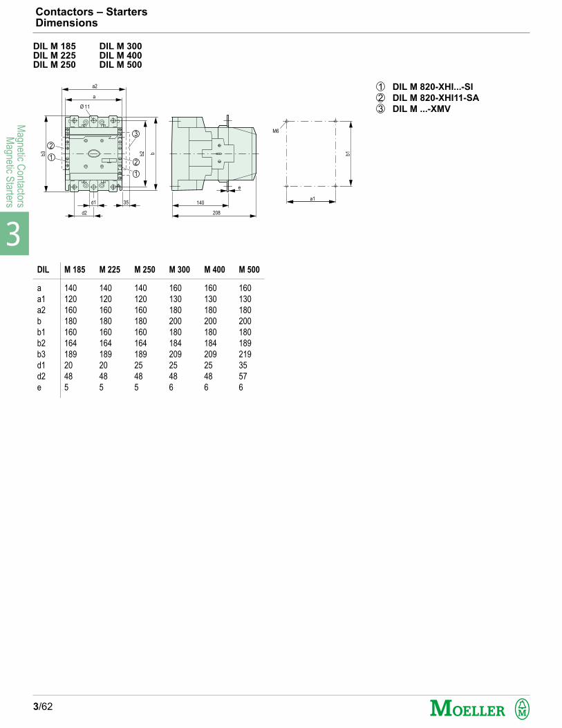
3
Magnetic C
ontactorsM
agnetic Starters
Contactors – StartersDimensions
3/62
DIL M 185 DIL M 300DIL M 225 DIL M 400DIL M 250 DIL M 500
208
140
b1
a1
M6
e
d1 35
b2b3 b
d2
a
Ø 11
a2
1
21
2
3
1 DIL M 820-XHI...-SI
2 DIL M 820-XHI11-SA
3 DIL M ...-XMV
DIL
a
a1
a2
b
b1
b2
b3
d1
d2
e
M 185
140
120
160
180
160
164
189
20
48
5
M 225
140
120
160
180
160
164
189
20
48
5
M 250
140
120
160
180
160
164
189
25
48
5
M 300
160
130
180
200
180
184
209
25
48
6
M 400
160
130
180
200
180
184
209
25
48
6
M 500
160
130
180
200
180
189
219
35
57
6
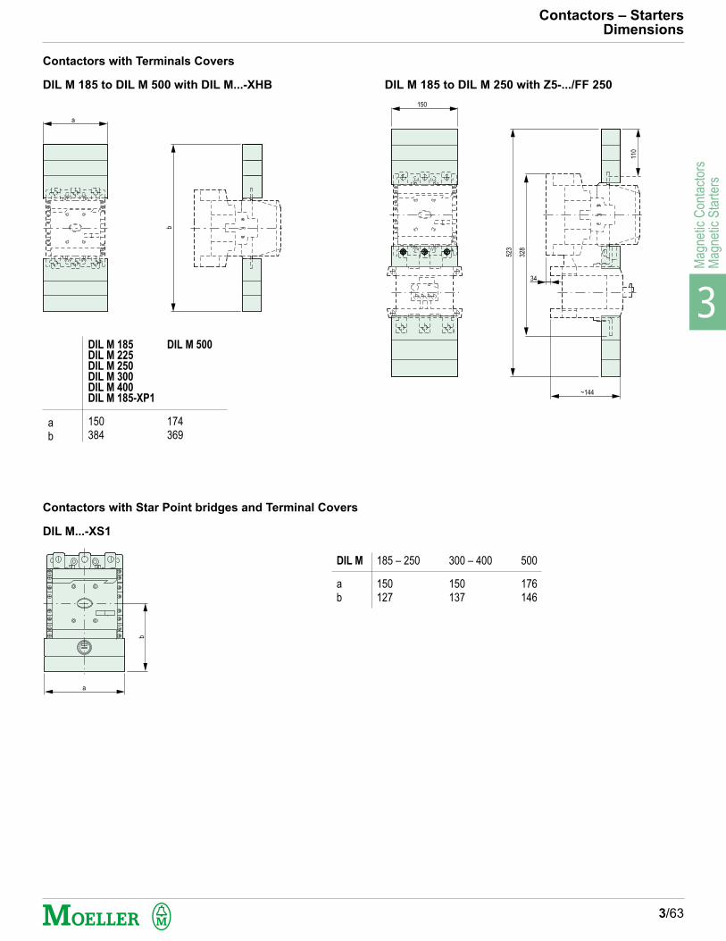
3
Mag
netic
Con
tact
ors
Mag
netic
Sta
rter
s
Contactors – StartersDimensions
3/63
Contactors with Terminals Covers
DIL M 185 to DIL M 500 with DIL M...-XHB DIL M 185 to DIL M 250 with Z5-.../FF 250
Contactors with Star Point bridges and Terminal Covers
DIL M...-XS1
a
b
a
b
DIL M
ab
185 – 250
150127
300 – 400
150137
500
176146
150
34
523
110
328
~144
ab
DIL M 185DIL M 225DIL M 250DIL M 300DIL M 400DIL M 185-XP1
150384
DIL M 500
174369

3
Magnetic C
ontactorsM
agnetic Starters
Contactors – StartersDimensions
3/64
DIL 3-22/Z4DIL 4-22/Z4DIL 6-22/Z4DIL 8-22/Z4DIL 8A-22/Z4
DIL 8-22/ZW7DIL 8A-22/ZW7
Universal Contactors
Reset ButtonMDE-287
DILZ
a = bca1 = b1a2b2hikb3
3-224.../K 3
136131118701275425414152
4-224...
158141136701475827823176
6-224...
182150150701665729630200
8(A)-224.../K 8
230190192902116935351252
c
148..212
a1
b1b3b
b2
i
a2
h
a
138
145
13.5
MDE
h1-Z4
Z4-
HV-DIL...
k
Db
M5
DIL 8 (A)-22
3 M5x2 DIL 8 (A)-22: 4 M5x20
69
A
B A-B
...IG
a‘ b‘
8(A)-22/G
6510
Minimum clearance a' and b' between DIL.../G and neighboringcomponents
DIL
a'b'
3-22/G
6515
4-22/G
6515
6-22/G
6515
9021
1
353
200
Max. 11 x 21 x 1
52
230
252
230
19013.5
hV-DIL 8
ZW7
172...250
MD
E
19219
2
M5
M4
78
4
26
18544
MDE
4 M5 x 20
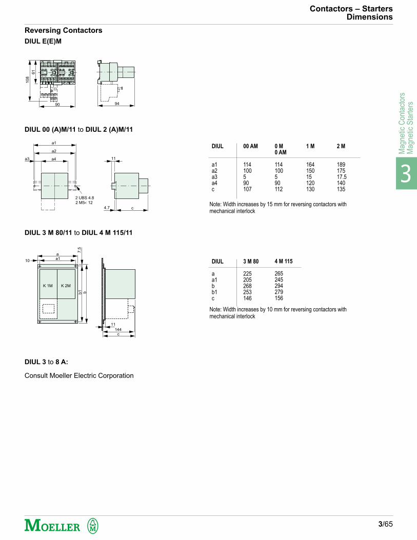
3
Mag
netic
Con
tact
ors
Mag
netic
Sta
rter
s
Contactors – StartersDimensions
3/65
Reversing Contactors
DIUL 00 (A)M/11 to DIUL 2 (A)M/11
DIUL 3 M 80/11 to DIUL 4 M 115/11
DIUL 3 to 8 A:
Consult Moeller Electric Corporation
DIUL
a1a2a3a4c
00 AM
114100590107
0 M
0 AM
114100590112
1 M
16415015120130
DIUL
aa1bb1c
3 M 80
225205268253146
61
10
8
90 94
11
c4.7
a4
a2
a1
a3
2 UBS 4.8
2 M5 12
7,5
a
a1
11
144
c
b1 b
K 1M K 2M
10 4 M 115
265245294279156
2 M
18917517.5140135
Note: Width increases by 15 mm for reversing contactors withmechanical interlock
Note: Width increases by 10 mm for reversing contactors withmechanical interlock
DIUL E(E)M

3
Magnetic C
ontactorsM
agnetic Starters
H DIL E
Tamper-proof Transparent Cover
43
45
58
69
45
Contactors – StartersDimensions
3/66
Surge SuppressorsRC B DIL...RC S DIL...FD B DIL...VG B DIL...VG C DIL...
VS1 DILVS2 DIL
ETS 4-VS 3
P1 DIL EM P1 DIL... M
AK DIL...M
RC DIL EVG DIL E
5245
62,5
abc
VS1 DIL
VS2 DIL
452655
Interface Modules
a
b
c 103
98
78
22,5
82
,5
Paralleling Bridges
c
b
a
40
65,5
83,5
c1
S1 DIL...M
Star-point Bridges
a
c1
Adapter
b
a c
d
36
Type
S1 DIL 00M
S1 DIL 0M
S1 DIL 1M
S1 DIL 2M
S1 DIL 3M
S1 DIL 4M
a
7791106126150169
c1
656979799293
For Type DIL...
00(A)M(-G)
0(A)M(-G)
1(A)M(-G)
2(A)M(-G)
3M 80
4M 115
a
95114170188195244
b
5–9121917
c
91103138138150182
(116)(128)(163)(163)
c1
656979798892
(90)(94)(101)(101)
RC B DIL
331530
RC S DIL
331530
FD B DIL
331530
abc
VG B DIL
331530
VG C DIL
38833
Type
For DIL
abcd
AK DIL...
3M 80
89160887
4M 115
94190918.4
a c
b
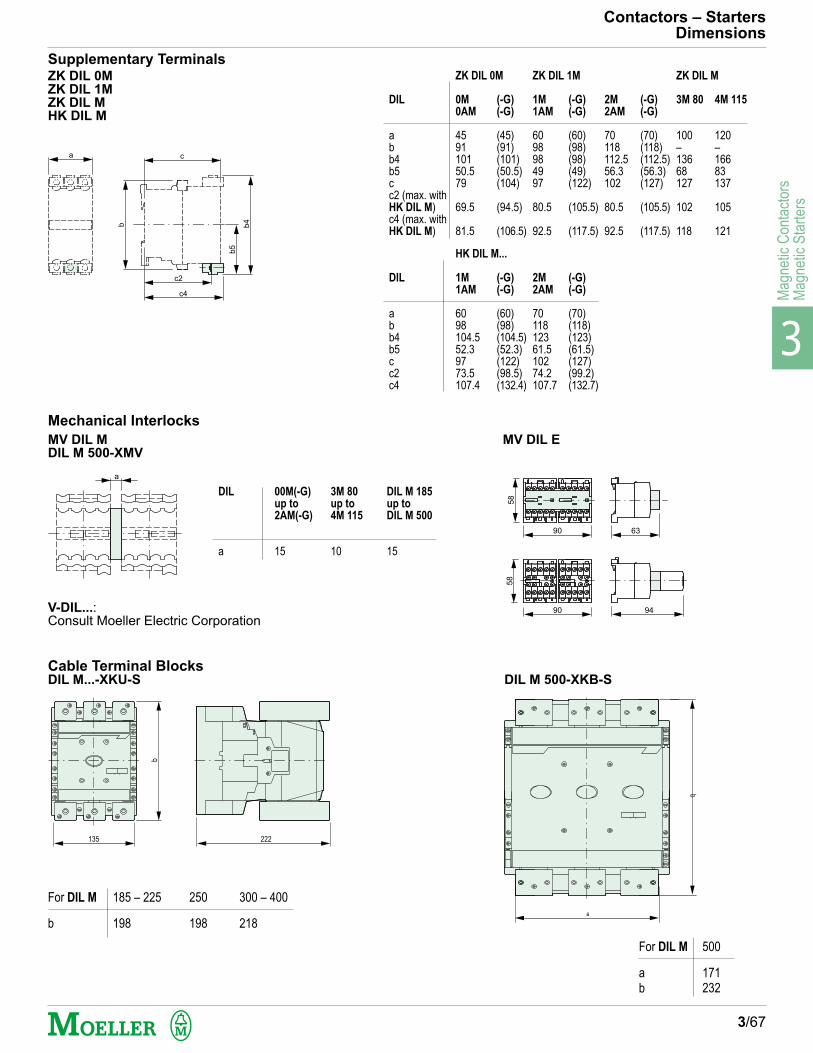
3
Mag
netic
Con
tact
ors
Mag
netic
Sta
rter
s
Contactors – StartersDimensions
3/67
ZK DIL 0MZK DIL 1MZK DIL MHK DIL M
MV DIL MDIL M 500-XMV
Supplementary Terminals
c
c2
c4
b5
b4
b
a
MV DIL E
Mechanical Interlocks
a
DIL
a
00M(-G)
up to
2AM(-G)
15
3M 80
up to
4M 115
10
DIL M 185
up to
DIL M 500
15
90
90 94
63
58
58
V-DIL...:Consult Moeller Electric Corporation
Cable Terminal BlocksDIL M...-XKU-S DIL M 500-XKB-S
135 222
b
a
d
DIL
abb4b5cc2c4
HK DIL M...
1M
1AM
6098104.552.39773.5107.4
2M
2AM
7011812361.510274.2107.7
(-G)
(-G)
(70)(118)(123)(61.5)(127)(99.2)(132.7)
(-G)
(-G)
(60)(98)(104.5)(52.3)(122)(98.5)(132.4)
300 – 400
218
For DIL M
b
185 – 225
198
250
198
For DIL M
ab
500
171232
DIL
abb4b5cc2 (max. withHK DIL M)c4 (max. withHK DIL M)
ZK DIL 0M
0M
0AM
459110150.579
69.5
81.5
ZK DIL 1M
1M
1AM
6098984997
80.5
92.5
(-G)
(-G)
(60)(98)(98)(49)(122)
(105.5)
(117.5)
2M
2AM
70118112.556.3102
80.5
92.5
(-G)
(-G)
(70)(118)(112.5)(56.3)(127)
(105.5)
(117.5)
ZK DIL M
3M 80
100–13668127
102
118
(-G)
(-G)
(45)(91)(101)(50.5)(104)
(94.5)
(106.5)
4M 115
120–16683137
105
121

3
Magnetic C
ontactorsM
agnetic Starters
Notes
3/68