maharashtra state board of technical...
TRANSCRIPT

MAHARASHTRA STATE BOARD OF TECHNICAL EDUCATION
(Autonomous)
(ISO/IEC-27001-2005 Certified)
Winter – 2015 Examinations
Subject Code: 17414 (IIN) Model Answer Page No: 1 of 25
Important Instructions to examiners:
1) The answers should be examined by key words and not as word-to-word as given in the model answer
scheme.
2) The model answer and the answer written by candidate may vary but the examiner should assess the
understanding level of the candidate.
3) The language errors such as grammatical, spelling errors should not be given importance (Not applicable
for subject English and Communication Skills).
4) While assessing figures, examiner may give credit for principal components indicated in the figure. The
figures drawn by candidate and model answer may vary. The examiner should give credit for any
equivalent figure/figures drawn.
5) Credits to be given step wise for numerical problems. In some cases, the assumed constant values may
vary and there may be some difference in the candidate’s answers and model answer (as long as the
assumptions are not incorrect).
6) In case of some questions credit may be given by judgment on part of examiner of relevant answer based
on candidate’s understanding.
7) For programming language papers, credit may be given to any other program based on equivalent
concept

MAHARASHTRA STATE BOARD OF TECHNICAL EDUCATION
(Autonomous)
(ISO/IEC-27001-2005 Certified)
Winter – 2015 Examinations
Subject Code: 17414 (IIN) Model Answer Page No: 2 of 25
1 Attempt any TEN of the following : 20
1 a) Define accuracy and tolerance.
Ans:
Accuracy: The degree of exactness (closeness) of a measurement compared to the
expected (desired) value. OR
It is the ability of a device or a system to respond to a true value of a measured
variable under reference conditions. OR
Closeness with which the instrument reading approaches the true value of the
quantity being measured is known as accuracy.
Tolerance : Ability of an item or system to withstand high levels of stress or
overloading without suffering irreparable harm. OR
Allowable departure from a specification or standard, considered non-harmful to
the functioning of a part, process, or product over its life cycle.
OR
The difference between standard instrument reading and measuring instrument
reading is known as error and if this error is permissible then it is called as
tolerance.
1 mark
1 mark
1 b) Give two examples of active and passive transducer.
Ans: Active Transducers
1. Thermocouple
2. Piezoelectric Transducer
3. Solar Cell/ Photovoltaic cell
4. Tacho generator
Passive Transducers :
1. Thermistor
2. RTD
3. LVDT
4. Strain Gauge
5. Electromagnetic flowmeter.
6. Capacitive transducers. Etc.
Or Any other relevant example.
1 mark
[½ mark/
example]
1 mark
[½ mark/
example]
1 c) Draw the pin configuration of IC74l OP-AMP.
Ans :
OR
[½ mark
per 2 pin
labelling]
.
1 d) Define the following.
(i) CMMR (ii) Slew rate
Ans :

MAHARASHTRA STATE BOARD OF TECHNICAL EDUCATION
(Autonomous)
(ISO/IEC-27001-2005 Certified)
Winter – 2015 Examinations
Subject Code: 17414 (IIN) Model Answer Page No: 3 of 25
CMMR:-The CMRR is defined as the ratio of the powers of the differential gain
over the common-mode gain, measured in positive decibels (thus using the 20 log
rule): As differential gain should exceed common-mode gain, this will be a positive
number, and the higher the better.
𝐶𝑀𝑅𝑅 = 𝐴𝐷𝑀
𝐴𝐶𝑀
OR
It is defined as the ratio of differential voltage gain Ad to common mode voltage
gain Acm.
Slew Rate: - Maximum rate of change of output voltage for a large, overloading
input step. OR
It is defined as the maximum rate of change of output voltage per unit time.
𝑆𝑅 =𝑑𝑉𝑜
𝑑𝑡|𝑚𝑎𝑥𝑖𝑚𝑢𝑚 𝑉/𝜇𝑠𝑒𝑐
1 mark
1 mark
1 e) Draw the input / output characteristics for sensitivity drift and zero drift.
Ans:
1 mark
Per
character-
ristic
[total 2
marks]
1 f) State seebeck effect.
Ans: Seebeck effect: - The Seebeck effect is a phenomenon in which a temperature difference
between two dissimilar electrical conductors or semiconductors produces a voltage
difference between the two substances. If the two conductors or semiconductors are
connected together through an electrical circuit, direct current (DC) flows through that
circuit. OR
When two conductors of dissimilar metals are joined together to form a loop
(thermocouple) and two unequal temperatures T1 and T2 are interposed at two junctions J1
and J2, respectively, Then an infinite resistance voltmeter detects the electromotive force
E, or if a low resistance ammeter is connected, a current flow I is measured
2 marks
1 g) List four factors to be considered while selecting a transducer.
Ans:
1. Operating Principle
2. Sensitivity
3. Operating Range
4. Accuracy
5. Cross Sensitivity
6. Errors
any 4 four
[½ mark/
factor]
[Total 2
marks]
MAHARASHTRA STATE BOARD OF TECHNICAL EDUCATION
(Autonomous)
(ISO/IEC-27001-2005 Certified)
Winter – 2015 Examinations
Subject Code: 17414 (IIN) Model Answer Page No: 4 of 25
7. Transient And Frequency Response
8. Loading Effect
9. Static Characteristic
10. Ruggedness
1 h) State the working principle of turbine flow meter.
Ans:
Principle: The flowing fluid impinges on the turbine blades (rotor), imparting a
force to the blade surface which causes the rotation of the rotor. The speed of the
rotation is directly proportional to the fluid velocity. The rotar consist of small
permanent magnets. When rotar rotates this magnetic field also rotates. The speed
of rotation monitored in most of the meters by magnetic pickup coil, which
generates pulses. Total number of pulses gives the total flow. So the amount of emf
induced depends upon the flow rate.
2 marks
i) List two types of signal converters.
Ans:
1. Voltage to Current converter.
2. Current to Voltage converter.
3. Digital to analog Converter.
4. Analog to Digital Converter.
5. Voltage to frequency converter.
Any 2,
[2 marks]
j) Name the metals used for resistance thermometer.
Ans :
1. Copper
2. Platinum
3. Nickel
4. Tungsten
5. Gold
Any 2,
[2 marks]
k) List four dynamic characteristics.
Ans :
1. Speed of response
2. Lag
3. Fidelity
4. Dynamic error
½ mark
each
[Total 2
marks]
l) List two advantages of electrical transducer.
Ans :
1. Electrical signals can be easily attenuated or amplified and can be bought up
to the level suitable for various devices.
2. The power requirement of transducers is very small.
3. The electrical output of transducer can be easily used, transmitted and
processed for the purpose of measurement.
4. The reduced effect of friction and other mechanical nonlinearities.
5. Due to IC technology, electrical & electronic systems are compact, having
less weight and compact.
6. Reduce effect of mass inertia problems
1 mark per
advantage
Any 2,
[2 marks]

MAHARASHTRA STATE BOARD OF TECHNICAL EDUCATION
(Autonomous)
(ISO/IEC-27001-2005 Certified)
Winter – 2015 Examinations
Subject Code: 17414 (IIN) Model Answer Page No: 5 of 25
2
2 a) Draw the block diagram of instrumentation system and state the function of each
component.
Ans:
Primary Sensing Element: primary sensing element of system is that which first
receives energy from the measured medium and produces an output depending in
some way on the value of measured quantity.
Variable Conversion Element: A variable conversion element merely converts the
output signal of the primary sensing element into a more suitable variable or
condition useful to the function of the instruments.
Variable Manipulation Element: It manipulates the signal represented by some
physical variable, to perform the intended task of an instrument. In the
manipulation process, the physical nature of the signal is preserved.
Data Transmission Element: It transmits the data from one element to other
element.
Data presentation Element: It performs the translation function, such as the
simple indication of a pointer moving over a scale or recording of a pen moving
over a chart.
2 marks
2 marks
2 b) Explain the working of an electromagnetic flow meter with neat diagram.
Ans:
It consist basically a pair of insulated
electrodes buried flush in the opposite
sides of a non- conducting , nonmagnetic
pipe carrying the liquid whose flow is to be
measured.
The pipe is surrounded by an
electromagnet which produces a magnetic
field. The arrangement is analogous to a
conductor moving across a magnetic field.
Therefore, voltage is included across the
electrode. This voltage is given by:-
E= Blv volt
where B= flux x density; Wb/m2,
2 marks

MAHARASHTRA STATE BOARD OF TECHNICAL EDUCATION
(Autonomous)
(ISO/IEC-27001-2005 Certified)
Winter – 2015 Examinations
Subject Code: 17414 (IIN) Model Answer Page No: 6 of 25
l = length of conductor = diameter of pipe; m,
And v = Velocity of conductor (flow); m/s
Thus, assuming a constant magnetic field, the magnitude of the voltage
appearing across the electrode will be directly proportional to velocity.
Thus conductor (liquid in motion) cuts the magnetic field, hence emf is
induced in the liquid. This emf is collected by two electrodes which is
proportional to the flow rate of liquid.i.e.rate of cut of flux.
2 marks
2 c) Label the pin No I to 8 of pin diagram of LF 398 as shown in Fig No. 1.
Ans:
PIN 1 ---- +Vcc
PIN 2 ---- Offset
PIN 3 ---- +Vinput
PIN 4 ---- +VEE
PIN 5 ---- Output
PIN 6 ---- Hold Capacitor
PIN 7 ---- Ground (logic reference)
PIN 1 ---- Hold Signal (Logic Input)
[½ mark
per 1 pin
labeling]
2 d) Draw constructional diagram of LVDT. State its working principle.
Ans:
Principle: It works on the principle of variable inductance. The inductance is
varied according to the displacement. This is achieved either by varying the mutual
inductance between the two coils. It is having a primary & two secondary windings
wound over a hollow former and a soft iron core slides inside the hollow former.
The position of movable core determines the flux linkage between the AC excited
primary winding and each of the secondary winding.
2 marks
2 marks

MAHARASHTRA STATE BOARD OF TECHNICAL EDUCATION
(Autonomous)
(ISO/IEC-27001-2005 Certified)
Winter – 2015 Examinations
Subject Code: 17414 (IIN) Model Answer Page No: 7 of 25
2 e) Define the following terms.
(i) Precision , (ii) Resolution, (iii) Measuring lag, (iv) Dynamic error
Ans:
1. Precision: It is the measure of consistency or repeatability of
measurements.
OR
The closeness with which the individual measurements are departed or
distributed about the average of number of measured value.
2. Resolution: Resolution is the term used to describe the number of dots, or
pixels, used to display an image. The smallest to be distinguished magnitude
from the measured value.
OR
The smallest change in a measured variable to which an instrument will
respond is called resolution. OR
If input to an instrument is varied slowly from any arbitrary (non-zero)
value, the output does not change at all until a certain increment is
exceeded. This increment is called as resolution.
3. Measuring lag: Every system takes some time, whatever small it may be, to
respond to the change in the measured variable. This retardation or delay in
the response of a system is called measurement lag.
4. The dynamic error: It represents a measure of the inability of a system to
adequately reproduce the amplitude of the input signal for a particular input
frequency.
OR
It is the difference between the true value of the variable to be measured,
changing with time and the value indicated by the measurement system.
1mark each
characterist
ic
2 f) Compare open loop and closed loop configuration of OP-AMP with neat diagram.
(Any four points)
Ans :
S.N. Open Loop OPAMP Closed Loop OPAMP
1. Circuit
Diagram
2. Gain Voltage gain is very high.
Gain is uncontrollable.
Voltage gain is low as
compared to open loop. Gain
is controllable & depends on
external passive components.
3. Bandwidth Bandwidth is low Bandwidth is high
4. Application Comparator, square wave
generator,waveshaping
circuits
It is used in ac,dc signal
amplifier, oscillator
,Instrument amplifier circuits
etc.
1 mark
each point
[total 4
marks]
MAHARASHTRA STATE BOARD OF TECHNICAL EDUCATION
(Autonomous)
(ISO/IEC-27001-2005 Certified)
Winter – 2015 Examinations
Subject Code: 17414 (IIN) Model Answer Page No: 8 of 25
5. No feedback is taken
from output
A feedback signal is taken
from output
3 Attempt any FOUR of the following: 16
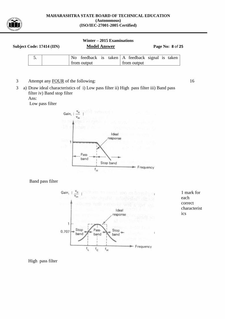
3 a) Draw ideal characteristics of i) Low pass filter ii) High pass filter iii) Band pass
filter iv) Band stop filter
Ans:
Low pass filter
Band pass filter
High pass filter
1 mark for
each
correct
characterist
ics

MAHARASHTRA STATE BOARD OF TECHNICAL EDUCATION
(Autonomous)
(ISO/IEC-27001-2005 Certified)
Winter – 2015 Examinations
Subject Code: 17414 (IIN) Model Answer Page No: 9 of 25
Band stop filter
(Note-Dashed line represents ideal characteristics of the filter)
3 b) Draw and explain block diagram of multichannel DAS.
Ans:
It consists of multiple input sensors or transducers to sense various input
parameters.
Output of each transducer is signal conditioned so as to get a standardized
instrumentation signal.
It allows multiplexing of multiple channel sensors. Analog scanner or multiplexer
select any one input at a time.
A number of channels are used according to the number of inputs.
S/H circuit is used to store one signal which other in ADC which speed up
conversion and increases overall efficiency of DAS
Digital output of ADC is processed in data processing unit.
2 Marks for
diagram
&
2 Marks for
suitable
Explanatio
n

MAHARASHTRA STATE BOARD OF TECHNICAL EDUCATION
(Autonomous)
(ISO/IEC-27001-2005 Certified)
Winter – 2015 Examinations
Subject Code: 17414 (IIN) Model Answer Page No: 10 of 25
Diagram of multi-channel DAS
3 c) What is thermocouple? Explain its working
Ans:
Thermocouple is the simplest electrical temperature sensitive device. As results are
reproducible with thermocouple thus it provides a reliable method of temperature
measurement. It is an active transducer which does not require external power. It is
widely used in industrial applications to monitor temperatures of liquid and gases in
storage and flowing in pipes and ducts. They are used in industrial furnace as well
as for temperature measurement in cryogenic range.
Working Principle
The working principle of thermocouple is related to following effects as,
Thermocouple
a) Seeback effect
1 mark
1 mark for
Diagram

MAHARASHTRA STATE BOARD OF TECHNICAL EDUCATION
(Autonomous)
(ISO/IEC-27001-2005 Certified)
Winter – 2015 Examinations
Subject Code: 17414 (IIN) Model Answer Page No: 11 of 25
If closed circuit is formed of two dissimilar metals and two junctions are at
different temperatures, an emf is induced in a closed loop which in turn causes an
electrical current flow round the circuit. Current flows from copper to iron at hot
junction and iron to copper at cold junction.
b) Peltier effect
When loop is formed of two dissimilar metals and if externally (current) emf was
forced to flow through the circuit. One of junctions gets heated while other will be
cooled. Amount of heat liberated or absorbed when unit current passes for unit time
is called peltier coefficient.
c) Thomson effect
When current of electricity flows along a copper wire whose temperature varies
from point to point. Heat is liberated at any point P when current at P in same
direction and absorbed at P when current flows in opposite direction to heat flow.
2 marks for
working
principle.
.
3 d) Explain the force measurement using Load Cell.
Ans:
1. The load cell is device that is used to convert force into an electrical signal.
2. The force applied is sensed by strain gauge mounted on mechanical
structure.
3. A Wheatstone bridge is used to bias the strain gauge.
4. Sometime more than one strain gauges are used for accuracy.
5. Output of bridge is given to instrumentation amplifier.
6. Microcontroller based system acquires the signal and convert into digital
format.
7. Digital data is either displayed or stored on hard disk or hard copy is taken.
OR
2 mark
For
Diagram
&
2 marks for
explanation

MAHARASHTRA STATE BOARD OF TECHNICAL EDUCATION
(Autonomous)
(ISO/IEC-27001-2005 Certified)
Winter – 2015 Examinations
Subject Code: 17414 (IIN) Model Answer Page No: 12 of 25
Fig. Gauges used with Load cell
Load cell is one of the simplest configurations of bonded strain gauge transducers.
It measures deformation produced by force or weight. Load cell consists of
cylindrical or rectangular column. On its side strain gauges are mounted. As load is
applied, calibrated steel column deflects and bonded strain gauges measure the
strain produced. Desired range of 20Kg to 20000Kg is obtained by variations in
mass and design of load column. Load cells are used to measure such variables as
weight, force, thrust, compression, tension etc. Generally these devices are
calibrated so that force is directly related to resistance change. Forces as high as
5MN can be measured with appropriate load cell
3 e) Explain with neat sketch construction and working of bonded strain gage
Ans:
Strain Gage in bonded position
Construction and working :
1. These gauges may be of metallic, semiconductor material or in the form of grid
of fine resistance wire of about 0.025mm or less than it in diameter in different
shapes such as linear, helical or metal foil etc.
2. Materials used in construction of strain gages are
1) Gauge wire material
It is basic sensing element Ex Nichrome, Constantan, Nickel, platinum,
Manganin, soft iron etc.
2) Base (Carrier) material
It is used to support the wire Ex Paper or Teflon or Bakelite is commonly
used. For limited operation material like Epoxy, fiber glass is used.
2 mark
For
Diagram
&
2 marks for
explanation
MAHARASHTRA STATE BOARD OF TECHNICAL EDUCATION
(Autonomous)
(ISO/IEC-27001-2005 Certified)
Winter – 2015 Examinations
Subject Code: 17414 (IIN) Model Answer Page No: 13 of 25
3) Adhesives
It is bonding material to stick the gauge wire to the base. Ex- Epoxy cement,
Bakelite cement, ethyl cellulose cement, nitrocellulose cement.
3.The grid of wire is fixed with carrier (base) with an adhesive material as listed
4.The grid wire is covered with protective layer of thin sheet to avoid any
mechanical damage.
5. The specific shape of the grid permits a uniform distribution of applied stress or
strain. The carrier is bonded.
6. As the strain or stress is applied to gage, the resistance of gage will change which
is available across the gauge leads.
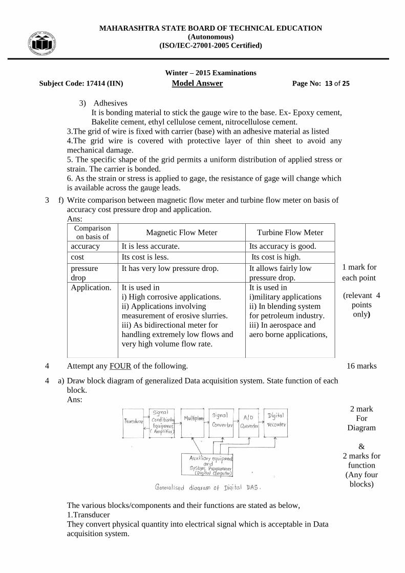
3 f) Write comparison between magnetic flow meter and turbine flow meter on basis of
accuracy cost pressure drop and application.
Ans: Comparison
on basis of Magnetic Flow Meter Turbine Flow Meter
accuracy It is less accurate. Its accuracy is good.
cost Its cost is less. Its cost is high.
pressure
drop
It has very low pressure drop. It allows fairly low
pressure drop.
Application. It is used in
i) High corrosive applications.
ii) Applications involving
measurement of erosive slurries.
iii) As bidirectional meter for
handling extremely low flows and
very high volume flow rate.
It is used in
i)military applications
ii) In blending system
for petroleum industry.
iii) In aerospace and
aero borne applications,
1 mark for
each point
(relevant 4
points
only)
4 Attempt any FOUR of the following. 16 marks
4 a) Draw block diagram of generalized Data acquisition system. State function of each
block.
Ans:
The various blocks/components and their functions are stated as below,
1.Transducer
They convert physical quantity into electrical signal which is acceptable in Data
acquisition system.
2 mark
For
Diagram
&
2 marks for
function
(Any four
blocks)

MAHARASHTRA STATE BOARD OF TECHNICAL EDUCATION
(Autonomous)
(ISO/IEC-27001-2005 Certified)
Winter – 2015 Examinations
Subject Code: 17414 (IIN) Model Answer Page No: 14 of 25
2.Signal Conditioning equipment
It is necessary to perform certain operation like amplification, attenuation on signal
before it is transmitted to next stage in order to bring it in desired form acceptable
by it. This is called signal conditioning associated with the equipment.
3.Multiplexer
Multiplexing is the process of sharing a single channel with more than one input.
Multiplexer accept more than one analog inputs and connects them sequentially to
one measuring instrument .It is named as scanner.
4.signal Converter
It translates the analog signal to a form acceptable by analog to digital converter.
5. Analog to Digital Converter
An A/D converter converts the analog voltage to its equivalent digital form. The
output of A/D converter may be fed to digital display devices for visual display or
recorder.
6.Auxilliary equipment’s
This contains device for system programming functions and digital data processing.
Some of typical functions are linearization or limit comparison of signal. These
functions may be performed by individual device or digital computer.
7. Digital Recorder
Records the information in digital form with type written pages, floppy disk,
magnetic tape etc.
8. Digital Printer
After all test have been completed and data generated it is necessary to record the
number or in some cases reduce data in more significant form. Digital printer
provides a high quality hard copy of record.
4 b) Write stepwise procedure to carry out calibration.
Ans:
Steps to Calibrate Instruments:
1. Calibration procedure involves a comparison of particular instrument to be
calibrated with either primary or secondary standard or instrument of known
accuracy.
2. When transducer is calibrated it will acts as test instrument while meter and
generator acts as standard instrument.
3. When meter is calibrated it will acts as test instrument while source or generator
acts as standard instrument.
4. Deviation of test instrument (meter) from standard value is compared with
allowable performance limit.
5. If deviation is within allowable performance limit specified by accuracy or
1 mark
each step
(variations
allowed
with the
gist being
parallel to
given)

MAHARASHTRA STATE BOARD OF TECHNICAL EDUCATION
(Autonomous)
(ISO/IEC-27001-2005 Certified)
Winter – 2015 Examinations
Subject Code: 17414 (IIN) Model Answer Page No: 15 of 25
within tolerance of measurement.
6. If Deviation crosses the allowable performance limit then meter parameter is
adjusted to or some faulty components are replaced to remove error.
4 c) Draw the response of first order instrument to step input and explain it.
Ans:
The Response is shown in fig.
The T.F. of First order system is ,
V0 (s) = 1
Vi (s) 1 + sRC
For Unit Step input Vi(s) = 1
𝑠
So, V0 (s) = 1
s(1+sRC) =
A′
s +
B′
1+sRC
Where : A’ = 1 and B’ = - RC
Vo(s) = 1
s -
RC
1+sRC =
1
s -
1
s +
1
RC
Taking Laplace inverse,
Vo(t) = 1 – 𝑒−𝑡
𝑅𝐶 => Css + ct(t)
Css = 1 and ct(t) = – e−t
RC
The response is purely exponential
2 marks for
correct
response
1 Mark for
TF
1 M for
ILT

MAHARASHTRA STATE BOARD OF TECHNICAL EDUCATION
(Autonomous)
(ISO/IEC-27001-2005 Certified)
Winter – 2015 Examinations
Subject Code: 17414 (IIN) Model Answer Page No: 16 of 25
4 d) Define Transducer and Give classification of transducer with one example each.
Ans:
Transducer is the device which converts one form of energy into another.
Transducers are classified as
A] Based on Physical Phenomenon
i) Primary transducer. Ex- Bourdon tube
ii) Secondary transducer Ex-LVDT
B] Based on Power type classification
i) Active transducer Ex- Piezoelectric Crystal, Thermocouple etc.
ii) passive transducer Ex-Thermistors, strain Gauges
C] Based on type of output
i)Analog transducer Ex- Strain Gauges, Potentiometers
ii) Digital transducers Ex- Rotary Encoder
D] Based on Transduction phenomenon
i) Transducer (Electrical) Ex-Thermistor
ii) Inverse Transducer(Mechanical) Ex- Bourdon Tube, Bellows
Def.1 mark
&
Any three
based
classificatio
n with one
example
(1 mark
each)
4 e) Define the following term related to OP-AMP i) Supply voltage rejection ratio ii)
Output voltage swing iii) Input offset voltage iv) Input bias current
Ans:
Supply voltage rejection ratio (SVRR)
It is the ratio of change in input offset voltage (Vio) of the op-amp caused due to
change in power supply voltage.
Output voltage swing (Vomax)
It is the maximum peak to peak output voltage that can be obtained without the
waveform getting clipped or distorted.
Input offset voltage(Vio)
It is the difference of voltage that must be applied between the two input terminals
of an op-amp to null the output.
Input bias current (IB)
It is the average current flowing into the inverting and noninverting input terminals
of op-amp.
1 mark for
each
correct
Definition
4 f) Give the comparison between thermistor and RTD. (Any four points)
Ans:
Thermistor RTD
Made of metallic oxides such as
cobalt, manganese, nickel etc.
Made of metals which are
good conductors of electricity

MAHARASHTRA STATE BOARD OF TECHNICAL EDUCATION
(Autonomous)
(ISO/IEC-27001-2005 Certified)
Winter – 2015 Examinations
Subject Code: 17414 (IIN) Model Answer Page No: 17 of 25
e.g. copper, platinum Nickel
PTC and NTC both types are
available
Have Positive temperature
coefficient of resistance.
Temperature range:
-50 C to 300 C
Temperature range:
-100 C to 650 C
It has nonlinear temperature versus
resistance curve.
It has linear temperature versus
resistance curve.
As made of metal oxide they are
less time stable
As made of metal they are
more stable
They have less reproducibility and
more hysteresis.
They have better
reproducibility and low
hysteresis.
Thermistor are quite small in size Relatively bigger in size
1 mark for
each point
(relevant 4
points
only)
5 Attempt any FOUR of the following: 16
5 a) Draw and explain pressure measurement using diaphragm type transducer.
Ans:
A diaphragm type pressure transducer is used
for low pressure measurement. They are
commercially available in two types: Metallic
and Non-metallic.
Working:
The diagram of diaphragm pressure gauge is
shown in the figure. When a force acts against a
thin stretched diaphragm, it causes a deflection
of the diaphragm with its center deflecting the
most.
If the pointer or mechanical movement is
connected to the LVDT or other secondary
transducer then it converts mechanical action
into electrical output.
2 marks for
figure
+
2 marks for
explanation
=
4 marks
5 b) Explain construction and working principle of photo electric type non-contact
tachometer with diagram.
Ans:
Photo electric type non-contact tachometer:
Principle: The light passes through the holes available on the rotating disc with a
1 mark for
any one
figure
MAHARASHTRA STATE BOARD OF TECHNICAL EDUCATION
(Autonomous)
(ISO/IEC-27001-2005 Certified)
Winter – 2015 Examinations
Subject Code: 17414 (IIN) Model Answer Page No: 18 of 25
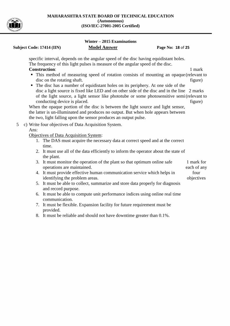
specific interval, depends on the angular speed of the disc having equidistant holes.
The frequency of this light pulses is measure of the angular speed of the disc.
Construction:
This method of measuring speed of rotation consists of mounting an opaque
disc on the rotating shaft.
The disc has a number of equidistant holes on its periphery. At one side of the
disc a light source is fixed like LED and on other side of the disc and in the line
of the light source, a light sensor like phototube or some photosensitive semi
conducting device is placed.
When the opaque portion of the disc is between the light source and light sensor,
the latter is un-illuminated and produces no output. But when hole appears between
the two, light falling upon the sensor produces an output pulse.
1 mark
(relevant to
figure)
2 marks
(relevant to
figure)
5 c) Write four objectives of Data Acquisition System.
Ans:
Objectives of Data Acquisition System:
1. The DAS must acquire the necessary data at correct speed and at the correct
time.
2. It must use all of the data efficiently to inform the operator about the state of
the plant.
3. It must monitor the operation of the plant so that optimum online safe
operations are maintained.
4. It must provide effective human communication service which helps in
identifying the problem areas.
5. It must be able to collect, summarize and store data properly for diagnosis
and record purpose.
6. It must be able to compute unit performance indices using online real time
communication.
7. It must be flexible. Expansion facility for future requirement must be
provided.
8. It must be reliable and should not have downtime greater than 0.1%.
1 mark for
each of any
four
objectives

MAHARASHTRA STATE BOARD OF TECHNICAL EDUCATION
(Autonomous)
(ISO/IEC-27001-2005 Certified)
Winter – 2015 Examinations
Subject Code: 17414 (IIN) Model Answer Page No: 19 of 25
5 d) Draw and explain circuit diagram of phase detector.
Ans:
Phase Detector:
Phase detector compares the input
frequency and the VCO frequency and
generates a DC voltage i.e. proportional
to the phase difference between two
frequencies. X-OR type of phase
detector is generally used if the fin and
fout are square waves. X-OR type of
phase detector uses X-OR gate such as
CMOS type 4070. The output of X-OR
gate is high only when Fin or Fout is high.
Fin is leading Fout by Φ degrees. The DC
output voltage of X-OR phase detector
is a function of the phase difference
between its two inputs.
This graph indicates that maximum DC
output voltage occurs when phase
difference is π radians or 180⁰. The slope of curve between 0 & π radians is the
conversion gain Kp of the phase detector which is given by
𝐾𝑝 =𝑉𝑐𝑐
π
[Note: explanation of any other detector such as edge triggered or monolithic
phase detector should be considered]

MAHARASHTRA STATE BOARD OF TECHNICAL EDUCATION
(Autonomous)
(ISO/IEC-27001-2005 Certified)
Winter – 2015 Examinations
Subject Code: 17414 (IIN) Model Answer Page No: 20 of 25
5 e) Explain with diagram liquid level measurement using ultrasonic method.
Ans:
Ultrasonic level sensors work on the “time of
flight” principle using the speed of sound. The
sensor emits a high-frequency pulse, generally in
the 20 kHz to 200 kHz range and then listens for
the echo. The pulse is transmitted in a cone,
usually about 6 at the apex. The pulse impacts
the level surface and is reflected back to the
sensor, now acting as a receiver and then to the
transmitter for signal processing.
Basically, the transmitter divides the time
between the pulse and its echo by two, and that
is the distance to the surface of the material. The
transmitter is designed to listen the highest
amplitude return pulse (the echo) and mask out
all the other ultrasonic signals in the vessel.
1 mark for
diagram
3 marks for
explanation
5 f) Draw the neat sketch of the diaphragm. Explain its construction and working.
Ans:
Diaphragm:
The diaphragm is flexible disc, either flat or with concentric corrugation, which is
made from sheet metal of precise dimensions, mainly divided into
i) Corrugated single diaphragm
ii) Capsule diaphragm
The pressure deflection characteristics of both flat and corrugated diaphragms have
been well investigated.
When the pressure is applied on
the diaphragm, it is elongated
due to the property of elasticity
and we can measure the
pressure.
2 marks for
sketch
1 mark for
constructio
n
1 mark for
working
6 Attempt any FOUR of the following: 16
6 a) Define torque. Explain measurement of torque using torque cell.
Ans:
Torque:
Torque is defined as that force which tends to produce rotation. Specially, it is the
moment due to tangential force.
T = L W, where T is the torque, L is the length of the force arm and W is the force.
The in-line rotating sensor for larger torques consists of a metal shaft with bonded
strain gauges (or load cell) electrically connected
in the form of a Wheatstone bridge. Figure
illustrates the stresses acting on a rotating shaft
subjected to torsion.
The strain gauges are kept on the shaft at
1 mark
1 mark for
figure
2 marks for
explanation

MAHARASHTRA STATE BOARD OF TECHNICAL EDUCATION
(Autonomous)
(ISO/IEC-27001-2005 Certified)
Winter – 2015 Examinations
Subject Code: 17414 (IIN) Model Answer Page No: 21 of 25
precisely 45 to the shaft axis to sense compressive and tensile deformation due to
torsion. The Wheatstone bridge output is proportional to torsion and hence the
torque.
6 b) Define stress and strain. List types of strain gauges.
Ans:
Strain:
It is the relative change in shape or size of an object due to externally applied force.
𝑠𝑡𝑟𝑎𝑖𝑛 =𝑒𝑥𝑡𝑒𝑛𝑠𝑖𝑜𝑛 (𝑐ℎ𝑎𝑛𝑔𝑒 𝑖𝑛 𝑙𝑒𝑛𝑔𝑡ℎ)
𝑜𝑟𝑖𝑔𝑖𝑛𝑎𝑙 𝑙𝑒𝑛𝑔𝑡ℎ
𝜀 =∆𝐿
𝐿
Stress:
It is defined as the force per unit area of a material.
i.e. 𝑠𝑡𝑟𝑒𝑠𝑠 =𝐹𝑜𝑟𝑐𝑒
𝐶𝑟𝑜𝑠𝑠−𝑠𝑒𝑐𝑡𝑖𝑜𝑛𝑎𝑙 𝐴𝑟𝑒𝑎=
𝐹
𝐴
𝜎 =𝐹
𝐴
Types of Strain Gauges:
i) Metallic strain gauge
a) Unbonded metallic strain gauge
b) Bonded metallic strain gauge
ii) Semiconductor type strain gauge
1 mark
1 mark
1 mark for
each of two
types
6 c) Draw and explain ratio metric conversion. Ans:
The measurement of a voltage is actually being used to measure another quantity
such as resistance. In such instances, the measurement can be set up to read the
resistance more directly as a ratio to a reference resistor. By putting the same
current through both the sensor resistance and the reference resistor, the ADC result
will be a measure of the ratio of the two resistors.
As one can see, the accuracy of the measurement is now set with the reference
resistor. The current is no longer critical to the accuracy of the measurement. All
that is required is that the current does not change during the conversion, or over-
2 marks for
relevant
explanation
1 mark for
each
diagram

MAHARASHTRA STATE BOARD OF TECHNICAL EDUCATION
(Autonomous)
(ISO/IEC-27001-2005 Certified)
Winter – 2015 Examinations
Subject Code: 17414 (IIN) Model Answer Page No: 22 of 25
range either the reference or analog inputs of the ADC. Since it is much easier (and
cheaper) to purchase high precision resistors than voltage references, the accuracy
can be set to a higher level.
An example ratio-metric circuit using a resistance temperature detector (RTD).
Here RTD is considered as example but any other resistive transducer can be
considered as an example like strain gauge etc.
OR 1. Different configurations for ratio metric measurement are shown below.
2. The multiplier operates by converting the two input voltages to be
multiplied into currents and generating an output current which is the ratio
of the product of the two input currents to reference current.
3. The multiplier can be used as modulators and demodulators as gain control
elements and in power measurements.
4. The multiplier can also be used to provide division and square rooting.
5. The divider uses the multiplier in a feedback configuration.
6. Division enables fixed and variable gain elements to be constructed and
ratio metric measurement to be made.
MAHARASHTRA STATE BOARD OF TECHNICAL EDUCATION
(Autonomous)
(ISO/IEC-27001-2005 Certified)
Winter – 2015 Examinations
Subject Code: 17414 (IIN) Model Answer Page No: 23 of 25
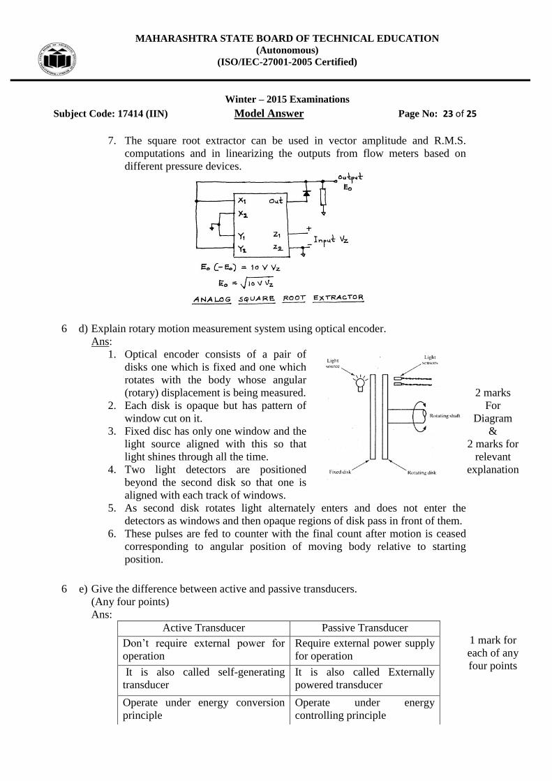
7. The square root extractor can be used in vector amplitude and R.M.S.
computations and in linearizing the outputs from flow meters based on
different pressure devices.
6 d) Explain rotary motion measurement system using optical encoder.
Ans:
1. Optical encoder consists of a pair of
disks one which is fixed and one which
rotates with the body whose angular
(rotary) displacement is being measured.
2. Each disk is opaque but has pattern of
window cut on it.
3. Fixed disc has only one window and the
light source aligned with this so that
light shines through all the time.
4. Two light detectors are positioned
beyond the second disk so that one is
aligned with each track of windows.
5. As second disk rotates light alternately enters and does not enter the
detectors as windows and then opaque regions of disk pass in front of them.
6. These pulses are fed to counter with the final count after motion is ceased
corresponding to angular position of moving body relative to starting
position.
2 marks
For
Diagram
&
2 marks for
relevant
explanation
6 e) Give the difference between active and passive transducers.
(Any four points)
Ans:
Active Transducer Passive Transducer
Don’t require external power for
operation
Require external power supply
for operation
It is also called self-generating
transducer
It is also called Externally
powered transducer
Operate under energy conversion
principle
Operate under energy
controlling principle
1 mark for
each of any
four points

MAHARASHTRA STATE BOARD OF TECHNICAL EDUCATION
(Autonomous)
(ISO/IEC-27001-2005 Certified)
Winter – 2015 Examinations
Subject Code: 17414 (IIN) Model Answer Page No: 24 of 25
Circuit is simple Circuit is complex
Active bridge is not required Active bridge is required
Ex-Thermocouple, piezoelectric Ex Thermistor, Strain Gauges
6 f) Explain AC Current RMS indication using Hall effect transducer.
Ans:
Measurement of current using Hall effect transducer:
It serves to measure current in
conductor without the need for
interrupting the circuit and
without making electrical
connection between the
conductor circuit and meter. A
current (dc or ac) passes through
the conductor and sets up
magnetic field around the
conductor. The magnetic field is
proportional to current. A hall
effect transducer is placed in
slotted ferromagnetic tube which acts as magnetic concentrator. The voltage
produced at the output terminals is proportional to the magnetic field strength hence
proportional to current flowing in the conductor
OR
1. As shown in fig an iron core of suitable dimensions as per design is
constructed.
2. A small cut is made or the slot is made on one of its limbs to place the Hall
Effect sensor.
3. The conductor carries a.c current which is to be measured. This conductor is
placed in the core as shown in fig.
4. Iac produces magnetic flux (ɸac) in the core.
5. This flux passes through the core and the air gap in which the Hall Effect
sensor is placed.
6. The Hall Effect sensor produces output VH which is proportional to the flux
density in the air gap.
7. The flux density is produced due to Iac, hence VH α B α Iac.
8. So we can measure Iac in term of VH.
9. The output voltage VH is amplified using amplifier circuit.
10. In signal conditioning the scaling of signal is done such that display shows
the value of Iac directly.
2 marks for
diagram
2 marks for
relevant
explanation

MAHARASHTRA STATE BOARD OF TECHNICAL EDUCATION
(Autonomous)
(ISO/IEC-27001-2005 Certified)
Winter – 2015 Examinations
Subject Code: 17414 (IIN) Model Answer Page No: 25 of 25