maintenance and repair manual - uab jupojos technika asys/saf/literatura_servisams... ·...
TRANSCRIPT
SK RS 9042 - SK 500 plus
Maintenance and Repair Manual
Service
Edition 01/2006
2
Vehicle information
Manufacturer.................................................................................................................................
Address...........................................................................................................................................
Body type.......................................................................................................................................
Chassis no.......................................................................................................................................
Year of manufacture ....................................................................................................................
Registration, date-in-service.........................................................................................................
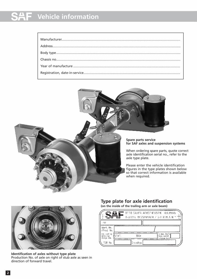
Identification of axles without type plateProduction No. of axle on right of stub axle as seen in direction of forward travel.
Type plate for axle identification(on the inside of the trailing arm or axle beam)
Spare parts servicefor SAF axles and suspension systems
When ordering spare parts, quote correctaxle identification serial no., refer to theaxle type plate.
Please enter the vehicle identification figures in the type plates shown below so that correct information is availablewhen required.
96195
047
Spare part illustration and spare part designationSK RS 9042 - SK 500 plus 10-11
SAF axle identification 2
Repairing the brakes 12-22
Repairing the wheel bearingsReplacing the wheel bearing grease 23-25
E) Installation instructions
D) Spare part illustrations/spare part designation
C) Maintenance instructions
Maintenance instructions for SK RS 9042 - SK 500 plus 8
Maintenance schedule for SK RS 9042 - SK 500 plus 9
3
Contents
Page
This manual is intended for the technical workshop personnel responsible for maintenance and repair.
A) Component description 4-6
B) General service instructions for SAF axles and suspension units 7
Adjustment of S-cam brakes with manual slack adjusters 26
Adjustment of HALDEX automatic slack adjusters 27
Adjustment of S-ABA automatic slack adjusters 28
F) Slack adjuster
G) Track control 29-30
H) Service tools 31-32
I) Tightening torque in Nm 33
The item numbers indicated are given only for identification and to distinguish between different versions.
Use the part numbers from the valid spare parts documents for identification of spare parts.
SAF axles and suspension units are subject to continuous further development; the data and drawings contained in the manual may therefore differ from the details given in the operating permit.
The contents of the manual does not constitute the basis for a legal claim.
Reprinting, reproduction or translation in whole or in part is not permitted.
The issue of this publication invalidates all earlier maintenance and repair manuals.
4
A) Component Description
The components of the SAF axle Types SK 500 plus have important technical details which distinguish themfrom other axle types:
– Great ease of installation(e.g. only 1/4 of the working time is now required for brake repairs)
– Long wheel bearing grease change intervals of 500,000 km or 60 months’ operation
– Favourable lubrication intervals for the camshaft bearing at each brake lining change, but not later thanevery 12 months
– Approx. 40% less individual components in the brakes
– Wheel bearing clearance adjustment is required as in the past
Overview of the Components
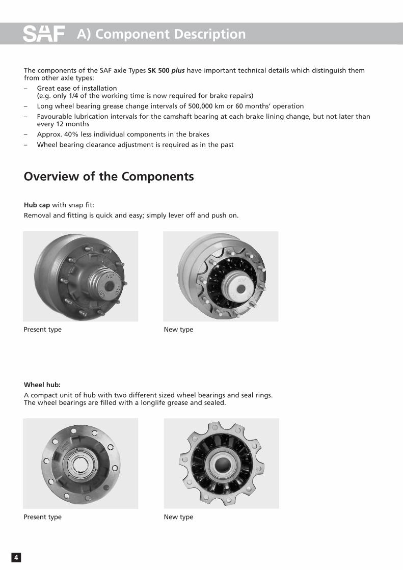
Hub cap with snap fit:
Removal and fitting is quick and easy; simply lever off and push on.
New typePresent type
New typePresent type
Wheel hub:
A compact unit of hub with two different sized wheel bearings and seal rings. The wheel bearings are filled with a longlife grease and sealed.
5
A) Component Description
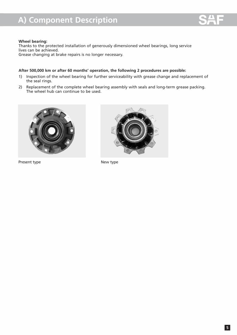
Wheel bearing:Thanks to the protected installation of generously dimensioned wheel bearings, long service lives can be achieved. Grease changing at brake repairs is no longer necessary.
After 500,000 km or after 60 months’ operation, the following 2 procedures are possible:
1) Inspection of the wheel bearing for further serviceability with grease change and replacement of the seal rings.
2) Replacement of the complete wheel bearing assembly with seals and long-term grease packing. The wheel hub can continue to be used.
New typePresent type

6
A) Component Description
Wheel bearing clearanceThe wheel bearing clearance has to be adjusted as in the past.
Axle nutsThe axle nuts have a right-hand thread on both sides. The wheelhub is secured with a lock nut.
Brake shoesThe brake shoes are each supported spherically on a ball and areheld by a spring clamp. Only one return spring is required for thereturn of the brake shoes. The brake shoe cam rollers are guidedexactly in the specially machined S-cam profile.
Brake liningsTwo different asymmetrically formed lining segments are rivetedonto the brake shoes. The thicker end of the lining is installed onthe S-cam side (cam roller).
As a result of this scythe-shaped brake lining contour, uniform maxi-mum wear of the brake lining over the whole surface is achievedduring normal operation.
The brake linings have an embossed groove on the end surfaceswhich indicates the maximum permissible lining wear.
CamshaftThe camshafts are mounted in the brake carrier and in the slack adjuster in a compact bearing which allows quick replacement. Bothbearings have grease nipples and must be regresed every 12 months.
Both bearings have a long-life lubrication and are protected by sealrings and rubber sleeves against the ingress of dirt and splash water.
On the slack adjuster end the camshaft has a milled groove and a slip-on indicator for visual checking of the brake lining wear.
When the wear indicators have reached a horizontal position, an inspection of the brake lining thickness must be carried out.
Max. permitted radial play: 2 mm
Inspection of the brake lining thicknessDuring maintenance work, the thickness of the brake linings can be inspected at two sight holes in the rear cover plate.
7
B) General service instructions
Please observe the following safety instructions in order to maintain the operational and road safety of your SAF axles and suspension systems:
1. The wheel contact surfaces between the wheel disc and wheel hub and the wheel nut contact surface at the wheel disc must not be additionally painted. The contact surfaces must be clean, smooth and free from grease. Failure to observe this may result in the wheel coming loose. Any additional instructions of the wheel manufacturer must also be observed.
2. Only the wheel and tyre sizes approved by the trailer builder may be used. The tyres must always have the specified inflation pressure.
3. The brake systems of the tractor and the trailer/semi-trailer must be synchronised by means of a tractor/trailer brake synchronisation not later than 5,000 km after the initial start of operation of the trailer/semi-trailer in order to ensure a safe and uniform braking behaviour and uniform brake pad wear.Tractor/trailer brake synchronisations should be carried out by appropriately qualified and equipped brake workshops.
The use of an additional braking system, such as a trailer anti-jackknife brake is forbidden by law on vehicles with type approval after January 1999.
4. Before starting a journey, ensure that the maximum permissible axle load is not exceeded and that the load is distributed equally and uniformly.
5. On trailers with air suspension, ensure that the air bags are completely filled with air before starting the journey. Incompletely filled air bags may result in damage to axles, suspension, frame and superstructureand impair road safety.
6. Ensure that the brakes are not overheated by continuous operation.
With drum brakes, overheating can result in a hazardous deterioration in the braking efficiency.
With disc brakes, overheating can result in damage to surrounding components – in particular the wheel bearings. This can result in a significant deterioration in road safety, e.g. failure of wheel bearings.
7. The parking brake must not be immediately applied when the brakes are hot, as the brake discs and brake drums may be damaged by different stress fields during cooling.
8. Use the supports provided when loading and unloading in order to avoid damage to the axle.
9. Observe the operating recommendation of the trailer builder for off-road operation of the installed axles and suspension systems.
The SAF definition of OFF-ROAD means driving on non-asphalted / non-concreted routes, such as e.g. gravel roads, agricultural and forestry tracks, on construction sites and in gravel pits.
Off-road operation of SAF axles and suspension systems not designed for the purpose may result in damage and hence to an impairment of road safety.
10. SAF axles and suspension systems require continuous care, service and maintenance in order to maintain operational and road safety and to be able to recognise natural wear and defects in good time.
The daily inspection of the trailer for road safety before starting the journey is one of the driver’s obligations.
SAF recommends that at least the inspections and maintenance operations described on page 8 should be carried out.
We recommend the use of original SAF spare parts.
A close-knit service network of SAF partner companies is available for the technical support of the SAF axlesand suspension systems and for the supply of original SAF spare parts (see rear cover or on the Internet under www.saf-axles.com).
Updates will be published as necessary on the Internet under www.saf-axles.com.
8
C) Maintenance instructions
SK RS 9042 - SK 500 plus
Vehicles with long standing periods: service at specified time intervalsVehicles used under extreme conditions: service at suitably reduced intervals
Maintenance intervals
whichever comes first
Mileage intervals >
Time intervals >
After first5,000 km
orevery
30,000 kmevery
150,000 km
After firstmonth
every3 months
every75,000 km
every6 months
every12 months
Periodic checks
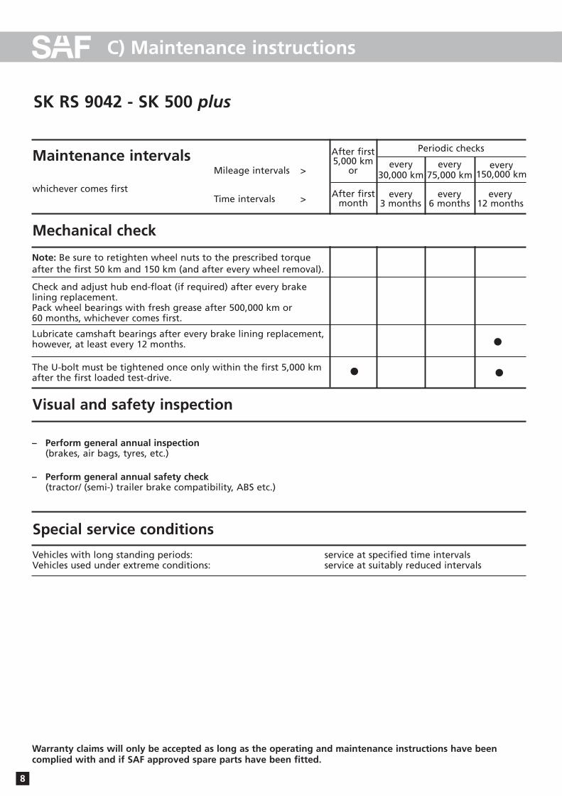
Check and adjust hub end-float (if required) after every brake lining replacement.Pack wheel bearings with fresh grease after 500,000 km or 60 months, whichever comes first.
Lubricate camshaft bearings after every brake lining replacement,however, at least every 12 months.
The U-bolt must be tightened once only within the first 5,000 km after the first loaded test-drive.
– Perform general annual inspection(brakes, air bags, tyres, etc.)
– Perform general annual safety check(tractor/ (semi-) trailer brake compatibility, ABS etc.)
Note: Be sure to retighten wheel nuts to the prescribed torque after the first 50 km and 150 km (and after every wheel removal).
Mechanical check
Visual and safety inspection
Special service conditions
• ••
Warranty claims will only be accepted as long as the operating and maintenance instructions have been complied with and if SAF approved spare parts have been fitted.
9
C) Maintenance instructions
SK RS 9042 - SK 500 plus
Adjusting the wheel bearing clearance:
Tighten axle nut W.A.F. 85 (22) to a torque of 150 Nm, turning the wheel hub at the same time.
Back off the axle nut by 2 1/2 holes of the locking collar(23).
Push on the locking collar and secure the hub nut withdowel.
Tighten the lock nut (24) to a torque of 400 Nm.
Check that the wheel bearing rotates freely and withoutexcessive end float. The wheel must rotate freely and with-out resistance and no end float should be felt at the wheelrim. Repeat the adjustment, if necessary.
Lubricant specification:
Wheel bearings:SAF Part No. 4 387 0011 05
Camshaft:SAF Part No. 4 387 0011 05
Stub axle:SAF Part No. 4 387 0015 06SAF fitting paste
Brake anchor bracket ball:SAF Part No. 4 387 0007 00 Copper paste
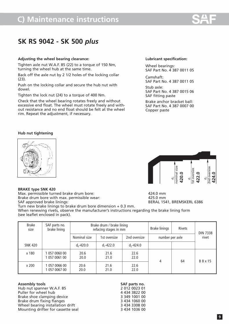
Hub nut tightening
Assembly tools SAF parts no.Hub nut spanner W.A.F. 85 2 012 0023 01Puller for wheel hub 4 434 3822 00Brake shoe clamping device 3 349 1001 00Brake drum fixing flanges 3 434 1060 00Wheel bearing installation drift 3 434 3308 00Mounting drifter for cassette seal 3 434 1036 00
Brake drum / brake liningrefacing stages in mm
BRAKE type SNK 420Max. permissible turned brake drum bore: 424.0 mmBrake drum bore with max. permissible wear: 425.0 mmSAF approved brake linings: BERAL 1541, BREMSKERL 6386Turn new brake linings to brake drum bore dimension + 0.3 mm.When renewing rivets, observe the manufacturer’s instructions regarding the brake lining form (see leaflet enclosed in pack).
Nor
mal
maß
1. R
ep.-
Stu
fe
2. R
ep.-
Stu
fe
d 0
d 1 d 2
Brake linings Rivets
420.
0
422.
0
424.
0
DIN 7338rivetnumber per axle
SNK 420 d0-420.0 d1-422.0 d2-424.0
x 180 1 057 0060 00 20.6 21.6 22.61 057 0061 00 20.0 21.0 22.0
x 200 1 057 0066 00 20.6 21.6 22.61 057 0067 00 20.0 21.0 22.0
64 B 8 x 15
Nominal size 1st oversize 2nd oversize
Brake SAF parts no.size brake lining
4
no
min
al s
ize
1st
ove
rsiz
e
2nd
ove
rsiz
e
10
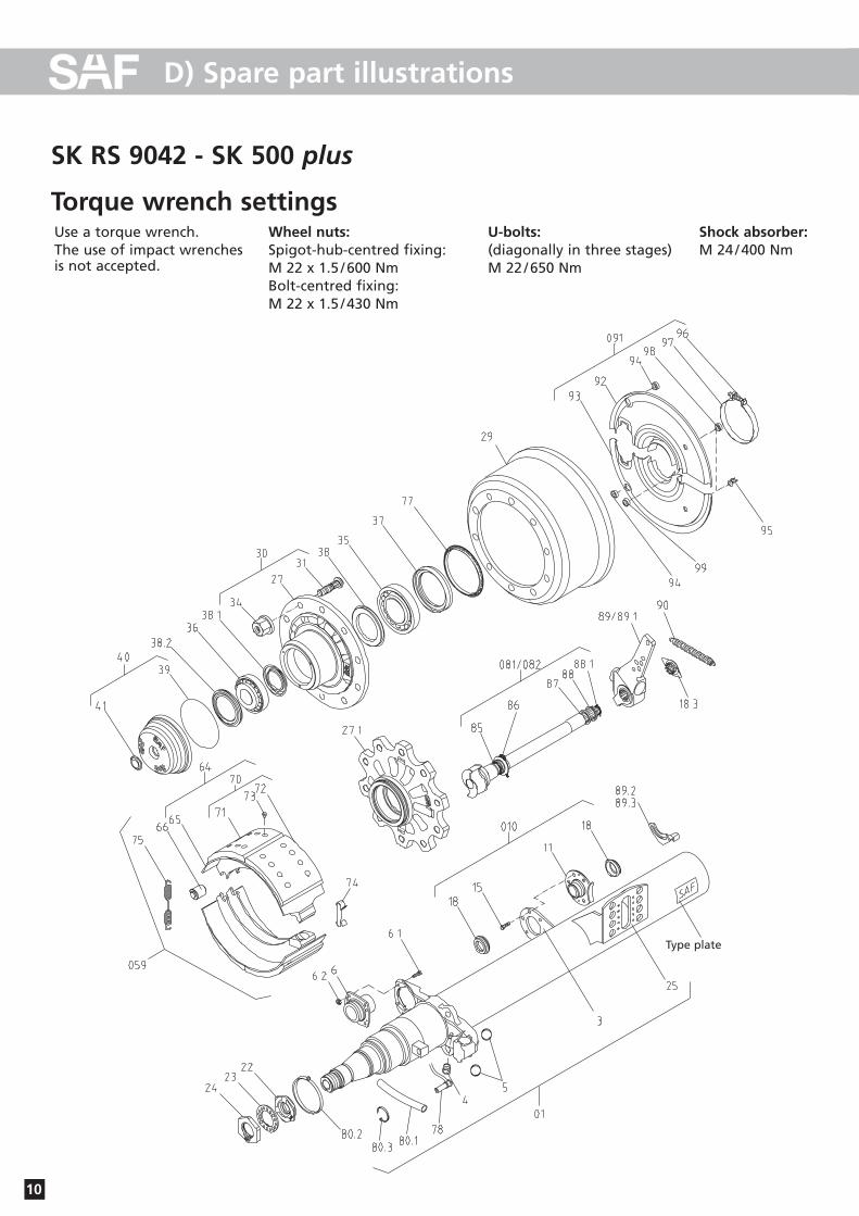
D) Spare part illustrations
SK RS 9042 - SK 500 plus
Torque wrench settingsUse a torque wrench.The use of impact wrenches is not accepted.
Wheel nuts:Spigot-hub-centred fixing:M 22 x 1.5 /600 NmBolt-centred fixing:M 22 x 1.5 /430 Nm
U-bolts:(diagonally in three stages)M 22 /650 Nm
Shock absorber:M 24 /400 Nm
Type plate
11
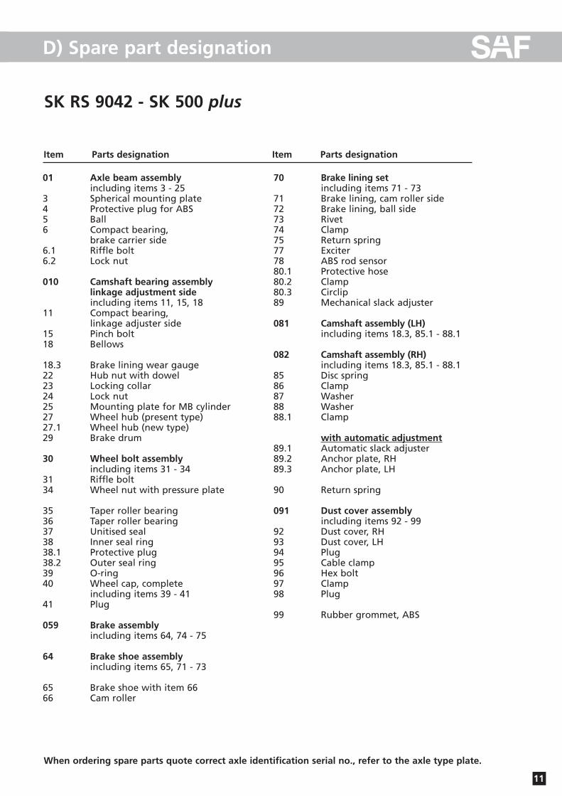
D) Spare part designation
SK RS 9042 - SK 500 plus
Item Parts designation Item Parts designation
01 Axle beam assemblyincluding items 3 - 25
3 Spherical mounting plate4 Protective plug for ABS5 Ball 6 Compact bearing,
brake carrier side6.1 Riffle bolt6.2 Lock nut
010 Camshaft bearing assemblylinkage adjustment sideincluding items 11, 15, 18
11 Compact bearing, linkage adjuster side
15 Pinch bolt18 Bellows
18.3 Brake lining wear gauge22 Hub nut with dowel23 Locking collar24 Lock nut25 Mounting plate for MB cylinder27 Wheel hub (present type)27.1 Wheel hub (new type)29 Brake drum
30 Wheel bolt assemblyincluding items 31 - 34
31 Riffle bolt34 Wheel nut with pressure plate
35 Taper roller bearing36 Taper roller bearing37 Unitised seal38 Inner seal ring38.1 Protective plug38.2 Outer seal ring39 O-ring40 Wheel cap, complete
including items 39 - 4141 Plug
059 Brake assemblyincluding items 64, 74 - 75
64 Brake shoe assemblyincluding items 65, 71 - 73
65 Brake shoe with item 6666 Cam roller
70 Brake lining set including items 71 - 73
71 Brake lining, cam roller side72 Brake lining, ball side73 Rivet74 Clamp75 Return spring77 Exciter78 ABS rod sensor80.1 Protective hose80.2 Clamp80.3 Circlip89 Mechanical slack adjuster
081 Camshaft assembly (LH) including items 18.3, 85.1 - 88.1
082 Camshaft assembly (RH) including items 18.3, 85.1 - 88.1
85 Disc spring86 Clamp87 Washer88 Washer88.1 Clamp
with automatic adjustment89.1 Automatic slack adjuster89.2 Anchor plate, RH89.3 Anchor plate, LH
90 Return spring
091 Dust cover assemblyincluding items 92 - 99
92 Dust cover, RH93 Dust cover, LH94 Plug95 Cable clamp96 Hex bolt97 Clamp98 Plug
99 Rubber grommet, ABS
When ordering spare parts quote correct axle identification serial no., refer to the axle type plate.
12
E) Installation instructions
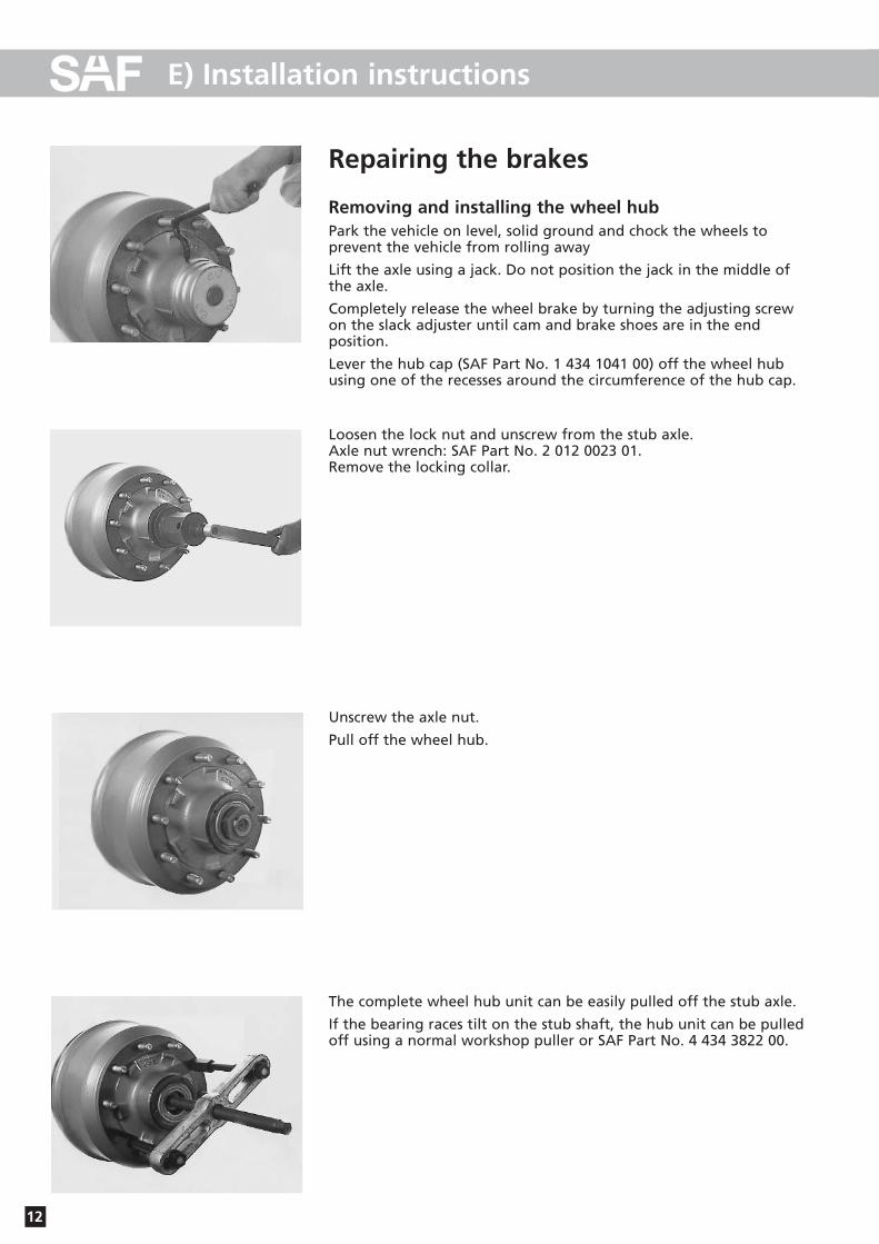
Repairing the brakes
Removing and installing the wheel hubPark the vehicle on level, solid ground and chock the wheels to prevent the vehicle from rolling away
Lift the axle using a jack. Do not position the jack in the middle ofthe axle.
Completely release the wheel brake by turning the adjusting screwon the slack adjuster until cam and brake shoes are in the end position.
Lever the hub cap (SAF Part No. 1 434 1041 00) off the wheel hubusing one of the recesses around the circumference of the hub cap.
Loosen the lock nut and unscrew from the stub axle. Axle nut wrench: SAF Part No. 2 012 0023 01.Remove the locking collar.
Unscrew the axle nut.
Pull off the wheel hub.
The complete wheel hub unit can be easily pulled off the stub axle.
If the bearing races tilt on the stub shaft, the hub unit can be pulledoff using a normal workshop puller or SAF Part No. 4 434 3822 00.
13
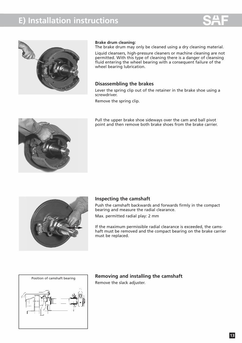
E) Installation instructions
Brake drum cleaning:The brake drum may only be cleaned using a dry cleaning material.
Liquid cleansers, high-pressure cleaners or machine cleaning are notpermitted. With this type of cleaning there is a danger of cleansingfluid entering the wheel bearing with a consequent failure of thewheel bearing lubrication.
Disassembling the brakesLever the spring clip out of the retainer in the brake shoe using a screwdriver.
Remove the spring clip.
Pull the upper brake shoe sideways over the cam and ball pivotpoint and then remove both brake shoes from the brake carrier.
Inspecting the camshaftPush the camshaft backwards and forwards firmly in the compactbearing and measure the radial clearance.
Max. permitted radial play: 2 mm
If the maximum permissible radial clearance is exceeded, the cams-haft must be removed and the compact bearing on the brake carriermust be replaced.
Removing and installing the camshaftRemove the slack adjuster.
Position of camshaft bearing

14
E) Installation instructions
Remove the spring clip fromthe groove in the camshaftand pull the camshaft com-pletely out of the bearing.
Arrangement and installationposition of the camshaft bearings, see drawing onpage 13.
Remove the bolts from the compact bearing and replace with a new bearings (see page 10, item 81 with parts 85.1 - 88.1, and item 10 with parts 11, 15 and 18).
After installation of th e newcompact bearing, the cams-haft must rotate freely. Insertthe bolts and fit the nuts.
Tightening torque for the bolts on the compact bearing:- Brake side 40 Nm - Slack adjuster side 35 Nm
15
E) Installation instructions
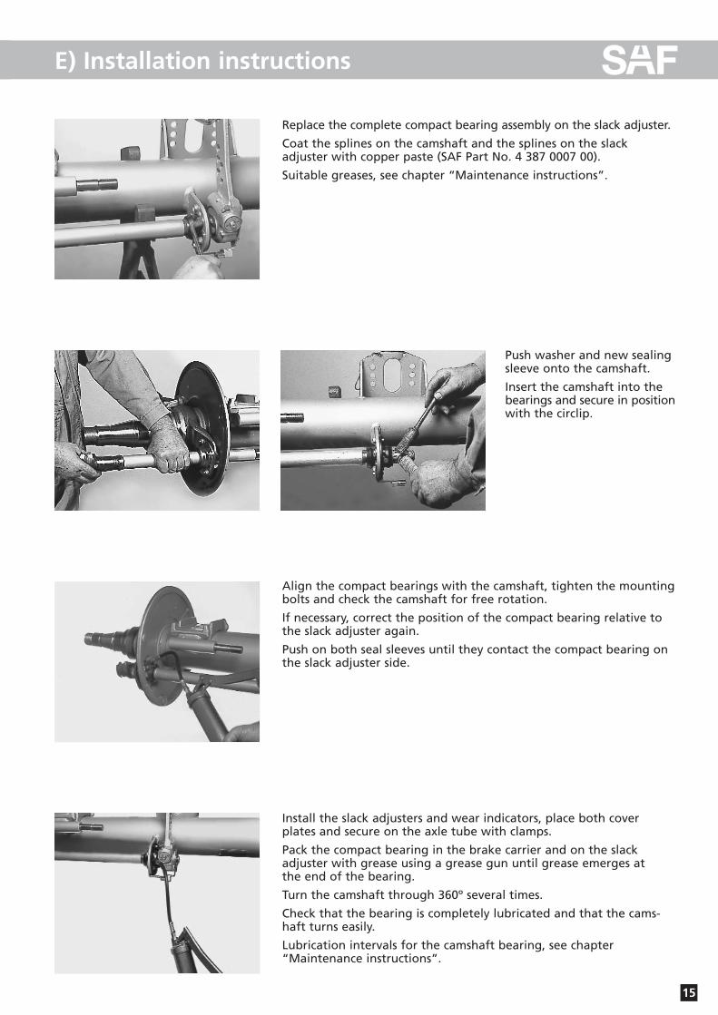
Replace the complete compact bearing assembly on the slack adjuster.
Coat the splines on the camshaft and the splines on the slack adjuster with copper paste (SAF Part No. 4 387 0007 00).
Suitable greases, see chapter “Maintenance instructions”.
Push washer and new sealingsleeve onto the camshaft.
Insert the camshaft into thebearings and secure in positionwith the circlip.
Align the compact bearings with the camshaft, tighten the mountingbolts and check the camshaft for free rotation.
If necessary, correct the position of the compact bearing relative tothe slack adjuster again.
Push on both seal sleeves until they contact the compact bearing onthe slack adjuster side.
Install the slack adjusters and wear indicators, place both cover plates and secure on the axle tube with clamps.
Pack the compact bearing in the brake carrier and on the slack adjuster with grease using a grease gun until grease emerges at the end of the bearing.
Turn the camshaft through 360º several times.
Check that the bearing is completely lubricated and that the cams-haft turns easily.
Lubrication intervals for the camshaft bearing, see chapter“Maintenance instructions”.

16
E) Installation instructions
Brake liningsOriginal dimensions and wear limits, see table in chapter“Maintenance instructions”.
Two different brake linings are riveted onto each brake shoe. The lining contour tapers towards the ball side.
The thicker end of the brake lining is riveted on the roller side (S-cam).
Corrosion-proofed steel rivets are used for securing the linings.
The brake linings have a monitoring shoulder on the face end indi-cating the brake lining type approved by SAF and the wear limit forthe minimum brake lining thickness.
Only brake linings of the same quality may be installed on the sameaxle.
Observe the approved rivet quality (see table in chapter“Maintenance”).
Replacement of the brake liningClean all parts and inspect for wear. Inspect the brake drum forwear and turn down to the next repair stage, if necessary (see tablein chapter “Maintenance instructions”).
Remove the brake lining from the brake shoe.
Thoroughly clean the mounting surface for the brake lining on thebrake shoe; grind slightly, if necessary.
Carefully remove any corrosion from the lining plate. Protect thecontact surface against corrosion with a thin coating of zinc dust primer.
Replace the brake linings according to the repair stage of the brakedrum (see table in chapter “Maintenance instructions”).
Observe the position of the different brake lining segments.
The thicker end of the brake lining is riveted on the roller side (S-cam).
17
E) Installation instructions
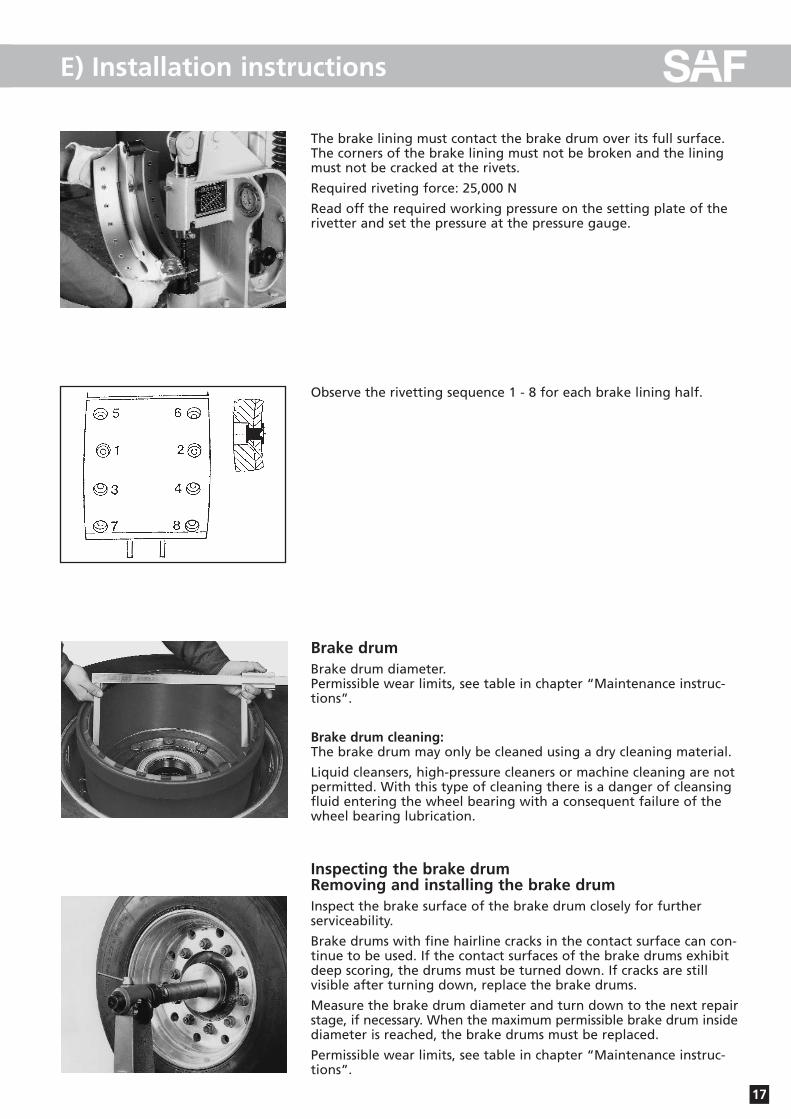
The brake lining must contact the brake drum over its full surface.The corners of the brake lining must not be broken and the liningmust not be cracked at the rivets.
Required riveting force: 25,000 N
Read off the required working pressure on the setting plate of therivetter and set the pressure at the pressure gauge.
Observe the rivetting sequence 1 - 8 for each brake lining half.
Brake drumBrake drum diameter.Permissible wear limits, see table in chapter “Maintenance instruc-tions”.
Brake drum cleaning:The brake drum may only be cleaned using a dry cleaning material.
Liquid cleansers, high-pressure cleaners or machine cleaning are notpermitted. With this type of cleaning there is a danger of cleansing fluid entering the wheel bearing with a consequent failure of thewheel bearing lubrication.
Inspecting the brake drumRemoving and installing the brake drumInspect the brake surface of the brake drum closely for further serviceability.
Brake drums with fine hairline cracks in the contact surface can con-tinue to be used. If the contact surfaces of the brake drums exhibitdeep scoring, the drums must be turned down. If cracks are still visible after turning down, replace the brake drums.
Measure the brake drum diameter and turn down to the next repairstage, if necessary. When the maximum permissible brake drum insidediameter is reached, the brake drums must be replaced.
Permissible wear limits, see table in chapter “Maintenance instruc-tions”.
18
E) Installation instructions
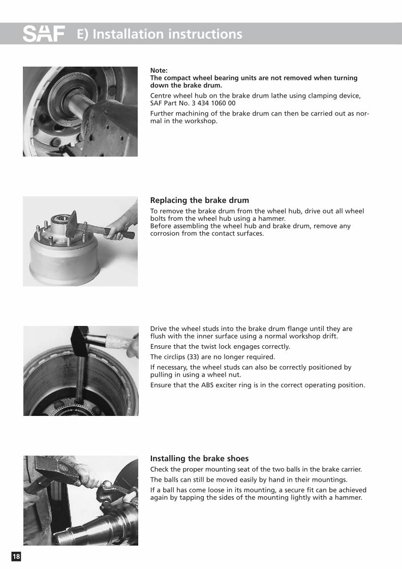
Note:The compact wheel bearing units are not removed when turningdown the brake drum.
Centre wheel hub on the brake drum lathe using clamping device,SAF Part No. 3 434 1060 00
Further machining of the brake drum can then be carried out as nor-mal in the workshop.
Replacing the brake drumTo remove the brake drum from the wheel hub, drive out all wheelbolts from the wheel hub using a hammer. Before assembling the wheel hub and brake drum, remove any corrosion from the contact surfaces.
Drive the wheel studs into the brake drum flange until they areflush with the inner surface using a normal workshop drift.
Ensure that the twist lock engages correctly.
The circlips (33) are no longer required.
If necessary, the wheel studs can also be correctly positioned by pulling in using a wheel nut.
Ensure that the ABS exciter ring is in the correct operating position.
Installing the brake shoesCheck the proper mounting seat of the two balls in the brake carrier.
The balls can still be moved easily by hand in their mountings.
If a ball has come loose in its mounting, a secure fit can be achievedagain by tapping the sides of the mounting lightly with a hammer.
19
E) Installation instructions
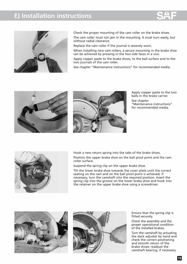
Check the proper mounting of the cam roller on the brake shoes.
The cam roller must not jam in the mounting. It must turn easily, butwithout radial clearance.
Replace the cam roller if the journal is severely worn.
When installing new cam rollers, a secure mounting in the brake shoecan be achieved by pressing in the two side faces in a vice.
Apply copper paste to the brake shoes, to the ball surface and to thetwo journals of the cam roller.
See chapter “Maintenance instructions” for recommended media.
Apply copper paste to the twoballs in the brake carrier.
See chapter “Maintenance instructions”for recommended media.
Hook a new return spring into the tabs of the brake shoes.
Position the upper brake shoe on the ball pivot point and the camroller surface.
Suspend the spring clip on the upper brake shoe.
Tilt the lower brake shoe towards the cover plate until the correctseating on the cam and on the ball pivot point is achieved; if necessary, turn the camshaft into the required position. Insert thespring clip into the groove on the lower brake shoe and hook intothe retainer on the upper brake shoe using a screwdriver.
Ensure that the spring clip is fitted securely.
Check the assembly and theproper operational conditionof the installed brakes.
Turn the camshaft by actuatingthe slack adjuster by hand andcheck the correct positioningand smooth return of thebrake shoes; readjust thecamshaft bearing, if necessary.
20
E) Installation instructions
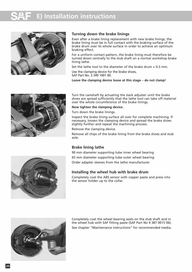
Turning down the brake liningsEven after a brake lining replacement with new brake linings, thebrake lining must be in full contact with the braking surface of thebrake drum over its whole surface in order to achieve an optimumbraking effect.
For a uniform contact pattern, the brake lining must therefore beturned down centrally to the stub shaft on a normal workshop brakelining lathe.
Set the lathe tool to the diameter of the brake drum + 0.3 mm.
Use the clamping device for the brake shoes, SAF Part No. 3 349 1001 00.
Leave the clamping device loose at this stage – do not clamp!
Turn the camshaft by actuating the slack adjuster until the brakeshoes are spread sufficiently that the lathe tool can take off materialover the whole circumference of the brake linings.
Now tighten the clamping device.
Turn down the brake linings.
Inspect the brake lining surface all over for complete machining. Ifnecessary, loosen the clamping device and spread the brake shoesslightly further and repeat the machining process.
Remove the clamping device.
Remove all chips of the brake lining from the brake shoes and stubaxle.
Brake lining lathe90 mm diameter supporting tube inner wheel bearing
65 mm diameter supporting tube outer wheel bearing
Order adapter sleeves from the lathe manufacturer.
Installing the wheel hub with brake drumCompletely coat the ABS sensor with copper paste and press into the sensor holder up to the collar.
Completely coat the wheel bearing seats on the stub shaft and in the wheel hub with SAF fitting paste (SAF Part No 4 387 0015 06).
See chapter “Maintenance instructions” for recommended media.
21
E) Installation instructions
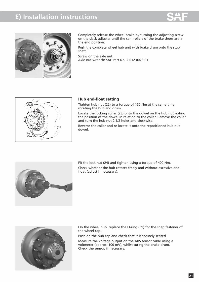
Completely release the wheel brake by turning the adjusting screwon the slack adjuster until the cam rollers of the brake shoes are inthe end position.
Push the complete wheel hub unit with brake drum onto the stubshaft.
Screw on the axle nut.Axle nut wrench: SAF Part No. 2 012 0023 01
Hub end-float settingTighten hub nut (22) to a torque of 150 Nm at the same time rotating the hub and drum.
Locate the locking collar (23) onto the dowel on the hub nut notingthe position of the dowel in relation to the collar. Remove the collarand turn the hub nut 2 1/2 holes anti-clockwise.
Reverse the collar and re-locate it onto the repositioned hub nutdowel.
Fit the lock nut (24) and tighten using a torque of 400 Nm.
Check whether the hub rotates freely and without excessive end-float (adjust if necessary).
On the wheel hub, replace the O-ring (39) for the snap fastener ofthe wheel cap.
Push on the hub cap and check that it is securely seated.
Measure the voltage output on the ABS sensor cable using a voltmeter (approx. 100 mV), whilst turing the brake drum. Check the sensor, if necessary.
22
E) Installation instructions
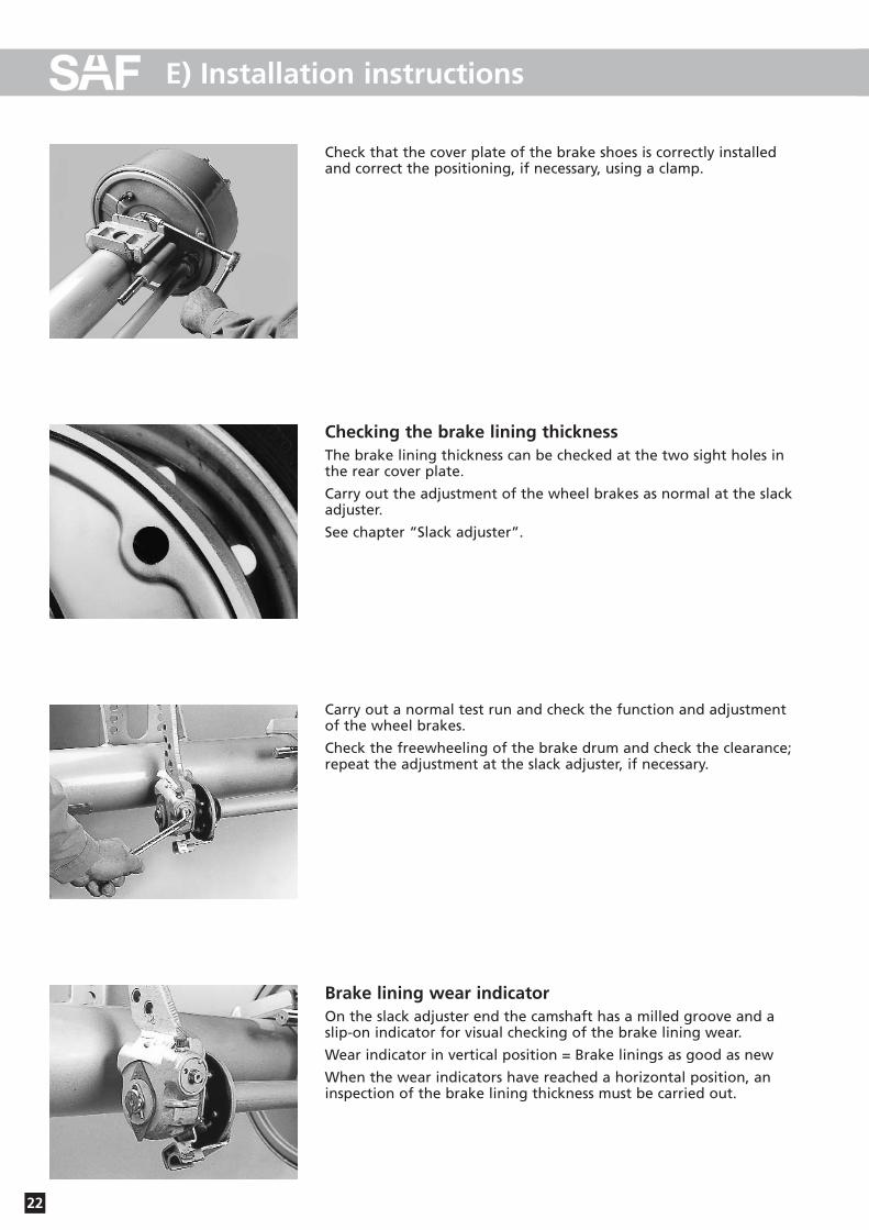
Check that the cover plate of the brake shoes is correctly installedand correct the positioning, if necessary, using a clamp.
Checking the brake lining thicknessThe brake lining thickness can be checked at the two sight holes inthe rear cover plate.
Carry out the adjustment of the wheel brakes as normal at the slackadjuster.
See chapter “Slack adjuster”.
Carry out a normal test run and check the function and adjustmentof the wheel brakes.
Check the freewheeling of the brake drum and check the clearance;repeat the adjustment at the slack adjuster, if necessary.
Brake lining wear indicatorOn the slack adjuster end the camshaft has a milled groove and a slip-on indicator for visual checking of the brake lining wear.
Wear indicator in vertical position = Brake linings as good as new
When the wear indicators have reached a horizontal position, aninspection of the brake lining thickness must be carried out.
23
E) Installation instructions
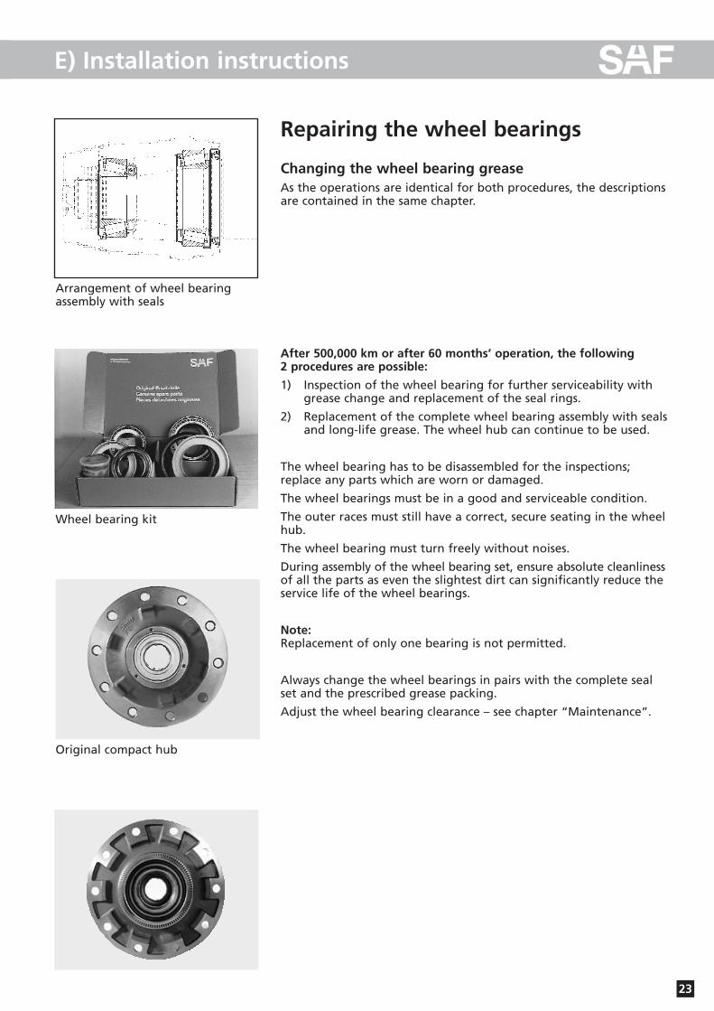
Repairing the wheel bearings
Changing the wheel bearing greaseAs the operations are identical for both procedures, the descriptionsare contained in the same chapter.
After 500,000 km or after 60 months’ operation, the following 2 procedures are possible:
1) Inspection of the wheel bearing for further serviceability with grease change and replacement of the seal rings.
2) Replacement of the complete wheel bearing assembly with sealsand long-life grease. The wheel hub can continue to be used.
The wheel bearing has to be disassembled for the inspections; replace any parts which are worn or damaged.
The wheel bearings must be in a good and serviceable condition.
The outer races must still have a correct, secure seating in the wheelhub.
The wheel bearing must turn freely without noises.
During assembly of the wheel bearing set, ensure absolute cleanlinessof all the parts as even the slightest dirt can significantly reduce theservice life of the wheel bearings.
Note:Replacement of only one bearing is not permitted.
Always change the wheel bearings in pairs with the complete sealset and the prescribed grease packing.
Adjust the wheel bearing clearance – see chapter “Maintenance”.
Wheel bearing kit
Original compact hub
Arrangement of wheel bearingassembly with seals
24
E) Installation instructions
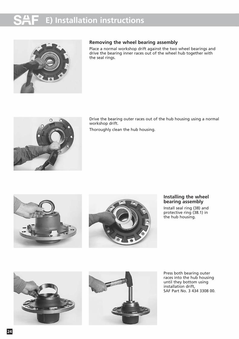
Removing the wheel bearing assemblyPlace a normal workshop drift against the two wheel bearings anddrive the bearing inner races out of the wheel hub together withthe seal rings.
Drive the bearing outer races out of the hub housing using a normalworkshop drift.
Thoroughly clean the hub housing.
Installing the wheelbearing assemblyInstall seal ring (38) and protective ring (38.1) in the hub housing.
Press both bearing outerraces into the hub housinguntil they bottom usinginstallation drift, SAF Part No. 3 434 3308 00.

25
E) Installation instructions
Pack both taper roller bearings with long-life grease.
Grease packing volume: Inner bearing 150 gOuter bearing 90 g
Pack the ring gap on the faceside of the bearing withlong-life grease.
Press in unitised seal (37) andouter sealing washer (38.2) using installation drift, SAF Part No. 3 434 1036 00.
Install the exciter ring.
Installation drift, SAF Part No. 3 434 3308 00
If the hubs are subsequently painted, ensure that the contact surfacefor the wheel and brake drum are not painted.
26
F) Slack adjuster
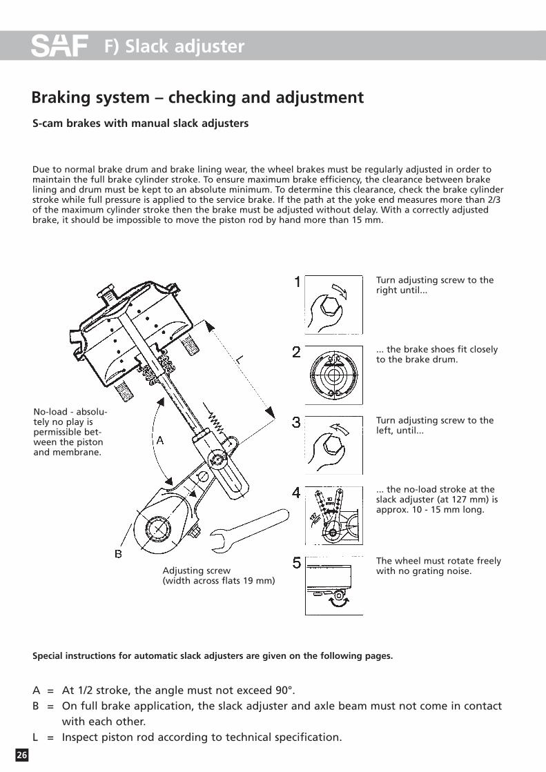
Braking system – checking and adjustmentS-cam brakes with manual slack adjusters
Due to normal brake drum and brake lining wear, the wheel brakes must be regularly adjusted in order tomaintain the full brake cylinder stroke. To ensure maximum brake efficiency, the clearance between brakelining and drum must be kept to an absolute minimum. To determine this clearance, check the brake cylinderstroke while full pressure is applied to the service brake. If the path at the yoke end measures more than 2/3of the maximum cylinder stroke then the brake must be adjusted without delay. With a correctly adjustedbrake, it should be impossible to move the piston rod by hand more than 15 mm.
Turn adjusting screw to theright until...
... the brake shoes fit closelyto the brake drum.
Turn adjusting screw to theleft, until...
... the no-load stroke at theslack adjuster (at 127 mm) isapprox. 10 - 15 mm long.
The wheel must rotate freelywith no grating noise.
No-load - absolu-tely no play ispermissible bet-ween the pistonand membrane.
Adjusting screw (width across flats 19 mm)
Special instructions for automatic slack adjusters are given on the following pages.
A = At 1/2 stroke, the angle must not exceed 90°.B = On full brake application, the slack adjuster and axle beam must not come in contact
with each other.L = Inspect piston rod according to technical specification.
27
F) Slack adjuster
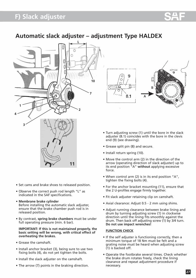
Automatic slack adjuster – adjustment Type HALDEX
• Set cams and brake shoes to released position.
• Observe the correct push rod length “L” as indicated in the SAF specifications.
• Membrane brake cylinderBefore installing the automatic slack adjuster, ensure that the brake chamber push rod is in released position.
• By contrast, spring brake chambers must be underfull operating pressure (min. 6 bar).
IMPORTANT: If this is not maintained properly, thebasic setting will be wrong, with critical effect ofoverheating the brakes.
• Grease the camshaft.
• Install anchor bracket (3), being sure to use twofixing bolts (4), do not yet tighten the bolts.
• Install the slack adjuster on the camshaft.
• The arrow (7) points in the braking direction.
• Turn adjusting screw (1) until the bore in the slackadjuster (8.1) coincides with the bore in the clevisend (9) (see drawing).
• Grease split pin (8) and secure.
• Install return spring (10).
• Move the control arm (2) in the direction of thearrow (operating direction of slack adjuster) up toits end position “A” without applying excessiveforce.
• When control arm (2) is in its end position “A”, tighten the fixing bolts (4).
• For the anchor bracket mounting (11), ensure thatthe 2 U-profiles engage firmly together.
• Fit slack adjuster retaining clip on camshaft.
• Axial clearance: Adjust 0.5 - 2 mm using shims.
• Adjust running clearance between brake lining anddrum by turning adjusting screw (1) in clockwisedirection until the lining fits smoothly against thedrum. Then back off adjusting screw (1) by 3/4 turn. Do not use impact wrenches!
FUNCTION CHECK
• If the self adjuster is functioning correctly, then aminimum torque of 18 Nm must be felt and a grating noise must be heard when adjusting screw(1) is backed off.
• Operate the footbrake several times. Check whetherthe brake drum rotates freely, check the lining clearance and repeat adjustment procedure ifnecessary.
11
2
1
4
3
7
2
10
L

F) Slack adjuster
28
Automatic slack adjuster - adjustment Type S-ABA
• Set cams and brake shoes to released position.
• Observe the correct push rod length “L” as indicated in the SAF specifications.
• Membrane brake cylinderBefore installing the automatic slack adjuster, ensure that the brake chamber push rod is in released position.
• By contrast, spring brake chambers must be underfull operating pressure (min. 6 bar).
IMPORTANT: If this is not maintained properly, thebasic setting will be wrong, with critical effect ofoverheating the brakes.
• Grease the camshaft.
• Install anchor bracket (3), being sure to use twofixing bolts (4), do not yet tighten the bolts.
• Install the slack adjuster on the camshaft.
• The arrow (7) points in the braking direction.
• Turn adjusting screw (1) until the bore in the slackadjuster (8.1) coincides with the bore in the clevisend (9) (see drawing).
• For the fixed point mounting, ensure that the 2 U-profiles engage firmly inside one another.
• Grease split pin (8) and secure.
• Install return spring (10).
• Mount slack adjuster on camshaft.
• Axial clearance: Adjust 0.5 - 2 mm using shims.
• Adjust control arm.
• Possible adjustment range for control lever position (slack adjuster) up to its end position without applying excessive force.
• Adjust running clearance between brake lining anddrum by turning adjusting screw (1) in clockwisedirection until the lining fits smoothly against thedrum. Then back off adjusting screw (1) by 3/4 turn. Do not use impact wrenches!
FUNCTION CHECK
• If the self adjuster is functioning correctly, then aminimum torque of 18 Nm must be felt and a grating noise must be heard when adjusting screw(1) is backed off.
• Operate the footbrake several times. Check whetherthe brake drum rotates freely, check the lining clearance and repeat adjustment procedure ifnecessary.
2
L
2
7
10
3
4
1
G) Track control
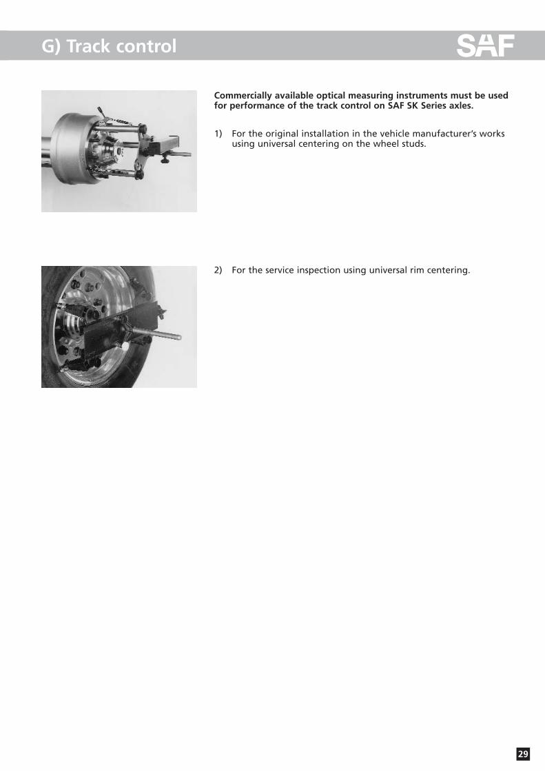
Commercially available optical measuring instruments must be usedfor performance of the track control on SAF SK Series axles.
1) For the original installation in the vehicle manufacturer’s works using universal centering on the wheel studs.
2) For the service inspection using universal rim centering.
29
G) Track control
30
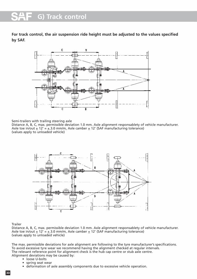
TrailerDistance A, B, C, max. permissible deviation 1.0 mm. Axle alignment responsablety of vehicle manufacturer.Axle toe in/out + 12’ = + 3.0 mm/m, Axle camber + 12’ (SAF manufacturing tolerance)(values apply to unloaded vehicle)
The max. permissible deviations for axle alignment are following to the tyre manufacturer’s specifications. To avoid excessive tyre wear we recommend having the alignment checked at regular intervals.The relevant reference point for alignment check is the hub cap centre or stub axle centre.Alignment deviations may be caused by:
• loose U-bolts• spring seat wear• deformation of axle assembly components due to excessive vehicle operation.
For track control, the air suspension ride height must be adjusted to the values specified by SAF.
Semi-trailers with trailing steering axleDistance A, B, C, max. permissible deviation 1.0 mm. Axle alignment responsablety of vehicle manufacturer.Axle toe in/out + 12’ = + 3.0 mm/m, Axle camber + 12’ (SAF manufacturing tolerance)(values apply to unloaded vehicle)

1. Lever for hub capSAF Part No. 1 434 1041 00
2. Axle nut wrench W.A.F. 85SAF Part No. 2 012 0023 01
3. Wheel hub pullerSAF Part No. 4 434 3822 00
4. Installation drift for unitised sealSAF Part No. 3 434 1036 00
H) Service tools
31

5. Wheel bearing installation drift SAF Part No. 3 434 3308 00
6. Brake shoe clamping deviceSAF Part No. 3 349 1001 00
7. Clamping rings for brake drum latheSAF Part No. 3 434 1060 00
H) Service tools
32
33
I) Tightening torque in Nm
M 8 W.A.F. 13 25 35 41
M 8 x 1 27 38 45
M 10 W.A.F. 17 / 16 49 69 83
M 10 x 1 52 73 88
M 12 W.A.F. 19 / 18 86 120 145
M 12 x 15 90 125 150
M 14 W.A.F. 22 / 21 135 190 230
M 14 x 1.5 150 210 250
M 16 W.A.F. 24 210 300 355
M 16 x 1.5 225 315 380
M 18 W.A.F. 27 300 405 485
M 18 x 1.5 325 460 550
M 20 W.A.F. 30 410 580 690
M 20 x 1.5 460 640 770
M 22 W.A.F. 32 550 780 930
M 22 x 1.5 610 860 1050
M 24 W.A.F. 36 710 1000 1200
M 24 x 2 780 1100 1300
M 27 W.A.F. 41 1050 1500 1800
M 27 x 2 1150 1600 1950
M 30 W.A.F. 46 1450 2000 2400
M 30 x 2 1600 2250 2700
M 36 x 2 W.A.F. 55 2450 3450 4150
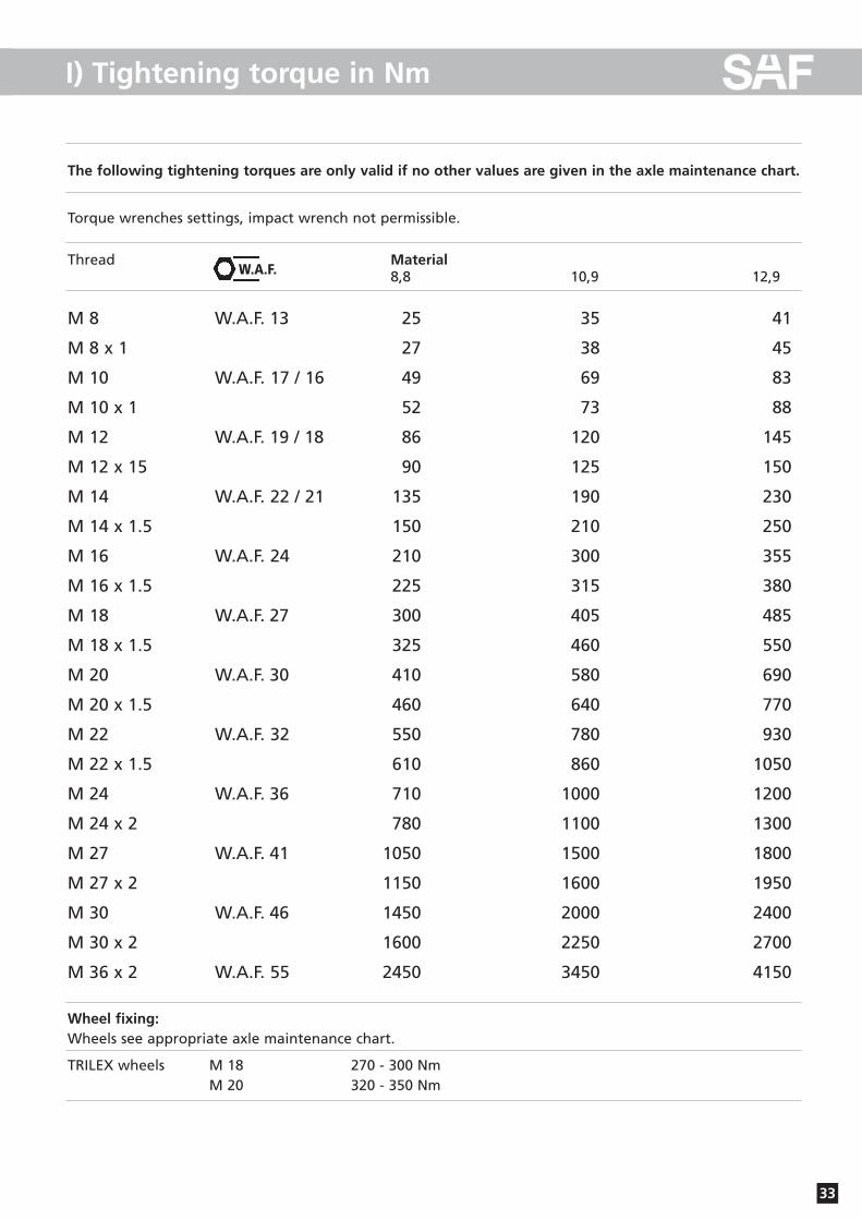
Wheel fixing:Wheels see appropriate axle maintenance chart.
TRILEX wheels M 18 270 - 300 NmM 20 320 - 350 Nm
The following tightening torques are only valid if no other values are given in the axle maintenance chart.
Torque wrenches settings, impact wrench not permissible.
Thread Material8,8 10,9 12,9W.A.F.

NonStopService 24Soforthilfe im Pannenfall
Support in the case of service
Otto Sauer Achsenfabrik GmbH · Hauptstraße 26 · D-63856 Bessenbach Tel +49 (0) 60 95 / 301-0 · Fax +49 (0) 60 95 / 301-259 · www.saf-axles.com
· Im Servicefall wählen Sie bitte immer die Rufnummer Ihres Heimatlandes.
· In the case of service please always dial the number of your own country.
+43 3 62 27 23 21+32 59 33 07 07
+30 21 09 40 19 80+386 26 16 58 35+41 19 08 64 90
+42 02 61 10 45 0600800 72 37 37 84 / +49 73 33 80 81 58
+45 75 72 74 74+34 9 13 82 68 41
+372 697 91 96+3 33 88 72 06 43+35 8 93 51 31 33
+41 19 08 64 90+44 87 02 42 02 37+30 21 09 40 19 80
+36 13 45 17 27+386 26 16 58 35
+39 02 66 16 55 74+44 87 02 42 02 37
+32 59 33 07 07+372 697 91 96+372 697 91 96
+33 3 88 72 06 43+386 26 16 58 35+45 75 72 74 74+32 59 33 07 07
+34 9 13 82 68 41+48 6 18 31 98 70+40 2 12 50 02 60
+39 02 66 16 55 74+45 75 72 74 74
+42 02 61 10 45 06+386 26 16 58 35
+90 21 22 75 13 21+386 26 16 58 35
Inlandhome country
03 62 27 23 210 59 33 07 07+30 21 09 40 19 80+386 26 16 58 350 19 08 64 902 61 10 45 060800 72 37 37 84 / 0 73 33 80 81 5875 72 74 749 02 18 19 92697 91 9603 88 72 06 430 93 51 31 33+41 19 08 64 900 87 02 42 02 3721 09 40 19 8006 13 45 17 27+386 26 16 58 3502 66 16 55 74+44 87 02 42 02 37+32 59 33 07 07+372 697 91 96+372 697 91 96+33 3 88 72 06 43+386 26 16 58 35+45 75 72 74 74+32 59 33 07 07+34 9 13 82 68 4106 18 31 98 7002 12 50 02 60+39 02 66 16 55 74+45 75 72 74 74+42 02 61 10 45 060 26 16 58 350 21 22 75 13 21+386 26 16 58 35
Vom Auslandfrom abroad
�A
B
BG
BIH
CH
CZ
D
DK
E
EST
F
FIN
FL
GB
GR
H
HR
I
IRL
L
LT
LV
MC
MK
N
NL
P
PL
RO
RSM
S
SK
SLO
TR
YU
www.saf-axles.com
SV10
903G
B E
ditio
n 01
/200
6 ·L
ast u
pdat
ed 2
006-
01-3
1 · A
men
dmen
ts a
nd e
rrors
rese
rved
© S
AF