maintenance of surface water level sensors
TRANSCRIPT

Site Selection and Installation of
Surface Water Level Instruments
Smt. Lata Gupta
Scientist ‘C’
CWPRS

When selecting sites for water level monitoring stations, existing
infrastructure, access, and security are the most important parameters to
be considered. Make proper arrangement for fencing and lock system to
protect instrument and civil structure from theft.
Human interference with hydrometric installations is a problem in our
country. This issue has to be given serious consideration during the site
selection process. The sensor, solar panel, battery, antenna, cables and
connectors should be protected from theft. From the security point of view,
choose a site where a permanent caretaker can be provided.
If a choice has to be made between two hydraulically similar sites, the final
selection should be made in favour of the site which has fewer problems
due to human interference and law and order.

There should be enough land near the site to install various
instruments. In some cases land availability is a challenge along the
river bank.
For successful operation and maintenance of the surface water level
monitoring station, local manpower, financial and logistic support
resources have to be available.

• The site should be away from
the back water zone caused by
any structure on the river.
• The site should be far away
from HT lines, frequency
converter, variable frequency
motor and high power electric
equipment.
• Sites with a tendency for
formation of vortices, reverse
flow or dead water shall be
avoided.
• Avoid submerged obstructions
such as rocks or bridge piers
that disturb the water level.

• Select the site where an
instrument shelter can be
easily installed. The
instrument shelter should
be high enough to be
above the flood level.
• The electrical grounding for
all electronic and electrical
equipment should be done
by following standard
CPWD procedure.
• The gauge site should be
far enough upstream from
the confluence with another
stream and from tidal
effect.

• The station should be installed
so that sensitive equipment
such as the data logger,
batteries, and telemetry radios
and antennas are located well
above expected high water.
• Zones of high turbulence,
eddies, and super elevation
should be avoided.
• The site should be accessible
by motor vehicle during all
weather and streamflow
conditions.
• Sites where foam is present,
should be avoided.
• Avoid sites where there is a
heavy traffic on bridge.
• There should be a good GSM
signal or a clear line-of-site to
the INSAT or VSAT satellite
system.

• The water surface must be
as smooth as possible in the
area of the sensor beam.
• The site should be cleared of
bushes, trees and other
obstructions that would
make access hazardous.
• Sites where high sediment
deposition or scouring
occurs should be avoided.
• Site should be easily
accessible for maintenance /
repairing of the instruments.
• The entire unit has to be
adequately protected against
lightning and build of staticcharges.
• Sites which are subject to
weed growth, should be
avoided.

• A reference gauge such as a staff gauge, wire weight gauge, or
reference mark should be established at each gauging station.
• Solar panels should be oriented to maximize daily sunlight
absorption.
• Locations which are subject to high turbulence or wind effects
should be avoided.
• Data logger and transmitter should be secured in a NEMA type 4
enclosures or equivalent to prevent access by water, dust, or
insects.

Installation requirements for Radar and Ultrasonic Sensor Sites

• Installation of radar sensor requires some sort of bridge or platform to
mount the sensor.
• Radar or ultrasonic sensors should have a direct vertical shot to the
water surface with no obstruction of their beams within the cone. Sensor
must not have any object within the area of signal projection.
• Many dams, bridges and stilling wells have pillars, pipes, ladders, or
other equipment attached to the walls. If a sensor beam hits the
obstacle, it will return a false reading.

The radar sensor should be mounted directly above the water surface, suchthat the radar beam is perpendicular to the water.
There should be a clear path between the sensor and the water to avoid falsereflections.

The radar sensor’s beam path should be free of excessive turbulence,splashing, waves, pipes, wires, and other obstructions that coulddisturb the measurement.
Avoid turbulent areas and areas where obstructions in the waterway
or bridge piers cause changes in the water level. Zones of high
turbulence, eddies should be avoided.

The picture shows a site where there is a bend after bridge; hence it is
not a good site for water level monitoring.
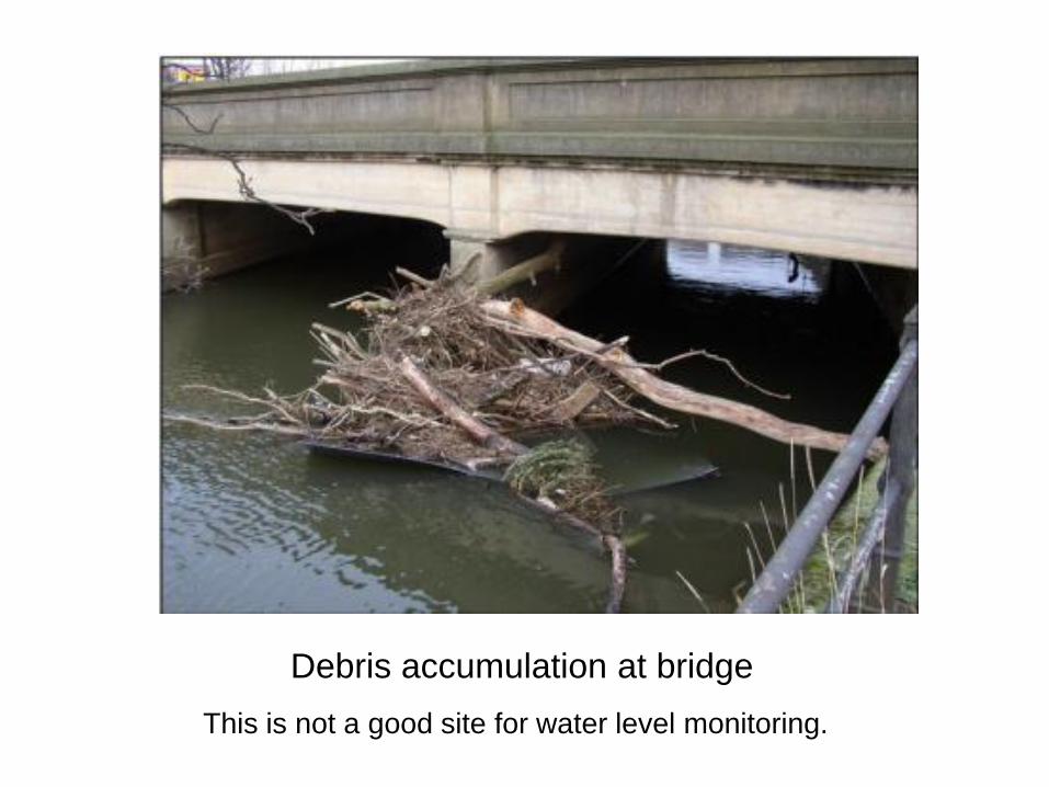
Debris accumulation at bridge
This is not a good site for water level monitoring.
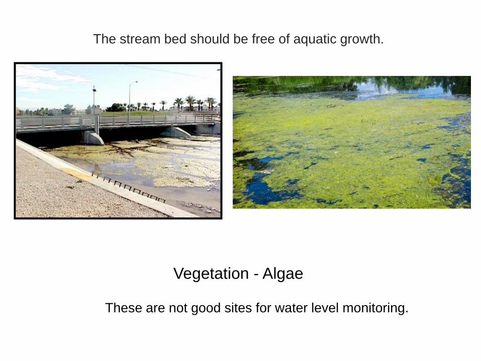
Vegetation - Algae
The stream bed should be free of aquatic growth.
These are not good sites for water level monitoring.

Floating debris accumulation at the front of the bridge pier.
Avoid such site locations for Radar and Ultrasonic sensor.

The picture below shows a section of breading river, where a water level station should not be installed.

Make certain the radar sensor is mounted high enough to avoidbeing submerged during high water or flood conditions. Theheight of the sensor installation should be carefully chosen.
Radar Installed at Khadakwasla Dam

The water surface must be as smooth as possible in the area of the
radar sensor beam.
Waves and ripples on water surface may cause problems for radar
water level measurement.
Instead of reflecting back upwards towards the antenna, radar signals
hitting a turbulent surface may scatter and disperse.
Thus a lot of signal energy strength can be lost (almost 90%).
This gives radar problems with obtaining an accurate and reliable
measurement.

Installation requirements for Shaft Encoder sites

• Shaft encoder cannot be
installed directly in the river in
turbulent flowing water. It has to
be installed in a stilling well.
• Ideal site for shaft encoder type
water level sensor is the stable
river bed where the channel
does not change or migrate
away from intakes.
• Site with minimal sedimentation
are preferred.
• The horizontal pipes connecting
to the river get choked with
sediment and sometimes it is
difficult to keep them clear.

At some places, a steel
pipe of diameter about
200mm is attached to the
bridge pier, to act as a
stilling well. This pipe is
open at the bottom end.
Since it is installed in the
river directly, there are no
horizontal pipes to get
chocked. This drastically
reduces the overall cost
and also gets rid of the
problem of chocked
connecting pipes.
Shaft encoder installation at ISP dam, M.P.

Installation of a shaft encoder from the side of a bridge. A steel structure is
erected on the side of the bridge, with a 6-inch diameter pipe hanging from
the bridge deck, extending till the river bed.
The shaft encoder with a pulley is installed at the top of the pipe. The float
and counterweight are hanging from the pulley.
A shaft encoder installed on the side of a bridge in Gujarat

Shaft Encoder Type Water Level Sensor at Bhakhra Nangal Dam
Graduated Tape should be of high quality to withstand harsh and
humid environment, it should not get twisted or wrinkled while
operation.

Installation requirements for Bubbler Sites

• Bubbler systems work well in
open channels as well as in
reservoirs.
• It is installed directly in the river
bed. Electronics part is installed
away from the water, only bubbler
tubing contacts the water.
Therefore main part i.e. sensor is
not affected by any sediment
deposited on it.
• A large Nitrogen tank is used
which must be periodically
refilled.

Installation requirements for Pressure Transducer Sites

• Pressure sensor is installed directly in the river, therefore it has the risk of
being damaged in a high flood or by rolling boulders.
• The reading of pressure sensor is also affected by the weight of any sediment
deposited over it.
• Always install transducer in cool and deep pool to reduce turbulence and noisy
data.
• Once the costly sensor is damaged, it is difficult to replace it till the high-flow
season is over. Till then all the data is lost.
• More susceptible to unintentional damage by animals or people.

Summary
• Select site with stable river bed where the channel does not
change or migrate away from intakes.
• There should be a clear path between the sensor and the
water to avoid false reflections.
• Site with minimal sedimentation is preferred.
• The water surface must be as smooth as possible in the area
of the radar sensor beam.

Thank you