major project pawan
DESCRIPTION
PROJECTTRANSCRIPT

Shock absorbers at the face of automobile vehicle for
the safety during sudden collision

ABSTRACT
An automobile vehicle safety may have become an issue almost from the beginning of
mechanized road vehicle development. Automobile safety and the avoidance of
automobile accidents or the minimization of harmful effects of accidents, in particular as
pertaining to human life and health, this project has been carried out. Numerous safety
features have been built into cars for years, some for the safety of car's occupants only,
and some for the safety of others.
Two hydraulic springs (shock absorbers) are attached to the front face of automobile
vehicle to absorb the impact load during accidents. This type of system can be easily
attached to all currently manufacture automobiles.
This project will also help to save the life of driver during accidents and collisions, since
suggestion for modifying the design of an automobile vehicle are presented. The design
of driver’s seat is also modified to save his/her life during accident.
The Major Project entitled “Shock absorbers at the face of automobile vehicle for the
safety during sudden collision” Worked on the principal of shock absorbing during
impact loading and operated by two compression springs.
This work, if implemented, would definitely help to saving the life of drivers during car
accident.
CHAPTER 1
INTRODUCTION

1.1 What is an automobile?
An automobile or motor car is a wheeled motor vehicle for transporting passengers,
which also carries its own engine or motor. Most definitions of the term specify that
automobiles are designed to run primarily on roads, to have seating for one to eight
people, to typically have four wheels, and to be constructed principally for the transport
of people rather than goods. However, the term is far from precise because there are
many types of vehicles that do similar tasks.
Automobile comes via the French language, from the Greek language by combining auto
[self] with mobiles [moving]; meaning a vehicle that moves itself, rather than being
pulled or pushed by a separate animal or another vehicle.
Most automobiles in use today are propelled by gasoline (also known as petrol) or diesel
internal combustion engines, which are known to cause air pollution and are also blamed
for contributing to climate change and global warming. Increasing costs of oil-based
fuels, tightening environmental laws and restrictions on greenhouse gas emissions are
propelling work on alternative power systems for automobiles. Efforts to improve or
replace existing technologies include the development of hybrid vehicles, and electric and
hydrogen vehicles which do not release pollution into the air.
1.2 Fuel and propulsion technologies
1.2.1 Diesel
Diesel-engine cars have long been popular in Europe with the first models being
introduced in the 1930s by Mercedes Benz and Citroen. The main benefit of diesel
engines is a 50% fuel burn efficiency compared with 27% in the best gasoline engines. A
down-side of the diesel is the presence in the exhaust gases of fine soot particulates and
manufacturers are now starting to fit filters to remove these. Many diesel-powered cars
can also run with little or no modifications on 100% bio-diesel.
1.2.2 Gasoline
Gasoline engines have the advantage over diesel in being lighter and able to work at
higher rotational speeds and they are the usual choice for fitting in high-performance

sports cars. Continuous development of gasoline engines for over a hundred years has
produced improvements in efficiency and reduced pollution. The carburetor was used on
nearly all road car engines until the 1980s but it was long realised better control of the
fuel/air mixture could be achieved with fuel injection. Indirect fuel injection was first
used in aircraft engines from 1909, in racing car engines from the 1930s, and road cars
from the late 1950s.[14] Gasoline Direct Injection (GDI) is now starting to appear in
production vehicles such as the 2007 (Mark II) BMW Mini. Exhaust gases are also
cleaned up by fitting a catalytic converter into the exhaust system. Clean air legislation in
many of the car industries most important markets have made both catalysts and fuel
injection virtually universal fittings. Most modern gasoline engines also are capable of
running with up to 15% ethanol mixed into the gasoline - older vehicles may have seals
and hoses that can be harmed by ethanol. With a small amount of redesign, gasoline-
powered vehicles can run on ethanol concentrations as high as 85%. 100% ethanol is
used in some parts of the world (such as Brazil), but vehicles must be started on pure
gasoline and switched over to ethanol once the engine is running. Most gasoline engine
cars can also run on LPG with the addition of an LPG tank for fuel storage and
carburetion modifications to add an LPG mixer. LPG produces fewer toxic emissions and
is a popular fuel for fork lift trucks that have to operate inside buildings.
1.2.3 Bio-Fuels
Ethanol, other alcohol fuels (bio-butane) and bio-gasoline have widespread use an
automotive fuel. Most alcohols have less energy per liter than gasoline and are usually
blended with gasoline. Alcohols are used for a variety of reasons - to increase octane, to
improve emissions, and as an alternative to petroleum based fuel, since they can be made
from agricultural crops. Brazil's ethanol program provides about 20% of the nation's
automotive fuel needs, as a result of the mandatory use of E25 blend of gasoline
throughout the country, 3 million cars that operate on pure ethanol, and 6 million dual or
flexible-fuel vehicles sold since 2003 that run on any mix of ethanol and gasoline. The
commercial success of "flex" vehicles, as they are popularly known, have allowed
sugarcane based ethanol fuel to achieve a 50% market share of the gasoline market by
April 2008.

1.2.4 Electric
The first electric cars were built around 1832, well before internal combustion powered
cars appeared. For a period of time electrics were considered superior due to the silent
nature of electric motors compared to the very loud noise of the gasoline engine. This
advantage was removed with Hiram Percy Maxim's invention of the muffler in 1897.
Thereafter internal combustion powered cars had two critical advantages: 1) long range
and 2) high specific energy (far lower weight of petrol fuel versus weight of batteries).
The building of battery electric vehicles that could rival internal combustion models had
to wait for the introduction of modern semiconductor controls and improved batteries.
Because they can deliver a high torque at low revolutions electric cars do not require such
a complex drive train and transmission as internal combustion powered cars. Some post-
2000 electric car designs such as the Venturi Fétish are able to accelerate from 0-60 mph
(96 km/h) in 4.0 seconds with a top speed around 130 mph (210 km/h). Others have a
range of 250 miles (400 km) on the EPA highway cycle requiring 3-1/2 hours to
completely charge. Equivalent fuel efficiency to internal combustion is not well defined
but some press reports give it at around 135 mpg–U.S. (1.74 L/100 km / 162.1 mpg–imp).
1.2.5 Steam
Steam power, usually using an oil- or gas-heated boiler, was also in use until the 1930s
but had the major disadvantage of being unable to power the car until boiler pressure was
available (although the newer models could achieve this in well under a minute). It has
the advantage of being able to produce very low emissions as the combustion process can
be carefully controlled. Its disadvantages include poor heat efficiency and extensive
requirements for electric auxiliaries.
1.2.6 Air

A compressed air car is an alternative fuel car that uses a motor powered by compressed
air. The car can be powered solely by air, or by air combined (as in a hybrid electric
vehicle) with gasoline/diesel/ethanol or electric plant and regenerative braking. Instead of
mixing fuel with air and burning it to drive pistons with hot expanding gases; compressed
air cars use the expansion of compressed air to drive their pistons. Several prototypes are
available already and scheduled for worldwide sale by the end of 2008. Companies
releasing this type of car include Tata Motors and Motor Development International
(MDI).
1.2.7 Gas turbine
In the 1950s there was a brief interest in using gas turbine engines and several makers
including Rover and Chrysler produced prototypes. In spite of the power units being very
compact, high fuel consumption, severe delay in throttle response, and lack of engine
braking meant no cars reached production.
1.3 Automobiles Type
1.3.1 Car
A car is generally four wheeled motor vehicle for transporting passengers. Most
definitions of the term specify that cars are designed to run primarily on roads, to have
seating for one to eight people, to typically have four wheels, and to be constructed
principally for the transport of people rather than goods.
1.3.2 Truck
A truck is a vehicle for carrying goods and materials. The word "truck" possibly derives
from the Greek "trochos", meaning "wheel." In North America, the big wheels of wagons
were called trucks. When the gasoline-engine driven trucks came into fashion, these were
called "motor trucks." Lorry is a term from the United Kingdom and the Republic of
Ireland, but is only used for the medium and heavy types, i.e. a van, a pickup or a Jeep

would never be regarded as a lorry. Other languages have loanwords based on these
terms, such as the Malay language and the Spanish language in northern Mexico.
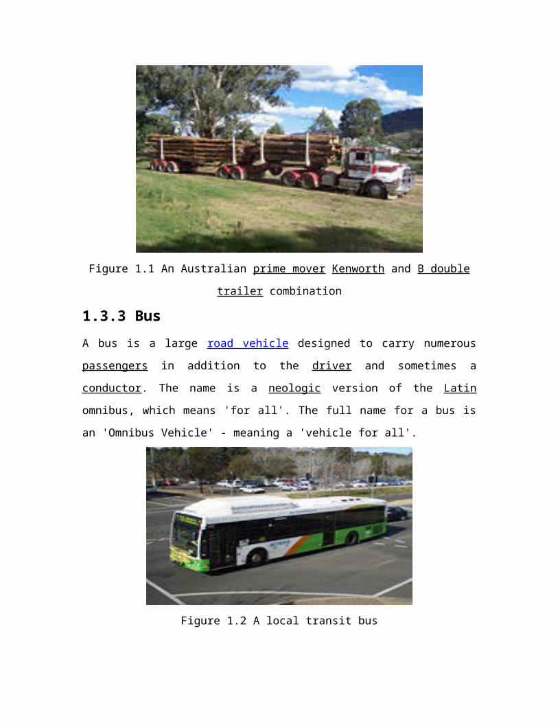
Figure 1.1 An Australian prime mover Kenworth and B double trailer combination
1.3.3 Bus
A bus is a large road vehicle designed to carry numerous passengers in addition to the
driver and sometimes a conductor. The name is a neologic version of the Latin omnibus,
which means 'for all'. The full name for a bus is an 'Omnibus Vehicle' - meaning a
'vehicle for all'.
Figure 1.2 A local transit bus
Early bus manufacturing grew out of carriage coachwork builders, and later out of
automobile or truck manufacturing enterprises. Early buses were merely a bus body fitted

to a truck chassis. This body plus chassis approach has continued into modern specialist
manufacturers, although there also exists integral manufacturers of complete bus or coach
products. Specialist builders also build buses for special uses, or modify standard
products. Modern day bus manufacturing combines a number of advanced technologies,
including GPS location, passenger information systems and electronic control, and
increasingly features technology to aid accessibility. Manufacturers are also investigating
alternatives to the traditional combustion engine powered approach, with electric, fuel
cell and hybrid bus technologies. As with the auto-industry, bus manufacturing is
developing from a localized enterprise to increasingly becoming a globalize industry,
with groups of manufacturers forming consortia. As with the car industry, new models
are often exhibited at industry motor shows.

CHAPTER 2
Automobile Engine

2.1 Introduction
All the automobile engines work on the principal of internal combustion engine i.e. an
automobile engine is an internal combustion engine.
2.2 Internal combustion engine
The internal combustion engine is an engine in which the combustion of fuel and an
oxidizer (typically air) occurs in a confined space called a combustion chamber. This
exothermic reaction creates gases at high temperature and pressure, which are permitted
to expand. Internal combustion engines are defined by the useful work that is performed
by the expanding hot gases acting directly to cause the movement of solid parts of the
engine.
Figure 2.1 A colored automobile engine
The term Internal Combustion Engine (ICE) is often used to refer to an engine in which
combustion is intermittent, such as a Wankel engine or a reciprocating piston engine in
which there is controlled movement of pistons, cranks, cams, or rods. However,
continuous combustion engines such as jet engines, most rockets, and many gas turbines
are also classified as types of internal combustion engines. This contrasts with external
combustion engines such as steam engines and Stirling engines that use a separate
combustion chamber to heat a separate working fluid—which then in turn does work, for
example, by moving a piston or a turbine.
2.2.1 Applications
The motion of internal combustion engines is usually performed by the controlled
movement of pistons, cranks, rods, rotors, or even the entire engine itself.
Internal combustion engines are most commonly used for mobile propulsion in vehicles
and portable machinery. In mobile equipment, internal combustion is advantageous since
it can provide high power-to-weight ratios together with excellent fuel energy-density.
Generally using a petroleum called All-Petroleum Internal Combustion Engine Vehicles
or APICEVs, these engines have appeared in transport in almost all automobiles, trucks,
motorcycles, boats, and in a wide variety of aircraft and locomotives.
Internal combustion engines appear in the form of gas turbines as well where a very high
power is required, such as in jet aircraft, helicopters, and large ships. They are also
frequently used for electric generators and by industry.

2.2.2 Operation
Internal combustion engines have 4 basic steps:
Intake :Combustible mixtures are emplaced in the combustion chamber
Compression :The mixtures are placed under pressure
Combustion/Expansion :The mixture is burnt, almost invariably a deflagration,
although a few systems involve detonation. The hot mixture is expanded, pressing
on and moving parts of the engine and performing useful work.
Exhaust :The cooled combustion products are exhausted
Many engines overlap these steps in time; jet engines do all steps simultaneously at
different parts of the engines. Some internal combustion engines have extra steps.
Figure 2.2 A four-stroke cycle (or Otto cycle)
2.2.3 Combustion

All internal combustion engines depend on the exothermic chemical process of
combustion: the reaction of a fuel, typically with oxygen from the air—although other
oxidizers such as nitrous oxide may be employed. The combustion process typically
results in the production of a great quantity of heat, as well as the production of steam
and carbon dioxide and other chemicals at very high temperature; the temperature
reached is determined by the chemical make up of the fuel and oxidizers.
The most common modern fuels are made up of hydrocarbons and are derived mostly
from petroleum. These include the fuels known as diesel fuel, gasoline and petroleum
gas, and the rarer use of propane. Except for the fuel delivery components, most internal
combustion engines that are designed for gasoline use can run on natural gas or liquefied
petroleum gases without major modifications. Liquid and gaseous biofuels, such as
ethanol and bio-diesel (a form of diesel fuel that is produced from crops that yield
triglycerides such as soybean oil), can also be used. Some engines with appropriate
modifications can also run on hydrogen gas.
All internal combustion engines must achieve ignition in their cylinders to create
combustion. Typically engines use either a spark ignition (SI) method or a compression
ignition (CI) system. In the past, other methods using hot tubes or flames have been used.
(a) Gasoline Ignition Process
Gasoline engine ignition systems generally rely on a combination of a lead-acid battery
and an induction coil to provide a high-voltage electrical spark to ignite the air-fuel mix
in the engine's cylinders. This battery is recharged during operation using an electricity-
generating device such as an alternator or generator driven by the engine. Gasoline
engines take in a mixture of air and gasoline and compress to less than 185 psi, then use a
spark plug to ignite the mixture when it is compressed by the piston head in each
cylinder.
(b) Diesel Ignition Process
Diesel engines and HCCI engines rely solely on heat and pressure created by the engine
in its compression process for ignition. The compression level that occurs is usually twice
or more than a gasoline engine. Diesel engines will take in air only, and shortly before
peak compression, a small quantity of diesel fuel is sprayed into the cylinder via a fuel
injector that allows the fuel to instantly ignite. HCCI type engines will take in both air
and fuel but continue to rely on an unaided auto-combustion process, due to higher
pressures and heat. This is also why diesel and HCCI engines are more susceptible to
cold-starting issues, although they will run just as well in cold weather once started. Light
duty diesel engines in automobiles and light trucks employ glow plugs that pre-heat the
combustion chamber just before starting to reduce no-start conditions in cold weather.
Most diesels also have a battery and charging system; nevertheless, this system is
secondary and is added by manufacturers as a luxury for the ease of starting, turning fuel
on and off (which can also be done via a switch or mechanical apparatus), and for
running auxiliary electrical components and accessories. Most new engines rely on
electrical and electronic control systems that also control the combustion process to
increase efficiency and reduce emissions.
2.2.4 Measures of engine performance
Engine types vary greatly in a number of different ways:
Energy efficiency
Fuel/propellant consumption (brake specific fuel consumption for shaft engines,
thrust specific fuel consumption for jet engines)

Power to weight ratio
Thrust to weight ratio
Torque curves (for shaft engines)
(a) Energy Efficiency
Once ignited and burnt, the combustion products—hot gases—have more available
thermal energy than the original compressed fuel-air mixture (which had higher chemical
energy). The available energy is manifested as high temperature and pressure that can be
translated into work by the engine. In a reciprocating engine, the high-pressure gases
inside the cylinders drive the engine's pistons.
Once the available energy has been removed, the remaining hot gases are vented (often
by opening a valve or exposing the exhaust outlet) and this allows the piston to return to
its previous position (top dead center, or TDC). The piston can then proceed to the next
phase of its cycle, which varies between engines. Any heat that isn't translated into work
is normally considered a waste product and is removed from the engine either by an air or
liquid cooling system.
Engine efficiency can be discussed in a number of ways but it usually involves a
comparison of the total chemical energy in the fuels, and the useful energy abstracted
from the fuels in the form of kinetic energy. The most fundamental and abstract
discussion of engine efficiency is the thermodynamic limit for abstracting energy from
the fuel defined by a thermodynamic cycle. The most comprehensive is the empirical fuel
economy of the total engine system for accomplishing a desired task; for example, the
miles per gallon accumulated.

Internal combustion engines are primarily heat engines and as such the phenomenon that
limits their efficiency is described by thermodynamic cycles. None of these cycles exceed
the limit defined by the Carnot cycle which states that the overall efficiency is dictated by
the difference between the lower and upper operating temperatures of the engine. A
terrestrial engine is usually and fundamentally limited by the upper thermal stability
derived from the material used to make up the engine. All metals and alloys eventually
melt or decompose and there is significant researching into ceramic materials that can be
made with higher thermal stabilities and desirable structural properties. Higher thermal
stability allows for greater temperature difference between the lower and upper operating
temperatures—thus greater thermodynamic efficiency.
The thermodynamic limits assume that the engine is operating in ideal conditions.
Frictionless world ideal gases are perfect insulators and operation at infinite time. The
real world is substantially more complex and all the complexities reduce the efficiency.
In addition, real engines run best at specific loads and rates as described by their power
curve. For example, a car cruising on a highway is usually operating significantly below
its ideal load, because the engine is designed for the higher loads desired for rapid
acceleration. The applications of engines are used as contributed drag on the total system
reducing overall efficiency, such as wind resistance designs for vehicles. These and many
other losses result in an engines' real-world fuel economy that is usually measured in the
units of miles per gallon (or kilometers per liter) for automobiles. The miles in, "MPG"
represents a meaningful amount of work and the volume of hydrocarbon implies standard
energy content.

Most steel engines have a thermodynamic limit of 37%. Even when aided with
turbochargers and stock efficiency aids, most engines retain an average efficiency of
about 18%-20%.
(b) Measures of fuel/propellant efficiency
For stationary and shaft engines including propeller engines, fuel consumption is
measured by calculating the brake specific fuel consumption which measures the number
of pounds of fuel that is needed to generate an hours' worth of horsepower-energy. In
metric units, the number of grams of fuel needed to generate a kWh of energy is
calculated.
For internal combustion engines in the form of jet engines, the power output varies
drastically with airspeed and a less variable measure is used: thrust specific fuel
consumption (TSFC), which is the number of pounds of propellant that is needed to
generate impulses that measure a pound an hour. In metric units, the number of grams of
propellant needed to generate an impulse that measures one kilo Newton per second.
2.2.5 Air and noise pollution
Internal combustion engines such as reciprocating internal combustion engines produce
air pollution emissions, due to incomplete combustion of carbonaceous fuel. The main
derivatives of the process are carbon dioxide CO2, water and some soot—also called
particulate matter (PM). The effects of inhaling particulate matter have been studied in
humans and animals and include asthma, lung cancer, cardiovascular issues, and
premature death. There are however some additional products of the combustion process
that includes nitrogen oxides and sulfur and some un-combusted hydrocarbons,
depending on the operating conditions and the fuel-air ratio.
Not all of the fuel will be completely consumed by the combustion process; a small
amount of fuel will be present after combustion, some of which can react to form
oxygenates, such as formaldehyde or acetaldehyde, or hydrocarbons not initially present
in the fuel mixture. The primary causes of this is the need to operate near the
stoichiometric ratio for gasoline engines in order to achieve combustion and the resulting
"quench" of the flame by the relatively cool cylinder walls, otherwise the fuel would burn
more completely in excess air. When running at lower speeds, quenching is commonly
observed in diesel (compression ignition) engines that run on natural gas. It reduces the
efficiency and increases knocking, sometimes causing the engine to stall. Increasing the
amount of air in the engine reduces the amount of the first two pollutants, but tends to
encourage the oxygen and nitrogen in the air to combine to produce Nitrogen Oxides
(NOx) that has been demonstrated to be hazardous to both plant and animal health.
Further chemicals released are Benzene and 1,3-Butadiene that are also particularly
harmful; and not all of the fuel burns up completely, so Carbon Monoxide (CO) is also
produced.
Finally, significant contributions to noise pollution are made by internal combustion
engines. Automobile and truck traffic operating on highways and street systems produce
noise, as do aircraft flights due to jet noise, particularly supersonic-capable aircraft.
Rocket engines create the most intense noise.
2.2.6 Parts
For a four-stroke engine, key parts of the engine include the crankshaft (purple),
connecting rod (orange), one or more camshafts (red and blue), and valves. For a two-

stroke engine, there may simply be an exhaust outlet and fuel inlet instead of a valve
system. In both types of engines there are one or more cylinders (grey and green), and for
each cylinder there is a spark plug (darker-grey, gasoline engines only), a piston (yellow),
and a crankpin (purple). A single sweep of the cylinder by the piston in an upward or
downward motion is known as a stroke. The downward stroke that occurs directly after
the air-fuel mix passes from the carburetor or fuel injector to the cylinder, where it is
ignited. This is also known as a power stroke.
Figure 2.3 An illustration of several key components in a typical four-stroke engine
A Wankel engine has a triangular rotor that orbits in an epitrochoidal chamber around an
eccentric shaft. The four phases of operation (intake, compression, power, and exhaust)
take place in what is effectively a moving, variable-volume chamber.
A Bourke Engine uses a pair of pistons integrated to a Scotch Yoke that transmits
reciprocating force through a specially designed bearing assembly to turn a crank
mechanism. The intake, compression, power, and exhaust occur in each stroke.
2.2.7 Engine cycle

(a) Two-stroke
Engines based on the two-stroke cycle use two strokes (one up, one down) for every
power stroke. Since there are no dedicated intake or exhaust strokes, alternative methods
must be used to scavenge the cylinders. The most common method in spark-ignition two-
strokes is to use the downward motion of the piston to pressurize fresh charge in the
crankcase, which is then blown through the cylinder through ports in the cylinder walls.
Spark-ignition two-strokes are small and light for their power output and mechanically
very simple; however, they are also generally less efficient and more polluting than their
four-stroke counterparts. In terms of power per cubic centimetre, a single-cylinder small
motor application like a two-stroke engine produces much more power than an equivalent
four-stroke engine due to the enormous advantage of having one power stroke for every
360 degrees of crankshaft rotation (compared to 720 degrees in a 4 stroke motor).
Small displacement, crankcase-scavenged two-stroke engines have been less fuel-
efficient than other types of engines when the fuel is mixed with the air prior to
scavenging allowing some of it to escape out of the exhaust port. Modern designs (Sarich
and Paggio) use air-assisted fuel injection which avoids this loss, and are more efficient
than comparably sized four-stroke engines. Fuel injection is essential for a modern two-
stroke engine in order to meet ever more stringent emission standards.
Research continues into improving many aspects of two-stroke motors including direct
fuel injection, amongst other things. The initial results have produced motors that are
much cleaner burning than their traditional counterparts. Two-stroke engines are widely
used in snowmobiles, lawnmowers, weed-whackers, chain saws, jet skis, mopeds,
outboard motors, and many motorcycles.

The largest compression-ignition engines are two-strokes and are used in some
locomotives and large ships. These particular engines use forced induction to scavenge
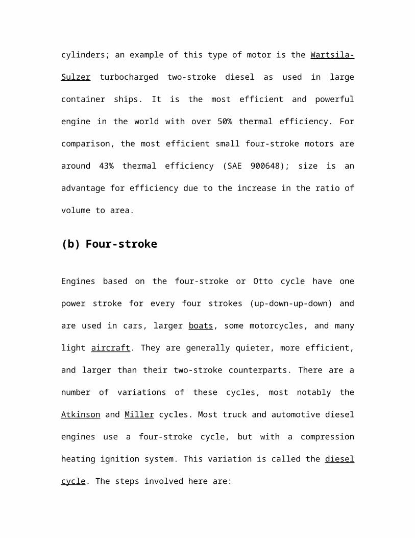
the cylinders; an example of this type of motor is the Wartsila-Sulzer turbocharged two-
stroke diesel as used in large container ships. It is the most efficient and powerful engine
in the world with over 50% thermal efficiency. For comparison, the most efficient small
four-stroke motors are around 43% thermal efficiency (SAE 900648); size is an
advantage for efficiency due to the increase in the ratio of volume to area.
(b) Four-stroke
Engines based on the four-stroke or Otto cycle have one power stroke for every four
strokes (up-down-up-down) and are used in cars, larger boats, some motorcycles, and
many light aircraft. They are generally quieter, more efficient, and larger than their two-
stroke counterparts. There are a number of variations of these cycles, most notably the
Atkinson and Miller cycles. Most truck and automotive diesel engines use a four-stroke
cycle, but with a compression heating ignition system. This variation is called the diesel
cycle. The steps involved here are:
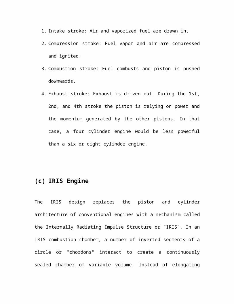
1. Intake stroke: Air and vaporized fuel are drawn in.
2. Compression stroke: Fuel vapor and air are compressed and ignited.
3. Combustion stroke: Fuel combusts and piston is pushed downwards.
4. Exhaust stroke: Exhaust is driven out. During the 1st, 2nd, and 4th stroke the
piston is relying on power and the momentum generated by the other pistons. In
that case, a four cylinder engine would be less powerful than a six or eight
cylinder engine.

(c) IRIS Engine
The IRIS design replaces the piston and cylinder architecture of conventional engines
with a mechanism called the Internally Radiating Impulse Structure or "IRIS". In an IRIS
combustion chamber, a number of inverted segments of a circle or "chordons" interact to
create a continuously sealed chamber of variable volume. Instead of elongating during
combustion—as a traditional engine does—the IRIS engines' chamber expands in
diameter. This innovation may significantly enhance fuel efficiency by reducing waste
heat and increasing the amount of surface area the engine has available to produce torque.
The IRIS design was recently patented and may eventually yield engines that are smaller,
lighter, and more efficient than traditional piston-based systems.
(d) Bourke engine
In this engine, two opposed cylinders are linked to the crank by a Scotch yoke. The
Scotch yoke mechanism prevents side thrust which in turn prevents any piston slap
allowing the operation as a detonation or "explosion" engine. This also greatly reduces
friction between pistons and cylinder walls. The Bourke engine uses fewer moving parts
and has to overcome less friction than conventional crank and slider engines with poppet
valves, however no independent testing of this engine has ever expanded any of these
claims.

(e) Controlled Combustion Engine
These are also cylinder-based engines, which may be one or two-stroke but instead of a
crankshaft and piston rods, use two gear-connected, counterrotating concentric cams to
convert reciprocating motion into rotary movement. These cams practically cancel out
sideward forces that would otherwise be exerted on the cylinders by the pistons greatly
improving mechanical efficiency. The number of lobes of the cams (always an odd
number not less than 3) determines the piston travel versus the torque delivered. In this
engine, there are two cylinders that are 180 degrees apart for each pair of counterrotating
cams. For single-stroke versions, there are as many cycles per cylinder pair as there are
lobes on each cam and twice as many for two-stroke engines.
(f) Wankel
The Wankel engine (rotary engine) does not have piston strokes so it is more properly
called a, "four-phase"—rather than a four-stroke engine. It operates with the same
separation of phases as the four-stroke engine with the phases taking place in separate
locations in the engine. While it is true that three power strokes typically occur per rotor
revolution due to the 3/1 revolution ratio of the rotor to the eccentric shaft, only one
power stroke per shaft revolution actually occurs; this engine provides three power
'strokes' per revolution per rotor giving it a greater power-to-weight ratio than piston
engines. This type of engine is most notably used in the current Mazda RX-8, the earlier
RX-7, and other models.

(g) Gas turbine
Gas turbine cycle engines employ a continuous combustion system where compression,
combustion, and expansion occur simultaneously at different places in the engine—
giving continuous power.
A gas turbine is a rotary machine similar in principle to a steam turbine and it consists of
three main components: a compressor, a combustion chamber, and a turbine. The air after
being compressed in the compressor is heated by burning fuel in it. About two-thirds of
the heated air combined with the products of combustion is expanded in a turbine
resulting in work output which is used to drive the compressor. The rest (about one-third)
is available as useful work output.
(h) Jet engine
Jet engines take a large volume of hot gas from a combustion process (typically a gas
turbine, but rocket forms of jet propulsion often use solid or liquid propellants) and feed
it through a nozzle which accelerates the jet to high speed. As the jet accelerates through
the nozzle, this creates thrust and in turn does useful work.
(I) Disused methods
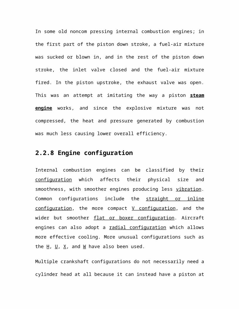
In some old noncom pressing internal combustion engines; in the first part of the piston
down stroke, a fuel-air mixture was sucked or blown in, and in the rest of the piston down
stroke, the inlet valve closed and the fuel-air mixture fired. In the piston upstroke, the

exhaust valve was open. This was an attempt at imitating the way a piston steam engine
works, and since the explosive mixture was not compressed, the heat and pressure
generated by combustion was much less causing lower overall efficiency.
2.2.8 Engine configuration
Internal combustion engines can be classified by their configuration which affects their
physical size and smoothness, with smoother engines producing less vibration. Common
configurations include the straight or inline configuration, the more compact V
configuration, and the wider but smoother flat or boxer configuration. Aircraft engines
can also adopt a radial configuration which allows more effective cooling. More unusual
configurations such as the H, U, X, and W have also been used.
Multiple crankshaft configurations do not necessarily need a cylinder head at all because
it can instead have a piston at each end of the cylinder called an opposed piston design.
This design was used in the Junkers Jumo 205 diesel aircraft engine, using at either end
of a single bank of cylinders with two crankshafts, and most remarkably in the Napier
Deltic diesel engines. These used three crankshafts to serve three banks of double-ended
cylinders arranged in an equilateral triangle with the crankshafts at the corners. It was
also used in single-bank locomotive engines, and continues to be used for marine
engines, both for propulsion and for auxiliary generators. The Gnome Rotary engine,
used in several early aircraft, had a stationary crankshaft and a bank of radially arranged
cylinders rotating around it.
2.2.9 Engine capacity
An engines' capacity is the displacement or swept volume by the pistons of the engine. It
is generally measured in liters (L) or cubic inches (c.i.d. or cu in or in³) for larger engines,

and cubic centimeters (abbreviated cc) for smaller engines. Engines with greater
capacities are usually more powerful and provide greater torque at lower rpm, but also
consume more fuel. Apart from designing an engine with more cylinders, there are two
ways to increase an engines' capacity. The first is to lengthen the stroke: the second is to
increase the pistons' diameter (See also: Stroke ratio). In either case, it may be necessary
to make further adjustments to the fuel intake of the engine to ensure optimal
performance.
2.2.10 Common components
(a) Combustion chambers
Internal combustion engines can contain any number of combustion chambers
(cylinders), with numbers between one and twelve being common, though as many as 36
(Lycoming R-7755) have been used. Having more cylinders in an engine yields two
potential benefits: first, the engine can have a larger displacement with smaller individual
reciprocating masses, that is, the mass of each piston can be less thus making a smoother-
running engine since the engine tends to vibrate as a result of the pistons moving up and
down: secondly, with a greater displacement and more pistons, more fuel can be
combusted and there can be more combustion events (more power strokes) in a given
period of time. This means that such an engine can generate more torque than a similar
engine with fewer cylinders.
The downside to having more pistons is that the engine will tend to weigh more and
generate more internal friction as the greater number of pistons rub against the inside of
their cylinders. This tends to decrease fuel efficiency and robs the engine of some of its
power. For high-performance gasoline engines using current materials and technology—

such as the engines found in modern automobiles, there seems to be a break-point around
10 or 12 cylinders after which the addition of cylinders becomes an overall detriment to
performance and efficiency. Although, exceptions such as the W16 engine from
Volkswagen exist.
Most car engines have four to eight cylinders with some high performance cars
having ten, twelve—or even sixteen, and some very small cars and trucks having
two or three. In previous years, some quite large cars such as the DKW and Saab
92, had two-cylinder or two-stroke engines.
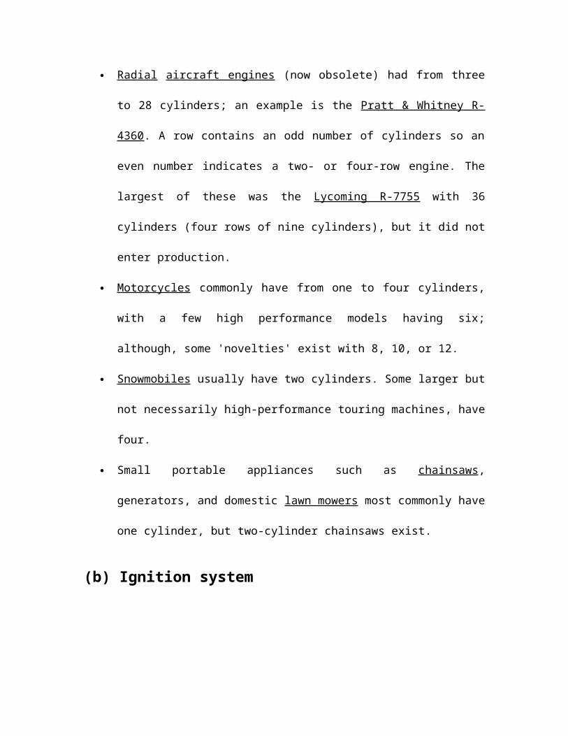
Radial aircraft engines (now obsolete) had from three to 28 cylinders; an example
is the Pratt & Whitney R-4360. A row contains an odd number of cylinders so an
even number indicates a two- or four-row engine. The largest of these was the
Lycoming R-7755 with 36 cylinders (four rows of nine cylinders), but it did not
enter production.
Motorcycles commonly have from one to four cylinders, with a few high
performance models having six; although, some 'novelties' exist with 8, 10, or 12.
Snowmobiles usually have two cylinders. Some larger but not necessarily high-
performance touring machines, have four.
Small portable appliances such as chainsaws, generators, and domestic lawn
mowers most commonly have one cylinder, but two-cylinder chainsaws exist.
(b) Ignition system
An internal combustion engine can be classified by its ignition system. Today most
engines use an electrical or compression heating system for ignition.

(1) Spark: The mixture is ignited by an electrical spark from a spark plug—the
timing of which is very precisely controlled. Almost all gasoline engines are of this type,
but not diesel engines.
(2) Compression: Ignition comes from the heat derived from oxidation and the
mechanical compression of the air or mixture. The vast majority of compression ignition
engines are diesels in which the fuel is mixed with the air after the air has reached
ignition temperature. In this case, the timing comes from the fuel injection system. Very
small model engines for which simplicity is more important than fuel costs, use special
fuels to control ignition timing.
(3) Ignition Timing: For reciprocating engines, the point in the cycle at which the
fuel-oxidizer mixture is ignited has a direct effect on the efficiency and output of the ICE.
The thermodynamics of the idealized Carnot heat engine tells us that an ICE is most
efficient if most of the burning takes place at a high temperature, resulting from
compression—near top dead center. The speed of the flame front is directly affected by
the compression ratio, fuel mixture temperature, and octane or cetane rating of the
fuel. Leaner mixtures and lower mixture pressures burn more slowly requiring more
advanced ignition timing. It is important to have combustion spread by a thermal flame
front (deflagration), not by a shock wave. Combustion propagation by a shock wave is
called detonation and, in engines, is also known as pinging or knocking.
So at least in gasoline-burning engines, ignition timing is largely a compromise between
an earlier "advanced" spark—which gives greater efficiency with high octane fuel—and a

later "retarded" spark that avoids detonation with the fuel used. For this reason, high-
performance diesel automobile proponents such as, Gale Banks, believe that
© Fuel systems
A device used to deliver fuel to the internal combustion engine. Fuels burn faster and
more completely when they have lots of surface area in contact with oxygen. In order for
an engine to work efficiently the fuel must be vaporized into the incoming air in what is
commonly referred to as a fuel-air mixture. There are two commonly used methods of
vaporizing fuel into the air: one is the carburetor: the other is fuel injection.
(1) Carburetor: Often for simpler reciprocating engines, a carburetor is used to supply
fuel into the cylinder. However, exact control of the correct amount of fuel supplied to
the engine is impossible. Carburetors are the current most widespread fuel mixing device
used in lawn mowers and other small engine applications. Prior to the mid-1980s,
carburetors were also common in automobiles.
(2) Fuel injection: Larger gasoline engines used in automobiles have mostly moved to
fuel injection systems (see Gasoline Direct Injection). Diesel engines always use fuel
injection because it is the fuel system that controls the ignition timing. Other internal
combustion engines like jet engines use burners and rocket engines use various different
ideas including impinging jets, gas/liquid shear, preburners, and many other ideas.

(d) Oxidizer-Air inlet system
Some engines such as solid rockets have oxidisers already within the combustion
chamber but in most cases for combustion to occur, a continuous supply of oxidiser must
be supplied to the combustion chamber.
(1) Natural aspirated engines: When air is used with piston engines it can simply suck
it in as the piston increases the volume of the chamber. However, this gives a maximum
of 1 atmosphere of pressure difference across the inlet valves, and at high engine speeds
the resulting airflow can limit potential power output.
(2) Superchargers: A supercharger is a "forced induction" system which uses a
compressor powered by the shaft of the engine which forces air through the valves of the
engine to achieve higher flow. When these systems are employed the maximum absolute
pressure at the inlet valve is typically around 2 times atmospheric pressure or more.
(e) Piston engine valves
In piston engines, the valves are grouped into 'inlet valves' which admit the entrance of
fuel and air and 'outlet valves' which allow the exhaust gases to escape. Each valve opens
once per cycle and the ones that are subject to extreme accelerations are held closed by
springs that are typically opened by rods running on a camshaft rotating with the engines'
crankshaft.

(f) Control valves
Continuous combustion engines—as well as piston engines—usually have valves that
open and close to admit the fuel and/or air at the startup and shutdown. Some valves
feather to adjust the flow to control power or engine speed as well.
(g) Exhaust systems
Internal combustion engines have to manage the exhaust of the cooled combustion gas
from the engine. The exhaust system frequently contains devices to control pollution,
both chemical and noise pollution. In addition, for cyclic combustion engines the exhaust
system is frequently tuned to improve emptying of the combustion chamber.
For jet propulsion internal combustion engines, the 'exhaust system' takes the form of a
high velocity nozzle, which generates thrust for the engine and forms a colimated jet of
gas that gives the engine its name.
(h) Cooling systems
Combustion generates a great deal of heat, and some of this transfers to the walls of the
engine. Failure will occur if the body of the engine is allowed to reach too high a
temperature, either the engine will physically fail, or any lubricants used will degrade to
the point that they no longer protect the engine.

Cooling systems usually employ air or liquid cooling while some very hot engines using
radiative cooling (especially some Rocket engines). Some high altitude rocket engines
use ablative cooling where the walls gradually erode in a controlled fashion.
(i) Piston
A piston is a component of reciprocating engines. It is located in a cylinder and is made
gas-tight by piston rings. Its purpose is to transfer force from expanding gas in the
cylinder to the crankshaft via a piston rod and/or connecting rod. In some engines, the
piston also acts as a valve by covering and uncovering ports in the cylinder wall.
(f) Crankshafts
Very many reciprocating internal combustion engines end up turning a shaft. This means
that the linear motion of a piston must be turned into a rotation. This is typically achieved
by a crankshaft.
Figure 2.4 A crankshaft for a 4 cylinder engine
(g) Flywheels
Flywheels are found in most reciprocating engines as a way to smooth out the power
delivery over each rotation of the crank. Without it, many engines would stall at low
engine speeds.
(h) Starter systems
Internal combustion engines require systems to put them into a operational mode that can
be sustained. For piston engines this can involve a starter motor; small portable engines
can be started with a manual crank or even pull cords.
(i) Lubrication Systems
Internal combustions engines require lubrication in operation to allow moving parts to
slide smoothly over each other. Insufficient lubrication will subject the engine to rapid
wear and ultimately, it may even seize up entirely.
Several different types of lubrication systems are used. Simple two-stroke engines are
lubricated by oil mixed into the fuel or injected into the induction stream as a spray. Early
slow-speed stationary and marine engines were lubricated by gravity from small
chambers similar to those used on steam engines at the time—with an engine tender
refilling these as needed. As engines were adapted for automotive and aircraft use, the
need for a high power-to-weight ratio led to increased speeds, higher temperatures, and
greater pressure on bearings which in turn required pressure-lubrication for crank
bearings and connecting-rod journals. This was provided either by a direct lubrication
from a pump, or indirectly by a jet of oil directed at pickup cups on the connecting rod
ends which had the advantage of providing higher pressures as the engine speed
increased
CHAPTER 3
A Mechanical Spring

3.1 Introduction to a spring
A spring is a flexible elastic object used to store mechanical energy. Springs are usually
made out of hardened steel. Small springs can be wound from pre-hardened stock, while
larger ones are made from annealed steel and hardened after fabrication. Some non-
ferrous metals are also used including phosphor bronze and titanium for parts requiring
corrosion resistance and beryllium copper for springs carrying electrical current (because
of its low electrical resistance).
Figure 3.1 Helical or coil springs designed for tension
The rate of a spring is the change in the force it exerts, divided by the change in
deflection of the spring. That is, it is the gradient of the force versus deflection curve. An
extension or compression spring has units of force divided by distance, for example lbf/in
or N/m. Torsion springs have units of force multiplied by distance divided by angle, such
as Nm/rad or ft lbf/degree. The inverse of spring rate is compliance that is if a spring has
a rate of 10 N/mm; it has a compliance of 0.1 mm/N. The stiffness (or rate) of springs in
parallel is additive, as is the compliance of springs in series.
3.2 Types of spring
(a) Depending on load they may be classified as:
Tension/Extension spring
Compression spring

Torsional spring
In tension/extension and compression there is axial load. On the other hand in the
torsional spring there is torsional force.
Figure 3.2 A spiral hair spring
(b) Depending on spring material it can be classified as:
Wire/Coil spring
Flat spring
(c) The most common types of spring are:
Cantilever spring - a spring which is fixed only at one end.
Coil spring or helical spring - a spring (made by winding a wire around a
cylinder) and the conical spring - these are types of torsion spring, because the
wire itself is twisted when the spring is compressed or stretched.
Compression springs are designed to become shorter when loaded. Their turns are
not touching in the unloaded position, and they need no attachment points.
A volute spring is a compression spring in the form of a cone, designed so that
under compression the coils are not forced against each other, thus permitting
longer travel.
Tension springs are designed to become longer under load. Their turns are
normally touching in the unloaded position, and they have a hook, eye or some
other means of attachment at each end.

Figure 3.3 Vertical volute springs of Stuart tank
Hairspring or balance spring - a delicate spiral torsion spring used in watches,
galvanometers, and places where electricity must be carried to partially-rotating
devices such as steering wheels without hindering the rotation.
Leaf spring - a flat springy seat, used in vehicle suspensions, electrical switches,
bows.
Figure 3.4 Leaf spring on a truck
V-spring - used in antique firearm mechanisms such as the wheellock, flintlock
and percussion cap locks.
Belleville washer or Belleville spring - a disc shaped spring commonly used to
apply tension to a bolt (and also in the initiation mechanism of pressure-activated
landmines).
Gas spring - a volume of gas which is compressed.

Ideal Spring - the notional spring used in physics: it has no weight, mass, or
damping losses.
Mainspring - a spiral ribbon shaped spring used as a power source in watches,
clocks, music boxes, windup toys, and mechanically powered flashlights.
Torsion spring - any spring designed to be twisted rather than compressed or
extended. It used in torsion bar vehicle suspension systems.
Negator spring - a thin flat metal band that is coiled similar to a tape rule. This
type of spring produces a constant force throughout a long displacement.
Wave spring - a high stiffness spring
3.3 Torsion spring
A torsion spring is a spring that works by torsion or twisting; that is, a flexible elastic
object that stores mechanical energy when it is twisted. The amount of force (actually
torque) it exerts is proportional to the amount it is twisted. A torsion spring is often made
from a wire, ribbon, or bar of metal or rubber, while more delicate ones are made of silk,
glass, or quartz fibers.
(a) Torsion coefficient
As long as they are not twisted beyond their elastic limit, torsion springs obey an angular
form of Hooke's law. It is analogous to the spring constant of a linear spring.
(b) Uses
Torsion bars (or sway bars) are heavy torsion springs used to support automobile
suspension components, allowing those components (which indirectly support the
wheels) to move in response to rough roads while allowing a smooth ride in the
vehicle.
The torsion pendulum used in torsion pendulum clocks is a wheel-shaped weight
suspended from its center by a wire torsion spring. The weight rotates about the
axis of the spring, twisting it, instead of swinging like an ordinary pendulum. The
force of the spring reverses the direction of rotation, so the wheel oscillates back
and forth, driven at the top by the clock's gears.
The torsion catapult is a medieval siege engine invented by the ancient Greeks. It
uses a torsion spring consisting of twisted ropes to swing an arm that throws a
heavy missile at the enemy with great force.
The balance spring or hairspring in mechanical watches is a fine spiral-shaped
torsion spring that pushes the balance wheel back toward its center position as it
rotates back and forth. The balance wheel and spring function similarly to the
torsion pendulum above in keeping time for the watch.
3.4 Leaf spring
It is originally called laminated or carriage spring, a leaf spring is a simple form of
spring, commonly used for the suspension in wheeled vehicles. It is also one of the oldest
forms of springing, dating back to medieval times.
Sometimes referred to as a semi-elliptical spring or cart spring, it takes the form of a
slender arc-shaped length of spring steel of rectangular cross-section. The center of the
arc provides location for the axle, while tie holes are provided at either end for attaching
to the vehicle body. For very heavy vehicles, a leaf spring can be made from several
leaves stacked on top of each other in several layers, often with progressively shorter
leaves. Leaf springs can serve locating and to some extent damping as well as springing
functions.
Figure 3.6 A leaf spring is connected to the frame through a shackle

A leaf spring can either be attached directly to the frame at both ends or attached directly
at one end, usually the front, with the other end attached through a shackle, a short
swinging arm. The shackle takes up the tendency of the leaf spring to elongate when
compressed and thus makes for softer springiness.
3.5 Coil spring
A Coil spring, also known as a helical spring, is a mechanical device, which is typically
used to store energy and subsequently release it, to absorb shock, or to maintain a force
between contacting surfaces. They are made of an elastic material formed into the shape
of a helix which returns to its natural length when unloaded.
Figure 3.7 A compression coil spring
Figure 3.8 A tension coil spring
Coil springs are a special type of torsion spring, the material of the spring acts in torsion
when the spring is compressed or extended. The two usual types of coil spring are:
Tension coil springs which are designed to resist stretching. They usually have a
hook or eye form at each end for attachment.
Compression coil springs are designed to resist being compressed. A typical use
for compression coil springs is in car suspension systems.
3.6 Hooke's law

Most springs (not stretched or compressed beyond the elastic limit) obey Hooke's law,
which states that the force with which the spring pushes back is linearly proportional to
the distance from its equilibrium length.
Coil springs and other common springs typically obey Hooke's law. There are useful
springs that don't: springs based on beam bending can for example produce forces that
vary nonlinearly with displacement.
There are also linear springs which don't follow Hooke's law: a Negator spring (the
spring that a self retracting tape measure uses) provides a constant force.
3.7 Theory
In classical physics, a spring can be seen as a device that stores potential energy by
straining the bonds between the atoms of an elastic material. Hooke's law of elasticity
states that the extension of an elastic rod (its distended length minus its relaxed length) is
linearly proportional to its tension, the force used to stretch it. Similarly, the contraction
(negative extension) is proportional to the compression (negative tension). This law
actually holds only approximately, and only when the deformation (extension or
contraction) is small compared to the rod's overall length. For deformations beyond the
elastic limit, atomic bonds get broken or rearranged, and a spring may snap, buckle, or
permanently deform. Many materials have no clearly defined elastic limit, and Hooke's
law can not be meaningfully applied to these materials. Hooke's law is a mathematical
consequence of the fact that the potential energy of the rod is a minimum when it has its
relaxed length. Any smooth function of one variable approximates a quadratic function
when examined near enough to its minimum point; and therefore the force, which is the
derivative of energy with respect to displacement, will approximate a linear function.
3.8 Uses
Vehicle suspension
Slinky
Pogo Stick
Dashpot

CHAPTER 4
Designing of Shock Absorber
4.1 Design of Shock Absorber for automobile
The research project is carried out for Maruti-Van car, where two shock absorbers are
fixed on the front face of vehicle. Figure 4.1 shows the model of project in details. Shock
absorbers work on the principle of spring energy power and simply classified as
hydraulic compression close coil spring. The project model is designed for Maruti-Van
car.
4.1 Specification of components used
Shock absorbers:
No.: Two
Capacity: Depends on the vehicle type (for Maruti-Van, 500 Kg each)
Type: Hydraulic
Principle of operation: Spring energy
Weight:
Depend on vehicle type (for Maruti-Van, 30 Kg)
Cost:
30,000/- for Maruti-Van
4.2 Principle of operation
Both hydraulic springs are fixed on the front face of the vehicle as shown in figure 4.1. A
frame is also fixed on the shock absorbers. When vehicle will get collision with another
vehicle, an impact loading will apply to the frame and transfer to shock absorbers and
damage will be defiantly very less to the vehicle and also to the passengers.
The system works on the principal of momentum transfer ( Newton's laws of motion).
Newton's laws of motion describe the acceleration of massive particles. In modern
language, the laws may be stated as:

First law:
It is possible to select a set of reference frames, called inertial reference frames,
observed from which a particle moves without any change in velocity if no net
force acts on it. This law is often simplified into the sentence "A particle will stay
at rest or continue at a constant velocity unless acted upon by an external
unbalanced net force."
Second law:
Observed from an inertial reference frame, the net force on a particle is
proportional to the time rate of change of its linear momentum: F = d (mv) / dt.
Momentum mv is the product of mass and velocity. Force and momentum are
vector quantities and the resultant force is found from all the forces present by
vector addition. This law is often stated as "F = ma: the net force on an object is
equal to the mass of the object multiplied by its acceleration."
Third law:
Whenever a particle A exerts a force on another particle B, B simultaneously
exerts a force on A with the same magnitude in the opposite direction. The strong
form of the law further postulates that these two forces act along the same line.
This law is often simplified into the sentence "Every action has an equal and
opposite reaction."
4.3 Spring design
Two open coil helical spring of high stiffness is used in model to absorb the impact force
on the face of vehicle.
We know that:δ= (64 WR3n) / (Cd4)
Where:δ= Deflection of spring (30 cm in present case)W= Axial Load i.e. force required to compress the spring
R= Mean radius of spring coil (25 cm)
n= No. of turns (10)
C= Modulus of rigidity (1000 GPa) i.e. material has very high stiffness

d= Diameter of spring wire (5 cm)
By using the above data for the spring and above equation, W will be:
W=187500 N
Energy stored by one spring = W X δ /2
=28125 N-m
i.e. during the collision one spring can store the 28125 N-m energy or energy stored by
two spring will be 56250 N-m energy.
Now suppose during the collision the mass of two vehicles is 1000 Kg, and the relative
velocity is V m/s then kinetic energy will be generated:
K.E. = M X V2/2
Where:
M is mass of vehicles in Kg
V is relative velocity of vehicle
If whole kinetic energy is stored as spring energy then:
M X V2/2=56250 N-m
Since M=1000 Kg
i.e. V=10.61 m/s or 38.183 Km/hr
Hence we can say if two small vehicles are moving with a relative velocity of 38.18
Km/hr, then during collision whole kinetic energy will store as spring energy by this
arrangement and there will be no loss to the passengers and vehicle.
If both vehicles have this system of shock absorber then there will be no loss during the
collision even they have the relative velocity of 76.36 km/hr.
Vehicle can be made more safer by using more springs or shock absorber.
4.4 Designing of the driver’s seat
The design of the driver’s seat is also modified. When vehicle will get collision with
another vehicle, an impact loading will apply to the shock absorbers and driver’s seat will

move to down direction by the amount of deflection in spring. This arrangement is made
by leavers in model.
The linkage mechanism is used to get this arrangement.
This will help to driver with front loading and glass. The steering effect at this moment
will also be negligible, since driver will move to downwards direction. This arrangement
will helpful to save the life of driver during the collision of small vehicle with heavy
vehicles.

CHAPTER 5
Application, Advantages & Disadvantages

5.1 Applications
The system can be incorporate in any type of motor vehicle such as:
In small cars
In heavy loading vehicle like trucks and buses
The system can be useful for following type of car crash also.
.
Figure 5.1 A car crash
5.2 Advantages
1. Passenger safety will increase.
2. Pregnant women can continue journey.
3. As car safety is generally designed for normal sized adults. Safety features that
could save an adult can actually cause more damage to a child than if the feature
was not there.
4. Toddlers over 1 year old and between 10 and 20 kg (20 and 40 pounds) can make
journey.
5. Design is safe for young children also.
6. Teenage drivers will drive the vehicle very safely.
7. This system can wear up to 1000 Kg of impact loading. The capacity can be
increase by using more powerful shock absorbers.
8. Driver will be safe during the sudden crash or collision by modifying the seat
design.

9. The leaver of seat is connected to shock absorbers; movement of seat will also
depend on the displacement of frame (shock absorbers).
10. This system will turn out highly safe driving for single person, who drives the
vehicle.
11. Car safety will also increase, since there will be less damage after crashing.
5.2 Disadvantages
1. Cost will increase slightly.
2. Weight of vehicle will increase slightly.
3. System required maintenance also.
4. Looks of vehicle will change.
CHAPTER 6
Future scope and conclusion

6.1 Future scope
The arrangement is designed for small car in this project work, but this arrangement can
be widely use in future for heavy vehicles also by making some small modifications in
current project.
6.2 Conclusion
A car accident is a road traffic incident which usually involves one road vehicle colliding
with, another vehicle, another road user, or a stationary roadside object, and which may
result in injury or property damage.
Frontal impacts are most common accidents in the world of automobile, and this system
will be very useful and helpful to mange these type of accidents, since, an inbuilt shock
absorber system on front face of a car can be easily attached to all currently manufacture
automobile companies.
The system works on the principal of spring energy and design with the help of two
hydraulic open coil compression springs.
This arrangement has many advantages such as saving of life and vehicle saving. With
the help of this system the driving of vehicles will be easy especially for ladies.
Arrangement is also very useful for heavy loading vehicles and a single person can go on
a fearless long drive. Single and both shock absorbers can work simultaneously at a
single time also i.e. arrangement will be useful to frontal and as well side collision also.
References:
1. www.howstuffworks.com .
2. www.google.com .
3. www.bharatwirerope.com .
4. www.wikipedia.com.
5. www.rope-making.com.
6. www.vikrantropes.com.
7. www.finolex.com.
8. www.techsourcer.com.
9. www.engineering.com.
10. www.globalspec.com.
11. www.irational.org.
12. www.safetysling.com.
13. www.aboutconstruction.org.
14. www.encarta.com.
15. www.britannica.com .
16. A Textbook of Machine Design by R.S.Khurmi & J.K.Gupta.
17. A Textbook of Automobile Engineering by Dr. Kirpal Singh.