major review - university of southern california prosthesis for the blind.pdf · retinal prosthesis...
TRANSCRIPT

335
MAJOR REVIEW
SURVEY OF OPHTHALMOLOGY
VOLUME 47
•
NUMBER 4
•
JULY–AUGUST 2002
© 2002 by Elsevier Science Inc. 0039-6257/02/$–see front matterAll rights reserved. PII S0039-6257(02)00311-9
Retinal Prosthesis for the Blind
Eyal Margalit, MD, PhD,
1
Mauricio Maia, MD,
1
James D. Weiland, PhD,
1
Robert J. Greenberg, MD, PhD,
2
Gildo Y. Fujii, MD,
1
Gustavo Torres, MD,
1
Duke V. Piyathaisere, BS,
1
Thomas M. O’Hearn, BS,
1
Wentai Liu, PhD,
3
Gianluca Lazzi, PhD,
3
Gislin Dagnelie, PhD,
1
Dean A. Scribner, PhD,
4
Eugene de Juan Jr, MD,
1
and Mark S. Humayun, MD, PhD
1
1
Intraocular Prosthesis Group, Wilmer Eye Institute, Johns Hopkins, Baltimore, Maryland;
2
Second Sight LLC, Valencia, California;
3
Department of Electrical and Computer Engineering, North Carolina State University,Raleigh, North Carolina; and
4
Naval Research Laboratory, Washington, DC, USA
Abstract.
Most of current concepts for a visual prosthesis are based on neuronal electrical stimulationat different locations along the visual pathways within the central nervous system. The different designsof visual prostheses are named according to their locations (i.e., cortical, optic nerve, subretinal, andepiretinal). Visual loss caused by outer retinal degeneration in diseases such as retinitis pigmentosa orage-related macular degeneration can be reversed by electrical stimulation of the retina or the opticnerve (retinal or optic nerve prostheses, respectively). On the other hand, visual loss caused by inner orwhole thickness retinal diseases, eye loss, optic nerve diseases (tumors, ischemia, inflammatory pro-cesses etc.), or diseases of the central nervous system (not including diseases of the primary and sec-ondary visual cortices) can be reversed by a cortical visual prosthesis. The intent of this article is toprovide an overview of current and future concepts of retinal and optic nerve prostheses. This articlewill begin with general considerations that are related to all or most of visual prostheses and then con-centrate on the retinal and optic nerve designs. The authors believe that the field has grown beyondthe scope of a single article so cortical prostheses will be described only because of their direct effect onthe concept and technical development of the other prostheses, and this will be done in a more generaland historic perspective.. (
Surv Ophthalmol 47
:335–356, 2002. © 2002 by Elsevier Science Inc. Allrights reserved.)
Key words.
artificial vision
•
blindness
•
cortical prosthesis
•
electrical stimulation
•
electronic implants
•
macular degeneration
•
optic nerve
•
optic nerve prosthesis
•
retina
•
retinal prosthesis
•
retinitis pigmentosa
•
visual cortex
•
visual prosthesis
More than 1 million Americans are legally blind andapproximately 10% have no light perception from allcauses. Hereditary retinal degeneration and age-re-lated macular degeneration are two examples ofblinding retinopathies,
124
for which there are only afew ways to prevent or halt the development of blind-ness. Photodynamic or conventional laser therapy are
two methods that can be effective in treating age-re-lated macular degeneration,
13
and gene therapy anddrug therapy are two examples of experimental ap-proaches to prevent the development of blindnesscaused by retinal diseases.
10,135
There is also a limitednumber of experimental treatments, which can theo-retically reverse visual loss: for example, gene therapy

336 Surv Ophthalmol 47 (4) July–August 2002
MARGALIT ET AL
for retinal degeneration,
1
or retinal transplantationfor different retinal diseases.
39
Visual prosthesis is an-other way with which several research groups hope torestore useful vision to blind patients.
One of the most important questions regarding vi-sual prostheses is if an electrical stimulation of a smallarea of neuronal tissue in the visual pathways will cre-ate light perception that is comparable to that createdby light stimulation of retinal photoreceptors. The vi-sual cortex was the first target for the visual prosthesisengineering efforts. Foerster, a German neurosur-geon, noted that electrical stimulation of the visualcortex caused his subject to see a spot of light (phos-phene). The spatial psychophysical location of thephosphene depended on the location of electricalstimulation spot over the cortex.
49
Others followedwith similar results at different locations of the visualpathways, including the visual cortex, the optic nerve,and the retina (Table 1).
16,25,43,70,117,130,153
So, the answerto the first part of the question was yes, we can stimu-late a small area of neuronal tissue and get a light per-ception, but the answer to second part was no, it is notcomparable to light stimulation. The phosphene isseen usually as a white, round, or oval point of light,and it has different sizes. We describe these results inmuch more detail later in this article. Other importantquestions are related to whether a whole visual imagecan be created by stimulation of many small areas ofneuronal tissue (pixels), how many pixels are requiredfor such an image, and what are the electrical stimulusparameters (amplitude, duration, shape etc.) neededfor each pixel to make it safe and effective.
I. General Considerations
A. EFFICACY OF A VISUAL PROSTHESIS
1. Psychophysical Experiments
There is a general consensus that electrical stimula-tion of the visual pathways via a small number of elec-trodes cannot be expected to provide unaided under-
standing of visual information. In an effort to definethe minimum acceptable resolution for useful vision,several psychophysical experiments were performed.As early as 1965, it was suggested that 600 points ofstimulation (pixels) would be sufficient for readingordinary print.
14
Others suggested that 80–120 pointsare sufficient for large-print reading, while 200 pointsmay allow recognition of simple obstacles.
139
More recent studies of simulated pixelized visionshowed that 625 points of stimulation is a better esti-mate for certain tasks.
26–28
These studies were con-ducted with a portable phosphene simulator, whichconsisted of a small head-mounted video camera anda monitor worn by a normally sighted human subject.To simulate a discrete phosphene field, an opaqueperforated film masked the monitor. The visual anglesubtended by images from the masked monitor was1.7
�
or less, depending on the mask, and fell withinthe fovea of the subject. It was concluded that 625electrodes implanted in a 1cm
2
area near the fovealrepresentation of the visual cortex could produce aphosphene image with a visual acuity of approxi-mately 20/30. Such acuity could provide useful resto-ration of functional vision for the profoundly blind.
26
In another experiment, using the same methods,the reading speed was measured in subjects viewingpixelized text. The results indicated that a 25
�
25pixel array representing four letters of text is suffi-cient to provide reading rates near 170 words/minute with scrolled text, and near 100 words/minute with fixed text.
28
The feasibility of achieving visually guided mobil-ity was investigated with a similar device. Normallysighted human subjects were required to walkthrough a maze that included a series of obstacles.The results indicated again that 625 pixels provideduseful visually guided mobility. Walking speed in-creased 5-fold during 3 weeks of training.
27
To make a cortical electrode array of 600 or morechannels, several methods were proposed. Consider-
TABLE 1
Experimental Results of Visual Stimulators That Were Implanted in Human Subjects at Different Locations of the Visual System
ReferenceType of
StimulationSpatial
Orientation PatientsReadingLetters
Localizationof an ExternalLight Source
Time ofImplant
Number ofElectrodes
70,71 Epiretinal
�
Blind fromRP and AMD
�
Acute 1–25
157 Epiretinal
�
Laser ablatedretinas
Acute 1
153 Optic nerve
�
Blind from RP Chronic 4
98 Subretinal Not published Blind from RP Not published Not published Chronic 3,500
RP
�
retinitis pigmentosa; AMD
�
age-related macular degeneration.

RETINAL PROSTHESIS FOR THE BLIND
337
ing the visual cortex’s mean extent of 9.7 cm
2
, thenumber of electrodes that can be inserted, usingcurrent technologies, can reach 10,000 or more, as-suming that methods can be developed for elec-trode placement in cortical sulci and at the medialwall of the occipital hemispheres.
75
Although these studies began to delineate thenumber of electrodes needed, the fact that all thepixels were projected on a very small area of the ret-ina made it impractical to translate to a design of aretinal prosthesis, in which the electrodes would bespread over the entire macular region. Thus, a lowvision enhancement system (LVES) has been modi-fied to filter images on a head-mounted display inorder to simulate pixelized prosthetic vision and toproduce an array of dots. The results suggested thata fair level of visual function can be achieved for fa-cial recognition and reading large-print text usingpixelized vision parameters such as 25
�
25 grid in a10
�
field, with high contrast imaging and 4 or moregray levels.
37
It was reported recently that a blind volunteer with a20-year-old electrode implant on the visual cortex sur-face is now able to navigate, perform simple tasks,count fingers and identify large print letters (corre-sponding to a visual acuity of approximately 20/1200).The implant includes 8
�
8 electrodes, many of theminactive. These abilities were acquired after a longperiod of training.
42
Early and current experimentswith the cochlear implant demonstrated that electri-cal stimulation with only 4–8 input channels allows deafpatients to hear and even talk over the phone.
35,41,160
Perhaps a similar phenomenon (redundancy in vi-sual information) and the plasticity of the visual systemwill permit fewer retinal or cortical stimulating elec-trodes (compared to the estimated number of 600electrodes), to give blind patients some useful vision.
In spite of these interesting experiments, there aremajor issues on the way to predict the correct num-ber of channels needed for functional vision. Someof them are related to the facts that visual prosthesisphosphenes may be of variable size, may show vary-ing persistence, or may interact with each other. Also,there might be multiple phosphenes induced by thesame electrode.
43,130
Most of these problems were en-countered during cortical electrical stimulation, but thatis most probably because more human experimentswere performed at this anatomical location. How-ever, it could be related to the fact that the higherone is at the visual pathway hierarchy, the less pre-dictable the response becomes after bypassing sev-eral processing stations.
In the case of the cochlear prosthesis, psychophys-ical experiments have been of limited value in pre-dicting the function of the cochlear implant. Untilactual devices are implanted and tried extensively,
one should suspect that the same might be true ofthe visual prosthesis.
2. Neuronal Electrical Excitation
a. Threshold Parameters for Electrical Stimulation
Hodgkin and Huxley used the voltage clamp tech-nique in the squid axon to give the first complete de-scription of the ionic mechanisms underlying the ac-tion potential of neurons.
67,68
According to theHodgkin–Huxley model, an action potential in-volves the following sequence of events. A depolar-ization of the membrane causes Na+ channels toopen rapidly resulting in an inward Na+ current (be-cause of a higher concentration of this ion outsidethe cell membrane). This current, by dischargingthe membrane capacitance, causes further depolar-ization, thereby opening more Na+ channels, result-ing in increased inward current. This regenerativeprocess causes the action potential. The depolariza-tion state of the action potential then limits the du-ration of the action potential in two ways: 1) it grad-ually inactivates the Na+ channels, and 2) it opensthe voltage gated K+ channels with some delay. Con-sequently, the inward Na+ current is followed by anoutward K+ current that tends to repolarize themembrane current (because of a higher concentra-tion of this ion inside the cell membrane). Otherconclusions from Hodgkin and Huxley experimentswere the following: 1) the basic mechanism of actionpotential generation is the same in all neurons; 2)the nervous system expresses a large variety of volt-age-gated ion channels (i.e., Ca+ channels); 3) gat-ing of voltage-sensitive channels can be influencedby intracellular ion concentrations (i.e., Ca+ ions);4) excitability properties vary among neurons mainlybecause of the variety of ion channels properties;and 5) excitability properties vary within regions ofthe neuron (i.e., axon vs. dendrites). The Hodgkin–Huxley model (equation) has been derived by fittinganalytic curves to empirical data from the squid axon.
Electrical stimulation elicits a neural response byopening the voltage-sensitive ion channels and by-passing the chemically gated channels in the stimu-lated cell. Once the membrane reaches a certain po-tential, a trigger mechanism is released and anaction potential results (all-or-none mechanism).Many of the works studying models for electricalstimulation of neurons use the Hodgkin–Huxleyequations.
8,99
These works studied the effect of dif-ferent parameters on neuronal excitation threshold.The threshold is the minimum electrical stimulusamplitude and duration required for initiating anaction potential. It is essential to determine the mostefficient electrical stimulation parameters (i.e., pulseamplitude, pulse duration, pulse repetition, waveshape, pulse polarity, etc.—see below) and electrode

338 Surv Ophthalmol 47 (4) July–August 2002
MARGALIT ET AL
array properties for getting the lowest threshold pos-sible. Such low stimulation threshold will enable anefficient design for any visual prosthesis, becausethese characteristics will determine how many chan-nels of stimulation will be available, how muchpower will be necessary, and what mechanical prop-erties will specify the device.
A number of factors can influence the efficacy ofelectrical stimulation. First, the threshold depends onthe electrical properties and anatomy of the targetneural elements, and what portion of the cell (den-drite, cell body, and axon) is stimulated. For example,myelinated axons are more easily stimulated then un-myelinated ones.
114
Consequently, one computationalmodel of extracellular field stimulation of the retinalganglion cell (RGC) has shown that even though theaxon is closer to an epiretinal stimulating electrode,the extracellular stimulation threshold of the RGCsoma is 58–73% lower than its axon.
55
Second, the threshold is obviously affected by thedistance from the electrodes to the target cell.Smaller distances from the target require less electri-cal energy for stimulation.
8
Third, the threshold dur-ing bipolar stimulation is also affected by the pulseduration.
54,136
Fourth, threshold can vary significantlydue to the impedance of tissues and errors can be as-sociated with the assumption that tissue electricalproperties are the same in every stimulated compart-ment (homogenous and isotropic tissue properties),especially with bipolar electrical stimulation.
143
Fifth, there is a well-defined relationship betweenthe threshold current/charge and stimulus pulse du-ration required for neuronal activation.
11,58,158
As thepulse duration decreases, the threshold current in-creases. This relationship begins to break down atthe extremes (i.e., a very short current pulse cannotactivate a nerve regardless of the amplitude). Simi-larly, as the pulse duration increases, the thresholdcurrent approaches a minimum value called therheobase, below which an action potential cannot beelicited regardless of pulse duration. This currentlevel can be interpreted as a “leakage” current thatcan pass through the tissue without inducing depo-larization. The chronaxie of a neuron is defined as apulse width for which the threshold current is twicethe rheobase current.
113
Charge, which accounts forboth the pulse amplitude and pulse duration, isprobably the most meaningful parameter for electri-cal stimulation because of damage considerations toelectrodes and tissue (see section Threshold Param-eters for Electrical Stimulation).
91,92,94
This is be-cause electrode materials can withstand only certaincharge density before irreversible toxic reactions oc-cur at the electrode tissue interface. Charge and cur-rent have different minimum requirements duringneuronal stimulation. A minimum charge is re-
quired for shorter pulse duration in contrast to cur-rent, which is minimized at longer pulse duration.
122
However, unlike electrical stimulation of other ner-vous system cells, the optimum pulse duration maynot be short in the retina because graded potentialcells have longer chronaxies than other excitableneurons.
54
Sixth, in addition to current amplitude, charge,and pulse duration, investigators found that thresh-old is affected by the repetition rate of stimuli in thecortex and optic nerve.
130,153
In one of the corticalstimulation experiments the threshold was constantat frequencies of 150–200 Hz and increased 50% at75Hz.
130
Furthermore, in the cortex, it was found thatonly those pulses delivered in the first 100 ms woulddetermine the sensory response for trains of stimuluspulses at any specified set of parametric values.
64
Seventh, the polarity of electrical stimulation isalso an important factor. Neurons can be activatedby cathodic threshold activation, anodic pulses andbiphasic pulses.
53,118
In many neural systems, highercurrents were required to reach threshold with an-odic stimulation compared to cathodic stimulation,so cathodic stimulation is considered the preferredpolarity for most of the visual prostheses.
113
Biphasicwaveform can have either a cathodic or anodic wavefirst. However, for most applications, cathodic firstbiphasic pulses result in lower thresholds, presum-ably because they depolarize the cell membraneclosest to the electrode.
82
The two phases of the bi-phasic pulse are used for charge balancing and thusavoiding irreversible reactions at the tissue electrodeinterface, which in its extensive form can result inelectrolysis and significant pH changes as well aselectrode metal deposition into tissue. The twophases can have equal amplitudes and pulse durationbut can also be asymmetric with a phase having loweramplitude but longer duration in order to result incharge balance.
118
In a series of patients who under-went epiretinal electrical stimulation there was no dif-ference between monopolar versus bipolar stimula-tion and cathodic versus anodic first stimulation.
70
Eighth, another variable for threshold stimulationis the waveform. Two basic waveforms have beenused frequently for neural stimulation: sinusoidaland pulsatile (square) waveforms. There are manyvariants of these basic waveforms that can be usedfor different purposes. The most frequently used isthe pulsatile (square) waveform.
120
Having reviewed the variables involved in electri-cal stimulation of neurons, we will now summarizethe different threshold values found for electricalstimulation of several points along the visual path-ways (not including the visual cortex). These valuesare presented in Tables 2 and 3. It should be notedthat these studies were performed in different spe-

RETINAL PROSTHESIS FOR THE BLIND
339
cies, at different electrophysiological sites, using dif-ferent electrode sizes, and with different stimulus pa-rameters (pulse repetition rate, pulse duration,waveforms, train lengths, etc.). The threshold was ei-ther measured by physiological methods (recordingevoked potentials or single neuron responses fromRGC) or by psychophysical responses (phospheneperception in humans). Thus, these results can onlygive an estimate of electrical stimulation threshold
values of various locations along the visual systemand only a few conclusions can be drawn as to opti-mal methods to be used during electrical stimula-tion. It is clear the in vitro electrophysiologicalthreshold is lower than the in vivo electrophysiologi-cal and psychophysical thresholds.
59,65,69
This dis-crepancy is most probably due to the fact that the vi-sual system cannot recognize the activity of a singleor even a small number of neurons. If this is the case,
TABLE 2
Threshold Electrical Stimulation Parameters That Were Used by Different GroupsDuring In Vivo Experiments
Reference
Epiretinal stimulationparameters
117
Rabbits, extradural recording, current threshold 105–720
�
A, PD 100
�
sec, electrode diameter 40
�
m, charge density threshold 0.8–5.7 mC/cm
2
. Determination of threshold was done by repeating the stimulation and recording at different anatomical positions.
71 RP and AMD patients, current threshold 500
�
A, PD 2 ms, charge density threshold 0.16–70 mC/cm
2
, (1
�
C/phase)
70
. Determination of threshold by counting the electrical stimuli with varying frequencies of stimulation.
157 Laser treated human retinas, current threshold 100–600
�
A, charge threshold 0.1–0.6
�
C, charge density threshold 0.8–4.8 mC/cm
2
. Determination of threshold by counting the electrical stimuli with varying frequencies of stimulation.
Subretinal stimulationparameters
30 Normal rabbits cortical recordings), electrode surface area 0.36 cm
2
, charge density threshold 2.8–100 nC/cm
2
. Determination of threshold was done by reversing the input leads.
Optic nerve stimulationparameters
153 RP patient, current threshold 30
�
A, PD 400
�
sec, electrode area 0.2 mm
2
, repetition rate 160 Hz charge density threshold 24
�
C/cm
2
/pulse. Determination of threshold by two-staircase limit method.
RP
�
retinitis pigmentosa; AMD
�
age-related macular degeneration; PD
�
pulse duration.Human Experiments Are Bolded
TABLE 3
Threshold Electrical Stimulation Parameters That Were Used by Different Groups During In Vitro Experiments
Reference
Epiretinal stimulation parameters69 Charge density thresholds (using Pt electrodes): 2.98
�
C/cm
2
(bullfrog), 8.92 �C/cm2 (normal rabbit), 11.9 �C/cm2 (chemically RD rabbit). Determination of threshold was not mentioned.
59 Rabbit isolated retina, electrode diameter 10 �m, PD 400 �sec, threshold current 0.06–1.8 �A, threhsold charge density 30–917 �C/cm2. Determination of threshold was done by counting only response waveforms with ten or more sample points and by using synaptic transmission blockage.
Subretinal stimulation parameters141 Chick isolated retina, current threshold 35 �A, PD 0.4 ms, electrode surface area 0.01 mm2,
charge threshold 14 nC/phase, charge density threshold 178 �C/cm2. Determination of threshold was not mentioned. Determination of threshold was done by control with light stimulation and by using synaptic transmission blockage.
140 Retinal degenerate rates (RCS) isolated retina, charge density threshold 500 �C/cm2.Determination of threshold was not mentioned.
RP � retinitis pigmentosa; AMD � age-related macular degeneration; PD � pulse duration.

340 Surv Ophthalmol 47 (4) July–August 2002 MARGALIT ET AL
the exact number of stimulated neurons for in vivopsychophysical thresholds should be determined.
3. Electrodes
The electrodes’ charge transfer efficiency will af-fect every subsystem of the prosthesis by influencingthe power requirements and the electrode density.
Different materials were tested for the fabricationof electrode arrays. Even the precious metals (plati-num, iridium, rhodium, gold, and palladium) cor-rode under certain conditions of electrical stimula-tion.96 Platinum and its alloys with iridium are themost widely used for neural stimulating electrodes,due to its resistance to corrosion and considerablecharge carrying capacity. The unavoidable dissolu-tion of platinum under electrical stimulation de-creases when a protein is included in the solutionand with continuous stimulation.119
Iridium oxide (IrOx) electrodes belong to a newcategory termed “valence change oxides.” IrOx hasbeen used in research for nearly 20 years, but notcommercially. IrOx is exceptionally resistant to cor-rosion. The conservative charge density limit forchronic stimulation is 1 mC/cm2 and it has a safestimulation limit of 3 mC/cm2 in vitro.7 IrOx elec-trodes have been proved to withstand more than 2billion 10 mA current pulses without degradation.169
Recently, a titanium nitride (TiN) thin film elec-trode has demonstrated charge injection limits of 23mC/cm2, higher than both platinum and IrOx.
73
Though TiN electrodes have better mechanicalproperties than IrOx electrodes they seemed to haveadverse effects on retinal cells’ survival when in di-rect contact.60 However, it was clear that no solublefactor is responsible for decreased cell survival andTiN is still used for fabricating electrode arrays inanimal research.171
When calculating acceptable dimensions of elec-trodes, one should refer to safe charge density mea-surements. For example, as was discussed earlier, theconservative charge injection limits for platinumand IrOx electrodes are 100 �C/cm2 and 1mC/cm2,respectively (see section Damage Caused by Electri-cal Current). Thus, the minimum sizes based on a 1�C charge requirement for threshold intraocularstimulation of RP patients would be 0.01 cm2 and0.001 cm2 for platinum and IrOx, respectively. Fordisk electrodes, these values correspond to mini-mum disc radii of 0.56 mm for platinum and 0.18mm for IrOx.
Another possibility is to use capacitor electrodes.These electrodes operate without any faradaic reac-tions. A thin surface layer of dielectric material in-sulates the metal from the solution and preventselectrochemical reactions. The most practical ma-terial is anodized tantalum because of the small
amount of direct current (DC) leakage. However,these electrodes have lower safe injectable chargedensity and charge storage ability than Pt, IrOx, orTiN electrodes.123
The charge density limits are measured for uniformcurrent distribution. However, due to certain geomet-ric considerations, neural prosthesis electrodes arelikely to have non-uniform current distributions, whichcan exceed the chemically reversible limits.159 For ex-ample, it has been shown that disk electrodes createuneven current density with the highest densities or“hot spots” being near the edges of the disk. If the disksare recessed even to a small depth, the current densityis more evenly distributed.126
Some general conclusions can be drawn from thediscussion above. A stimulating electrode array mustmeet several requirements. These include a highnumber of densely packed electrodes to provide ahigh acuity image and individual electrodes that cansafely inject a large amount of charge. Current elec-trode technology employed in neural prosthesesuses hand-made electrode arrays with a small elec-trode count (up to 100). Micromachining technol-ogy has been used to fabricate electrodes of higherdensity for neural stimulation.75 Some subretinal de-vices have much higher count of electrodes per de-vice surface area (up to 7,600 electrodes in a threemm diameter device), because each electrode is partof a unit that contains a photodiode. This photo-diode supplies the current necessary for electricalstimulation (see sections Power Supply and Subreti-nal Prostheses).
The global shape of the array, the shape of eachelectrode, the way to insert and attach it, and soforth, depends on the anatomical location of stimu-lation. If either IrOx or TiN can be successfully in-corporated into a visual stimulating array withsmaller electrodes, then the potential advantagesinclude more channels, higher image quality, andreduced power consumption.
4. Power Supply
Supplying adequate electrical power is a concernfor any implantable electronic device. As mentionedabove, the amount of power supply needed is depen-dent on electrical stimulus parameters and electro-chemical properties of the electrode array. Someelectrical stimulators for chronic pain treatment usea battery and rely on repeated surgery to replace it.Alternatively, it is possible to power implants withouta physical connection (wirelessly) through an induc-tive link, in which current through a primary coil(metallic wire) driven by a signal and energy source,induces current in a secondary coil.80 Some cardiacpacemakers and cochlear implants are inductively

RETINAL PROSTHESIS FOR THE BLIND 341
powered. There are several parameters that can beadjusted when designing an inductive link.84 Theseparameters include the diameter and number ofturns of the primary and secondary coils, the relativeposition of the two coils and the frequency of the ra-dio wave (typically over 1 MHz). Large primary andsecondary coils may be undesirable for aesthetic rea-sons and anatomical constraints, respectively. Powertransfer is maximized if the coils are coplanar. Thisis not practical for most implants and the coil planesare at least slightly offset decreasing efficiency forwhat is already an inefficient method for transfer-ring power. Typical power transfer rates are approxi-mately 2%. Nevertheless, a 5-mW power supply maybe adequate to drive both the inductive link and thestimulator chip (for 100 electrodes). Mathematicalestimates of millimeter size coils have estimated thatup to 50 mW of power can be transmitted using a9-cm diameter primary coil and a 1.5-mm secondarycoil.63 These calculations show that enough energycan be delivered into the secondary coil by thismethod. Alternatives have been proposed for deliv-ering power to ocular implants, taking advantage ofthe transparent optical pathway. One conceptual de-vice includes an infrared laser that would excite im-planted photodiodes to produce electric current.117
While this link would be more efficient than the in-ductive link, as the laser could be targeted, it raisessafety concerns due to the presence of eye move-ments and the known deleterious effects of laserlight on the retina.
One subretinal device (Artificial Silicon Retina[ASR]) does not have any external connections andis powered solely by incident light with wavelengthsof 500–1,100 nm.104 It contains approximately 3,500microscopic solar cells called “microphotodiodes,”each having its own stimulating electrode. These mi-crophotodiodes are designed to convert the light en-ergy from images into electrical impulses to stimu-late the remaining functional cells of the retina inpatients with AMD and RP types of conditions (seesections Retinal Prostheses and Subretinal Prosthe-ses). When surgically implanted under the retina, ina location known as the subretinal space, the ASR isdesigned to produce visual signals similar to thoseproduced by the photoreceptor layer. By convertinglight into electrochemical signals, the microscopicsolar cells on the chip mimic the function of thephotoreceptors to stimulate the remaining viablecells of the retina. This same principal method isused by another group that named the subretinalimplant microphotodiode array (MPDA).170,171 Thisgroup showed that the amount of incident visiblelight that can reach the subretinal device is limitedand insufficient to generate enough current to acti-vate a 200 � 200 �m2 microphotodiode. Based on
theoretical and empirical calculations of photodiodeefficiencies and electrode impedance, the amountof visible light that is needed for this purpose isabout 2000 W/m2.131,132 Empirically, this was shownby shining a spot of light (a laser beam) on theMPDA, and measuring the current at the surface ofthe MPDA intended to touch the subretinal space.132
This range is far beyond the sunlight intensity onearth (fluorescent light 10 W/m2, sunlight 100 W/m2).To overcome this problem, additional energy in thenear infrared light (NIR) was added to the spectrumof solar cells of the microphotodiode.88,131 The infra-red light is tolerated by the retina up to intensities of2000 W/m2, as opposed to the much lower toleranceof the retina to visible light. This is the key to boost-ing the stimulation power of the MPDA by a continu-ous NIR supply, which can easily be generated bystandard light-emitting diodes.131,132 The viability ofthe infrared enhancement of the stimulation powerwas proven, and pathways to further optimizationare currently being searched.131,132 Minimizing thestimulation electrodes surface area is another partialsolution for this same problem.31
B. SAFETY OF ELECTRICAL STIMULATION
The biocompatibility of an implanted medical de-vice in host tissue is one of the most important issuesof visual as well as other prostheses.167 Neuronal tis-sue can be affected by electrical current passingthrough, infection, and inflammation, which in-clude acute and delayed types (foreign body) of im-munologic reactions as well as idiosyncratic hyper-sensitivity reactions to polymers and metals that areusually well tolerated by most individuals. Implantscan also include sources of carcinogens but evidencefor such outcomes following implantation is rare.62,97
Sources of toxic substances that can cause inflamma-tion are antioxidants, catalysts, contaminants fromfabrication equipment, and so on. Tissue reaction toimplants can be classified as severe (sterile abscess),intermediate (a capsule, consisting of dense fibroussheath without dead or necrotic cells), and mild(loose vascularized fibrous tissue).161 Heat created bythe electronic components can also impair neuronaltissues.
Effects of the tissue on the implant include degra-dation and corrosion of polymers and metals, re-spectively;74,119 mechanical dislocation of the implantby fibrous and glial tissue growth;167 and possibledamage to the electronic components of the im-plant by the surrounding ionic solution. Corrosionproducts can be determined by ultra violet (UV)spectroscopy of in vitro pulse solutions and extractsof stimulated tissue.120 Corrosion effects on elec-trode surfaces are readily observed by scanning elec-tron microscopy as well as other methods.

342 Surv Ophthalmol 47 (4) July–August 2002 MARGALIT ET AL
1. Damage Caused by Electrical Current
When applying electrical stimulation, neural dam-age limits need to be considered. Among the earlystudies that have had a significant impact on thisfield are the histopathological studies of long-termstimulation of the cerebral cortex with thin surfaceelectrodes110–112 and the electrochemical studies ofthe electrode-electrolyte interface.19
An early finding was that any net DC currentcould lead over time to irreversible electrolyte reac-tions. The relative safety of biphasic charge balancedwaveforms compared with monophasic waveformswas demonstrated.82 A biphasic current waveformconsisting of two consecutive pulses of equal chargebut opposite polarity has no DC component. A sim-ple monophasic waveform is unacceptable for neu-ral stimulation because it delivers DC and creates ir-reversible faradaic processes. Faradaic reactionsinvolve electron transfer across the electrode-tissueinterface and oxidation/reduction of chemicals.20 Itis necessary to know the chemical reversibility of re-actions involving electrode materials in order toavoid tissue and device damage. Chemical reversibil-ity requires that a pulse of opposite polarity willchemically reverse all processes occurring at an elec-trode subjected to an electrical pulse, and that H2
and O2 evolution as a result of electrical current willbe prevented. Chemical reversibility can be exam-ined by cyclic voltammetric analysis, direct observa-tion of gas bubbles, UV spectroscopy, or atomic ab-sorption spectrometry during in vitro stimulation.6
Corrosion effects on electrode surfaces can be exam-ined for example by scanning electron microscopy.
It was shown that electrical stimulation-inducedneural injury is dependent on current amplitudeand pulse repetition rate, but more importantlyon charge density and charge per phase.91,92,94 Thecharge per phase is defined as the integral of thestimulus current over half (one phase) of one cycleof the pulse duration. Charge density is defined ascharge per phase divided by the electrochemicallyactive surface area of the electrodes. From these def-initions, it can be understood that very small elec-trodes can produce very low current thresholds, yetunacceptably high charge densities. Since chargedensity is responsible for the damage of tissue andelectrodes, there is a theoretical limit to how smallthe electrodes can be.18,146 Also, the total charge de-livered to the tissue can not be ignored, even thoughthe charge density can be within safe limits.2,92
Using simple waveforms, conservative charge den-sity limits for chronic stimulation with Pt are 100�C/cm2.91 For activated iridium oxide electrodes,the limit is 1 mC/cm2.7 Moreover, chronic stimula-tion can reduce the maximum charge density that issafely injectable.156 Most of the studies that were
done to determine these limits were performed withsuperficial cortical electrodes,91,92 or intracortical mi-crostimulation (see sections Surface Cortical Elec-trodes and Intracortical Microstimulation).23,94
Other chronic stimulation locations were tested aswell and it was found that auditory nerve electricalstimulation with a cochlear implant could be safeand have stable, effective long-term results. The co-chlear implant allows complex speech perceptionthat is now better than the average scores that pro-foundly deaf adults and children with some residualhearing obtain with a hearing aid.34 Chronic electri-cal stimulation of the schiatic nerve showed growingstability of stimulation parameters particularly 8weeks post implantation and on, suggesting that tis-sue encapsulation acted to stabilize chronically im-planted electrodes.57 It was also shown that transientchanges in neural response properties, such as stim-ulation-induced depression of neuronal excitability,can be caused by electrical stimulation, but thesehave not been correlated to histologically detectabletissue damage.2,93,94 In other studies, it was shownthat repeated stimulation did not change the thresh-old amplitudes over time since implantation.15,52,153
Another important consideration regarding thesafety of electrical stimulation is the design of theelectrode array (in contrast to the design of eachelectrode). This array is in direct contact with bio-logical tissue, thus, it has the potential to damagethe tissue mechanically, and chemically, and viceversa.
Despite established safe limits for neural stimula-tion, long-term in vivo retinal stimulation must beperformed before any conclusions regarding thresh-old stimulation parameters of the retina are drawn.The reason is that the threshold at which damage oc-curs cannot be freely extrapolated from one neuraltissue to another.95 We expect that with optimizedelectrode configurations and stimulus waveforms, ef-fective stimulation below the safe limits can beachieved.
2. Infection and Inflammation
Despite the fact that the CNS and the eye havebeen described as immunologically privileged sites,121,128 the course of inflammation is identical to thatoccurring elsewhere in the body once an incitementof inflammation has occurred.103 Mere surgical ma-nipulation, as well as infection, biodegradation, orthe release of toxic substances from the implant, canprovoke the inflammatory response, which includesall the components of the typical immunologic re-sponse of an organism. It is characterized by an out-pouring of neutrophils from post-capillary venulesinto the affected area. Emigration of lymphocytesfrom the bloodstream is mediated by circulating an-

RETINAL PROSTHESIS FOR THE BLIND 343
tigens and chemotactic factors. Macrophages are en-gaged in phagocytosis of injured cells, and plasmacells, which are involved in immunoglobulin medi-ated reactions. Bacterial infections are often delayedand appear to be due in part to the host’s inability torespond properly to infections. Their origin is fre-quently distant infected sites in the body or skinflora.46 Less often the origin is infected implants andsurgical or nursing staff.40 Attempts to avoid bacte-rial colonization on implants were accomplished bycoating polymers with proteins, or antibiotics andstrict sterilization.129
3. Heat Damage
Different components of the visual prostheses canproduce excessive heat and cause damage to anyneuronal tissue if not kept below a certain limit.Many of the studies regarding thermal exposuredamage studied the effects of microwave and otherelectromagnetic field exposures. The safe limit isconsidered to be absorbed power of 0.08 or 0.4 W/Kgwhole-body exposure for the general public and oc-cupational exposures, respectively. These valueshave a safety factor of 10–50 compared to the valueof 4 W/kg whole-body exposure that was found todisrupt a rat during a behavioral task (the animalstops performing a task and spread saliva on the tail,which is a thermoregulatory response in rats).116 Theretina’s ability to dissipate and tolerate heat gener-ated by an intraocular electronic heater was studiedin 16 dogs.105 It was shown that no more than 50 mWof power over a 1.4 mm2 area can be applied directlyonto the retina for more than one second. However,using the same heater, a power of 500 mW in themid vitreous for 2 hours did not cause any histologi-cal damage. It was concluded that placing the elec-tronics directly in contact with the retina, eitherepiretinally or subretinally, has a high risk of causingheat injury. Thus, any electronic component thatproduces relatively large amount of heat should beput as far away as possible from the retina.
4. Hermetic Sealing of the Electronics
All visual prostheses will consist of various elec-tronic components. Most of the visual prosthesis de-signs will require implantation of these componentsin vivo. Implanted electronic elements such as dataand power receivers and the stimulation processormust be hermetically sealed from the corrosive bio-logical fluid.169 However, this field of hermetic seal-ing requirement is still an area under investigationand is open to debate for the subretinal photodiodedevices. If needed, the protective coating should lastfor several decades. The requirement of hermeti-cally sealing a circuit in the case of neural stimulat-ing devices is complicated by the demand that multi-
ple conductors (feedthroughs) must penetrate thehermetic package so that the stimulation circuit canbe electrically connected to each electrode site inthe electrode array. These connections are the mostvulnerable leakage points of the system.
The pacemaker industry has developed effectiveencapsulation using the hermetically sealed tita-nium can.22 In addition to titanium, glass and ce-ramic packages have been proven hermetic. Inte-grated circuit electrodes and sensors require lessbulky encapsulation. In the last few years, much at-tention has been focused on the development ofminiature hermetic packages for microelectrodeprotection, though none provide a high number ofreliable feedthroughs in a small volume.61 Manytypes of welding or sealants tend to leak over time,are not biocompatible and are expensive.
Yet another hermetic packaging technique is basedon electrostatic (anodic) bonding of glass to silicon.The process generates a high electric field at the glass-silicon interface and causes a permanent and irrevers-ible fusion bond between silicon and glass.154,163,169 Us-ing a silicon substrate allows many micron scalefeedthroughs to be micromachined into the hermeticpackage. Recently, a new technique of aluminum/sili-con-to-glass solder bonding was developed. This tech-nique provides more than 10 mega pascals bondingstrength and a good hermetic sealing.29 In summary,techniques for coating the electronics are a funda-mental step to the future feasibility of any visual pros-thesis, which has to clear the daunting hurdle of her-metically sealing a small electronic package with ahigh number of feedthroughs.
II. Cortical ProsthesisA. SURFACE CORTICAL ELECTRODES
One of the earliest experiments included threeblind patients, two of whom were able to locate alight source by scanning the visual field with a photo-cell. The photocell output electrically stimulated thecortex via electrodes in a wire passing through thescalp and skull and penetrating the visual cortex.25
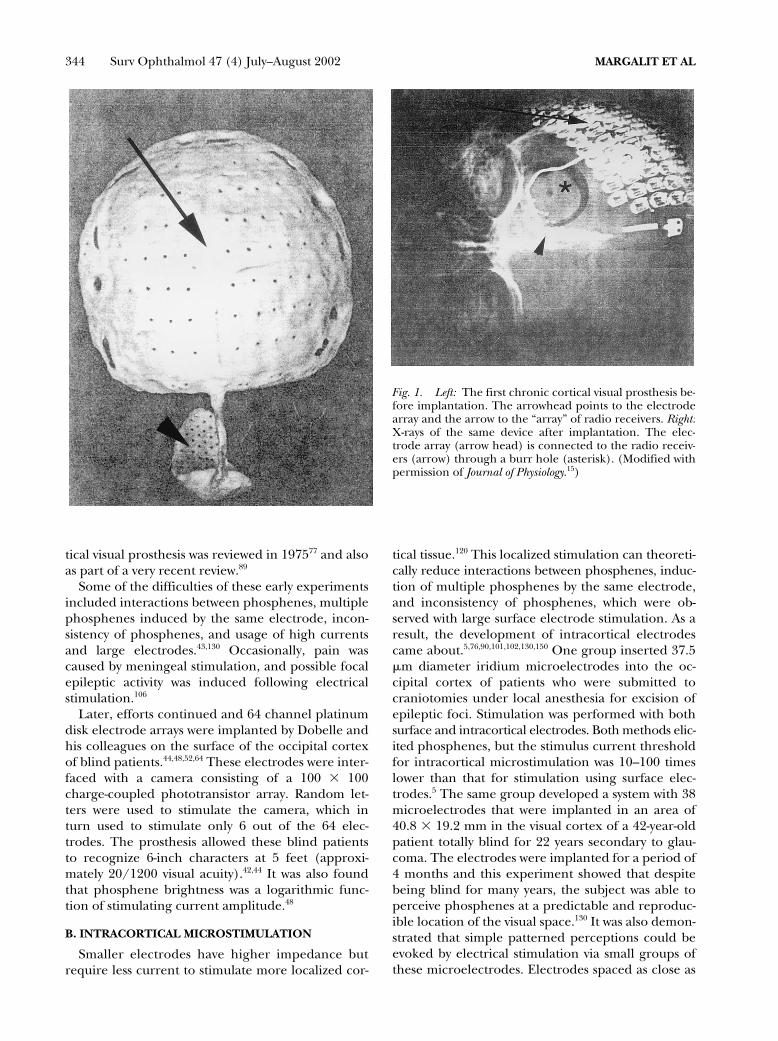
Brindley and Lewin performed key experimentsin this field by implanting devices consisting of 80electrodes on the visual cortex of blind patients (Fig.1). Wires through a burr hole connected each elec-trode to a radio receiver screwed to the outer bonysurface of the skull. An oscillator coil was placedabove a given receiver in order to activate the re-ceiver via radio frequency and stimulate the cortex.With this system, the patients were able to see phos-phenes at different positions of the visual field, dem-onstrating that many of the implanted electrodeswere functional. This experiment showed that achronically activated electrical stimulation multi-channel device was possible.15,17 The field of the cor-
344 Surv Ophthalmol 47 (4) July–August 2002 MARGALIT ET AL
tical visual prosthesis was reviewed in 197577 and alsoas part of a very recent review.89
Some of the difficulties of these early experimentsincluded interactions between phosphenes, multiplephosphenes induced by the same electrode, incon-sistency of phosphenes, and usage of high currentsand large electrodes.43,130 Occasionally, pain wascaused by meningeal stimulation, and possible focalepileptic activity was induced following electricalstimulation.106
Later, efforts continued and 64 channel platinumdisk electrode arrays were implanted by Dobelle andhis colleagues on the surface of the occipital cortexof blind patients.44,48,52,64 These electrodes were inter-faced with a camera consisting of a 100 � 100charge-coupled phototransistor array. Random let-ters were used to stimulate the camera, which inturn used to stimulate only 6 out of the 64 elec-trodes. The prosthesis allowed these blind patientsto recognize 6-inch characters at 5 feet (approxi-mately 20/1200 visual acuity).42,44 It was also foundthat phosphene brightness was a logarithmic func-tion of stimulating current amplitude.48
B. INTRACORTICAL MICROSTIMULATION
Smaller electrodes have higher impedance butrequire less current to stimulate more localized cor-
tical tissue.120 This localized stimulation can theoreti-cally reduce interactions between phosphenes, induc-tion of multiple phosphenes by the same electrode,and inconsistency of phosphenes, which were ob-served with large surface electrode stimulation. As aresult, the development of intracortical electrodescame about.5,76,90,101,102,130,150 One group inserted 37.5�m diameter iridium microelectrodes into the oc-cipital cortex of patients who were submitted tocraniotomies under local anesthesia for excision ofepileptic foci. Stimulation was performed with bothsurface and intracortical electrodes. Both methods elic-ited phosphenes, but the stimulus current thresholdfor intracortical microstimulation was 10–100 timeslower than that for stimulation using surface elec-trodes.5 The same group developed a system with 38microelectrodes that were implanted in an area of40.8 � 19.2 mm in the visual cortex of a 42-year-oldpatient totally blind for 22 years secondary to glau-coma. The electrodes were implanted for a period of4 months and this experiment showed that despitebeing blind for many years, the subject was able toperceive phosphenes at a predictable and reproduc-ible location of the visual space.130 It was also demon-strated that simple patterned perceptions could beevoked by electrical stimulation via small groups ofthese microelectrodes. Electrodes spaced as close as
Fig. 1. Left: The first chronic cortical visual prosthesis be-fore implantation. The arrowhead points to the electrodearray and the arrow to the “array” of radio receivers. Right:X-rays of the same device after implantation. The elec-trode array (arrow head) is connected to the radio receiv-ers (arrow) through a burr hole (asterisk). (Modified withpermission of Journal of Physiology.15)

RETINAL PROSTHESIS FOR THE BLIND 345
500 �m apart generated separate phosphenes, andat levels near threshold, the phosphenes usually hadcolors.5
Undoubtedly, the lower current threshold of theintracortical microstimulation, the predictableforms of generated phosphenes, the absence offlicker phenomena, reduction of phosphene interac-tions, the opportunity to increase the number ofelectrodes, and the reduced power requirement andcurrent per microelectrode are the main advantagesof the intracortical microstimulation approach oversurface cortical stimulation.5,130 Because of these ad-vantages all major efforts investigating the develop-ment of a visual cortical prosthesis have abandonedthe use of surface electrodes and are developing in-tracortical microelectrodes.
One of the groups has focused on the use ofdoped silicon penetrating electrode array for a corti-cal implant.102 The tips of the 1.5/1.0-mm long elec-trodes are covered with platinum. The array typicallylooks like a nail bed and consists of 100 penetratingelectrodes. The diameter of each electrode at itsbase is 80–100 �m and 2–3 �m at the tip. Tissue re-action to chronic implantation of this electrode ar-ray varied from no reaction at all or a thin capsulearound each electrode track, to gliosis, buildup of fi-brotic tissue between the array and the meninges, ar-ray displacement, and bleeding.102 Thin capsulesaround electrode tracks and tissue accumulation onpulsed CNS electrodes were also reported by oth-ers.2,94,156 Nevertheless, tissue encapsulation does notalways preclude effective stimulation.56,156
The preferable fixation site of the intracortical mi-crostimulation arrays is probably the cortex itselfand not the skull because of the constant movementof the brain in relation to the skull. The cortical ar-rays are currently inserted either by manual inser-tion of individual or groups of 2–3 electrodes nor-mal to the cortical surface to a depth of 2 mm130 orby a pneumatic system that inserts 100-electrode ar-rays into the cortex in about 200 msec.125
Another electrode technology for cortical stimula-tion uses silicon micromachining to fabricate multi-channel arrays for neural prostheses applications.Microfabricated silicon electrodes were initially con-ceived in the early 1970s.162 In subsequent years, thedimensions of these electrodes have been decreasedutilizing the concurrent advances in the microelec-tronics industry. Today, micromachined silicon elec-trodes with conducting lines of 2 �m or less are stan-dard.9,66,81,149 These fabrication processes have beenadvanced by the microelectronics industry andtherefore allow the integration of microelectronicsand the electrode array into a monolithic device.The primary reason for the inclusion of on-chipelectronics in such a device is to minimize the num-
ber of external leads required between the electrodesites and the outside world. Recording/stimulatingsites are located along the silicone probe substrate.These probes are capable of extracellular recording/stimulating of many cells in neural tissue simulta-neously on a spatially distributed basis.3,100,144,163
Chronic implantation and in vitro testing have demon-strated the ability of silicon devices to maintain electri-cal characteristics during long-term implantation.156
The biocompatibility of various chronic intracorti-cal stimulating arrays was examined. Preliminary ex-periments of chronic implantation of stimulating de-vices over the cortex revealed a fibrous membranecovering the surface of every implant that was exam-ined 6 weeks or more after insertion. These mem-branes had little effect on threshold for stimula-tion.15 There was only one report on the need toremove a chronic device from the cortical surface ofa patient because of a blood-borne infection.42
There are advantages and disadvantages that areassociated with the cortical stimulation approach ingeneral. The skull will protect both the electronicsand the electrode array and a visual cortical prosthe-sis will bypass all diseased neurons distal to the pri-mary visual cortex. By doing so, it has the potentialto restore vision to the largest number of blind pa-tients. However, spatial organization is more com-plex at the cortical level, and two adjacent corticalloci do not necessarily map out to two adjacent areasin space, so that patterned electrical stimulation maynot produce patterned perception. In addition, ev-ery small area of the cortex, even at the level of theprimary visual cortex, is highly specialized for color,motion, eye preference, and other parameters of vi-sual stimuli. Thus, it is unlikely to get simple percep-tions even when stimulating few hundreds of neu-rons in the case of intracortical microstimulation.Moreover, the convoluted cortical surface makes itdifficult for implantation, and surgical complica-tions can have devastating results (including death)on generally healthy subjects.
III. Retinal ProsthesesDuring the early seventies it became clear that
blind humans can also perceive electrically elicitedphosphenes in response to ocular stimulation, with acontact lens as a stimulating electrode.107–109 Whenobtainable, these electrically elicited responses indi-cated the presence of at least some functioning in-ner retinal cells. Because a number of blinding reti-nal diseases are due predominantly to outer retinal(in particular photoreceptor) degeneration,72,127,142
the idea of stimulating the remaining inner retinalcells came about. Early experiments showed that in-ner retinal layers can be electrically stimulated andelicit an electrical-evoked response (EER).78,79,147
346 Surv Ophthalmol 47 (4) July–August 2002 MARGALIT ET AL
Two of the more common outer retinal degenera-tive diseases are RP and AMD. The incidence of RPis 1/3,500 live births and there are approximately1.5 million people affected worldwide. It is the lead-ing cause of inherited blindness.24 Age-related macu-lar degeneration is the main cause of visual lossamong adults older than 65 in western countries.Annually, there are approximately 700,000 new pa-tients in the United States who lose vision due to thisillness and 10% of these who have the disease be-come legally blind each year.36
Postmortem morphometric analysis of the retinaof RP patients revealed that many more inner nu-clear layer cells (bipolar cells and others [78.4%]) areretained compared to outer nuclear layer (photore-ceptors [4.9%]) and ganglion cell layer (29.7%).72,
127,142 Similar results were obtained from AMD pa-tients (Kim et al: Morphometric analysis of the mac-ula in eyes with disciform age-related macular degen-eration. Under submission). Given that there islimited transynaptic neuronal degeneration, it is fea-sible to stimulate the remaining retinal neurons.
The exact retinal target cell for electrical stimula-tion is not trivial to identify because many of thestudies designed to explore this target cell were basedon extracellular recording of neuronal action poten-tials. However, it should be noted that in the retina,there are neurons (photoreceptor, bipolar, and hor-izontal cells) that when excited do not generate ac-tion potentials but only graded potentials.45 In theseneurons, electrical stimulation can evoke a gradedpotential that can be very difficult to document withextracellular recordings.
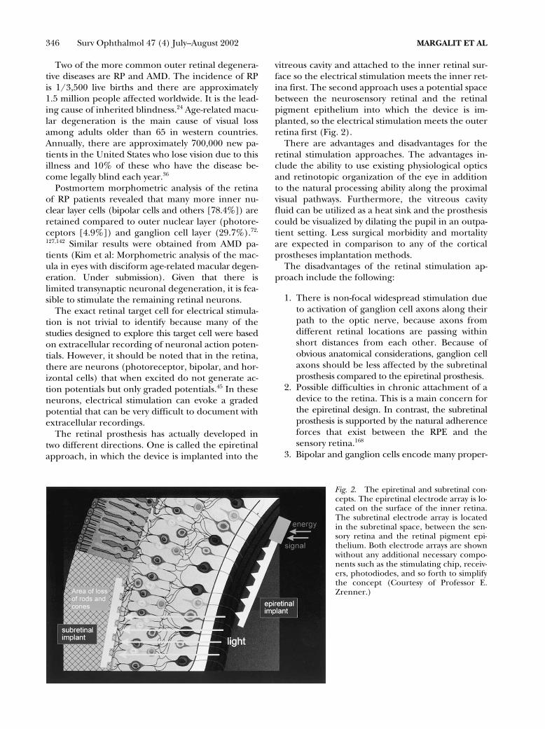
The retinal prosthesis has actually developed intwo different directions. One is called the epiretinalapproach, in which the device is implanted into the
vitreous cavity and attached to the inner retinal sur-face so the electrical stimulation meets the inner ret-ina first. The second approach uses a potential spacebetween the neurosensory retinal and the retinalpigment epithelium into which the device is im-planted, so the electrical stimulation meets the outerretina first (Fig. 2).
There are advantages and disadvantages for theretinal stimulation approaches. The advantages in-clude the ability to use existing physiological opticsand retinotopic organization of the eye in additionto the natural processing ability along the proximalvisual pathways. Furthermore, the vitreous cavityfluid can be utilized as a heat sink and the prosthesiscould be visualized by dilating the pupil in an outpa-tient setting. Less surgical morbidity and mortalityare expected in comparison to any of the corticalprostheses implantation methods.
The disadvantages of the retinal stimulation ap-proach include the following:
1. There is non-focal widespread stimulation dueto activation of ganglion cell axons along theirpath to the optic nerve, because axons fromdifferent retinal locations are passing withinshort distances from each other. Because ofobvious anatomical considerations, ganglion cellaxons should be less affected by the subretinalprosthesis compared to the epiretinal prosthesis.
2. Possible difficulties in chronic attachment of adevice to the retina. This is a main concern forthe epiretinal design. In contrast, the subretinalprosthesis is supported by the natural adherenceforces that exist between the RPE and thesensory retina.168
3. Bipolar and ganglion cells encode many proper-
Fig. 2. The epiretinal and subretinal con-cepts. The epiretinal electrode array is lo-cated on the surface of the inner retina.The subretinal electrode array is locatedin the subretinal space, between the sen-sory retina and the retinal pigment epi-thelium. Both electrode arrays are shownwithout any additional necessary compo-nents such as the stimulating chip, receiv-ers, photodiodes, and so forth to simplifythe concept (Courtesy of Professor E.Zrenner.)

RETINAL PROSTHESIS FOR THE BLIND 347
ties of the visible light (color, intensity, etc.) andthe question is which property will be encodedduring electrical stimulation if many bipolar andganglion cells are activated simultaneously.
4. This approach is limited to outer retinalpathologies.
A. EPIRETINAL PROSTHESES
Progress in the field of neural prostheses has con-verged with advances in retinal surgery to enable thedevelopment of an implantable retinal prosthesis.Currently, several groups have been developingepiretinal prostheses.38,47,69,70,164
Recently, intraocular acute (6–8 hours) epiretinalstimulation studies to examine the effects of electricstimulation were performed in primates.51 Function-ality of the prosthesis was confirmed by cortical EERrecording.
Similarly, blind RP and AMD patients were exam-ined acutely (�1 hour) to see if retinal electricalstimulation can evoke visual sensations.71 Prior tothe surgical procedure, patients had to pass ascreening test, which grossly tested the inner retinalfunction. They had to perceive light in response toelectrical stimuli delivered by a contact lens. Thesurgery involved a three-port pars plana vitreoreti-nal procedure with subconjunctival anesthesiaplaced only over the sclerotomies in order to avoiddisruptions of the optic nerve function. Differenttypes of stimulating electrodes were handheld onthe retinal surface. The patients were then asked totell the surgeons about their visual perceptions. Fo-cal electrical stimulation elicited phosphenes in allpatients and 4 out of 5 patients were able to de-scribe spatial and temporal aspects of the stimuli.The resolution could be estimated as 4.5/200, acrude ambulatory vision.
Epiretinal electric stimulation was tested again innine other RP and AMD patients.70 Two patientswere tested with an electrode array consisting of 3 �3, 5 � 5 or 3 � 7 electrodes (Fig. 3). Seven othersubjects were tested with simple devices consistingof 3 platinum electrodes packaged as a surgical in-strument in a hand-piece. The study showed thatelectrical stimulation threshold was dependent onthe electrode’s location (i.e., the macular region re-quired lower threshold currents than the peripheralretina to elicit visual perceptions). Also, patientswith less advanced RP or AMD required lowerthresholds currents than those with more advanceddisease. These findings are important because lowerthresholds would allow for smaller electrodes andgreater resolution.
Perhaps the most important result of this studywas associated with form recognition. Patients wereable to identify crude forms such as letters or a box
shape during the short period of electrical stimula-tion testing. When the electrical stimulation ended,there was no persistence of the image. Other impor-tant psychophysical perceptions in this study in-cluded flicker fusion (at a repetition rate of 40–50Hz) and different color perceptions.70
As discussed earlier, epiretinal prostheses will beexposed to ocular rotational movements that canreach a speed of more than 400 degrees/second.4
Bioadhesives, retinal tacks, and magnets were someof the methods examined for epiretinal attachment.In one study, the retinal tacks and the electrode ar-ray remained firmly affixed to the retina for up to 1year of follow-up with no significant clinical or histo-logical side effects.85 Similar results were shown inrabbits.155 In another study, nine commercially avail-able compounds were examined for their suitabilityas intraocular adhesives in rabbits. One type of adhe-sive (SS-PEG hydrogel, Shearwater Polymers Inc.)proved to be strongly adherent and non-toxic to theretina.86
Another disadvantage of the epiretinal prosthesisis the relative distance from its target cells. Thethickness of the nerve fiber and ganglion cell layersis at least 20–200 and 20–40 �m, respectively. Sincethere is a 3-dB rise in threshold for every 250 �m indistance (up to 1 mm) from a stimulating electrode(400-�m diameter platinum electrode),54 more cur-rent will be theoretically necessary for electrical stim-ulation than if the electrodes were in close contactto their target cells. Some of the charge densitythreshold values (0.16–70 mC/cm2) for acute epiret-inal stimulation of patients blind from RP, were well
Fig. 3. Acute epiretinal electrical stimulation in a RP hu-man patient with 3 � 7 electrode array.

348 Surv Ophthalmol 47 (4) July–August 2002 MARGALIT ET AL
above the safe threshold for Pt electrodes chronicstimulation (see section In Vivo Characterization ofEpiretinal Excitation).71 These values are affected bythe fact that many times the stimulating electrodesin acute experiments were as far as 0.5 mm from theretinal surface. Nevertheless, these are diseased reti-nas that require increased charge for stimulation.71
In order to reduce the charge density and keep itwithin safe limits for long-term stimulation, oneshould use either larger electrodes and thus loseresolution, or get closer to the target cells, that is,penetrate into the retina.
The cell bodies (somas) of these ganglion cells aremapped over the retinal surface in locations that ap-proximate the projection of the visual world ontothe same surface. However, at any particular loca-tion on the retinal surface, axons from peripheralsites overlay the individual ganglion cell bodies. Ifthese superficial passing axons were preferentiallystimulated, groups of ganglion cells from large areasof the retina would be excited. One might expectthe visual perception of such a stimulus to appear asa wedge or arc because of the characteristic courseof the ganglion cell axons in the nerve fiber layer.On the other hand, if the ganglion cell bodies ordeeper retinal cells were stimulated, one would ex-pect the visual perceptions to be focal spots.71 WhenRP and AMD patients’ retinas were stimulated with50–200 �m diameter platinum disk electrodes, thepatients reported of spots of light and not wedges.70,71
This would implicate that the electrodes did notpreferentially stimulate the RGC axons.
Stimulating the bipolar cells will allow more of thenatural retinal processing to take place. Stimulatingthe ganglion cells, which are closer to the epiretinalelectrode array, may require less current but wouldrequire more image processing and complex stimu-lation patterns to account for the lost retinal pro-cessing. Recently, latency and strength-duration ex-periments that were conducted in isolated frogretinas suggested that higher currents stimulateRGC directly while lower currents activate other cells(photoreceptors, bipolar cells).54 Another findingwas that the target cells of shorter pulse duration(� 0.5 msec) were RGC cells/axons whereas adeeper cellular elements were the target for longerpulse duration (� 0.5 msec).54 This is consistent withthe finding that deeper retinal cells have unusuallylong chronaxies compared to RGC.54 Thus, there areseveral lines of evidence to suggest that epiretinalelectrical stimulation of the retina can result in well-defined retinotopic visual percepts, and that RGCsand RGC axons stimulation can be avoided by usinglong pulse duration in excess of 0.5 msec. More invitro and in vivo data should be collected to verifythese results in the future.
Different aspects of the safety of the epiretinal pros-thesis were examined in several experiments. Someexperiments used only sham devices with no electricalstimulation in order to examine mechanical biocom-patibility. In one such study, performed in 4 dogs, noretinal detachment occurred and only RPE changeswere noted near the retinal tacks, which were used forfixation of the epiretinal implant.85 In another study itwas reported that 9 out of 10 rabbits were implantedwith an epiretinal device without serious complica-tions. The implant was stable at its original fixationarea and no change in retinal architecture under-neath the implant was found by light microscopy. Inthree cases, mild cataract formation was observed,and in one case, a total retinal detachment was foundafter 6 months of follow up.155
Epiretinal implantation has the advantage ofkeeping most of the electronics off the retinal sur-face (Fig. 4), in the vitreous cavity, a naturally exist-ing and fluid filled space, which greatly helps in dis-sipating the heat generated by the electronics.105
Previously, the epiretinal intraocular prosthetic chipincluding a photosensor, processor and a stimulus-driving chip was developed.83 However, it becameapparent that an improvement could be achieved inhaving photosensing47 or video capture performedextraocularly, allowing for enhanced video process-ing, more custom control over the video signal, andless hardware to be implanted into the eye.84 Thetwo units can be connected either by infrared la-ser,117 or by inductive link telemetry (Fig. 4),63,84,148
allowing the intraocular unit to derive both powerand data signals from the extraocular unit. The ex-traocular unit includes a video camera and a videoprocessing board, a telemetry encoder chip, a radiofrequency amplifier, and primary coil (or lasersource). The intraocular unit consists of a secondarycoil (or a photovoltaic receiver), a rectifier and regu-lator, a retinal stimulator with a telemetry protocoldecoder, a stimulus signal generator and an elec-trode array.
1. In Vitro Characterization of Epiretinal Excitation
Several in vitro experiments with isolated retinapreparations have shown that neuronal activity canbe evoked by electrical stimulation. Early experi-ments showed that secondary slow-wave retinal po-tentials have been induced by trans-retinal electricalstimulation of an amphibian eye cup preparation.78,79
Such experiments allow us to delineate electrodeshapes and pulse parameters in controlled settings.In vitro experiments to define threshold currents forretinal electrical stimulation were performed in dif-ferent preparations. Threshold parameters duringvarious in vitro electrical stimulation experimentsare shown in Table 3.

RETINAL PROSTHESIS FOR THE BLIND 349
One study of normal retinal stimulation was per-formed in bullfrog eyecups and reported a chargedensity threshold of 2.98 �C/cm2.69 Another studywas performed with rabbit isolated retinas. Chargedensity threshold values were between 30 �C/cm2
and 917 �C/cm2.59 These results were similar tofindings in isolated human retina, concluding thatrabbits are a good model to study retinal electricalstimulation.59
2. In Vivo Characterization of Epiretinal Excitation
Because many of the experiments to develop asafe and effective implantation in humans have beenand will be performed in animals, indirect methodsof recording the function of the central visual systemhave been developed. Threshold parameters duringvarious in vivo electrical stimulation experiments areshown in Table 2.
Several experiments using scalp and subdermalelectrodes positioned over the visual cortex wereperformed to demonstrate that EER can be re-corded after external electrical stimulation of theeye.38,54,107–109,138,147
Penetrating electrodes within the cortical tissuehave the potential to record single neuron activity inaddition to multi-unit activity recorded by epiduralelectrodes.90,137 Other invasive methods for record-ing visually evoked potentials or EERs were tested.An epiretinal microfilm electrode array was used tostimulate the retina in normal cats.65 The evoked po-tentials were recorded with epidural recording elec-trodes positioned over the visual cortex. The chargebalanced threshold value was 178 �C/cm2. Recently,subdural electrodes were compared to subdermalelectrodes in recording visual and electrical-evokedpotentials in dogs.87 Electrical stimuli of 1 msec 6
mA elicited an 87.3 �V amplitude response that wasrecorded with subdural electrodes vs. 1.1 �V thatwas recorded with subdermal electrodes (in thesame animal). In addition, the amplitude of the VEPrecorded with subdural electrodes was higher thanthe one recorded with sub-dermal electrodes (159.5vs. 9.9 �V, respectively).
B. SUBRETINAL PROSTHESES
Several groups have been developing subretinalprostheses.31,171 The subretinal space is obviously agood location to stimulate the bipolar cells becauseof its physical proximity to the inner nuclear layer(Fig. 5).
The artificial silicon retina (ASR) is a subretinalprosthetic device comprised of subunits measuring20 � 20 �m.31 Every subunit is a combination of a sil-icon microphotodiode and a stimulating electrode.The density of the subunits is 1100 subunits/mm2.These subunits are designed to convert the light en-ergy from images into electrical impulses to stimu-late the remaining functional cells of the retina inpatients with AMD and RP types of conditions. TheASR is powered solely by incident light and does notrequire the use of external wires or batteries. By con-verting light into electrochemical signals, the micro-scopic solar cells on the chip mimic the function ofthe photoreceptors to stimulate the remaining via-ble cells of the retina. These solar cells, in turn, acti-vate the adjacent electrode in the subunit and thuscreate an electrical current, which stimulate adja-cent retinal tissue. This translates into a relativelysimple intraocular operation and array activation.The surgical procedure can be performed extraocu-larly through the sclera (ab externo) or intraocularlythrough a retinotomy site after a standard vitrectomy
Fig. 4. A sketch of an epiretinal implant shown with ex-traocular primary coil (*) and an intraocular secondarycoil in the sulcus of the ciliary body (+). The receiver andthe stimulating chips are located in the mid-vitreous (**)and connected to the epiretinal electrode array (++).
Fig. 5. Fundus photograph of a cat taken approximately3 months after a subretinal implantation of a microphoto-diode array in a cat. (Reprinted with permission of MartinDunitz, Ltd.33)

350 Surv Ophthalmol 47 (4) July–August 2002 MARGALIT ET AL
procedure (ab interno). The ab externo procedureis performed by preparing a scleral flap 6 mm fromthe limbus. Intraocular pressure is reduced by para-centhesis. Then the choroid is incised and a custom-made implantation tool is used to insert the deviceinto the subretinal space.171 The subretinal approachtakes advantage of the adherence forces between thesensory retina and the retinal pigment epithelium tokeep the array in place. In some occasions though,the array can be displaced after implantation.104
Recently, phase I clinical trials (IDE) of subretinalvisual prosthesis implantation in three human sub-jects were announced. The retinal prosthesis, mea-suring 2 mm in diameter and 25 �m of thickness,contained 3,500 solar cells that generate power fromlight received by the eye.98 Later, the same group im-planted silicon chip artificial retinas into the eyes ofthree additional patients blinded by retinal diseases,continuing a first-of-its-kind safety, feasibility, and ef-ficacy study to restore visual function.32 The implan-tation takes about 1.5–2 hours to complete. The pa-tients were all discharged from the hospital 1 daylater and recovered at home. The subretinal posi-tioning of the retinal prosthesis has the advantage ofplacing the stimulating electrodes closer to the bipo-lar cells, which may also permit lower stimulusthresholds.30,31,60,104,145,171
Several biocompatibilty issues of the subretinal ap-proach have been studied. These include limitationof the implant power generation by size require-ments,104 and creation of a mechanical barrier be-tween the retina and the choroid, which providesnourishment to the outer layers of the retina.171
Modern-day photovoltaic or solar cells are rela-tively inefficient compared to the natural photore-ceptors of the eye. In order to activate neurons, solarcells need to provide electrical energy many ordersof magnitude higher than the amount of currentproduced under typical retinal illumination. Thistranslates, based on empirical and theoretical calcu-lations, into using a very bright image intensifier (20suns or 2000 W/m2) in order for the stimulator chipto generate the level of currents that have resultedin visual perceptions in the blind. This, however, canbe overcome by adding more energy in the near in-frared light spectrum of solar cells and minimizingthe electrode surface area. These concepts are inves-tigated and partially proven by subretinal prosthesisgroups and further improvements are anticipated inthis area (see section Power Supply).31,131,132
A mechanical barrier between the retina and thechoroid might be responsible to patches of fibrosisand RPE changes that were found after chronic sub-retinal implantation. The histology of the retinashowed declining inner nuclear and ganglion celllayer densities, but no inflammatory response.104
Another report showed that there was irregularglial proliferation above the electrode array.171
However, in another study, three rabbits were im-planted with an electrode array in the subretinalspace. No side effects were reported.30 Similarly,micropigs were sacrificed after an implantation pe-riod of 14 months.50 The outer retina degeneratedbut the inner retina remained intact with no Müllercell proliferation. To prevent a possible barrier ef-fect, one of the groups incorporated porous elec-trode array structures to facilitate nutritional ex-change between the retina and the underlyingchoroid.131
1. In Vitro Characterization of Subretinal Excitation
Several groups examined the threshold for subret-inal electrical stimulation. These studies were per-formed by stimulation from the photoreceptor sideof the retina. Human testing has shown that stimula-tion threshold vary greatly depending on the healthof the retina. Thus, it is important from the stand-point of developing a retinal prosthesis to compareelectrical stimulation experiments of normal to de-generated isolated retina.
The charge density threshold values of one ofthese studies were in the range of similar epiretinalin vitro experiments (178 �C/cm2).141 This study wasperformed on isolated normal chicken retina. Theresults also demonstrated that spatially organizedelectrical stimulation could produce spatially dis-cernible responses in retinal output. Another study,performed on isolated retinas from retinal degener-ate rats (RCS), reported of a threshold charge den-sity of 500 �C/cm2.140 These studies were done withthe “sandwich preparation,” that is, stimulating witha micro-electrode array from one side of the retinaand recording with a patch electrode placed on thecell bodies of the RGC from the other side of the ret-ina.50,141 Similar to epiretinal human experiments,we can see that a much higher charge density thresh-old is required to stimulate diseased retinas. Onepossible explanation for this phenomenon is thatphotoreceptors have the lowest thresholds and sincedegenerated retinas lack photoreceptors, muchhigher charge density values are required to activatethe remaining cells.
2. In Vivo Characterization of Subretinal Excitation
The ability to electrically stimulate the retina witha subretinal device and record central nervous re-sponses were demonstrated in several experiments.In one experiment, subretinal electrodes connectedto extraocular photodiodes were implanted in threerabbits and tested acutely.29 Aside from incidentlight stimuli, no external power source was used.Flash stimuli were provided with a Grass PS-22 pho-

RETINAL PROSTHESIS FOR THE BLIND 351
tostimulator. Cortical potentials were recorded fromsubdermal electrode placed at the occiput. Corticalresponses were recorded from all three rabbits andmaintained even when the stimulation polarity wasreversed (this is a well-known method to examine ifthe elicited response from electrical stimulation ofneuronal tissue is an electrophysiological responseor an artifact. If the response has the same polarityafter the stimulation polarity is reversed, then it isconsidered a real electrophysiological response. If,instead, the polarity of the response changes afterreversal of the stimulation polarity, it is consideredto be an electrical artifact). The magnitude of thecortical responses declined as the stimulating chargedensity was reduced from 1 � 107 to 2.8 � 109
C/cm2. These results demonstrated the general con-cept of converting light into electrical energy, stimu-lating the retina, and recording EER at the level ofthe visual cortex.
A similar study was performed with rabbits and mi-cropigs.50 In this experiment, no light source wasused but instead the subretinal implanted electrodeswere pulsed with 3V 400 �sec electrical stimuli. EERwas recorded in both species in response to electri-cal stimulation.
IV. Optic Nerve ProsthesesInvestigators have also stimulated the optic
nerve.133,134,153 The optic nerve is a compact compart-ment of ganglion cell axons running from the retinaand synapse on the lateral geniculate body. Thiscondensed cable can be reached surgically, and the-oretically has a good location for implanting a sur-face or penetrating stimulation electrode array.However, the high density of the axons (1.2 millionwithin a 2 mm-diameter cylindrical structure) couldmake it difficult to achieve focal stimulation and de-tailed perceptions. In addition, any surgical ap-proach to the optic nerve requires dissection of thedura and can have harmful side effects, includingCNS infection, disturbance of blood flow to the op-tic nerve, and so forth. Similar to the retinal prosthe-sis approach, optic nerve stimulation requires intactRGC and is limited to outer retinal pathologies.
Recently, one of the groups chronically implanteda self-sizing spiral cuff electrode21 with four electricalcontacts around the optic nerve of a 59 year-oldblind RP patient (Fig. 6). Electrical stimuli appliedto the optic nerve produced localized, often colored,phosphenes that were broadly distributed through-out the visual field and were still reliably reinduced118 days after surgery. Changing the pulse duration,pulse amplitude, or pulse repetition rate could varyphosphene brightness.153 After training, the patientcould recognize different shapes, line orientations,and even letters151
During this unique intracranial implantation ofoptic nerve stimulating electrodes in a human, noacute or chronic side effects were noted.153 No acutedamage was noted after electrical stimulation of thesciatic nerve of cats with similar cuff electrodes.152
Yet another approach called a “Hybrid Retinal Im-plant” proposes to develop a visual prosthesis, whichwould include both electronic and cellular compo-nents. The electronics will perform image recogni-tion and the neurons on the device will extend theiraxons to synapse with the lateral geniculate body,thus create the device–CNS interface, and restore vi-sion.165,166 The advantage of this approach is to beable to replace an eye with total or inner retinal de-generation. Disadvantages include difficulties in pre-cisely directing axons to the lateral geniculate body,developing the interface between the electronicsand neurons, and developing the matrix to enablesurvival of the cellular components while beinghoused in microelectronics. The Hybrid Retinal Im-plant is in the early stages of development and itssuccessful implementation will depend on advancesin retinal cell culture as well as microelectronics.
V. Sensory Substitution DevicesAs an alternative to direct stimulation of the visual
system neurons, several other approaches have at-tempted to convert visual information into vibro-tactile or auditory signals (i.e., sensory substitutiondevices12,115). The distinct advantage of these ap-proaches is that the device is wearable and not im-plantable. However, these devices have neverreached widespread acceptance because they do not
Fig. 6. A sketch of a right optic nerve device after implan-tation. The cuff electrode was implanted intracranially.The cable passes through the skull and courses below theskin and along the outer surface of the skull. It then passesdown the neck to exit the skin below the clavicle. (Re-printed with permission of Brain Research.153)

352 Surv Ophthalmol 47 (4) July–August 2002 MARGALIT ET AL
restore the sensation of vision, have low resolution,occupy another sensory modality, can evoke pain,and can have a prolonged learning period.
VI. SummaryThe three levels of hierarchy in the sensory systems
(i.e., receptor organ, sensory pathways, and percep-tion) suggest a similar architecture for artificial andprosthetic sensory systems. Accordingly, artificial sys-tems should include a transducer corresponding tothe receptor organ, an encoder corresponding to thesensory processing system, and finally an interpretercorresponding to perceptual functions. In otherwords, the visual environment will be captured andprocessed by a photosensing device such as a digitalcamera or photovoltaic units. This pixelized informa-tion is then transformed to electrical energy by micro-photodiode array or conducted to a stimulating com-ponent that in turn activates an electrode array with asimilar pixelized pattern.
Adjusting pulse parameters and minimizing inter-actions between pulses on adjacent electrodes canimprove the neural response. The electrical stimula-tor device output should be characterized by theflexibility of several parameters such as amplitude,pulse width, repetition rate, pulse shape, and so on.
Attempts at implanting electronic devices at vari-ous parts along the visual pathways were discussed.Both major achievements and obstacles remainingwere summarized. Given that intact neurons alongthe visual pathways can be found in almost all blindpatients, only our lack of experience and capabilitiesin physiology, biocompatibility and device–tissue in-terfacing is preventing us from stimulating them in asafe and effective manner. We believe that as ourknowledge increases about how to stimulate neuronswith microelectronics and as microelectronics andmaterial sciences continue to evolve, we should oneday be able to restore vision to the blind. Given theadvances that have been made in this field we canonly hope that the day such devices are widely usedis in the near future and not decades away.
Method of Literature SearchA literature search of the PubMed data was per-
formed (1966–present). The following key wordswere used: artificial vision, blindness, cortical prosthesis,electrical stimulation electronic implants, macular degener-ation, optic nerve, optic nerve prosthesis, retina, retinalprosthesis, retinitis pigmentosa, visual cortex and visualprosthesis. In addtion, some abstracts from relevantrecent conferences and annual meetings were re-viewed. The search was not limited to English lan-guage, but only English abstracts were used. We in-cluded references that we considered to have madea major contribution to research and development
in this field. Minor references were included if theysupported a certain point made by other referencesor contributed new ideas, methods, or very recentadvances.
References1. Acland GM, Aguirre GD, Ray J, et al: Gene therapy restores
vision in a canine model of childhood blindness. Nat Genet28:92–95, 2001
2. Agnew WF, Yuen TGH, McCreery DB, Bullara L: Histo-pathologic evaluation of prolonged intracortical electricalstimulation. Experimental Neurology 92:162–85, 1986
3. Anderson DJ, Najafi K, Tanghe SJ, et al: Batch-fabricatedthin-film electrodes for stimulation of the central auditorysystem. IEEE Trans Biomed Eng 36:693–704, 1989
4. App E, Debus G: Saccadic velocity and activation: develop-ment of a diagnostic tool for assessing energy regulation.Ergonomics 41:689–97, 1998
5. Bak M, Girvin JP, Hambrecht FT, et al: Visual sensationsproduced by intracortical microstimulation of the humanoccipital cortex. Med Biol Eng Comput 28:257–9, 1990
6. Bard AJ, Faulkner LR: Electrochemical Methods: Funda-mentals and Applications. New York, John Wiley & Sons,1980, pp 213–48
7. Beebe X, Rose TL: Charge injection limits of activated irid-ium oxide electrodes with 0.2 ms pulses in bicarbonatebuffered saline. IEEE Trans Biomed Eng 35:494–5, 1988
8. BeMent SL, Ranck JB Jr: A model for electrical stimulationof central myelinated fibers with monopolar electrodes.Exp Neurol 24:171–186, 1969
9. BeMent SL, Wise KD, Anderson DJ, et al: Solid-state elec-trodes for multi-channel multiplexed intracortical neu-ronal recording. IEEE Trans Biomed Eng 33:230–41, 1986
10. Berson EL, Rosner B, Sandberg MA, et al: A randomizedtrial of vitamin A and vitamin E supplementation for retini-tis pigmentosa. Arch Ophthalmol 111:761–72, 1993
11. Bostock H: The strength-duration relationship for excita-tion of myelinated nerve: computed dependence on mem-brane parameters. J Physiol 341:59–74, 1983
12. Brabyn JA: New developments in mobility and orientationaids for the blind. IEEE Trans Biomed Eng 29:285–9, 1982
13. Bressler NM: Photodynamic therapy of subfoveal choroidalneovascularization in age-related macular degenerationwith verteporfin: two-year results of 2 randomized clinicaltrials—TAP report 2. Arch Ophthalmol 119:198–207, 2001
14. Brindley GS: The number of information channels neededfor efficient reading. J Physiol 177:44, 1965
15. Brindley GS, Lewin WS: The sensations produced by electricalstimulation of the visual cortex. J Physiol 196:479–93, 1968
16. Brindley GS, Lewin WS: The visual sensations produced byelectrical stimulation of the medial occipital cortex. J Phys-iol 194:54–5, 1968
17. Brindley G, Rushton D: Implanted stimulators of the visualcortex as visual prosthetic devices. Trans Am Acad Oph-thalmol Otolaryngol 78:741–5, 1974
18. Brown WJ, Babb TL, Soper HV, et al: Tissue reactions tolong-term electrical stimulation of the cerebellum in mon-keys. J Neurosurg 47:366–79, 1977
19. Brummer SB, Turner MJ: Electrical stimulation of the ner-vous system: the principle of safe charge injection with no-ble metal electrodes. Bioelectrochem Bioenerg 2:13–25,1975
20. Brummer SB, Turner MJ: Electrochemical considerationsfor safe electrical stimulation of the nervous system withplatinum electrodes. IEEE Trans Biomed Eng 24:59–63,1977
21. Buckett JR, Peckham PH, Thrope GB, Braswell SD, KeithMW: A flexible, portable system for neuromuscular stimula-tion in the paralyzed upper extremity. IEEE Trans BiomedEng 35:897–904, 1988
22. Buffet J: Technological progress in pacemaker design: her-metic sealing. Med Prog Technol 3:133–42, 1975
RETINAL PROSTHESIS FOR THE BLIND 353
23. Bullara LA, McCreery DB, Yuen TG, Agnew WF: A micro-electrode for delivery of defined charge densities. J Neuro-sci Methods 9:15–21, 1983
24. Bunker CH, Berson EL, Bromley WC, Hayes RP, RoderickTH: Prevalence of retinitis pigmentosa in Maine. Am JOphthalmol 97:357–65, 1984
25. Button J, Putnam T: Visual responses to cortical stimula-tion in the blind. J Iowa St Med Soc 52:17–21, 1962
26. Cha K, Horch K, Normann RA: Simulation of a phosphene-based visual field: visual acuity in a pixelized vision system.Ann Biomed Eng 20:439–49, 1992
27. Cha K, Horch KW, Normann RA: Mobility performancewith a pixelized vision system. Vision Res 32:1367–72, 1992
28. Cha K, Horch KW, Normann RA, Boman DK: Readingspeed with a pixelized vision system. J Opt Soc Am 9:673–7,1992
29. Cheng Y, Lin L, Najafi K: Fabrication and hermeticity test-ing of a glass-silicon package formed using localized alumi-num/silicon-to-glass bonding. IEEE 13th Ann InternatConf Microelectromechanical Sys 757–62, 2000
30. Chow AY, Chow VY: Subretinal electrical stimulation of therabbit retina. Neurosci Lett 225:13–6, 1997
31. Chow AY, Peachey NS: The subretinal microphotodiode ar-ray retinal prosthesis. Ophthalmic Res 30:195–8, 1998
32. Chow AY: Silicon chips implanted into the eyes of three pa-tients to treat blindness. Available at http://optobion-ics.com/010730pressrelease.htm 2001.
33. Chow AY, Pardue MT, Peyman GA, Peachey NS: Develop-ment and application of subretinal semiconductor micro-photodiode array, in Peyman GA, Meffert SA, Conway MD,Chou F (eds): Vitreoretinal Surgical Techniques. London,Martin Dunitz Ltd, 2001, pp 576
34. Clark GM: Electrical stimulation of the auditory nerve: thecoding of frequency, the perception of pitch and the devel-opment of cochlear implant speech processing strategiesfor profoundly. Clin Exp Pharmacol Physiol 23:766–76,1996
35. Clark GM, McAnally KI, Black RC, Shepherd RK: Electricalstimulation of residual hearing in the implanted cochlea.Ann Otol Rhinol Laryngol 166(Suppl):111–3, 1995
36. Curcio CA, Medeiros NE, Millican CL: Photoreceptor lossin age-related macular degeneration. Invest OphthalmolVis Sci 37:1236–49, 1996
37. Dagnelie G, Thompson J, Barnett D, Zhang W: Simulatedprosthetic vision: Perceptual and performance measures,Vision Science and its Application, OSA Technical Digest.Washington DC, Optical Society of America, in press
38. Dawson WW, Radtke ND: The electrical stimulation of theretina by indwelling electrodes. Invest Ophthalmol Vis Sci16:249–52, 1977
39. del Cerro M, Gash DM, Rao GN, Notter MF, Wiegand SJ,Sathi S, del Cerro C: Retinal transplants into the anteriorchamber of the rat eye. Neuroscience 21:707–23, 1987
40. Dineen P, Drusin L: Epidemics of postoperative wound in-fections associated with hair carriers. Lancet 2:1157–9, 1973
41. Djourno A, Eyries C: Prothese auditive par excitation elec-trique a distance du nerf sensorial a l’aide d’un bobinageinclus a demeure. Presse Med 35:14–7, 1957
42. Dobelle WH: Artificial vision for the blind by connecting atelevision camera to the visual cortex. ASAIO J 46:3–9, 2000
43. Dobelle WH, Mladejovsky MG: Phosphenes produced byelectrical stimulation of human occipital cortex, and theirapplication to the development of a prosthesis for theblind. J Physiol 243:553–76, 1974
44. Dobelle WH, Mladejovsky MG, Evans JR, et al: “Braille”reading by a blind volunteer by visual cortex stimulation.Nature 259:111–2, 1976
45. Dowling JE: The retina: an approachable part of the brain.London, Belknap Press, 1987, pp 81–123
46. Dougherty SH, Simmons RL: Infections in bionic man: thepathobiology of infections in prosthetic devices—Part II.Curr Probl Surg 19:265–319, 1982
47. Eckmiller R: Learning retina implants with epiretinal con-tacts. Ophthalmic Res 29:281–9, 1997
48. Evans JR, Gordon J, Abramov I, et al: Brightness of phos-phenes elicited by electrical stimulation of human visualcortex. Sens Processes 3:82–94, 1979
49. Foerster O: Beitrage zur pathophysiologie der sehbahnund der spehsphare. J Psychol Neurol 39:435–63, 1929
50. Gekeler F, Schwahn H, Stett A, et al: Subretinal micropho-todiodes to replace photosensor function, a review of cur-rent state, in Doly M, Droy-Lefaix M, Christen Y (eds): Vi-sion, Sensations et Environments. Paris, Irvinn, 2001, pp77–95
51. Gerding H, Hornig R, Eckmiller R, et al: Implantation, me-chanical fixation, and functional testing of epiretinal multi-microcontact arrays (MMA) in primates [abstract]. InvestOphthlamol Vis Sci 42(Suppl):S814, 2001
52. Girvin JP, Evans JR, Dobelle WH, et al: Electrical stimula-tion of human visual cortex: the effect of stimulus parame-ters on phosphene threshold. Sens Processes 3:66–81, 1979
53. Gorman PH, Mortimer JT: The effect of stimulus parame-ters on the recruitment characteristics of direct nerve stim-ulation. IEEE Trans Biomed Eng 30:407–14, 1983
54. Greenberg RJ: Analysis of electrical stimulation of the ver-tebrate retina- work towards a retinal prosthesis. PhD Dis-sertation, The Johns Hopkins University Baltimore, MD,1998
55. Greenberg RJ, Velte TJ, Humayun MS, et al: A computa-tional model of electrical stimulation of the retinal gan-glion cell. IEEE Trans Biomed Eng 46:505–14, 1999
56. Grill WM, Mortimer JT: Electrical properties of implant en-capsulation tissue. Ann Biomed Eng 22:23–33, 1994
57. Grill WM, Mortimer JT: Stability of the input-output prop-erties of chronically implanted multiple contact nerve cuffstimulating electrodes. IEEE Trans Rehabil Eng 6:364–73,1998
58. Grill WM, Mortimer JT: The effect of stimulus pulse dura-tion on selectivity of neural stimulation. IEEE TransBiomed Eng 43:161–6, 1996
59. Grumet AE, Wyatt JL, Rizzo JF: Multi-electrode stimulationand recording in the isolated retina. J Neurosci Methods101:31–42, 2000
60. Guenther E, Troger B, Schlosshauer B, Zrenner E: Long-term survival of retinal cell cultures on retinal implant ma-terials. Vision Res 39:3988–94, 1999
61. Harpster T, Hauvespre S, Dokmecy M, et al: A passive hu-midity monitoring system for in-situ remote wireless testingof micropackages. IEEE 13th Ann International Conf Mi-croelectromechanical Sys , 335–40, 2000
62. Harris J: Survey of breast implants from the point of view ofcarcinogenesis. Plast Reconstr Surg, 28:81, 1961
63. Heetderks WJ: RF powering of millimeter and submillime-ter sized neural prosthetic implants. IEEE Trans BiomedEng 35:323–6, 1988
64. Henderson DC, Evans JR, Dobelle WH: The relationshipbetween stimulus parameters and phosphene threshold/brightness, during stimulation of human visual cortex.Trans Am Soc Artificial Intern Organs 25:367–71, 1979
65. Hesse L, Schanze T, Wilms M, Eger M: Implantation of ret-ina stimulation electrodes and recording of electrical stim-ulation responses in the visual cortex of the cat. GraefesArch Clin Exp Ophthalmol 238:840–5, 2000
66. Hetke JF, Lund JL, Najafi K, Wise KD, Anderson DJ: Siliconribbon cables for chronically implantable microelectrodearrays. IEEE Trans Biomed Eng 41:314–21, 1994
67. Hodgkin A, Huxley A: A quantitative description of mem-brane current and its application to conduction and excita-tion in nerve. J Physiol 117:500–44, 1952
68. Hodgkin A, Huxley A: Currents carried by sodium and po-tassium ions through the membrane of the giant axon ofloligo. J Physiol 116:472–9, 1952
69. Humayun M, Propst R, de Juan E Jr, et al: Bipolar surfaceelectrical stimulation of the vertebrate retina. Arch Oph-thalmol 112:110–6, 1994
70. Humayun MS, de Juan E Jr, Weiland JD, et al: Pattern elec-trical stimulation of the human retina. Vision Res 39:2569–76, 1999

354 Surv Ophthalmol 47 (4) July–August 2002 MARGALIT ET AL
71. Humayun MS, de Juan E Jr, Dagnelie G, et al: Visual per-ception elicited by electrical stimulation of retina in blindhumans. Arch Ophthalmol 114:40–6, 1996
72. Humayun MS, Prince M, de Juan E Jr, et al: Morphometricanalysis of the extramacular retina from postmortem eyeswith retinitis pigmentosa. Invest Ophthalmol Vis Sci 40:143–8, 1999
73. Janders M, Egert U, Stelze M, Nisch W: Novel thin-film tita-nium nitride micro-electrodes with excellent charge trans-fer capability for cell stimulation and sensing applications.IEEE 19th International Conf EMBS, 1191–3, 1996
74. Jansen B, Schumacher-Perdreau F, Peters G, Pulverer G: Evi-dence for degradation of synthetic polyurethanes by Staphy-lococcus epidermidis. Zentralbl Bakteriol 276:36–45, 1991
75. Jones KE, Campbell PK, Normann RA: A glass/silicon com-posite intracortical electrode array. Ann Biomed Eng 20:423–37, 1992
76. Jones KE, Normann RA: An advanced demultiplexing sys-tem for physiological stimulation. IEEE Trans Biomed Eng44:1210–20, 1997
77. Karny H: Clinical and physiological aspects of the corticalvisual prosthesis. Surv Ophthalmol 20:47–58, 1975
78. Knighton RW: An electrically evoked slow potential of thefrog’s retina. I. Properties of response. J Neurophysiol 38:185–97, 1975
79. Knighton RW: An electrically evoked slow potential of thefrog’s retina. II. Identification with PII component of elec-troretinogram. J Neurophysiol 38:198–209, 1975
80. Ko WH, Liang SP, Fung CD: Design of radio-frequencypowered coils for implant instruments. Med Biol Eng Com-put 15:634–40, 1977
81. Kovacs GT, Storment CW, Rosen JM: Regeneration micro-electrode array for peripheral nerve recording and stimula-tion. IEEE Trans Biomed Eng 39:893–902, 1992
82. Lilly JC: Injury and excitation by electric currents: The bal-anced pulse-pair waveform, in Sheer DE (ed): ElectricalStimulation of the Brain. Austin, University of Texas Press,1961, pp 60–4
83. Liu W, McGucken E, Vitchiccom K, et al: Dual unit visualintraocular prosthesis. 19th IEEE Conf Engineering MedBiol 2303-6, 1997
84. Liu W, Vichienchom K, Clements M, et al: A neuro-stimu-lus chip with telemetry unit for retinal prosthesis device.IEEE Solid-State Circuits 35:1487–97, 2000
85. Majji AB, Humayun MS, Weiland JD, et al: Long-term histo-logical and electrophysiological results of an inactiveepiretinal electrode array implantation in dogs. InvestOphthalmol Vis Sci 40:2073–81, 1999
86. Margalit E, Fujii G, Lai J, et al: Bioadhesives for intraocularuse. Retina 20:469–77, 2000
87. Margalit E, Weiland J, Clatterbuck R, et al: Light and elec-trically evoked response (VER, EER) recorded from sub-dural epileptic electrodes implanted above the visual cor-tex in normal dogs [abstract]. Invest Ophthalmol Vis Sci42(Suppl):S814, 2001
88. Marshall SV, Skitek GG: Electromagnetic Concepts and Ap-plications. New Jersey, Prentice-Hall, 1987 ed 2, pp 58–72
89. Maynard EM: Visual prostheses. Annu Rev Biomed Eng 3:145–68, 2001
90. Maynard EM, Nordhausen CT, Normann RA: The Utah in-tracortical electrode array: a recording structure for poten-tial brain-computer interfaces. Electroencephal Clin Neu-rophysiol 102:228–39, 1997
91. McCreery DB, Agnew WF, Yuen TG, Bullara LA: Compari-son of neural damage induced by electrical stimulationwith faradaic and capacitor electrodes. Ann Biomed Eng16:463–81, 1988
92. McCreery DB, Agnew WF, Yuen TGH, Bullara L: Chargedensity and charge per phase as cofactors in neural injuryinduced by electrical stimulation. IEEE Trans Biomed Eng37:996–1001, 1990
93. McCreery DB, Bullara L, Agnew WF: Neuronal activityevoked by chronically implanted intracortical microelec-trodes. Exp Neurol 92:147–61, 1986
94. McCreery DB, Yuen TG, Agnew WF, Bullara LA: A charac-terization of the effects on neuronal excitability due to pro-longed microstimulation with chronically implanted micro-electrodes. IEEE Trans Biomed Eng 44:931–9, 1997
95. McCreery D, Agnew W: Mechanisms of stimulation-in-duced neural damage and their relation to guidelines forsafe stimulation, in Agnew WF, McCreery DB (eds): NeuralProstheses Fundamental Studies. New Jersey, Prentice Hall,1990, pp 297–317
96. McHardy J, Robblee LS, Marston JM, Brummer SB: Electri-cal stimulation with pt electrodes. IV. Factors influencingPt dissolution in inorganic saline. Biomaterials 1:129–34,1980
97. Meachim G, Brooke G, Pedley RB: The tissue response toacrylic particles implanted in animal muscle. Biomaterials3:213–9, 1982
98. Monroe R: Pigmentosa patients get retina on a chip.EyeNet 4:14, 2000
99. Motz HRF: A study of the application of the Hodgkin-Hux-ley and the Frankenhaeuser–Huxley model for electrostim-ulation of the acoustic nerve. Neuroscience 18:699–712,1986
100. Najafi K, Hetke JF: Strength characterization of silicon mi-croprobes in neurophysiological tissues. IEEE TransBiomed Eng 37:474–81, 1990
101. Nordhausen CT, Maynard EM, Normann RA: Single unitrecording capabilities of a 100 microelectrode array. BrainRes 726:129–40, 1996
102. Normann RA, Maynard EM, Rousche PJ, Warren DJ: A neu-ral interface for a cortical vision prosthesis. Vision Res 39:2577–87, 1999
103. Oehmichen M: Inflammatory cells in the central nervoussystem: an integrating concept based on recent research inpathology, immunology and forensic medicine. Prog Neu-ropath 5:277–335, 1983
104. Peyman G, Chow AY, Liang C, et al: Subretinal semicon-ductor microphotodiode array. Ophthalmic Surg Lasers29:234–41, 1998
105. Piyathaisere DV, Margalit E, Chen SJ, et al: Effects of short-term exposure to heat on the retina [abstract]. Invest Oph-thalmol Vis Sci 42(Suppl):S814, 2001
106. Pollen DA: Responses of single neurons to electrical stimu-lation of the surface of the visual cortex. Brain Behav Evol14:67–86, 1977
107. Potts AM, Inoue J: The electrically evoked response (EER)of the visual system II. Effect of adaptation and retinitis pig-mentosa. Invest Ophthalmol 8:605–12, 1969
108. Potts AM, Inoue J: The electrically evoked response of thevisual system (EER) III. Further consideration to the originof the EER. Invest Ophthalmol 9:814–9, 1970
109. Potts AM, Inoue J, Buffum D: The electrically evoked re-sponse of the visual system (EER). Invest Ophthalmol 7:269–78, 1968
110. Pudenz RH, Bullara LA, Dru D, Talalla A: Electrical stimu-lation of the brain. II. Effects on the blood-brain barrier.Surg Neurol 4:265–70, 1975
111. Pudenz RH, Bullara LA, Jacques S, Hambrecht FT: Electri-cal stimulation of the brain. III. The neural damage model.Surg Neurol 4:389–400, 1975
112. Pudenz RH, Bullara LA, Talalla A: Electrical stimulation ofthe brain. I. Electrodes and electrode arrays. Surg Neurol4:37–42, 1975
113. Ranck JB Jr: Which elements are excited in electrical stimu-lation of mammalian central nervous system: a review.Brain Res 98:417–40, 1975
114. Rattay F: Analysis of the electrical excitation of CNS neu-rons. IEEE Trans Biomed Eng 45:766–772, 1998
115. Rita P, Kaczmarek KA, Tyler ME, Garcia-Lara J: Form per-ception with a 49-point electrotactile stimulus array on thetongue: a technical note. J Rehabil Res Dev 35:427–30,1998
116. Riu PJ, Foster KR: Heating of tissue by near-field exposureto a dipole: a model analysis. IEEE Trans Biomed Eng 46:911–7, 1999

RETINAL PROSTHESIS FOR THE BLIND 355
117. Rizzo JF, Wyatt J: Prospects for a visual prosthesis. Neurosci-entist 3:251–62, 1997
118. Robblee LS, Mangaudis M, Lasinski E, et al: Charge injec-tion properties of thermally-prepared iridium oxide films.Proc Mat Res Soc Symp 55:303–10, 1986
119. Robblee LS, McHardy J, Marston JM, Brummer SB: Electri-cal stimulation with Pt electrodes. V. The effect of proteinon Pt dissolution. Biomaterials 1:135–9, 1980
120. Robblee LS, Rose TL: electrochemical guidlines for selec-tion of protocols and electrode materials for neural stimu-lation, in Agnew WF, McCreery DB (eds): Neural Prosthe-ses, Fundamental Studies. New Jersey, Prentice-Hall, 1990,pp 25–66
121. Rocha G, Baines MG, Deschenes J: The immunology of theeye and its systemic interactions. Crit Rev Immunol 12:81–100, 1992
122. Ronner SF: Electrical excitation of CNS neurons, in AgnewWF, McCreery DB (eds): Neural Prostheses FundamentalStudies. New Jersey, Prentice Hall, 1990, pp 169–96
123. Rose TL, Kelliher EM, Robblee LS: Assessment of capacitorelectrodes for intracortical neural stimulation. J NeurosciMethods 12:181–93, 1985
124. Ross RD: Is perception of light useful to the blind patient?Arch Ophthalmol 116:236–8, 1998
125. Rousche PJ, Normann RA: A method for pneumatically in-serting an array of penetrating electrodes into cortical tis-sue. Ann Biomed Eng 20:413–22, 1992
126. Rubinstein JT, Spelman FA, Soma M, Suesserman MF: Currentdensity profiles of surface mounted and recessed electrodes forneural prostheses. IEEE Trans Biomed Eng 34:864–75, 1987
127. Santos A, Humayun MS, de Juan E Jr, et al: Preservation ofthe inner retina in retinitis pigmentosa: A morphometricanalysis. Arch Ophthalmol 115:511–5, 1997
128. Scheinberg LC, Levy A, Edelman F: Is the brain an “immu-nologically privileged site”? 2. Studies in induced host resis-tance to transplantable mouse glioma following irradiationof prior implants. Arch Neurol 13:283–6, 1965
129. Schierholz J, Jansen B, Jaenicke L, Pulverer G: In-vitro effi-cacy of an antibiotic releasing silicone ventricle catheter toprevent shunt infection. Biomaterials 15:996–1000, 1994
130. Schmidt EM, Bak MJ, Hambrecht FT, et al: Feasibility of avisual prosthesis for the blind based on intracortical micro-stimulation of the visual cortex. Brain 119:507–22, 1996
131. Schubert M, Hierzenberger A, Lehner H, Werner J: Opti-mizing photodiodes arrays for the use as retinal implants.Sensors Actuators 74:193–7, 1999
132. Schubert, MB, Stelzle, M, Graf, M, et al: Subretinal im-plants for the recovery of vision. IEEE International ConfSystems Man Cybernetics, Tokyo, Japan 376–381, 1999.
133. Shandurina AN: Restoration of visual and auditory functionusing electrostimulation. Fiziol Cheloveka 21:25–9, 1995
134. Shandurina AN, Panin AV, Sologubova EK, et al: Results ofthe use of therapeutic periorbital electrostimulation inneurological patients with partial atrophy of the opticnerves. Neurosci Behav Physiol 26:137–42, 1996
135. Sharma RK, Ehinger B: Management of hereditary retinaldegenerations: present status and future directions. SurvOphthalmol 43:427–44, 1999
136. Shepherd RK, Hatsushika S, Clark GM: Electrical stimula-tion of the auditory nerve: the effect of electrode positionon neural excitation. Hear Res 66:108–20, 1993
137. Shimazu K, Miyake Y, Fukatsu Y, Watanabe S: Striate corticalcontribution to the transcorneal electrically evoked responseof the visual system. Jpn J Ophthalmol 40:469–79, 1996
138. Shimazu K, Miyake Y, Watanabe S: Retinal ganglion cell re-sponse properties in the transcorneal electrically evokedresponse of the visual system. Vision Res 39:2251–60, 1999
139. Sterling TD, Vaughn HG Jr: Feasibility of electrocorticalprosthesis, in Sterling TD, et al (eds): Visual prosthesis: theinterdisciplinary dialogue. New York, Academic Press,1971, pp 1–17
140. Stett A, Tepfenhart M, Kohler K, et al: Charge sensitivity ofelectrically stimulated chicken and RCS rat retinae [ab-stract]. Invest Ophthalmol Vis Sci 40(Suppl):S736, 1999
141. Stett A, Barth W, Weiss S, et al: Electrical multisite stimulationof the isolated chicken retina. Vision Res 40:1785–95, 2000
142. Stone JL, Barlow WE, Humayun MS, et al: Morphometric anal-ysis of macular photoreceptors and ganglion cells in retinaswith retinitis pigmentosa. Arch Ophthalmol 110:1634–9, 1992
143. Szlavik RB, de Bruin H: The effect of anisotropy on the po-tential distribution in biological tissue and its impact onnerve excitation simulations. IEEE Trans Biomed Eng 47:1202–10, 2000
144. Tanghe S, Wise K: A 16-channel CMOS neural stimulatingarray. IEEE Solid-State Circuits 27:1819–25, 1992
145. Tassicker GE: Retinal stimulator. US Patent # 2760483, 1956146. Tehovnik E: Electrical stimulation of neural tissue to evoke
behavioral responses. J Neurosci Methods 65:1–17, 1996147. Toyoda J, Fujimoto M: Application of transretinal current
stimulation for the study of bipolar-amacrine transmission.J Gen Physiol 84:915–25, 1984
148. Troyk P, Schwan M: Closed-loop class E transcutaneouspower and data link for microimplants. IEEE TransBiomed Eng 39:589–99, 1992
149. Turner JN, Shain W, Szarowski DH, et al: Cerebral astro-cyte response to micromachined silicon implants. Exp Neu-rol 156:33–49, 1999
150. Uematsu S, Chapanis N, Gucer G, et al: Electrical stimula-tion of the cerebral visual system in man. Confin Neurol36:113–24, 1974
151. Veraart C, Wanet-Defalque MC, Delbeke J, et al: Assess-ment of the MIVIC optic nerve visual prosthesis [abstract].Invest Ophthalmol Vis Sci 42(Suppl):S942, 2001
152. Veraart C, Grill WM, Mortimer JT: Selective control of mus-cle activation with a multipolar nerve cuff electrode. IEEETrans Biomed Eng 40:640–53, 1993
153. Veraart C, Raftopoulos C, Mortimer JT, et al: Visual sensationsproduced by optic nerve stimulation using an implanted self-sizing spiral cuff electrode. Brain Res 813:181–6, 1998
154. Von Arx J, Ziaie B, Dokmeci M, Najafi K: Hermeticity test-ing of glass-silicon packages with on-chip feedthroughs. 8thInternational Conf Solid-State Sensors Actuators, Stock-holm, Sweden 244–7, 1995
155. Walter P, Szurman P, Vobig M, et al: Successful long-termimplantation of electrically inactive epiretinal microelec-trode arrays in rabbits. Retina 19:546–52, 1999
156. Weiland JD, Anderson DJ: Chronic neural stimulation withthin-film, Iridium Oxide stimulating electrodes. IEEETrans Biomed Eng 47:911–8, 2000
157. Weiland JD, Humayun MS, Dagnelie G, et al: Understand-ing the origin of visual percepts elicited by electrical stimu-lation of the human retina. Graefes Arch Clin Exp Oph-thalmol 237:1007–13, 1999
158. West DC, Wolstencroft JH: Strength-duration characteris-tics of myelinated and non-myelinated bulbospinal axonsin the cat spinal cord. J Physiol 337:37–50, 1983
159. Wiley JD, Webster JG: Analysis and control of the currentdistribution under circular dispersive electrodes. IEEETrans Biomed Eng 29:381–5, 1982
160. Wilson BS, Finley CC, Lawson DT, et al: Design and evalua-tion of a continuous interleaved sampling (CIS) processingstrategy for multichannel cochlear implants. J Rehabil ResDev 30:110–6, 1993
161. Winter G, Leray J, de Groot K: Evaluation of biomaterials.New York, Wiley & Sons, 1980
162. Wise KD, Angell J, Starr A: An integrated-circuit approachto extracellular microelectrodes. IEEE Trans Biomed Eng17:238–47, 1970
163. Wise KD, Najafi K: Microfabrication techniques for inte-grated sensors and microsystems. Science 254:1335–42, 1991
164. Wyatt J., Rizzo JF: Ocular implants for the blind. IEEESpectrum 112:47–53, 1996
165. Yagi T, Watanabe M: A computational study on an electrodearray in a hybrid retinal implant. Proceedings IEEE Interna-tional Joint Conference on Neural Networks 780–3, 1998
166. Yagi T, Hayashida Y: Implantation of the artificial retina.Nippon Rinsho 57:1208–15, 1999
167. Yuen T, Agnew WF, Bullara L, McCreery DB: Biocompati-

356 Surv Ophthalmol 47 (4) July–August 2002 MARGALIT ET AL
bilty of electrodes and materials in the central nervous sys-tem, in Agnew WF, McCreery DB (eds): Neural Prostheses,Fundemental Studies. New Jersey, Prentice-Hall, 1990, pp.197–223
168. Zauberman H, Berman ER: Measurement of adhesiveforces between the sensory retina and the pigment epithe-lium. Exp Eye Res 8:276–283, 1969
169. Ziaie B, Nardin MD, Coghlan AR, Najafi K: A single-chan-nel implantable microstimulator for functional neuromus-cular stimulation. IEEE Trans Biomed Eng 44:909–20,1997
170. Zrenner E, Miliczek KD, Gabel VP, et al: The develop-ment of subretinal microphotodiodes for replacement ofdegenerated photoreceptors. Ophthalmic Res 29:269–80,1997
171. Zrenner E, Stett A, Weiss S, et al: Can subretinal micropho-todiodes successfully replace degenerated photoreceptors?Vision Res 39:2555–67, 1999
The manuscript was supported in part by grants from the Na-tional Science Foundation #BES9810914, National Eye Institute#R209EY11888, Second Sight/NIH-NEI #R24EY12893-01, Founda-tion Fighting Blindness, Defense Advanced Research ProjectsAgency, Office of Naval Research: Tissue Based Biosensors Pro-gram, The Whitaker Foundation, and The Alfred E. Mann Fund atthe Applied Physics Laboratory. The authors wish to thank RhondaGrebe, Terry Shelley, Salvatore A. D’Anna, and Devon C. Ginther,for their assistance with this project. Drs de Juan and Humayunhave commercial interest and hold patents in the development ofthe epiretinal prosthesis with Second Sight, LLC, Valencia CA.
Reprint address: Mark Humayun MD, PhD, The Wilmer Oph-thalmological Institute, Maumenee 738, 600 N Wolf St, Balti-more, MD, 21287-9277.
OutlineI. General considerations
A. Efficacy of a visual prosthesis1. Psychophysical experiments2. Neuronal electrical excitation
a. Threshold parameters for electrical stimulation
3. Electrodes4. Power supply
B. Safety of electrical stimulation1. Damage caused by electrical current2. Infection and inflammation3. Heat damage4. Hermetic sealing of the electronics
II. Cortical prosthesisA. Surface cortical electrodesB. Intracortical microstimulation
III. Retinal prosthesesA. Epiretinal prostheses
1. In vitro characterization of epiretinal excitation
2. In vivo characterization of epiretinal excitation
B. Subretinal prostheses1. In vitro characterization of subretinal
excitation2. In vivo characterization of subretinal
excitationIV. Optic nerve prosthesesV. Sensory substitution devices
VI. Summary