management of low levels of landfill gas _management... · management of low levels of landfill gas...
TRANSCRIPT

Management of Low Levels of Landfill GasPrepared by Golder Associates Ireland Limited
on behalf of the Environmental Protection Agency (Office of Environmental Enforcement)

iiManagement of Low Levels of Landfill Gas
Disclaimer
Although every effort has been made to ensure the accuracy of the material contained in this publication, complete accuracy cannot be guaranteed. Neither the Environmental Protection Agency nor Golder Associates Ireland Limited accept any responsibility whatsoever for loss or damage occasioned or claimed to have been occasioned, in part or in full, as a consequence of any person acting, or refraining from acting, as a result of a matter contained in this publication. All or part of this publication may be reproduced without further permission, provided the source is acknowledged.
The fact that a particular instrument make or manufacturer or supplier is mentioned in this document does not mean that Golder Associates Ireland Limited are recommending or supporting any specific make or manufacturer or supplier of any particular equipment.
04/11/web onlyISBN: 978-1-84095-394-7 Price: Free of charge

iiiManagement of Low Levels of Landfill Gas
TabLe Of COnTenTs
PRefaCe ............................................................................................................................................................................... v
1. InTROduCTIOn .................................................................................................................................................................... 11.1 Background .......................................................................................................................................................................................... 11.2 Report Scope ........................................................................................................................................................................................ 11.3 Landfill Gas Generation And Composition Over Time .......................................................................................................................... 11.4 Reasons For The Occurrence Of Low Levels Of Landfill Gas ................................................................................................................. 21.4.1 In The Early Stages Of Filling A Cell ..................................................................................................................................................... 21.4.2 Post-Closure ......................................................................................................................................................................................... 21.4.3 Filling With Low Proportions Of Biodegradable Waste ........................................................................................................................ 31.4.4 Inadequate Management Of The Gas Field And Landfill Gas Infrastructure ....................................................................................... 31.5 Benefits of Managing Low Levels Of Landfill Gas ................................................................................................................................ 31.5.1 Management Of GHG Emissions .......................................................................................................................................................... 31.5.2 Odour Control ....................................................................................................................................................................................... 41.5.3 Lateral Migration Control ..................................................................................................................................................................... 4
2. avaILabLe TeChnOLOGIes ................................................................................................................................................. 52.1 Introduction .......................................................................................................................................................................................... 52.2 Modification Of Existing Flares ............................................................................................................................................................ 62.3 Use Of Existing Flares At Temperatures Below 1,000ºC ....................................................................................................................... 82.4 Low CV High Temperature Flares ......................................................................................................................................................... 92.5 Open Flares .........................................................................................................................................................................................112.6 Supported Combustion Flares (Supplementary Fuel) ..........................................................................................................................122.7 Intermittent Flaring .............................................................................................................................................................................132.8 Non-Catalytic Thermal Oxidation ........................................................................................................................................................142.9 In-Situ Aeration ...................................................................................................................................................................................152.10 Biofiltration ........................................................................................................................................................................................ 162.11 In-Situ Methane Oxidation ..................................................................................................................................................................172.12 Active And Passive Venting ................................................................................................................................................................ 18
3. assessMenT Of besT avaILabLe TeChnIQues .............................................................................................................. 193.1 Identification Of Appropriate Technologies ........................................................................................................................................19
4. RefeRenCes ....................................................................................................................................................................... 22

ivManagement of Low Levels of Landfill Gas
TabLes
Table 1. Existing HT Flare Modification – Technology Application................................................................................................................... 7Table 2. Typical Modified Existing HT - Flare Specification And Options ......................................................................................................... 7Table 3. Approximate Capital And Operational Costs For Modification Of Existing HT Flare .......................................................................... 7Table 4. Modification of Existing HT Flare - Summary ..................................................................................................................................... 7Table 5. Existing HT Flare Below 1,000ºC – Technology Application ............................................................................................................... 8Table 6. Typical Existing HT Flare Below 1,000ºC - Specification And Options ................................................................................................ 8Table 7. Approximate Capital And Operational Costs For Use Of Existing HT Flare Below 1,000ºC ................................................................ 9Table 8. Use Of Existing HT Flare Below 1,000ºC - Summary........................................................................................................................... 9Table 9. Low-CV Technology Application ....................................................................................................................................................... 10Table 10. Typical Low-CV Flare Specification And Options ............................................................................................................................ 10Table 11. Approximate Low-CV Flare Capital And Operational Costs ............................................................................................................ 10Table 12. Low-CV Flare Summary ................................................................................................................................................................... 10Table 13. Typical Open Flare Specification ......................................................................................................................................................11Table 14. Typical Open Flare application Specification And Additional Options .............................................................................................11Table 15. Approximate Open Flare And Operational Costs .............................................................................................................................12Table 16. Open Flare Summary ........................................................................................................................................................................12Table 17. Approximate Costs For Supported Combustion Flaring ...................................................................................................................13Table 18. Supported Flare Summary ................................................................................................................................................................13Table 19. Intermittent Flaring Technology Summary .......................................................................................................................................13Table 20. Thermal Oxidation Application ........................................................................................................................................................14Table 21. Typical Thermal Oxidation Specification ..........................................................................................................................................14Table 22. Example Operational Costs ..............................................................................................................................................................14Table 23. Thermal Oxidation Technology Summary ........................................................................................................................................15Table 24. Biofilter Application ........................................................................................................................................................................ 16Table 25. Biofilter Technology Summary ........................................................................................................................................................ 16Table 26. In-Situ Methane Oxidation Technology Summary .......................................................................................................................... 18Table 27. Active And Passive Venting Technology Summary .......................................................................................................................... 18Table 28. Technology Summary .......................................................................................................................................................................19
fIGuRes
Figure 1. Changes In The Production And Composition Of Landfill Gas Over Time (Based On Farquhar And Rovers, 1973 With Additions) . 1Figure 2. Schematic Illustration Of An Enclosed Flare (Drawn By Reference To Kester And Van Slyke, 1987)................................................. 6Figure 3. Range Of Operation Of An Example RTO System (Source: Haase Energietechnik AG) ....................................................................15Figure 4. Operational Ranges Of Available Low-CV Technologies ................................................................................................................. 20

vManagement of Low Levels of Landfill Gas
PRefaCe (by envIROnMenTaL PROTeCTIOn aGenCy)
Landfill gas is principally composed of methane and carbon dioxide and contains many minor constituents. When uncontrolled, risks posed by landfill gas include: flammability and explosion risks, asphyxiation risks, potential health impacts, odour impacts and global warming potential. To control these risks, the Environmental Protection Agency (EPA) requires that landfill gas is contained and collected to minimise migration off-site and that the collected landfill gas is utilised or, where that is not possible, flared in accordance with best practice. The EPA requires flares to be enclosed and operated at a minimum temperature of 1,000˚C and 0.3 seconds retention time to ensure adequate destruction. Where landfill gas has a low calorific value due to low flow and/or concentrations of methane, it may not be possible to sustain continuous flaring to best practice using the standard type of flares employed at landfills. Low calorific value landfill gas can occur during the start-up phase of a landfill, where the biodegradable content of waste is low and/or when landfill gas production declines after waste disposal has ceased. The results of research commissioned by the EPA in 2010 on the options available for management of low calorific value landfill gas are detailed in this report. The report identifies and examines a range of techniques including: ➤➤ Modification of existing flares
➤➤ Use of existing flares at temperatures below 1,000˚C
➤➤ Low calorific value, high temperature flares
➤➤ Open flares
➤➤ Supported combustion flares
➤➤ Intermittent flaring
➤➤ Non-catalytic thermal oxidation
➤➤ In-situ aeration
➤➤ Biofiltration
➤➤ In-situ methane oxidation; and
➤➤ Active and passive venting. The report discusses the availability, appropriateness and cost of these techniques and is intended for landfill operators, consultants and contractors when assessing options for dealing with low calorific value landfill gas. However, each case will require site-specific risk assessment and approval from the EPA. The report is intended to be informative only and does not necessarily represent the views of the EPA.

1Management of Low Levels of Landfill Gas
1. InTROduCTIOn
1.1 baCkGROundLandfill gas is generally required to be managed by utilisation or flaring. However, where landfill gas levels are low, it may not be possible to sustain continuous flaring to 1,000ºC using the standard type of flare employed at landfills. Standard flares typically cannot meet these flaring criteria where the level of methane in landfill gas falls below about 30% (Note 1) by volume. This is mainly an issue following closure of landfills as methane levels decline. The requirement to divert biodegradable municipal waste from landfills will make it an increasing issue during the operational phase of landfills in the future.
This document is intended to provide information on managing low levels of landfill gas.
This report sets out to identify available technologies for the management of low levels of landfill gas and the circumstances in which they can be applied.
1.2 RePORT sCOPeThe scope of this report is to provide landfill gas management solutions for landfill sites where landfill gas volume and methane content is insufficient for conventional gas management via high-temperature flaring. This situation may arise in the early stages of landfilling, at closed sites, small sites filling low waste volumes or as a result of diverting biodegradable municipal waste from landfills as required by the EU Landfill Directive (Council Directive 1999/31/EC). A special situation arises at sites that have historically no landfill gas infrastructure in place.
1.3 LandfILL Gas GeneRaTIOn and COMPOsITIOn OveR TIMeLandfill sites accepting biodegradable waste generate landfill gas during waste decomposition. Generation rates as well as the composition of landfill gas vary throughout the landfill’s life. The waste decomposition process involves several stages during which different groups of bacteria break down complex organic substances such as carbohydrates, proteins and lipids into successively simpler compounds. Figure 1 illustrates the production of landfill gas from a body of waste over time in an idealised manner. This figure has been developed from the original Farquhar and Rovers (1973) conceptual model to include the post closure stage (Stage V), and also includes the landfill gas production rate during the life of the landfill, and settlement rates.
Figure 1. Changes In The Production And Composition Of Landfill Gas Over Time
(Based On Farquhar And Rovers, 1973 With Additions)
Note 1 The 30% is not an absolute cut-off and in some circumstances standard HT flares maybe be able to operate below 30% and maintain adequate temperature without modification or supplementation.

2Management of Low Levels of Landfill Gas
In the beginning of the degradation process, bacteria consume any oxygen contained within the waste and release mainly carbon dioxide, water and heat. Methane production (methanogenesis) only starts after anaerobic conditions have been established in the waste, typically approximately 3 to 6 months after waste placement (EPA, 2010). During peak landfill gas production the bulk gas consists typically of 50 to 60% by volume methane and 40 to 50% by volume carbon dioxide. After all biodegradable substrate has been consumed, landfill gas production slows and the gas composition in the waste returns to atmospheric conditions.
1.4 ReasOns fOR The OCCuRRenCe Of LOw LeveLs Of LandfILL Gas
Calorific value (CV) may be defined as the quantity of energy (heat) released upon the combustion of a unit quantity of a fuel. In the case of a gaseous fuel, the energy content is commonly defined in units of megajoules per cubic metre of fuel (MJ/m3). The useful energy derived from combustion of landfill gas is almost entirely due to its methane content. Landfill gas is typically approximately 50% methane by volume at the point of combustion. The terms ‘low calorific value’ (low-CV) or ‘lean’ gas, in the landfill context, broadly refers to a collected landfill gas in which the energy (i.e. methane) content is below that typically required for the effective operation of traditional landfill gas infrastructure. In practice, low-CV landfill gas would normally be considered to have a methane concentration below approximately 30% by volume. Low-CV gas is characterised by a lower temperature of combustion and less rapid combustion in air. There are two aspects which affect management and control of low-CV landfill gas:
➤➤ Quantity: Low flow/volume of landfill gas collected; and
➤➤ Quality: Low methane content of the extracted landfill gas.
The question of appropriate gas management from such sites arises whenever volume and quality of the landfill gas is insufficient for flaring in a conventional high-temperature flare. Low volumes and/or quality of landfill gas may occur under four scenarios outlined below.
1.4.1 In The early stages Of filling a Cell
The quantity of landfill gas generated from a body of waste is a function of the quantity, composition and rate of degradation. In the early stages of waste placement in a cell, the mass of waste in place may be relatively low. There is also a time delay (typically 3 - 6 months) following waste placement, in which landfill gas generation from the waste is low (stages I, II and III in Figure 1). Therefore in the early stages of filling of a cell it is likely that the combination of the quantity and age of the waste means that insufficient landfill gas volumes and relatively low methane contents may be generated. In addition, there are operational factors which limit the effective collection of any landfill gas generated from cells which are filling. For example, gas collection systems are readily damaged by landfill operations; operational cells are unlikely to have low permeability caps, reducing the collection efficiency of a gas extraction system by limiting containment and the degree of suction which may be applied before air ingress becomes unacceptable; and the depth of the waste may be insufficient to facilitate effective gas control.
1.4.2 Post-Closure
After filling has ceased, landfill gas production rates tail off and air slowly replaces the landfill gas in the waste body. The composition of the interstitial gases within the fill gradually assumes that of atmospheric air (end of stage IV and stage V in Figure 1). As a result, the extractable volumes of landfill gas become smaller and the methane content of the extracted gas decreases as landfill gas is mixed with air entering the landfill.

3Management of Low Levels of Landfill Gas
1.4.3 filling with Low Proportions Of biodegradable waste
A site may fill low proportion of biodegradable waste, either because it is filling low amounts of waste in general (for example at small sites) or because the biodegradable content of the filled waste is low. Each tonne of degradable waste will produce approximately 6 m3 landfill gas per year for the first 10 years after deposition (EPA, 2000) . Under optimum conditions, a bulk gas production of 400 - 500 m3 may theoretically be achieved per tonne of degradable waste (EPA, 2000). The achievable yield of extracted landfill gas will however be much lower, in the range of 100 - 200 m3 over the site lifetime (EPA, 2000).
In the future, landfilling of biodegradable waste will decrease as a result of the requirement to divert biodegradable municipal waste from landfills under the EU Landfill Directive (Council Directive 1999/31/EC). The Directive progressively restricts biodegradable municipal waste landfilling to 35% of the quantity which was generated in 1995.
Rather than a sharp drop in landfill gas volumes as expected after site closure, the filling of low amounts of biodegradable waste will result in continuously low or slowly degrading landfill gas volume and methane levels that require management over extended periods of a landfill’s life.
1.4.4 Inadequate Management Of The Gas field and Landfill Gas Infrastructure
A lack of appropriate gas quantity and quality may also result from inadequate management of the gas field and gas collection infrastructure including:
➤➤ Inadequate maintenance and balancing of the landfill gas field;
➤➤ Inadequate or malfunctioning gas collection and management infrastructure; and
➤➤ High leachate levels.
Thus, before considering management options for low levels of landfill gas, it is advisable to assess the performance of the gas collection system and the overall management of landfill gas at the facility. Identification and correction of inadequate landfill gas infrastructure and management is not covered within this report, however key features of such an assessment include:
➤➤ Assessment of compliance with licence conditions with respect to lateral migration control, leachate control, odour and nuisance;
➤➤ Assessment of the condition and performance of gas collection and management infrastructure; and
➤➤ Assessment of gas generation potential using modelling, historic performance or pumping trials.
1.5 benefITs Of ManaGInG LOw LeveLs Of LandfILL Gas
1.5.1 Management Of GhG emissions
The 100-year global warming potential (GWP) of 1 tonne of methane is now estimated to be 25 (IPCC, 2007) i.e. 1 tonne of methane is equivalent to 25 tonnes of carbon dioxide (tCO2e) over a 100-year time horizon. Therefore combustion of methane (to form carbon dioxide) can yield significant reductions in GWP - combustion of one tonne of methane reduces its GWP by 22.25 tCO2e once the carbon dioxide formed during combustion is considered.

4Management of Low Levels of Landfill Gas
1.5.2 Odour Control
The bulk components of landfill gas (methane, carbon dioxide, oxygen, nitrogen and water vapour) are odourless. However, landfill gas also contains a large number of trace components and a number of these are odorous (for example hydrogen sulphide, thiols, aldehydes etc.). Combustion of landfill gas significantly reduces its odour potential.
1.5.3 Lateral Migration Control
Raw landfill gas contains methane and carbon dioxide in concentrations of approximately 60% by volume and 40% by volume respectively. Methane has a flammable range of approximately 5% by volume to 15% by volume in air and carbon dioxide becomes toxic at concentrations exceeding 7.5% by volume. The lateral migration of landfill gas and its subsequent accumulation is a potential acute hazard to receptors located in proximity to landfill sites. Experience has shown that lateral migration of landfill gas in concentrations likely to pose a hazard may occur at distances of up to 100 m in unconstrained geology (Williams et al., 1999). Golder has observed migration to occur over significantly greater distances where preferential and/or constrained pathways exist.
In order to reduce landfill gas emissions from landfills and for leachate management purposes, there has been a tendency to install low permeability capping on landfills. The hazard from lateral migration is therefore likely to be most significant from unlined sites (or sites with engineered liner failures) in close proximity to residential receptors when low permeability capping has been installed on the waste and no effective gas collection system is present.
One of the main (and most effective) techniques for the management of lateral migration of landfill gas is effective gas extraction, whether within the waste mass itself, or specifically targeted along the perimeter, or outside the waste boundary. Low-CV gas management techniques are therefore potentially vitally useful tools in the control of landfill gas migration and risk management.

5Management of Low Levels of Landfill Gas
2. avaILabLe TeChnOLOGIes
2.1 InTROduCTIOnIn order to ascertain what technologies are currently available to assist in low-CV landfill gas management, product specifications from six specialist flare manufacturers and suppliers in Ireland, UK and Germany were consulted. The information provided suggests that available technologies for the management of low-CV gas do not differ dramatically across Europe.
Information was collated from the supplied documents and through discussions with flare manufacturers. Additional information was also considered, such as the availability of additional purchase options (remote management), typical cost of purchase, maintenance and installation. A variety of non-combustion based alternatives including non-catalytic (thermal) oxidation, biological methane oxidation and passive venting have also been considered. Emerging technologies such as biofilters and in-situ aeration are also included.
➤➤ Modification of existing flares;
➤➤ Use of existing flares at temperatures below 1,000ºC;
➤➤ Low-CV high temperature flares;
➤➤ Open flares;
➤➤ Supported combustion flares;
➤➤ Intermittent flaring;
➤➤ Non-catalytic thermal oxidation;
➤➤ In-situ aeration;
➤➤ Biofiltration;
➤➤ In-site methane oxidation; and
➤➤ Active and passive venting.

6Management of Low Levels of Landfill Gas
2.2 MOdIfICaTIOn Of exIsTInG fLaResThe EPA requires that flares installed on landfill sites are capable of combusting landfill gas at temperatures between 1,000ºC and 1,200ºC with a retention time of between 0.3 and 0.6 seconds (EPA, 2000). Typically, such temperatures can only be achieved by enclosed (ground) flares which consist of an insulated cylindrical shroud surrounding a series of one or more clusters of gas burners (the array of gas inlet jets located just above the base of the flare). Flares capable of achieving gas temperatures in excess of 1,000ºC for the designated retention time are typically termed high temperature (HT) flares (refer to Figure 2 for details for an enclosed flare) and typically require automatic adjustment of key combustion characteristics, particularly close control of combustion air, in order to maintain combustion temperatures above 1,000ºC.
The burners are an important element in maintaining the required temperature of operation as they control the turbulent mixing of fuel and air. Typically, burners are designed to meet the desired temperature of operation within a particular range of methane contents (frequently 30% to 50% by volume) at the specified flow rates. Operation of the flare outside these design parameters in terms of gas composition and flow may mean that the design temperatures may not be achievable or sustainable and increased emissions due to incomplete combustion are possible (DoE UK, 1997).
Modified burners, in which the size and shape of the individual jets are varied, can be used to facilitate operation of standard HT flares on landfill gas qualities outside of the typical normal design range. Such modifications are available for a number of enclosed HT flares but not necessarily all. Existing HT flares may therefore potentially be capable of modification to operate on gas with lower methane contents than originally specified by changing the burner bars within the flare although individual operators will need to contact the flare manufacturer or distributor to confirm whether such modifications are available in each case. Typically, this adaptation is effective for the combustion of landfill gas with minimum methane contents of approximately 20%. For collected landfill gas with methane concentrations below this, modifications to existing HT flares may not be applicable and an alternative method of low-CV gas management would most likely be required.
Figure 2. Schematic Illustration Of An Enclosed Flare (Drawn By Reference To Kester And Van Slyke, 1987)

7Management of Low Levels of Landfill Gas
Modification of the burners in existing HT flares is likely to be a very cost-effective solution for landfills, which require combustion of low-CV gas where existing gas collection infrastructure is present and the flare manufacturer is able to provide modifications to the burners to support operation with low-CV gas. Many, if not all, flare manufacturers provide telemetry options and auto-start facilities for HT flares and these options could be retro-fitted (at extra cost) on sites which are no longer staffed.
Table 1. Existing HT Flare Modification - Technology Application
TechnologyTypical Flow Range
(m3/hr)Typical % CH4 Range
Flare Temp
(ºC)Operational Lifetime
Modification of existing HT Flare 50 - 2,500+ 20 - 50+ 1,000 - 1,200 15 years
Table 2. Typical Modified Existing HT - Flare Specification And Options
Technology Remote Telemetry (Y/N) Rental (Y/N)
Modification of existing HT Flare Y N/A
Table 3. Approximate Capital And Operational Costs For Modification Of Existing HT Flare
TechnologyTypical Range Cost
(e)
Typical Installation Cost
(e)
Typical Maintenance Cost
(e)
Modification of existing HT Flare 0 <5,000 2,000
Table 4. Modification Of Existing HT Flare - Summary
Technology Advantages Disadvantages
Modification of existing HT Flare
Cost-effective solution Not available for all HT flares
Likely to meet EPA operational requirements
May only provide small additional range of operation e.g. to a minimum of 25% or 20% methane by volume from an initial
design range of 30% to 50%

8Management of Low Levels of Landfill Gas
2.3 use Of exIsTInG fLaRes aT TeMPeRaTuRes beLOw 1,000ºCEPA guidance requires flares on landfill sites to be ground flares be capable of operating at temperatures in excess of 1,000ºC i.e. they should be HT flares (EPA, 2000). As detailed in Section 2.2, enclosed HT flares are generally designed to meet the desired temperature of operation and retention times within a particular range of methane contents (frequently 25 or 30% to 50%+ by volume). These flares are generally capable of operation outside the optimal range of methane contents although their performance may be reduced. In the case of low-CV gas management, where the methane contents are likely to be below design parameters it is possible that these flares will not necessarily be capable of achieving and maintaining the designated operational temperatures and increased emissions are therefore possible (DoE UK, 1997).
Enclosed HT flares may be capable of operation without modification (at reduced performance) on landfill gas with methane contents in the range 30% by volume. For example, a temperature of 850 or 900ºC may potentially be maintained by a standard HT flare operating on low-CV landfill gas containing 25% methane by volume. Golder is not aware of any recent published research detailing the emissions performance of enclosed HT flares operating outside of their design parameters. Research undertaken by Baldwin et. al. in 1993 (cited in DoE UK, 1997) has shown that operation of a shrouded flare on landfill gas at low methane contents (approximately 20% by volume) and flow rates below the design capacity resulted in flame temperatures considerably lower than those obtained at optimal operational conditions, particularly at the exit of the shroud. It is reasonable to expect that the likelihood of incomplete combustion (resulting in increased emissions) will be greater if either the temperature of combustion or retention time is reduced.
As the methane content of the landfill gas collected reduces, the operational difficulties are likely to increase. In particular, they may become difficult to light, and in the case of frequently used flame-front ignition systems, explosive mixtures may be formed in the flare if repeated ignition failures occur in close succession (Environment Agency of England and Wales, 2002). Operation of landfill gas flares outside their design parameters is therefore not recommended as a long-term solution to the management of low-CV gas.
Operation of HT flares at temperatures below 1,000ºC on low-CV gas does not impose direct additional costs on operators. There may however be additional maintenance costs related to operation outside of design parameters e.g. accelerated burner degradation, damage to insulation due to increased exhaust downwash. Due to the uncertainty in emissions from operating HT flares outside of their design parameters, additional emissions monitoring may be required which would result in extra operating costs.
Table 5. Existing HT Flare Below 1,000ºC - Technology Application
TechnologyTypical Flow Range
(m3/hr)Typical % CH4 Range
Flare Temp
(ºC)Operational Lifetime
Use of existing HT flare below 1,000ºC
50 - 2500+ 20 - 50+ <1,000Possibly reduced from
normal 15 years
Table 6. Typical Existing HT Flare Below 1,000ºC - Specification And Options
Technology Remote Telemetry (Y/N) Rental (Y/N)
Use of existing HT flare below 1,000ºC Y Y

9Management of Low Levels of Landfill Gas
Table 7. Approximate Capital And Operational Costs For Use Of Existing HT Flare Below 1,000ºC
TechnologyTypical Range Cost
(e)
Typical Installation Cost
(e)
Typical Maintenance Cost
(e)
Use of existing HT flare below 1,000ºC None None 2,000 - 5,000
Table 8. Use Of Existing HT Flare Below 1,000ºC - Summary
Technology Advantages Disadvantages
Use of existing HT flare below 1,000ºC No additional costs
Does not meet EPA guidance
Increased emissions
Potentially increased operational problems
2.4 LOw-Cv hIGh TeMPeRaTuRe fLaResLow-CV HT flares are flares which are specifically designed to be capable of achieving combustion of low-CV landfill gas at temperatures between 1,000ºC and 1,200ºC with a retention time of between 0.3 and 0.6 seconds. Achieving such high temperatures using a fuel source with a low energy content is a significant technical challenge which flare manufacturers have invested efforts to overcome in the last few years.
A range of specific high temperature low-CV gas flares are available from most UK and Irish suppliers which can typically operate at gas compositions between 10% or 15% and 25%+ methane and with reported volumetric flows of 10-100+ m3/hr, dependant on flare type. The lower limit of operation varies slightly according to individual flare manufacturer and is best considered in terms of the energy content of the landfill gas in kWh. Manufacturers would typically offer low-CV gas in the range 100 to 2,000 kWh. The lower limit is equivalent to 100 m3/hr landfill gas at 10% methane by volume or 40 m3/hr at 25% methane by volume.
Low-CV flares are generally tailor-made to specific site requirements and are optimised for the expected gas composition and flow rate. Examples of specific tailoring of low-CV gas flares includes the use of a supplementary fuel (normally propane) to fuel the pilot flame in order to overcome the difficulties of igniting a mixture of low-CV landfill gas and air, pre-heating of combustion air through the use of a heat exchanger to optimise use of energy and use of burners optimised for low-CV gas.
Low-CV flares are available with telemetry options including automated start-up and re-starting, automated control of combustion temperature to meet pre-set criteria, dial-in facilities for remote monitoring, dial-out facilities to warn of failure modes and data-logging for fault interrogation.
Low-CV flares are a proven technology. They have been previously applied at closed historic landfill sites with low landfill gas production, for example at five landfills owned by Cheshire County Council that were filled between 1960 and 1988 (Environment Agency of England and Wales, 2009). To the best of Golder’s knowledge, there are a small number of low-CV HT flares in operation on other landfills in the UK and none currently in operation in Ireland.
Tables 9 - 12 below indicates the general gas specifications from available flare suppliers to assist in the management of low-CV landfill gas.

10Management of Low Levels of Landfill Gas
Table 9. Low-CV Technology Application
TechnologyTypical Flow Range
(m3/hr)Typical % CH4 Range
Flare Temp
(ºC)Operational Lifetime
Low-CV HT Flare 40-100+ 10 or 15 – 25+ 1,000 - 1,200 15 years
Table 10. Typical Low-CV Flare Specification And Options
Technology Remote Telemetry (Y/N) Rental (Y/N)
Low-CV HT Flare Y*1 Y*2
*1 Available as an extra additional option.
*2 Rental may be subject to a minimum time period.
In addition to the above, further information was obtained with regard to costs. Typical costs provided ranged from an absolute minimum of approximately €30,000 and upwards for a basic unit, depending on the scale and site specific requirements of the installation. Installation of advanced monitoring and control systems could easily double this cost.
Table 11. Approximate Low-CV Flare Capital And Operational Costs
TechnologyTypical Range Cost
(e)
Typical Installation Cost
(e)
Typical Maintenance Cost
(e)
Low-CV High Temperature Flare 50,000 - 100,000+*1 5,000+*2 2,500*3
*1 Actual cost may vary depending on site specific conditions and chosen additional options.
*2 Cost depends on specific site requirements.
*3 Costs based on quarterly service intervals at 500 to 1,500 € per time, depending on the contractual relationship between the flare operator and the manufacturer.
The advantages and disadvantages of low-CV flares are summarised below.
Table 12. Low-CV Flare Summary
Technology Advantages Disadvantages
Low-CV High Temperature Flare
Burns low volumes and low methane content gas
Relatively ExpensiveEfficient destruction of methane and other greenhouse gases
Proven technology
Multiple suppliers
There are two basic methods by which air is mixed with landfill gas within a flare. In simple terms, the most common approach in enclosed flares, including most low-CV flares, is to pre-mix some air with the landfill gas via a controlled venturi prior to the burner, a situation akin to operating a Bunsen burner with the aeration port open. Pre-mixing of landfill gas and air ensures more uniform combustion, higher temperatures and potentially more complete combustion. An alternative to pre-mixing is mixing of landfill gas and air by diffusion as the gas leaves the burner. This is similar to operating a Bunsen

11Management of Low Levels of Landfill Gas
burner with the aeration port closed. When compared with the pre-mixing approach, a longer time is required for complete combustion and flame temperatures are typically not as high. Generally this is a disadvantage for efficient combustion but it does potentially allow very low methane content landfill gas (less the 10% by volume) to be combusted. Diffusion burners which are capable of combusting methane at concentrations approaching 7% by volume are being researched by a number of flare manufacturers. These do not appear to be currently commercially available for use on landfills in Europe although they may become available in future.
2.5 OPen fLaResOpen flares (also termed elevated flares or candle flares) burn landfill gas as open (visible) flames and there is frequently little or no control over the combustion characteristics of the flame. Some open flares may have wind shields fitted but the flame will generally be considerably larger than the wind shield. The absence of an insulated enclosure for the flame means that the flare temperature will be significantly lower than an enclosed flare, particularly in the outer regions of the flame. Open flares are no longer considered the industry standard for flaring of landfill gas due to: relatively poor combustion efficiency; lower temperature of combustion; short retention times; the difficulty of being satisfactorily monitored; and the difficulty of assessing impacts of their emissions (DoE UK, 1997).
Open flares have several operational advantages: they can operate over a wide range of methane concentrations; they are smaller and more portable; they are relatively easy to operate; and they are significantly cheaper than enclosed flares of equivalent capacity. For a given installed capacity, open flares are typically approximately 35% to 50% cheaper than equivalent enclosed HT flares. A number of re-conditioned units may also be available at significant discounts to the cost of a new open flare. These advantages of open flares mean that they are frequently used for temporary control purposes where access restrictions exist, and the composition and flow rate of landfill gas may be uncertain or highly variable.
Open flares are widely used in the petrochemical industries for process control and management of waste gases although limited emissions data is available for open flares operating on landfill gas. Research by Baldwin et al in 1993 (cited in DoE UK, 1997) into the trace components present in emissions from flares operating on landfill gas showed highly variable concentrations of analysed trace components which bore little relation to their abundance in the feed gas, indicating that combustion efficiency was very variable.
Table 13. Typical Open Flare Specification
TechnologyTypical Flow Range
(m3/hr)Typical % CH4 Range
Flare Temp
(ºC)Operational Lifetime
Open Flare 10 - 2,500 >20% 350 - 950 15 years
Table 14. Typical Open Flare Application Specification And Additional Options
Technology Remote Telemetry (Y/N) Rental (Y/N)
Open Flare Y*1 Y*2
*1 Available as an extra additional option.
*2 Rental may be subject to a minimum time period.

12Management of Low Levels of Landfill Gas
Table 15. Approximate Open Flare And Operational Costs
TechnologyTypical Range Cost
(e)
Typical Installation Cost
(e)
Typical Maintenance Cost
(e)
Open Flare 20,000 - 100,000*1 2,500+*2 1,000*3
*1 The lower cost range is based on a minimum specification however the actual cost would be based on site specific conditions and chosen additional options, particularly gas
compositions monitoring and telemetry.
*2 Cost depends on specific site requirements.
*3 Cost is based on quarterly service intervals at 500 €/day.
Table 16. Open Flare Summary
Technology Advantages Disadvantages
Open Flare
Cheaper than equivalent capacity Low-CV Flares.Does not meet EPA criteria for combustion
temperature and retention time.
Simple operation. Low temperature combustion.
Less maintenance costs.Higher emissions of VOCs and particulates are
potentially likely.
Can be used for other purposes e.g. pumping trials. Emissions cannot easily be measured or modelled.
2.6 suPPORTed COMbusTIOn fLaRes (suPPLeMenTaRy fueL)Manufactures provide additional modifications for existing high temperature flares, which involves a secondary combustion source, such as propane gas or similar, to supplement low methane content of landfill gas in order to continue with reliable high temperature flaring of surplus gas. This modification involves firing a propane gas or similar product in tandem with the landfill gas to supplement the combustion, resulting in a cleaner, efficient, high temperature flame.
Supported flares would be expected to operate on landfill gas with methane gas concentrations below 15% by volume (or where the composition of collected gas is highly variable over time), at flow rates comparable to normal HT flares i.e. 50 to 2,500 m3/hr.
There are extra financial and environmental costs associated with flaring the landfill gas with the use of an additional fuel source. Golder is not aware of any supported combustion flares in operation in Ireland or the UK for long-term low-CV landfill gas management. Supported combustion flaring has been used in the early 1990s in the UK on a temporary basis to combust low-CV landfill gas obtained from in-waste extraction wells on a low gassing site in order to manage lateral migration where a serious risk to a number of receptors was present. The cost of support fuel alone was in excess of £25,000 (€29,000) for 2 months operation.
Table 17 shows the approximate costs of operating a supported combustion flare on propane and assumes that the support fuel is required:
i) To replace 50 m3/h of landfill gas at a methane concentration of 30% by volume. This examples assumes that the entire thermal energy requirement to operate the flare is met from the support fuel; and
ii) To supplement a site producing 20 m3/h of landfill gas at a methane concentration of 10% by volume in order to attain a realistic total flow which is assumed to be 50 m3/hr at 20% methane i.e. providing additional fuel equivalent to 30 m3/hr at 10% methane.

13Management of Low Levels of Landfill Gas
Table 17. Approximate Costs For Supported Combustion Flaring
Propane required
(m3/h)*1
Propane required
(kg/h)
Cost of Propane
(€ per hour)*2
CO2 Emissions
(kg/h)*3
50 m3/h x 36 MJ/m3 x 30% / 94 MJ/m3 = 5.8 11 22 33
30 m3/h x 36 MJ/m3 x 10% / 94 MJ/m3 = 1.15 2.2 4.4 6.5
*1 The net calorific value of propane is assumed to be 94 MJ/m3 and methane is assumed to be 36 MJ/m3 and the density of propane is 1.9 kg/m3.
*2 Propane cylinders currently retail at approximately €2 per kg although significant discounts would most likely be achievable if large volumes were required.
*3 The molar mass of propane and carbon dioxide are 44 g/mol and 1 mole of propane produces 3 moles of carbon dioxide upon complete combustion.
Table 18. Supported Flare Summary
Technology Advantages Disadvantages
Supported Flare
Cheaper than Low-CV Flare.
Significant cost of additional fuel.
GHG emissions from supplementary fuel.
Increased maintenance.
Existing flare may be converted to supported fuel operation.
Increased use of fossil fuels.
Additional risk of use of flammable (and/or compressed) gas.
2.7 InTeRMITTenT fLaRInGIntermittent flaring, i.e. operating a flare over a certain time period (for example a few hours per day) effectively increases the flow rate of landfill gas to the flare and potentially increases the methane content by allowing the landfill to act as a gas holder during periods without flaring, allowing the depleted gas resource to partially recover.
Intermittent use of flares would be expected to occur on landfills with methane gas concentrations which cannot be sustained above the minimum specified for the flare (approximately 30% by volume) at the minimum rated flow rate (approximately 50 m3/hr).
The costs of intermittent flaring are effectively the same as for the equivalent flare although there may be additional costs associated with the need to ensure the flare cycles correctly or the installation of automation and telemetry to manage the intermittent operation. Intermittent flaring is being used successfully to ensure effective control at a closed former industrial landfill in the UK where the waste has a low gassing potential and there is insufficient gas to maintain permanent flaring. Intermittent flaring should be used with caution on sites where there are additional environmental considerations such as odour nuisance or lateral migration risks as there will most likely be increased emissions during periods when the flare is inactive.
Table 19. Intermittent Flaring Technology Summary
Technology Advantages Disadvantages
Intermittent Flaring
Degree of gas control achievable. Ongoing operational costs of flare.
Costs in line with continuous operations.Increased flare supervision during turn on and turn off requires
site personnel if not managed remotely.

14Management of Low Levels of Landfill Gas
2.8 nOn-CaTaLyTIC TheRMaL OxIdaTIOnNon-catalytic or Regenerative Thermal Oxidation (RTO) is a well established technique for air pollution control from industrial air streams containing VOCs, however the process can also be used to treat low-CV gas from landfills or mechanical-biological treatment (MBT) plants. During the process, the substances contained in the gas including methane and other VOCs are oxidised to carbon dioxide while the gas is flowing across a hot reaction bed.
We are aware of one RTO unit tailored for landfill applications that operates auto-thermally (i.e. without the addition of fuel) from 0.3% by volume of methane; above 0.8% by volume of methane the landfill gas needs to be pre-diluted with air. The temperature of the process may be below the 1,000ºC threshold specified by the EPA for flare processes however RTO does not operate using open combustion (a flame) but by oxidation on a surface matrix and RTO plants are normally designed to produce very high destruction efficiencies therefore the temperature of the process is less critical than the overall performance of the unit.
This is an emerging technology for use in the landfill sector and we are not aware of RTO being used on any Irish or European landfills. RTO systems are normally specifically built to an individual site’s requirements and it is used routinely to remove VOCs (including methane, other hydrocarbons and a whole range of other organic compounds) from process air streams in a variety of industries, for example the treatment of air from spray painting in the automotive industry. It is unlikely that RTO will find applications in the treatment of low-CV landfill gas in the foreseeable future due to the high costs of purchase and installation.
Table 20. Thermal Oxidation Application
TechnologyTypical Flow Range
(m3/hr)Typical % CH4 Range
Process Temp
(ºC)Operational Lifetime
Thermal Oxidation 500 - 50,000 0.4-27*1 900 - 1,200 15 years
*1 Only in a CH4 range of 0.3 to 0.8% does the RTO unit we are aware of operate in autothermal mode without predilution of influent gas stream with air.
Table 21. Typical Thermal Oxidation Specification
Technology Remote Telemetry Rental (Y/N)
Thermal Oxidation - Y*1
*1 Rental may be subject to a minimum time period.
Table 22. Example Operational Costs
TechnologyTypical Range Cost
(e)
Typical Installation Cost
(e)
Estimated Maintenance Cost
(e)
Thermal Oxidation 100,000 - 200,000>*1 10,000*2 4,000 - 5,000
*1 Example, actual costs depend on site-specific requirements and are based on manufacturer’s estimates in other process industries for VOC control.
*2 Cost depends on specific site requirements.

15Management of Low Levels of Landfill Gas
Table 23. Thermal Oxidation Technology Summary
Technology Advantages Disadvantages
Non-CatalyticThermal Oxidation
Has the potential to treat a range of methane concentrations.
Optimal operation range far below typicallandfill low- cal gas scenario.
Can treat very low levels of CH4 (autothermal operation at ≥ 0.3 %v.v of CH4).
For methane concentrations >0.8 % by volumepre- dilution of gas with air required.
High methane destruction efficiency.Expensive to install and operate.
Not used in landfill applications.
Figure 3. Range Of Operation Of An Example RTO System (Source: Haase Energietechnik AG)
2.9 In-sITu aeRaTIOnIn-situ aeration is a conventional technique of reclamation applied to soils contaminated with hydrocarbons (“bioventing”). It has recently been applied to landfill as well and is used successfully to reduce odours and methane concentrations during landfill mining. Progressing from this application, in-situ aeration is now an emerging methodology for reducing residual methane emissions from old and closed landfills in some European countries including Germany, Italy and the Netherlands (e.g. Ritzkowski et al. 2006). The aeration leads to an enhanced aerobic degradation of the landfilled waste also referred to as aerobic in situ stabilization.
In-situ aeration is accomplished by injecting atmospheric oxygen into the landfill body through gas wells typically with positive pressures lower than 1000 mbar. Thereby the area of influence of these wells is aerated and further distribution within the landfilled waste is realized by means of convection and diffusion processes. The process is supported by applying suction to other gas wells that collect the waste gas avoiding emissions via the landfill surface or lateral gas migration. The waste gas consists mainly of carbon dioxide with low methane concentrations, typically in the range of 0.5 to 2.5% by volume. The collected waste gas is then treated by means of catalytic thermal oxidation or, at very low methane concentrations (less than 0.5 %by volume) by biofilters.
The United Nations Framework Convention on Climate Change (UNFCCC) has approved a new methodology on the “avoidance of landfill gas emissions by in situ aeration of landfills” (UNFCCC, 2009). Based on this methodology, landfill aeration projects might be considered for generation of Certified Emission Reductions (CERs) in the course of CDM projects (Ritzkowski & Stegmann, 2010). However, to our knowledge no experience with this methodology exists in Ireland or the UK. Concerns have been raised that the entry of oxygen into landfills could cause landfill fires (Hall et al. 2007). This may especially be true in the UK and Ireland where landfilled waste tends to contain higher fraction of biodegradable waste compared with German or Dutch landfills. As such, in-situ aeration may be regarded as an emerging technology but there is limited experience to date.
16Management of Low Levels of Landfill Gas
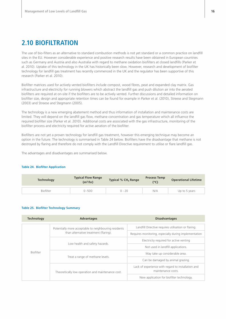
2.10 bIOfILTRaTIOnThe use of bio-filters as an alternative to standard combustion methods is not yet standard or a common practice on landfill sites in the EU. However considerable experience and positive research results have been obtained in European countries such as Germany and Austria and also Australia with regard to methane oxidation biofilters at closed landfills (Parker et al. 2010). Uptake of this technology in the UK has historically been slow. However, research and development of biofilter technology for landfill gas treatment has recently commenced in the UK and the regulator has been supportive of this research (Parker et al. 2010).
Biofilter matrices used for actively vented biofilters include compost, wood fibres, peat and expanded clay matrix. Gas infrastructure and electricity for running blowers which abstract the landfill gas and push dilution air into the aerated biofilters are required at on-site if the biofilters are to be actively vented. Further discussions and detailed information on biofilter size, design and appropriate retention times can be found for example in Parker et al. (2010), Streese and Stegmann (2003) and Streese and Stegmann (2005).
The technology is a new emerging abatement method and thus information of installation and maintenance costs are limited. They will depend on the landfill gas flow, methane concentration and gas temperature which all influence the required biofilter size (Parker et al. 2010). Additional costs are associated with the gas infrastructure, monitoring of the biofilter process and electricity required for active aeration of the biofilter.
Biofilters are not yet a proven technology for landfill gas treatment, however this emerging technique may become an option in the future. The technology is summarised in Table 24 below. Biofilters have the disadvantage that methane is not destroyed by flaring and therefore do not comply with the Landfill Directive requirement to utilise or flare landfill gas.
The advantages and disadvantages are summarised below.
Table 24. Biofilter Application
TechnologyTypical Flow Range
(m3/hr)Typical % CH4 Range
Process Temp
(ºC)Operational Lifetime
Biofilter 0 -500 0 - 20 N/A Up to 5 years
Table 25. Biofilter Technology Summary
Technology Advantages Disadvantages
Biofilter
Potentially more acceptable to neighbouring residentsthan alternative treatment (flaring).
Landfill Directive requires utilisation or flaring.
Requires monitoring, especially during implementation
Low health and safety hazards.Electricity required for active venting
Not used in landfill applications.
Treat a range of methane levels.May take up considerable area.
Can be damaged by animal grazing.
Theoretically low operation and maintenance cost.
Lack of experience with regard to installation and maintenance costs.
New application for biofilter technology.

17Management of Low Levels of Landfill Gas
2.11 In-sITu MeThane OxIdaTIOnMicroorganisms present in the aerobic regions of the landfill cover material will oxidise a proportion of the methane (and other volatile hydrocarbons) to carbon dioxide, a process called biological methane oxidation. The process is a four stage bacteriological conversion of methane into carbon dioxide:
CH4➤
CH3OH➤
HCHO➤
HCOOH➤
CO2
Methane Methanol Methanal Methanoic Acid Carbon Dioxide
Methanotrophic bacteria use these reactions to gain energy and carbon for their growth. Methane oxidation thereby occurs predominantly in the upper 50 cm of soil cover where oxygen ingress is facilitated, and appears to be strongest in the zone 20-30 cm below the surface.
The recommended default value provided by the Intergovernmental Panel on Climate Change Expert Group on Waste is that 10% of methane passing through a landfill cap is oxidised (IPCC, 2006). Estimates of the fraction of landfill gas which could be oxidised by methanotrophic bacteria however range widely dependent both on the assessment methodology and the type of landfill cover. An extensive literature review was carried out on the results of 42 determinations of the fraction of methane oxidised and 30 determinations of methane oxidation rates in a variety of soil types and landfill covers in 2009 (Chanton et al., 2009). This review indicates that the fraction of methane found to be oxidised in field trials is 18% in clayey soils, 34% in organic covers and 53% in sandy soils. The percent oxidation is further an inverse function of the rate of emission. At lower rates, the methanotrophic bacteria in the soil cover can consume a larger portion of the methane delivered to them, oxidizing up to 96 - 100%. Thus in-situ methane oxidation is likely to be an effective management option for low levels of landfill gas with low flows and low methane concentrations.
To optimize landfill covers for methane oxidation it has therefore been suggested to create a functionally layered cover system in which the bottom layer regulates landfill gas flux as a barrier, typically clay soil. The upper layer would function as an oxidation medium working in tandem with the underlying barrier layer (e.g. Stern et al. 2007).
Research undertaken in 2002 indicates that the oxidising capacity of landfill cover in laboratory and field studies is capable of treating approximately 80 to 140 m3/ha/hr of methane with a conversion efficiency of approximately 75% (Defra, 2003).
On landfills which have Landfill Directive compliant low permeability caps fitted, it may be an option to selectively puncture the cap (or otherwise promote gas transport through the surface) once gas generation rates have declined and low-CV management is considered. The gas permeability of the cap could therefore be increased without significantly altering its ability to exclude precipitation and therefore manage leachate generation, enabling bio-oxidation of landfill gas to occur at a controlled rate over a wide area.
In-situ methane oxidation has the disadvantage that methane is not destroyed by flaring and therefore does not comply with the Landfill Directive requirement to utilise or flare landfill gas.

18Management of Low Levels of Landfill Gas
Table 26. In-Situ Methane Oxidation Technology Summary
Technology Advantages Disadvantages
In-situ Methane Oxidation
Does not require gas extraction and gascollection infrastructure.
Cap specifications may not meet requirements of Landfill Directive.
Methane Oxidation works best at lowmethane flows.
Biological Methane Oxidation less effectivethan flaring.Does not require presence of personnel.
Biological Methane Oxidation is likely to vary during the year depending on temperature and
soil moisture.Low maintenance costs.
Total effect difficult to quantify.
2.12 aCTIve and PassIve venTInGPassive venting of landfill gas can be controlled by installing passive venting systems. These may consist of simple venting trenches that release landfill gas into the atmosphere. A more sophisticated passive venting system may consist of a horizontal network of slotted HDPE pipes connected together and fed to vertical venting columns. The columns may be fitted with a rotating aspiromatic cowl to provide a small vacuum and increase the efficiency of the extraction. Passive venting can be used in conjunction with additional treatment measures such as carbon filtration or organic rich compost materials to promote bio-oxidation in vents.
Passive venting has the disadvantage that no biological methane oxidation occurs through the cap nor is methane destructed by flaring and therefore does not comply with the Landfill Directive requirement to utilise or flare landfill gas.
Active venting comprises the forced extraction under suction of landfill gas through gas management infrastructure which is broadly similar to that used for passive venting. The advantages and disadvantages of active venting are identical to those of passive venting although it is likely that a greater proportion of the generated landfill gas will be vented to atmosphere than is the case with passive venting.
Table 27. Active And Passive Venting Technology Summary
Technology Advantages Disadvantages
Active & Passive Venting
Prevents lateral migration. Landfill Directive requires utilisation or flaring.
Limited GHG emission reduction.
Low cost. Limited odour reduction.

19Management of Low Levels of Landfill Gas
3. assessMenT Of besT avaILabLe TeChnIQues
3.1 IdenTIfICaTIOn Of aPPROPRIaTe TeChnOLOGIesA table of potential technologies are provided below, which have been summarised from the available technologies most available on the market.
Table 28. Technology Summary
Technology Methane Content (%) Gas Flow Rate (m3/hr)
Readily Available And Meet EPA Temperature And Retention Requirements.
Conventional HT Flare 30 - 50+ 50 - 2,500+
Modified HT Flares >20 - 50+ 50 - 2,500+
Low-CV Flare 10 - 15 - 25+ 40 - 100+
Intermittent Flaring >20 - 50+ 50 - 100+
Readily Available And Do Not Meet EPA Temperature And Retention Requirements.
Operation Of HT Flares Below 1,000ºC >20 - 50+ 50 - 2,500+
Supported Combustion Flares 0 - 15 50 - 2,500
Open Flares >20 10 - 2,500+
Active and Passive Venting 0 - 100 0 - any
Emerging Technologies
Non-Catalytic Thermal Oxidation 0.4 - 27 500 - 50,000 (at 0.3 - 0.8%)
In-Situ Oxidation 0 - 50 0 - 140 m3/ha/hr
Biofiltration 0 - 20 0 - 500
For many sites which are producing low-CV gas, a generic assessment of the environmental risks associated with the emission of landfill gas may be sufficient as the basis for identification of appropriate low-CV gas management technologies. This is likely to be particularly true for small or low putrescible-fraction sites in remote locations. Key factors to be considered in the assessment would be:
➤➤ Site engineering and geology;
➤➤ Proximity to receptors;
➤➤ Site landfill gas emission rates;
➤➤ Historic site environmental performance, compliance and history of complaints;
➤➤ Quantity of landfill gas abated;
➤➤ Cost of treatment of site emissions;
➤➤ Cost of abatement technology; and
➤➤ Ease of operation, lifetime of technology, automation, flexibility etc.

20Management of Low Levels of Landfill Gas
Larger sites, in proximity to sensitive receptors and sites with a history of complaints may need to undertake additional site-specific assessment to demonstrate environmental risks are appropriately managed by the proposed technology.
Figure 4. Operational Ranges Of Available Low-CV Technologies
Figure 4 is a graphical representation of the typical ranges of applicability of low-CV flaring and other technologies currently available as a function of gas flow rate and methane content. Low-CV technologies effectively follow standard high temperature flaring until methane concentrations reach approximately 15%.
Intermittent operation of either conventional flares or low-CV flares is effectively a means of increasing the instantaneous flow rate by using the landfill itself as a gas reservoir and allowing gas to accumulate until such time as it reaches sufficient flows to be utilised by the system. The challenge with intermittent operation is to balance the extraction rate and duration with the gas generation rate so as not to seriously reduce the methane concentration by over-extraction, or by failing to extract enough gas resulting in unnecessarily high fugitive emissions.
Control of methane emissions by oxidation in the landfill cap or biofiltration appears to be the most appropriate technique for management of landfill gas where methane concentrations are below 10% to 15%, the current effective limit of operation of available low-CV technologies, and for landfill gas with higher methane contents at lower flows. In practice, there is considerable overlap between operational conditions where oxidation and other approaches are valid. However, oxidation in the landfill cap or biofiltration do not comply with the Landfill Directive requirement to utilise or flare landfill gas.
On landfills where high gas flow rates and low methane contents occur, it is likely that there are gas infrastructure management issues which should be addressed prior to consideration of technologies.
Due to the high costs of purchase and operation in the landfill environment, it is difficult to envisage the circumstances in which the currently available catalytic oxidation technologies would provide cost-effective solutions to the management of low-CV landfill gas.

21Management of Low Levels of Landfill Gas
The use of supplementary fuelled flares is likely to have a very limited applicability to the management of low-CV landfill gas. Supplementary fuelled flares are potentially useful in the following situations where the requirement to control odours or lateral migration outweighs the increased GHG emissions produced: in the start up phase of a cell; the management of odours from operational areas; and/or control of lateral migration in proximity to sensitive receptors.
The use of HT enclosed flares outside of their design parameters, open flares, and venting (both passive and active) of landfill gas are technically valid options for the management of low-CV landfill gas. However, these options do not necessarily represent best practice in terms of emissions, compliance with licence conditions and the Landfill Directive.
On sites without existing gas collection infrastructure, there may be significant additional costs associated with the installation and operation of a gas collection system which would typically be in the range €25,000 to €50,000 per hectare, depending on the depth of the waste mass and the type of drilling used. Replacement of approximately 5% to 10% of an installed well field annually could be considered as normal maintenance. The selection of a gas management system for these sites would need to be informed by the completion of a risk assessment.

22Management of Low Levels of Landfill Gas
4. RefeRenCes
Chanton, J.P., Powelson, D. K. and Green, B. R. (2009) Methane Oxidation in Landfill Cover Soils, is a 10% Default Value Reasonable? Journal of Environmental Quality 38, pp. 654-663.
Defra (2003): Methane emissions from Landfill Sites in the UK, Report No. EPG 1/1/145, January 2003.
Defra (2004): Valuation of the external costs and benefits to health and environment of waste management options, December 2004, obtainable from http://www.defra.gov.uk/environment/waste/statistics/documents/costbenefit-valuation.pdf
DoE UK (1997): UK Department of the Environment, Guidance on the Emissions from Different Types of Landfill Gas Flares, Report No. CWM 142/96A.
Environment Agency of England and Wales, (2002): Guidance on landfill gas flaring, November 2002.
Environment Agency of England and Wales (2004): Guidance on gas treatment technologies for landfill gas engines, LFTGN06, September 2004.
Environment Agency of England and Wales (2009): Case study. Cheshire County Council’s use of low calorific flares on closed historic landfill sites.
European Union (1999): Landfill Directive (Council Directive 1999/31/EC).
EPA (2000): Landfill Manuals: Landfill Site Design.
EPA (2008). Hitting the Targets for Biodegradable Municipal Waste: Ten Options for Chance.
EPA (2010): Air Guidance Note – Surface VOC Emissions Monitoring on Landfill Facilities (AG6).
Hall, D.H., Drury, D., Gronow, J.R., Pollard, S.J.T. and Smith, R. (2007): Estimating pollutant removal requirements for landfills in the UK: III. Policy analysis and operational implications. Environmental Technology 28, No. 1, pp. 25-32.
IPCC (2006): Inter-Governmental Panel on Climate Change. Guidelines for national greenhouse gas inventories. Available at http://www.ipcc-nggip.iges.or.jp/public/2006gl/index.html (accessed 09/09/2010).
IPCC (2007), Climate change 2007: the physical science basis. Contribution of Working Group I to the Fourth Assessment Report of the Intergovernmental Panel on Climate Change, Cambridge University Press.
Ministry of Environment, Heritage and Local Government (2006): The National Strategy on Biodegradable Waste.
Parker, T., Pointer, P., Baker, D. and Devoy, M. (2010) Review of design aspects for full-scale aerated biofilters to treat gas from closed landfills. Proceedings Waste 2010.
Ritzkowksi, M., Heyer, K.-U. and Stegmann, R. (2006). Fundamental process and implications during in situ aeration of old landfills. Waste Management 26 (2006), pp. 356-372.
Ritzkowski, M. and Stegmann, R. (2010). Generting CO2-credits through landfill in situ aeration. Waste Management 30 (2010), pp. 702-706.
Stern, J.C., Chanton, J., Abichou, T., Powelson, D., Yuan, L., Escoriza, S. and Bogner, J. (2007) Use of a biologically active cover to reduce landfill methane emissions and enhance methane oxidation. Waste Management 27 (2007), pp. 1248-1258.
Streese and Stegmann (2003): Microbial oxidation of methane from old landfills in biofilters, Waste Management, 23, pp. 573 – 580.

23Management of Low Levels of Landfill Gas
Streese and Stegmann (2005): Potentials and limitations of biofilters for methane oxidation. Proceedings Sardinia 2005, Tenth international waste management and landfill symposium S. Margherita di pula, Cagliari, Italy; 3 - 7 October 2005.
UNFCCC (2009). Approved Baseline and Monitoring Methodology AM0083: avoidance of Landfill Gas Emissions by In-situ aeration of Landfills.
Williams, Ward, R. S. and Noy, D. J., Dynamics of landfill gas migration in unconsolidated sands, Waste Management and Research, 17, No 5, pp. 327-342.

Headquarters, PO Box 3000Johnstown Castle Estate County Wexford, Ireland
Ceanncheathrú, Bosca Poist 3000Eastát Chaisleán Bhaile Sheáin Contae Loch Garman, Éire
T: +353 53 916 0600F: +353 53 916 0699
Regional InspectorateMcCumiskey House, RichviewClonskeagh Road, Dublin 14, Ireland
Cigireacht Réigiúnach, Teach Mhic ChumascaighDea-Radharc, Bóthar Cluain SceachBaile Átha Cliath 14, Éire
T: +353 1 268 0100F: +353 1 268 0199
Regional InspectorateInniscarra, County Cork, Ireland
Cigireacht Réigiúnach, Inis CaraContae Chorcaí, ÉireT: +353 21 487 5540F: +353 21 487 5545
Regional InspectorateJohn Moore Road, CastlebarCounty Mayo, Ireland
Cigireacht Réigiúnach, Bóthar Sheán de MórdhaCaisleán an Bharraigh, Contae Mhaigh Eo, Éire
T: +353 94 904 8400F: +353 94 902 1934
Regional InspectorateSeville Lodge, Callan Road, Kilkenny, Ireland
Cigireacht Réigiúnach, Lóiste Sevilla, Bóthar Challainn, Cill Chainnigh, Éire
T: +353 56 779 6700F: +353 56 779 6798
Regional InspectorateThe Glen, Monaghan, Ireland
Cigireacht Réigiúnach, An GleannMuineachán, Éire
T: +353 47 77600F: +353 47 84987
E: [email protected] W: www.epa.ieLoCall: 1890 33 55 99
Printed on an environmentally friendly paper stock