managing instantly dense hot spot regions in wireless ... · managing instantly dense hot spot...
TRANSCRIPT
Int. J. Advanced Networking and Applications
Volume: 07 Issue: 01 Pages: 2593-2605 (2015) ISSN: 0975-0290
2593
Managing Instantly Dense Hot Spot Regions in
Wireless Cellular Communication Networks Vikas Solanki
Department of Computer Science Engineering & IT, Mangalayatan University (MU), Aligarh (INDIA)
Email: [email protected]
M. Qasim Rafiq
Sr. M IEEE, Professor, Department of Computer Science Engineering & IT, MU, Aligarh (INDIA)
Email: [email protected]
----------------------------------------------------------------------ABSTRACT-----------------------------------------------------------
In a wireless communication cellular network, call activity can be more intensive in some regions than others.
These high-traffic regions are called hot spot regions. In typical deployments of wireless cellular networks, traffic
hot spots can arise from the non-uniform geographic distribution of the mobile users, and the heavy-tailed nature
of their network usage patterns. These hot spots of activity can degrade system performance, by increasing
network utilization, wireless interference, call blocking, and even call dropping from failed handoffs for mobile
users. In this paper, a hierarchical cellular communication wireless network is characterized by overlapping the
service area for managing the new calls users having different mobility speed. The overlapping property of the
hierarchical-network provides the advantages that share the traffic load to improve the performance of wireless
cellular networks in the highly populated area where both slow speed users and high speed users are available.
Picocells are created that are underlaid to two-tier networks for handling the slow or staying speed visitor
(outside registered) users. The hierarchical-networks with picocells, microcells and macrocells provide the
secondary resource, which provide the services to new calls as well as handoff calls with guard channels by
overflow the slow speed visitor users in picocells, slow speed local users in macrocell by sharing the frequency in
vertical as well as in horizontal directions. The picocell is installed on four wheeler vehicle may be moved at any
place as per necessity and may be utilized to create picocell to handle the load of hot spot area. Such kind of
picocell is known as Portable-Picocell (P-Picocell/ P2cell). The call loss probability of new calls is developed
through numerical analysis. The proposed schemes are compared with the existing schemes of CAC. Results show
that new proposed schemes are more efficient and handle more visitor calls by redirecting calls and sharing of
load in P2cell.
Keywords - guard channel, load redirection, macrocell, microcell, P2cell.
------------------------------------------------------------------------------------------------------------------------ -------------------------
Date of Submission: April 26, 2015 Date of Acceptance: June 25, 2015
------------------------------------------------------------------------------------------------------------------------ -------------------------
1. INTRODUCTION
Demand from wireless users is growing rapidly. In order
to provide the efficient, interference-less services against
the huge demand of the wireless cellular communication
networks, without dropping and blocking calls request is
the challenging issue. Beside voice and data services as in
3G, and 4G are expected to provide fully IP-bases services
with higher data rates up to 1Gbps for nomadic / slow
mobility users and 100 Mbps for high mobility users.
Since the existing bandwidth reserved for wireless
networks is limited, methods to improve radio spectrum
efficiency are needed so that higher network capacity can
be achieved.
To release spectrum stress, one way is to design small
size cell. Moreover, small cells are not advantageous in the
service area where user population is sparse with slow and
high speed subscribers. Small cell systems induce an
increase handovers by high speed mobile subscribers.
Micro-macrocell overlay structures can overcome with
these difficulties. . Overlapping property of hierarchical
structure provides the advantages that share traffic load to
improve the efficiency of call admission control (CAC). It
provides the users to access a wireless network service. On
the other hand, these are the decision making part of the
network carriers that provide services to users with
guaranteed quality and achieve maximum possible
resource utilization. It is therefore conceivable that CAC
policy is one of the critical design considerations in any
wireless network. CAC schemes provide the services for
both i.e. new as well as old call users.
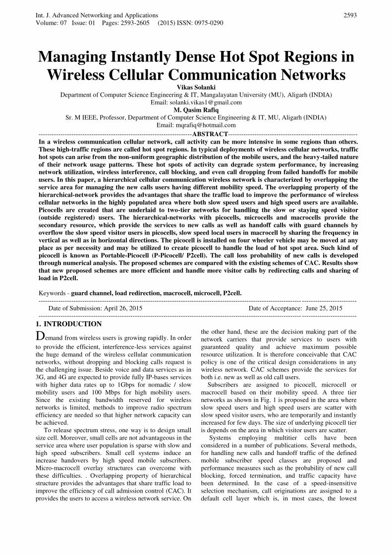
Subscribers are assigned to picocell, microcell or
macrocell based on their mobility speed. A three tier
networks as shown in Fig. 1 is proposed in the area where
slow speed users and high speed users are scatter with
slow speed visitor users, who are temporarily and instantly
increased for few days. The size of underlying picocell tier
is depends on the area in which visitor users are scatter.
Systems employing multitier cells have been
considered in a number of publications. Several methods,
for handling new calls and handoff traffic of the defined
mobile subscriber speed classes are proposed and
performance measures such as the probability of new call
blocking, forced termination, and traffic capacity have
been determined. In the case of a speed-insensitive
selection mechanism, call originations are assigned to a
default cell layer which is, in most cases, the lowest
Int. J. Advanced Networking and Applications
Volume: 07 Issue: 01 Pages: 2593-2605 (2015) ISSN: 0975-0290
2594
(microcell) layer [1-2]. It is proposed to direct a
new/handoff for the appropriate tier based on its previous
speed [3-4]. However, when there is no available channel
on the preferred tier, the call will be directed to the other
(un-preferred) tier. This is called an overflow. If a speed
sensitive selection mechanism is used, arriving calls can
be directed to the specific cell layer that depends on the
speed class of the mobile station. Many works are also
directed in the direction to optimize the performance of the
system based on the factors such as roaming speed of
users, level of cloudiness of an area, location management,
and channel management etc. [5-11].
Macrocell
Microcell
Picocell
Figure 1: A proposed three tier cellular communication network
Two-way overflows are considered in between both tier
and a take-back scheme is also proposed in which call is
redirect from an un-preferred tier to the preferred tier at
the time of handoff take place [12] and a channel
rearrangement scheme is proposed by forcing a handset in
the overlapping area to take an early handoff permanently
[13]. In this paper, a three-tier system is proposed with
Guard-Channels in upper two tiers that are reserved to
handle the handoff calls only. The aim of this work is to
improve the performance of new calls by using
overlapping property of the three-tier system that provides
the advantage to share the traffic load with frequency
sharing techniques in among picocell, microcells and
macrocell. By using the overlapping property of three-tier
system the load of the cell may be transferred from lower
tier to upper tier and vice-versa. Adding capacity in
temporary hot spot area is expensive, time consuming by
splitting the cells due to installation cost. A picocell makes
them a good fit for places needing enhanced capacity [14].
2. PROPOSED STRATEGIES
Let us assume that a macrocell is overlapping with n
microcells, and neighbouring to k macrocells. A microcell
is overlapping with b picocells or in the area where
needed. When a channel request arrives at the macrocell,
and if the macrocell has no free channels, then the system
force one of the slow calls exist in the macrocell to move
into one of the other n overlapping corresponding empty
microcells. On the contrary, when a channel request
arrives at a microcell, and subscriber is visitor user then it
is transferred to picocell, otherwise if the microcell has no
free channels, then it can be either overflow to the
macrocell, or force one of the slow calls exist in the
macrocell to move into one of the other n-1 overlapping
empty microcells. Thus, a channel becomes vacant in the
macrocell and new call can be overflowed to the overlaid
macrocell. It is observed that such frequency sharing
provides lot of flexibilities to shift the load among the
cells on the hierarchical-tiers in vertical direction in which
lowest tier is picocells [15] may be portable installed on
four wheeler vehicle. The proposed networks use
underlaid Portable-Picocell to microcell that is used
proposed scheme Portable-Picocell Overflow with
Vertical Direction Frequency Sharing (P2O-VDFS). In
this paper we are introducing underlaid picocell(s) to
microcell for handling the slow speed visitor subscribers
with proposed two-tier model by Vikas Solanki at. el. [16-
17] in which Virtual Direction Frequency Sharing
(VDFS) and Horizontal Direction Frequency Sharing
(HDFS) schemes are proposed. Proposed two-tier model
restricted fast speed users to overflow in microcell and if
slow speed users overflowed to un-preferred tier then it
will not return automatically, until it forced to overflow
for serving the new/handoff calls in macrocell. In this
system a fast moving calls do not shift to microcells to
avoid more handoff. Thus, overall system can avoid more
call dropping probability. The scheme Horizontal
Direction Frequency Sharing [17] works only in upper-
tier with k neighbouring cells, when VDFS scheme fails
and not able to provide the service for arriving calls. In
[13, 16] some channels are reserved called Guard
Channels, that are used only for providing the services to
handoff calls. Therefore, guard channels can’t be used for serving new call or overflow the new call in un-preferred
tier. The VDFS scheme used prior to HDFS scheme to
share the frequency in upper most two tiers for handling
the traffic load.
The proposed schemes are used underlaid P2cells to
handle the hot spot with the two tier system proposed in
[17]. P2cell does not have any Guard channels and used
allotted frequency only to serve the slow speed new visitor
subscribers who are instantly increased for few days in
specified area (hot spot).
Table 1 shows the redirection of load in different
schemes. Simulation result shows the performance
comparison of conventional schemes and proposed
schemes. We have seen that proposed schemes perform
better.
Table 1: Redirection of load in different schemes
Scheme
Reference
Strategy No. of
redirect
12 Overflow+Take Back 1
13 Rearrange+Overflow k+1
17 VDFS with Guard
channels
n
17 HDFS with Guard
channels
n+k
Proposed P2O-
VDFS VDFS with picocell n+1
Proposed P2O-
HDFS HDFS with picocell n+k+b
Int. J. Advanced Networking and Applications
Volume: 07 Issue: 01 Pages: 2593-2605 (2015) ISSN: 0975-0290
2595
2.1 VDFS and HDFS Strategy
Let us consider that there is a channel request arriving at
the macrocell M or one of n microcells mi. If no channel is
available in the cell to satisfy that request then proposed
VDFS and HDFS strategy will take place, trying to find a
channel for serving the said request [16-17]. The VDFS
strategy tries to find a channel by shifting calls in the
vertical direction, i.e., from one tier to the other tier. When
VDFS strategy fails to serve the request, HDFS strategy
tries to find a channel by shifting calls in the horizontal
direction on the higher tier. Let us consider that some
visitor users are instantly increased in small area for few
days and therefore network becomes saturated. Here we
are proposed a portable picocell underlaid to microcell in
the saturated area to handle the visitor subscribers
instantly increased for few days. In this paper P2O-VDFS
(Portable Picocell Overflow-VDFS) and P2O-HDFS
(Portable Picocell Overflow-HDFS) strategies are
proposed to improve the performance of the network in
area, where some visitor users are increased instantly for
few days. Simulation results shows that the proposed
strategies improve the efficiency of wireless cellular
networks even visitor slow subscribers are increased
instantly in an underlaid picocell area. In the following
sub-sections, we discuss overflow and channel sharing in
vertical as well as horizontal direction for slow
subscribers. The sub-sections describe the P2O-VDFS and
P2O-HDFS strategies for slow subscribers only, and
model uses same strategy for fast subscribers as discussed
in [17].
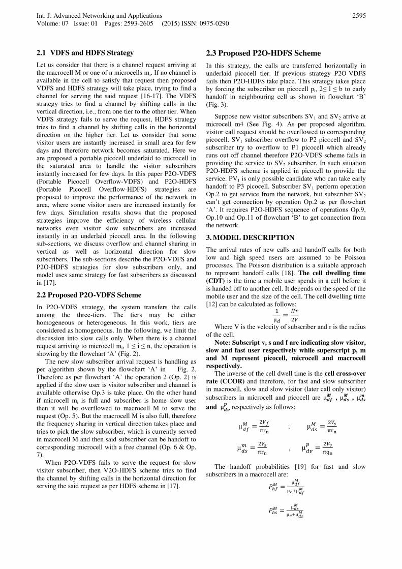
2.2 Proposed P2O-VDFS Scheme
In P2O-VDFS strategy, the system transfers the calls
among the three-tiers. The tiers may be either
homogeneous or heterogeneous. In this work, tiers are
considered as homogeneous. In the following, we limit the
discussion into slow calls only. When there is a channel
request arriving to microcell mi, 1 ≤ i ≤ n, the operation is showing by the flowchart ‘A’ (Fig. 2).
The new slow subscriber arrival request is handling as
per algorithm shown by the flowchart ‘A’ in Fig. 2.
Therefore as per flowchart ‘A’ the operation 2 (Op. 2) is
applied if the slow user is visitor subscriber and channel is
available otherwise Op.3 is take place. On the other hand
if microcell mi is full and subscriber is home slow user
then it will be overflowed to macrocell M to serve the
request (Op. 5). But the macrocell M is also full, therefore
the frequency sharing in vertical direction takes place and
tries to pick the slow subscriber, which is currently served
in macrocell M and then said subscriber can be handoff to
corresponding microcell with a free channel (Op. 6 & Op.
7).
When P2O-VDFS fails to serve the request for slow
visitor subscriber, then V2O-HDFS scheme tries to find
the channel by shifting calls in the horizontal direction for
serving the said request as per HDFS scheme in [17].
2.3 Proposed P2O-HDFS Scheme
In this strategy, the calls are transferred horizontally in
underlaid picocell tier. If previous strategy P2O-VDFS
fails then P2O-HDFS take place. This strategy takes place
by forcing the subscriber on picocell pl, 2≤ l ≤ b to early
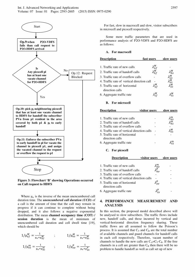
handoff in neighbouring cell as shown in flowchart ‘B’ (Fig. 3).
Suppose new visitor subscribers SV1 and SV2 arrive at
microcell m4 (See Fig. 4). As per proposed algorithm,
visitor call request should be overflowed to corresponding
picocell. SV1 subscriber overflow to P2 picocell and SV2
subscriber try to overflow to P1 picocell which already
runs out off channel therefore P2O-VDFS scheme fails in
providing the service to SV2 subscriber. In such situation
P2O-HDFS scheme is applied in picocell to provide the
service. PV1 is only possible candidate who can take early
handoff to P3 picocell. Subscriber SV1 perform operation
Op.2 to get service from the network, but subscriber SV2
can’t get connection by operation Op.2 as per flowchart
‘A’. It requires P2O-HDFS sequence of operations Op.9,
Op.10 and Op.11 of flowchart ‘B’ to get connection from the network.
3. MODEL DESCRIPTION
The arrival rates of new calls and handoff calls for both
low and high speed users are assumed to be Poisson
processes. The Poisson distribution is a suitable approach
to represent handoff calls [18]. The cell dwelling time
(CDT) is the time a mobile user spends in a cell before it
is handed off to another cell. It depends on the speed of the
mobile user and the size of the cell. The cell dwelling time
[12] can be calculated as follows:
µ = ��
Where V is the velocity of subscriber and r is the radius
of the cell.
Note: Subscript v, s and f are indicating slow visitor,
slow and fast user respectively while superscript p, m
and M represent picocell, microcell and macrocell
respectively.
The inverse of the cell dwell time is the cell cross-over
rate (CCOR) and therefore, for fast and slow subscriber
in macrocell, slow and slow visitor (later call only visitor)
subscribers in microcell and picocell are µ��� , µ�� , µ��
and µ��� respectively as follows:
µ� = �π n ; µ� = �π n
µ = �π n ; µ � = ��π n
The handoff probabilities [19] for fast and slow
subscribers in a macrocell are:
�ℎ� = µ�µ +µ�
�ℎ� = µ�µ +µ�
Int. J. Advanced Networking and Applications
Volume: 07 Issue: 01 Pages: 2593-2605 (2015) ISSN: 0975-0290
2596
Similarly the handoff probability for slow subscriber
in microcell may be calculated as
�ℎ = µµ +µ
and the handoff probability for visitor subscriber in
picocell may be calculated as �ℎ� = µ �µ + µ �
No
Yes
No No
Yes Yes
Yes es
No
No
No
No N
Yes Yes
Is
P2cell is
available
Op.1:Arrival of new
call request in mi
Is
Channel
available in Pl picocell
Start
Op.2:Assign the channel in Pl to the
request
End
Is
Channel
available in M
macrocell
Op.5: Overflow the
request & assign the
channel in M to the
request
Op.6: Pick any slow user call
in M such that call’s corresponding microcell mj to vacate the channel in M
Op.7: Overflow the request
in M macrocell
Is
Channel
available in any
mj microcell
Op.8: Call Blocked or use
HDFS scheme(if
available)
Is
Channel
available in
mi microcell
Op.3:Call Blocked or use
P2O-HDFS scheme(if
available)
Is
Subscriber a
visitor user
with vel. Less
than 2
Op.4: Assign the
channel in mi to the
request
Figure 2: Flowchart ‘A’ showing Operations occurred on Call request by slow subscribers arrived to microcell
Int. J. Advanced Networking and Applications
Volume: 07 Issue: 01 Pages: 2593-2605 (2015) ISSN: 0975-0290
2597
No
Yes
Figure 3: Flowchart ‘B’ showing Operations occurred on Call request to HDFS
Where µ is the inverse of the mean unencumbered call
duration time. The unencumbered call duration (UCD) of
a call is the amount of time that the call may remain in
progress if it can continue to complete without being
dropped, and it also follows a negative exponential
distribution. The mean channel occupancy time (COT) /
session duration is the mean of minimum of
unencumbered call duration and cell dwell time [19],
which should be
1/µ� = µ +µ� ; 1/µ� = µ +µ�
1/µ = µ +µ ; 1/µ � = µ +µ ��
For fast, slow in macrocell and slow, visitor subscribers
in microcell and picocell respectively.
Some more traffic parameters that are used in
performance analysis of P2O-VDFS and P2O-HDFS are
as follows:
A. For macrocell
Description fast users slow users
1. Traffic rate of new calls �� -
2. Traffic rate of handoff calls �ℎ� �ℎ�
3. Traffic rate of overflow calls - ��
4. Traffic rate of vertical direction call - ���
5. Traffic rate of horizontal ��� ���
direction calls
6. Aggregate traffic rate �� ��
B. For microcell
Description visitor users slow users
1. Traffic rate of new calls - �
2. Traffic rate of handoff calls - �ℎ
3. Traffic rate of overflow calls - -
4. Traffic rate of vertical direction calls - ���
5. Traffic rate of horizontal - -
direction calls
6. Aggregate traffic rate - �
C. For picocell
Description visitor users slow users
1. Traffic rate of new calls � � -
2. Traffic rate of handoff calls �ℎ� -
3. Traffic rate of overflow calls - -
4. Traffic rate of vertical direction calls - -
5. Traffic rate of horizontal ��� -
direction calls
6. Aggregate traffic rate � � -
4. PERFORMANCE MEASUREMENT AND
ANALYSIS
In this section, the proposed model described above will
be analysed to slow subscribers. The traffic flows include
new, handoff calls, and those incurred by vertical and
vertical-horizontal direction frequency sharing. These
traffic flows are all assumed to follow the Poisson’s
process. It is assumed that CT and CR are the total number
of available channels and guard channels for handoff calls
in each cell respectively. Therefore, vacant number of
channels to handle the new calls are CA=CT-CR. If the free
channels in a cell are greater than CR then there will be no
problem to handle handoff as well as call set up of new
Start
Op.10: pick pl neighbouring picocell
that has at least one vacate channel
to HDFS for handoff the subscriber
PVn from p1 resident in the area
covered by both p1 & pl to early
handoff
Op.9:when P2O-VDFS
fails than call request to
P2O-HDFS arrived
Is
Any picocell pl
has at least one
vacate channel
for P2O-HDFS
Op.11: Enforce the subscriber PVn
to early handoff in pl for vacate the
channel in picocell p1, and assign
the vacated channel to the request
or overflow the request to p1
Op.12: Request
Blocked
Stop
Int. J. Advanced Networking and Applications
Volume: 07 Issue: 01 Pages: 2593-2605 (2015) ISSN: 0975-0290
2598
Macrocell
PS6
S4 PS10
PS2 PS3
Slow User S2 Microcell
Fast User
: Representing, cell has free channel(S) SV1
: Representing, cell is fully occupied PS5 SV2 PV1 PV2 PS4
SVn: Visitor Call request Picocell
PVn: Present visitor subscriber PV3
Sn: Call request Figure 4: Channel sharing in the horizontal direction for visitor slow subscribers PSn: Present subscriber
calls. But, if any cell has less or equal number of channels
than CR, a free channel performing only handoff and
though new calls, or overflow the slow speed users/forced
handoff in upper/lower tier are handled by proposed P2O-
VDFS and/or P2O-HDFS schemes for better CAC to
improve the performance of cellular networks.
4.1 Performance of Proposed P2O-VDFS Scheme
The target is to give the efficient scheme for handling the
slow speed new calls in the area, where some visitors are
increased instantly for few days, so that system will reduce
the call lose probability of slow speed new calls.
Therefore, the calls lose probabilities � and � � of new
calls for slow and visitor subscribers respectively are
derived. These are the probability for a channel request
being refused after the P2O-VDFS.
Therefore call loss probabilities are:
� = � ����
� � = �
Where �� is the failure probability of sharing the
vertical direction
�� = 1 − � � 1 − � (1)
Where (1 − � ) is the probability of microcell has at
least one free channel and � � is the probability having a
slow subscriber that is currently served by the macrocell
and also covered by the microcell to be served them. � � = 1 − − ��� 1 − � (2)
Where − ��� 1 − � represents the probability of
all slow subscriber serving in macrocell are not located in
this particular microcell and � is the probability of slow
subscribers located in the macrocell for the same area.
The ��, � and � are the probabilities that a mobile
subscriber has no free channel in a macrocell and
microcell and picocell respectively.
�� =��µ� +��µ� ���
���!∑ ��µ� +��µ�
!���=0 (3)
P1 P2 P3
PS4
m3
m2
PS1 m1
S1
m4
PS7 PS8
S2 S3
PS9
Int. J. Advanced Networking and Applications
Volume: 07 Issue: 01 Pages: 2593-2605 (2015) ISSN: 0975-0290
2599
� = �µ ���� !∑ �µ !��=0
(4)
� = � ��µ �� ������!∑ � ��µ �� !���=0
(5)
Here ��µ� + ��µ� ,
�µ and � ��µ �� are the traffics
contributed by the subscribers on macrocell, microcell and
picocell respectively for available channels.
Let variables �� , �� , � and � � denotes the arrival
rates and µ� , µ� , µ , and µ � , denotes the service rates.
Next, it is need to calculate the aggregate traffic �� , �� , � and � � by analysis model [20]. These traffics are
composed of new calls, handoff calls, overflow calls, and
channel sharing calls. Variable �� is aggregate traffic rate
incurred by new calls and handoff calls into macrocell by
the fast subscribers:
�� = �� + �ℎ�
Where �ℎ� = �� 1 − �� �ℎ�
Here �ℎ� means the handoff rate, is the aggregate
traffic rate itself successfully stays in the macrocell �� 1 − �� times with the handoff probability �ℎ� .
Similarly, �� is the aggregate traffic rate incurred by
overflow calls and handoff calls into a macrocell by slow
mobile subscribers. �� = �� + �ℎ�
Where �� = �� �
Here �� means the overflow rate incurred by overflow
from the n microcells covered by the macrocell and �ℎ� is
the handoff calls into a macrocell by slow mobile
subscribers, which equals the slow subscribers
successfully staying on the high tier �� 1 − �� times the
handoff probability �ℎ� , that is
�ℎ� = �� 1 − �� �ℎ�
The traffic rate of � is incurred by new calls, handoff
calls, and calls caused by channel-sharing for slow
subscribers: � = � + �ℎ + ��
Where �ℎ is the handoff calls equals the slow
subscriber successfully handoff on lower tier �ℎ = � 1 − � �ℎ and �� is caused by vertical direction frequency sharing
strategy, �� = ���� ���� + �� � �
Here ��� is the load caused by the vertical direction
frequency sharing by slow subscriber in the physical area
covered by a macrocell (including one macrocell and n
microcell) and � � times is the probability that a
subscriber in macrocell can be rearranged to a microcell
but only a fraction 1/n of the load will be injected to the
microcell. The rate ��� can be derived as follows: ��� = � � + �ℎ � ��,
It equals the new call arrival rate and handoff call
rate of slow subscribers into the n microcells � � +�ℎ , � is times probability that they see no free channel
in the local microcell, and �� times probability that they
see no free channel in the macrocell.
Finally the term ����+�� is the ratio of vertical
direction frequency sharing flows by slow subscribers into
microcells.
The traffic rate of � � is incurred by new calls, and
handoff calls for visitor subscribers: � � = � � + �ℎ�
Where �ℎ� is the handoff calls equals the visitor
subscribers successfully handoff on lower tier �ℎ� = � � 1 − � �ℎ�
4.2 Performance of Proposed P2O-HDFS Scheme
In this section, analysis is made of the proposed P2O-
HDFS scheme. If some visitor mobile subscribers are
increased instantly for few days in a particular place then
microcell may be exhausted and therefore proposed
scheme VDFS in [16-17] may be helpless in handling the
load with QoS. If a visitor mobile subscriber call request
found no free channel in its local cell then previously
discussed scheme P2O-VDFS fail to perform, and P2O-
HDFS scheme take place. The goal is to drive the calls
lose probabilities � and � � of new calls for slow and
visitor subscribers respectively.
The call loss probabilities are: � = � ���� ��
Int. J. Advanced Networking and Applications
Volume: 07 Issue: 01 Pages: 2593-2605 (2015) ISSN: 0975-0290
2600
� � = � ��
Where probability�� is the failure probability of vertical
direction sharing as given in (1), and �� , �� are the failure
probabilities of horizontal direction sharing in Macrocell
and Picocell respectively is as follows: �� = 1 − �� 1 − �� 1 − ��′ �� = 1- � (1 − � )
Where �� ′ is the failure probability of vertical direction
sharing for macrocell Mi as given in (1), and �� , � are
the probabilities for staying at least one subscriber in early
handoff area in macrocell and picocell respectively given
as: �� = 1 − � � ���
� = 1- 2 2 ���
��, � , and � can be derived as (3), (4) and (5)
respectively, but their values are different for different
aggregate traffic rates. The horizontal direction sharing
affects only traffic flows on macrocell, and picocell
therefore � in microcell are same as that in the vertical
direction frequency sharing as discussed in section 4.1, but
their values are dependent on ��, and � in macrocell and � in picocell when derived as for horizontal direction
sharing.
In macrocell, the aggregate rate �� incurred by new
calls, handoff calls, and horizontal direction sharing calls
for fast subscriber: �� = �� +�ℎ� + ��� ��� caused by horizontal direction sharing can be
calculated as:
��� = (�� + �ℎ� )���� ��
It equals the new call arrival rate and handoff rate into
macrocell �� + �ℎ� , times probability that they found
no free channel in the macrocell��, times probability that
they fail in vertical direction sharing�� , and times
probability that at least one subscriber staying in early
handoff area�� . Similarly �� is the aggregate traffic rate
incurred by overflow calls, handoff calls, and horizontal
direction sharing in macrocell by slow subscribers: �� = �� + �ℎ� + ���
Where ��� is horizontal direction sharing by slow
subscriber,
��� = � � + �ℎ � ���� ��
which equals the new call arrival rate and handoff rate
of slow subscribers into the n microcells � � + �ℎ ,
times the probabilities that they found no free channel in
the local microcell � , and neither in the macrocell ��,
times the probability that they fail in vertical direction
sharing �� , and times probability that at least one
subscriber staying in early handoff area �� .
In picocell, the aggregate rate � � incurred by new
calls, handoff calls, and horizontal direction sharing calls
for visitor subscriber:
� � = � �+�ℎ� + ���
��� caused by horizontal direction sharing can be
calculated as: ��� = (� � + �ℎ�)� �
It equals the new call arrival rate and handoff rate into
picocell � � + �ℎ� , times probability that they found no
free channel in the picocell� , and times probability that
at least one subscriber staying in early handoff area � .
5.NNUMERICAL EXAMPLES AND
DISCUSSION
We consider 6 cases denoted from (a) to (f) for
comparison as follows:
a) The call loses probabilities of Take Back (TB)
scheme in reference [12] for slow subscribers are
denoted by ��� ���.
b) The call loses probabilities of Channel
Rearrangement (CR) scheme in reference [13]
for slow subscribers are denoted by ���� ���.
c) The call loses probabilities of Vertical Direction
Frequency Sharing (VDFS) scheme in reference
[17] for slow subscribers are denoted by �������� .
d) The call loses probabilities of Horizontal
Direction Frequency Sharing (HDFS) scheme
in reference [17] for slow subscribers are
denoted by �������� �� .
e) The call loses probabilities of P2O-Vertical
Direction Frequency Sharing (P2O-VDFS)
scheme for slow subscribers are denoted by �������� ��� or (� .� � ).
f) The call loses probabilities of P2O-Horizontal
Direction Frequency Sharing (P2O-HDFS)
scheme for slow subscribers are denoted by �������� �� ������ or (� .� � ).
It is assumed that the total traffic to the entire area
follows the Poisson process with the rate λ and the fraction � + �′ of this traffic from slow mobile subscribers (q for
slow and �′ for visitor subscribers). In [17], the
performance of VDFS and HDFS had been calculated for
Pvs = 0.500095(assumed), but in this paper we are
calculating the performance of VDFS, HDFS and
proposed schemes using the (1).
To compare the different strategies listed (a) to (f), we
assumed some parameters as shown in Table 2.
Int. J. Advanced Networking and Applications
Volume: 07 Issue: 01 Pages: 2593-2605 (2015) ISSN: 0975-0290
2601
Table 2: List of parameters taken for performance
comparison
S.No Parameter
name Value
Macrocell Microcell Picocell
1 Radius 800 m 400 m 250 m
2 Average
velocity 40 km/hr 4km/hr 1km/hr
3 The call
arrival rate
of slow
subscriber
qλ qλ/n �′λ/nb
4 The call
arrival rate
of fast
subscriber
(1 – q – �′)λ 0 0
5 Number of
channels 37 9 7
6 Guard
channels 8 2 0
Here q and �′ are tune the amount of slow and
slow visitor subscribers respectively in an area. n and b
takes care of size difference between macrocell and
microcell and microcell and picocell respectively. Here
assume that n=4, b=4, q=0.5, �′=0.2and the mean holding
time for a call is 140 seconds.
Table 3: Number of assumed channels in the different
schemes to be compared
S.N
o Schem
e
Guard
Channels
(picocell,
microcell,
macrocell)
Available number of
channels- CA for new calls Picocell Microcell Macrocell
1 TB
schem
e
Φ,0,0 Φ 9 37
2 CR
schem
e
Φ,0,0 Φ 9 37
3 VDFS Φ,2,8 Φ 7 29
4 HDFS Φ,2,8 Φ 7 29
5 P2O-
VDFS
0,2,8 7 7 29
6 P2O-
HDFS
0,2,8 7 7 29
To different schemes as mentioned above from (a) to
(f), the call loss probability is calculated and compared in
Fig. 5 and Fig. 6 for slow subscribers. It is assumed that
for fast and slow subscribers, the available number of
channels in the cell is as shown in Table 3. Because first
four schemes in the Table 3 have not any picocell,
therefore number of channels and guard channels are
represented by Φ.
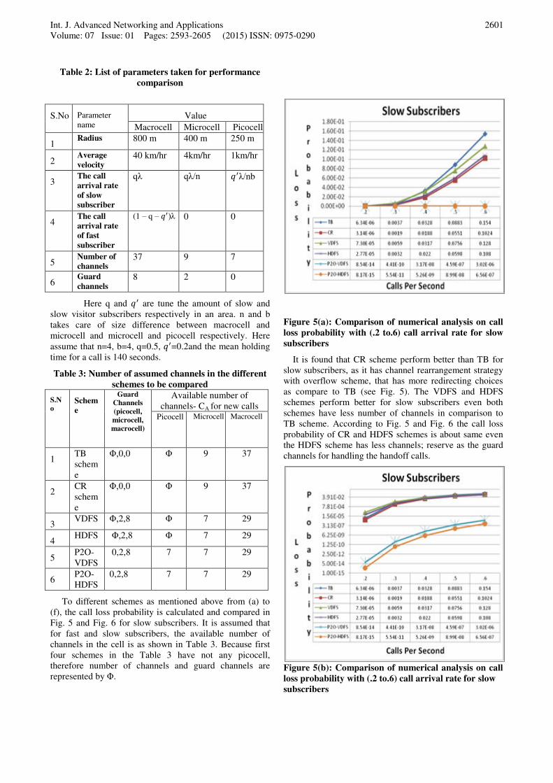
Figure 5(a): Comparison of numerical analysis on call
loss probability with (.2 to.6) call arrival rate for slow
subscribers
It is found that CR scheme perform better than TB for
slow subscribers, as it has channel rearrangement strategy
with overflow scheme, that has more redirecting choices
as compare to TB (see Fig. 5). The VDFS and HDFS
schemes perform better for slow subscribers even both
schemes have less number of channels in comparison to
TB scheme. According to Fig. 5 and Fig. 6 the call loss
probability of CR and HDFS schemes is about same even
the HDFS scheme has less channels; reserve as the guard
channels for handling the handoff calls.
Figure 5(b): Comparison of numerical analysis on call
loss probability with (.2 to.6) call arrival rate for slow
subscribers
Int. J. Advanced Networking and Applications
Volume: 07 Issue: 01 Pages: 2593-2605 (2015) ISSN: 0975-0290
2602
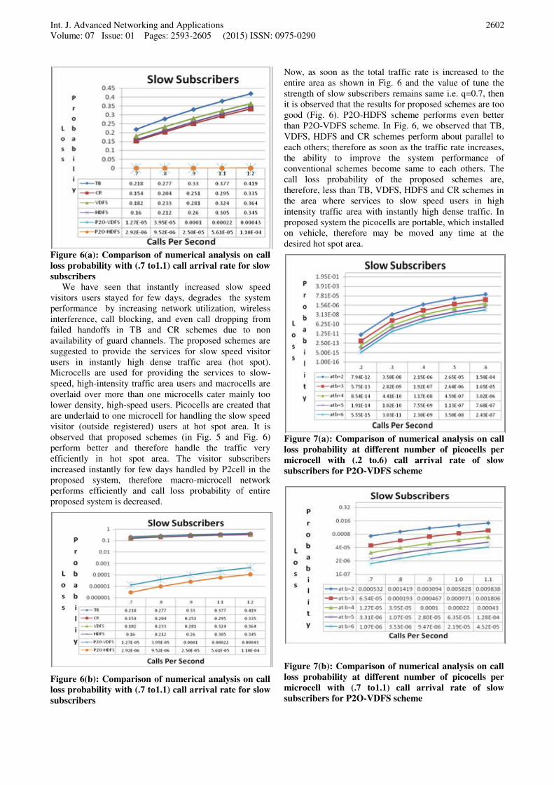
Figure 6(a): Comparison of numerical analysis on call
loss probability with (.7 to1.1) call arrival rate for slow
subscribers
We have seen that instantly increased slow speed
visitors users stayed for few days, degrades the system
performance by increasing network utilization, wireless
interference, call blocking, and even call dropping from
failed handoffs in TB and CR schemes due to non
availability of guard channels. The proposed schemes are
suggested to provide the services for slow speed visitor
users in instantly high dense traffic area (hot spot).
Microcells are used for providing the services to slow-
speed, high-intensity traffic area users and macrocells are
overlaid over more than one microcells cater mainly too
lower density, high-speed users. Picocells are created that
are underlaid to one microcell for handling the slow speed
visitor (outside registered) users at hot spot area. It is
observed that proposed schemes (in Fig. 5 and Fig. 6)
perform better and therefore handle the traffic very
efficiently in hot spot area. The visitor subscribers
increased instantly for few days handled by P2cell in the
proposed system, therefore macro-microcell network
performs efficiently and call loss probability of entire
proposed system is decreased.
Figure 6(b): Comparison of numerical analysis on call
loss probability with (.7 to1.1) call arrival rate for slow
subscribers
Now, as soon as the total traffic rate is increased to the
entire area as shown in Fig. 6 and the value of tune the
strength of slow subscribers remains same i.e. q=0.7, then
it is observed that the results for proposed schemes are too
good (Fig. 6). P2O-HDFS scheme performs even better
than P2O-VDFS scheme. In Fig. 6, we observed that TB,
VDFS, HDFS and CR schemes perform about parallel to
each others; therefore as soon as the traffic rate increases,
the ability to improve the system performance of
conventional schemes become same to each others. The
call loss probability of the proposed schemes are,
therefore, less than TB, VDFS, HDFS and CR schemes in
the area where services to slow speed users in high
intensity traffic area with instantly high dense traffic. In
proposed system the picocells are portable, which installed
on vehicle, therefore may be moved any time at the
desired hot spot area.
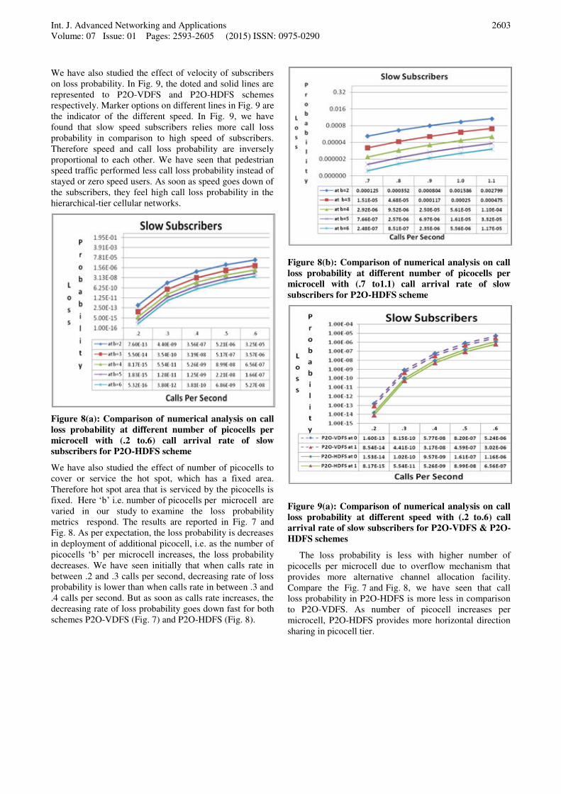
Figure 7(a): Comparison of numerical analysis on call
loss probability at different number of picocells per
microcell with (.2 to.6) call arrival rate of slow
subscribers for P2O-VDFS scheme
Figure 7(b): Comparison of numerical analysis on call
loss probability at different number of picocells per
microcell with (.7 to1.1) call arrival rate of slow
subscribers for P2O-VDFS scheme
Int. J. Advanced Networking and Applications
Volume: 07 Issue: 01 Pages: 2593-2605 (2015) ISSN: 0975-0290
2603
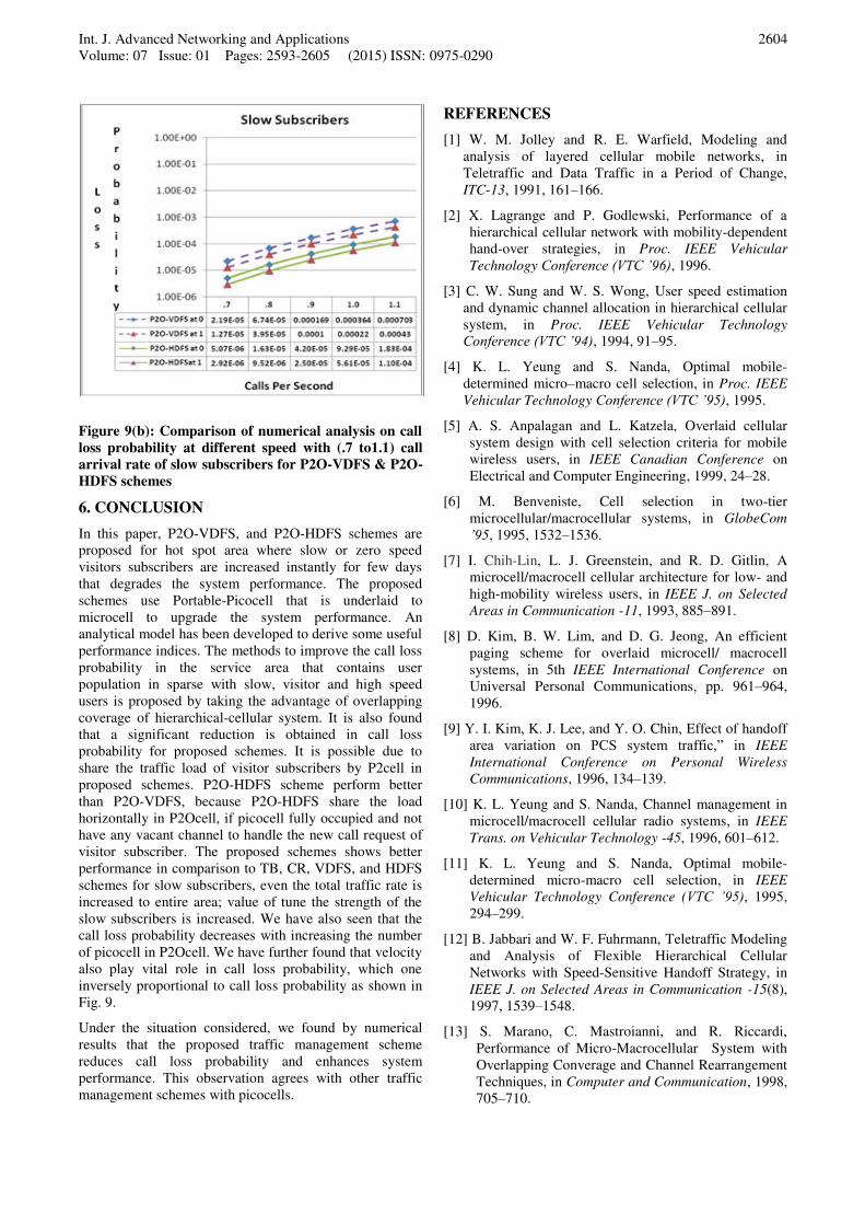
We have also studied the effect of velocity of subscribers
on loss probability. In Fig. 9, the doted and solid lines are
represented to P2O-VDFS and P2O-HDFS schemes
respectively. Marker options on different lines in Fig. 9 are
the indicator of the different speed. In Fig. 9, we have
found that slow speed subscribers relies more call loss
probability in comparison to high speed of subscribers.
Therefore speed and call loss probability are inversely
proportional to each other. We have seen that pedestrian
speed traffic performed less call loss probability instead of
stayed or zero speed users. As soon as speed goes down of
the subscribers, they feel high call loss probability in the
hierarchical-tier cellular networks.
Figure 8(a): Comparison of numerical analysis on call
loss probability at different number of picocells per
microcell with (.2 to.6) call arrival rate of slow
subscribers for P2O-HDFS scheme
We have also studied the effect of number of picocells to
cover or service the hot spot, which has a fixed area.
Therefore hot spot area that is serviced by the picocells is
fixed. Here ‘b’ i.e. number of picocells per microcell are varied in our study to examine the loss probability
metrics respond. The results are reported in Fig. 7 and
Fig. 8. As per expectation, the loss probability is decreases
in deployment of additional picocell, i.e. as the number of
picocells ‘b’ per microcell increases, the loss probability
decreases. We have seen initially that when calls rate in
between .2 and .3 calls per second, decreasing rate of loss
probability is lower than when calls rate in between .3 and
.4 calls per second. But as soon as calls rate increases, the
decreasing rate of loss probability goes down fast for both
schemes P2O-VDFS (Fig. 7) and P2O-HDFS (Fig. 8).
Figure 8(b): Comparison of numerical analysis on call
loss probability at different number of picocells per
microcell with (.7 to1.1) call arrival rate of slow
subscribers for P2O-HDFS scheme
Figure 9(a): Comparison of numerical analysis on call
loss probability at different speed with (.2 to.6) call
arrival rate of slow subscribers for P2O-VDFS & P2O-
HDFS schemes
The loss probability is less with higher number of
picocells per microcell due to overflow mechanism that
provides more alternative channel allocation facility.
Compare the Fig. 7 and Fig. 8, we have seen that call
loss probability in P2O-HDFS is more less in comparison
to P2O-VDFS. As number of picocell increases per
microcell, P2O-HDFS provides more horizontal direction
sharing in picocell tier.
Int. J. Advanced Networking and Applications
Volume: 07 Issue: 01 Pages: 2593-2605 (2015) ISSN: 0975-0290
2604
Figure 9(b): Comparison of numerical analysis on call
loss probability at different speed with (.7 to1.1) call
arrival rate of slow subscribers for P2O-VDFS & P2O-
HDFS schemes
6. CONCLUSION
In this paper, P2O-VDFS, and P2O-HDFS schemes are
proposed for hot spot area where slow or zero speed
visitors subscribers are increased instantly for few days
that degrades the system performance. The proposed
schemes use Portable-Picocell that is underlaid to
microcell to upgrade the system performance. An
analytical model has been developed to derive some useful
performance indices. The methods to improve the call loss
probability in the service area that contains user
population in sparse with slow, visitor and high speed
users is proposed by taking the advantage of overlapping
coverage of hierarchical-cellular system. It is also found
that a significant reduction is obtained in call loss
probability for proposed schemes. It is possible due to
share the traffic load of visitor subscribers by P2cell in
proposed schemes. P2O-HDFS scheme perform better
than P2O-VDFS, because P2O-HDFS share the load
horizontally in P2Ocell, if picocell fully occupied and not
have any vacant channel to handle the new call request of
visitor subscriber. The proposed schemes shows better
performance in comparison to TB, CR, VDFS, and HDFS
schemes for slow subscribers, even the total traffic rate is
increased to entire area; value of tune the strength of the
slow subscribers is increased. We have also seen that the
call loss probability decreases with increasing the number
of picocell in P2Ocell. We have further found that velocity
also play vital role in call loss probability, which one
inversely proportional to call loss probability as shown in
Fig. 9.
Under the situation considered, we found by numerical
results that the proposed traffic management scheme
reduces call loss probability and enhances system
performance. This observation agrees with other traffic
management schemes with picocells.
REFERENCES
[1] W. M. Jolley and R. E. Warfield, Modeling and
analysis of layered cellular mobile networks, in
Teletraffic and Data Traffic in a Period of Change,
ITC-13, 1991, 161–166.
[2] X. Lagrange and P. Godlewski, Performance of a
hierarchical cellular network with mobility-dependent
hand-over strategies, in Proc. IEEE Vehicular
Technology Conference (VTC ’96), 1996. [3] C. W. Sung and W. S. Wong, User speed estimation
and dynamic channel allocation in hierarchical cellular
system, in Proc. IEEE Vehicular Technology
Conference (VTC ’94), 1994, 91–95.
[4] K. L. Yeung and S. Nanda, Optimal mobile-
determined micro–macro cell selection, in Proc. IEEE
Vehicular Technology Conference (VTC ’95), 1995.
[5] A. S. Anpalagan and L. Katzela, Overlaid cellular
system design with cell selection criteria for mobile
wireless users, in IEEE Canadian Conference on
Electrical and Computer Engineering, 1999, 24–28.
[6] M. Benveniste, Cell selection in two-tier
microcellular/macrocellular systems, in GlobeCom
’95, 1995, 1532–1536.
[7] I. Chih-Lin, L. J. Greenstein, and R. D. Gitlin, A
microcell/macrocell cellular architecture for low- and
high-mobility wireless users, in IEEE J. on Selected
Areas in Communication -11, 1993, 885–891.
[8] D. Kim, B. W. Lim, and D. G. Jeong, An efficient
paging scheme for overlaid microcell/ macrocell
systems, in 5th IEEE International Conference on
Universal Personal Communications, pp. 961–964,
1996.
[9] Y. I. Kim, K. J. Lee, and Y. O. Chin, Effect of handoff
area variation on PCS system traffic,” in IEEE
International Conference on Personal Wireless
Communications, 1996, 134–139.
[10] K. L. Yeung and S. Nanda, Channel management in
microcell/macrocell cellular radio systems, in IEEE
Trans. on Vehicular Technology -45, 1996, 601–612.
[11] K. L. Yeung and S. Nanda, Optimal mobile-
determined micro-macro cell selection, in IEEE
Vehicular Technology Conference (VTC ’95), 1995,
294–299.
[12] B. Jabbari and W. F. Fuhrmann, Teletraffic Modeling
and Analysis of Flexible Hierarchical Cellular
Networks with Speed-Sensitive Handoff Strategy, in
IEEE J. on Selected Areas in Communication -15(8),
1997, 1539–1548.
[13] S. Marano, C. Mastroianni, and R. Riccardi,
Performance of Micro-Macrocellular System with
Overlapping Converage and Channel Rearrangement
Techniques, in Computer and Communication, 1998,
705–710.
Int. J. Advanced Networking and Applications
Volume: 07 Issue: 01 Pages: 2593-2605 (2015) ISSN: 0975-0290
2605
[14]. Jingxiang Luo and Carey Williamson, Managing
Hotspot Regions in Wireless/Cellular Networks with
Partial Coverage Picocells, in Proceedings of the 6th
ACM international conference, 2008, dl.acm.org.
[15]. R. K. Jain, Sumit Katiyar and N. K. Agrawal,
Hierarchical Cellular Structures in High-Capacity
Cellular Communication Systems, in International
Journal of Advanced Computer Science and
Applications, 2( 9), 2011, 51-57.
[16] Vikas Solanki et.at., Improving the Performance of
Handoff Calls using Frequency Sharing, IJMNCT,
2(4), August 2012, 71-96.
[17] Vikas Solanki, M. Qasim Rafiq, Improving the
Efficiency of Call Admission Control in Wireless
Cellular Communication Networks by Frequency
Sharing Techniques, IJCTT, 9(3), March 2014, 133-
146.
[18] M. A. Farahani and M. Guizani, Markov Modulated
Poisson Process Model for Hand-off Calls in
Cellular Systems, in IEEE Wireless Communications
and Networking Conference (WCNC), 2000.
[19] B. Jabbari, Teletraffic aspects of evolving and next
generation wireless communication networks, in
IEEE Personal Communications, 1996, 4–9.
[20] F. Vanhaverbeke, M. Moeneclaey, and H. Sari,
Increasing cdma capacity using multiple orthogonal
spreading sequence sets and successive interference
cancellation, in IEEE International Conference on
Communications, 3, 2002, 1516-1520.
Biographies and Photographs
Mr. Vikas Solanki is
Assistant Professor and
Incharge in Computer
Science Engineering
and IT department, IET,
at Mangalayatan
University, Aligarh. He
has joined the
university in Oct. 2007.
He did M.Tech. in
Computer Science Engineering and has vast 16 years
teaching experience. He is also pursuing Ph.D. under the
supervision of Prof. M. Qasim Rafiq. He has also 7 years
research experience and published more than 17 research
papers in different international/ national journals/
conferences. He is paper setter and examiner in different
central/ state government/ private university. He is also
awarded as the best teaching faculty member of the
university by the Vice-Chancellor, Mangalayatan
University, Aligarh. He is also involved in different
administrative work, coordinator of university
examination, member of anti ragging squad. He was
Senior Superintendent of DBRAU, Agra Examination-
2006-07 for the center BSA College, Mathura.
Prof. M. Qasim Rafiq is
currently serving as a
Professor and Head in the
Department of Computer
Science Engineering and IT,
IET at Mangalayatan
University, Aligarh. He is
retired Professor and
Chairman of Department
of
Computer Engineering, Aligarh Muslim University,
Aligarh. He has received B.Sc.-Engg.(Electrical), M.Sc.
Engg. (Instrumentation), M.Tech.(CSE) from AMU,
Aligarh and Ph.D.(Computer Engineering) from IIT,
Roorkee in 1996. He is a senior member of IEEE (USA),
life member of Computer Society of India and fellow of
Institution of Electronics and Telecommunication
Engineering, Institution of Engineers (India). . He has
more than 20 years research experience and published
about 50 research papers in different international/
national journals/ conferences and registered 2 patents
also. He guided six Ph.D. scholars and currently
supervising 4 scholars.