manak bhavan, 9 bahadur shah za far marg, new delhi 110002 …10891)_26102016.pdf · manak bhavan,...
TRANSCRIPT

MANAK BHAVAN, 9 BAHADUR SHAH ZAFAR MARG, NEW DELHI 110002
हमारा सदभ : सीईडी 2:2/टी-90 25 10 2016
त ाीीा सिमित : सीमट और ार ट विषय सिमित, सीईडी, 2
रा त ाताभ :
िसविल इजीिीयरी विाग पररष ा चि रखी िाल सद य सीईडी 2 ा सी सदस य
चि रखी िाल अय िीााय
महोदय(य),
निनििखित नानि न नाौद नौखिनह:
रलख स या शीषभा
सीईडी CED 2 (10891)WC IS 1199: ार ट ा ीमी एि विलषण पधितया नजनन रीटन नएयरन टटन नननिनारण - भनगन4
पयननइौनानि न नाौद न ननअवखो िन रनऔरनअपिीनौनान य नयहनत न नहएएनभ ज नि नयि नय नानि न नपनानर निि नहोन ोनइिनपरनअाखन रि नानआप ननयवौनयनअववनन नरोतनरनाननयनन िािनइयननआनौ ीनह
ौनान यननभ जि न ीनअन ानन थवन25 ददसबर 1026
ौनान नयि न ो नहोन ोन पयनन[email protected], [email protected]. पर ा खन र नन
यि न ो न ौनान न रनन न िह न हो ीन ह न अववनन ौनान न ान वखन भनषनन ौनतनन ीन टएिटन हए न ोन रपरोन न रख तन ोनयवनव नअन ानपनि यननजनएगनन नयि नौमनान न िी ीनर न न ीनहए न ोन षवषयनौिान न नअयनय न नपरनािानौ नअववननरि ीनइचनछननपरनआग न ीन नयावनह न निखएनषवषयनौिान न ोनभ ज नजनि न नतन नरख तन ोनअन ानपन नि यननजनएगनन
यहनरख तनभनर ीयनानि नयरोन ीनव तौनइटनपरनभीनह न न
ननयवन न भव य,
(बी ा िसहा) ौखि : रपररनखित राएतन(िौषवखनइजीनियर )
व यापा पररिाली मस दा

MANAK BHAVAN, 9 BAHADUR SHAH ZAFAR MARG, NEW DELHI 110002
DOCUMENT DESPATCH ADVICE
TECHNICAL COMMITTEE: Cement and Concrete Sectional Committee, CED 2
ADDRESSED TO: 1. All Members of Civil Engineering Division Council, CEDC
2. All Members of CED 2,
3. All others interested
Dear Sir (s), Please find enclosed the following documents:
Doc No. Title
CED 2 (10891WC IS 1199 : METHODS OF SAMPLING AND ANALYSIS OF CONCRETE Part 4 Determination of Air Content of Fresh Concrete
Kindly examine the draft and forward your views stating any difficulties which you are likely to
experience in your business or profession, if this is finally adopted as National Standard. Last Date for comments: 25 December 2016. Comments if any, may please be made in the format as given overleaf and mailed to
[email protected] or [email protected]. In case no comments are received or comments received are of editorial nature, you will kindly
permit us to presume your approval for the above document as finalized. However, in case comments of technical in nature are received then it may be finalized either in consultation with the Chairman, Sectional Committee or referred to the Sectional Committee for further necessary action if so desired by the Chairman, Sectional Committee.
The documents are also hosted on BIS website www.bis.org.in. Thanking you,
Yours faithfully,
(B K Sinha) Encl: as above Head (Civil Engg.)
DRAFTS IN WIDE CIRCULATION
Reference Date
CED 2:2/T-90 25 10 2016

Draft for Comments Only Doc: CED 2(10891) WC
October 2016
1
FORMAT FOR SENDING COMMENTS ON THE DOCUMENT
[Please use A4 size sheet of paper only and type within fields indicated. Comments on each clause/sub-clause/ table/figure, etc, be stated on a fresh row. Information/comments should include reasons for comments, technical references and suggestions for modified wordings of the clause. Comments through e-mail to [email protected] shall be appreciated.]
Doc. No.: CED 2(10891)WC BIS Letter Ref: CED 2:2/T-90 Dated: 25 October 2016
Title: Draft for Methods of Sampling and Analysis of Concrete : Part 4: determination of air content of fresh concrete (IS 1199 (Part 4))
Name of the Commentator/ Organization:_______________________________
Clause/ Para/
Table/ Figure No. commented
Comments/Modified Wordings Justification of Proposed Change

Draft for Comments Only Doc: CED 2(10891) WC
October 2016
2
BUREAU OF INDIAN STANDARDS
Cement and Concrete
Sectional Committee, CED 2
Last Date for Comments:
25 December 2016
[ICS 91.100.30]
Draft Indian Standard
METHODS OF SAMPLING AND ANALYSIS OF CONCRETE: PART 4: DETERMINATION OF AIR CONTENT OF FRESH CONCRETE
Cement and Concrete Sectional Committee, CED 02
FOREWORD
This Indian Standard (First Revision) was adopted by the Bureau of Indian Standards, after the draft finalized by the Cement and Concrete Sectional Committee had been approved by the Civil Engineering Division Council.
Testing plays an important role in controlling the quality of cement concrete work. Systematic testing of the raw materials, the fresh concrete and the hardened concrete, is an inseparable part of any quality control programme for concrete. This helps achieve a higher efficiency of the materials used and greater assurance of the performance of the concrete, in regard to workability, strength and durability. The test methods used should be simple, direct and convenient to apply. This standard was prepared with this object in view.
This standard was first published in 1959. In this first revision, it was decided to review and update the various existing test methods of fresh concrete taking into consideration the latest international practices and developments in this field in the country, and also introduced certain new test methods wherever required. In the process, the various existing test methods covered in IS 1199:1959 ‘Method of Sampling and Analysis of Concrete’ have been revised taking into consideration primarily the corresponding ISO standards while also examining the other best practices world over and in the country. In addition, test methods for determination of properties of new types of concrete like self compacting concrete have been included, covering tests such as consistency, viscosity, passing ability and segregation resistance. Also, for better understanding and implementation, some of the other test methods which were spread over in other Indian standards have been brought together under the fold of IS 1199 as its various parts, such as the setting time of concrete by penetration method and, water soluble and acid soluble chlorides in mortar and concrete. This is with a view to making the standard complete in all respects, and rendering it a comprehensive source of provisions for testing of concrete and reference in other Indian Standards.
In this revision, the standard is being brought out in the following parts:
Part 1 Sampling of fresh concrete

Draft for Comments Only Doc: CED 2(10891) WC
October 2016
3
Part 2 Determination of consistency of fresh concrete Part 3 Determination of Density of Fresh Concrete Part 4 Determination of Air Content of Fresh Concrete Part 5 Making and curing of test specimens Part 6 Tests on fresh Self Compacting Concrete Part 7 Determination of setting time of concrete by penetration resistance Part8 Determination of water soluble and acid soluble chlorides in mortar and concrete Part 9 Analysis of freshly mixed concrete. This Standard (Part 4) covers the procedures for determination of air content of fresh concrete.
These test methods shall be applicable as and when published in place of the corresponding provisions given in IS 1199:1959 ‘Method of Sampling and Analysis of Concrete’. IS 1199:1959 shall be superseded after the publication of all the parts of the standard.
This revision has been taken up to incorporate the modifications found necessary in the light of experience gained in its use and also to bring it in line with the latest development on the subject. Significant provisions in this revision are highlighted below:
The procedure for determination of fresh concrete has been aligned with the international practices.
Two test methods for air content determination are covered, namely, pressure gauge method and water column method.
The details on filling the containers and compacting the concrete have been elaborated.
Calibration of apparatus and aggregate correction factors have been given in annexure for both the test methods.
In the preparation of this standard, help was also derived from ISO 1920-2:2004 Testing of concrete — Part 2: Properties of fresh concrete.
For the purpose of deciding whether a particular requirement of this standard is compiled with, the final value, observed or calculated, expressing the result of a test or analysis shall be rounded off in accordance with IS 2 : 1960 'Rules for rounding off numerical values (revised)'. The number of significant places retained in the rounded off value should be the same as that specified value in this standard.
BUREAU OF INDIAN STANDARDS
Cement and Concrete
Sectional Committee, CED 2
Last Date for Comments:
25 December 2016
[ICS 91.100.30]
Draft for Comments Only Doc: CED 2(10891) WC
October 2016
4
Draft Indian Standard
METHODS OF SAMPLING AND ANALYSIS OF CONCRETE: PART 4: DETERMINATION OF AIR CONTENT OF FRESH CONCRETE
WARNING: When carrying out this test, prevent skin contact with wet cement or concrete by wearing suitable protective clothing (gloves, safety glasses). If wet cement on concrete enters the eye, immediately wash it out thoroughly with clean water and seek medical treatment without delay. Wash wet concrete off the skin immediately. The use of vibrating equipment, such as vibrating tables, can cause damage to joints and loss of sensation due to nerve damage. Moulds, density containers etc. should be clamped to the table and not held in position using one’s hand while they are being vibrated. 1. Scope 1.1 This Part of the standard specifies procedures for Determination of Air Content of Fresh Concrete. It specifies the following test methods:
a) Pressure gauge method
b) Water column method.
2. References The Indian Standards listed below contain provisions, which through reference in this text, constitute provisions of this standard. At the time of publication, the editions indicated were valid. All standards are subject to revision and parties to agreements based on this standard are encouraged to investigate the possibility of applying the most recent editions of the standards indicated below. Whenever a reference to any standard mentioned below appears in this standard, it shall be taken as a reference to the latest version of the standard. 1. IS 1199 (Part 1):20xx, Methods of Sampling and Analysis of Concrete – Part 1: Sampling of fresh concrete.(under preparation) 2. IS 1199 (Part 6): 20xx, Methods of Sampling and Analysis of Concrete – Part 6: Tests on fresh Self Compacting Concrete .(under preparation) 3. IS 4845: 1968 Definitions and terminology relating to hydraulic cement 4. IS 6461 (Part 1): 1972 Glossary of terms relating to cement concrete: Part I Concrete aggregates 5. IS 6461 (Part 2): 1972 Glossary of terms relating to cement concrete - Part II : Materials

Draft for Comments Only Doc: CED 2(10891) WC
October 2016
5
(Other than Cement and Aggregate) 6. IS 6461 (Part 3): 1972 Glossary of terms relating to cement concrete - Part III : concrete reinforcement 7. IS 6461 (Part 4): 1972 Glossary of terms relating to cement concrete - Part 4 Types of concrete 8. IS 6461 (Part 5): 1972 Glossary of terms relating to cement concrete - Part 5 Formwork for concrete 9. IS 6461 (Part 6): 1972 Glossary of terms relating to cement concrete - Part 6 Equipment, tools and plant 10. IS 6461 (Part 7): 1973 Glossary of terms relating to cement concrete - Part 7 : Mixing, Laying, Compaction, Curing and Other Construction Aspects 11. IS 6461 (Part 8): 1973 Glossary of terms relating to cement concrete - Part 8 Properties of concrete 12. IS 6461 (Part 9): 1973 Glossary of terms relating to cement concrete - Part 9 Structural aspects 13. IS 6461 (Part 10): 1973 Glossary of terms relating to cement concrete - Part 10 Tests and Testing Apparatus 14. IS 6461 (Part 11): 1973 Glossary of terms relating to cement concrete - Part 11 Prestressed concrete 15. IS 6461 (Part 12): 1973 Glossary of terms relating to cement concrete - Part 12 Miscellaneous 16. IS 2505 : 1992 Concrete vibrators - Immersion type - General requirements 17. IS 2514 : 1963 Specification for concrete vibrating tables
3. Terminology For the purpose of this standard, the following definitions shall apply. 3.1 Fresh Concrete: Concrete which is fully mixed and still in conditions that is capable of being compacted by chosen method.
For any other terminology, definitions given in IS 4845 and IS 6461 (Part 1 to 12) shall generally apply. 4 General, Sampling and filling the container and compacting the concrete. Clauses 4.1 to 4.3 and 4.6 to 4.7 are applicable to both the methods described at 4.4 and 4.5, for the determination of air content.

Draft for Comments Only Doc: CED 2(10891) WC
October 2016
6
4.1 General
The methods described in this clause are considered adequate for all ordinary types of concrete and mortar, except for concretes or mortar made with highly porous aggregates, where the aggregate correction factor cannot be determined accurately by the technique found satisfactory for the usual types of relatively dense natural aggregates.
4.2 Sampling Obtain the sample of fresh concrete in accordance with ISO 1199 (Part 1).
4.3 Filling the container and compacting the concrete 4.3.1 Means of compaction
The means for compacting the concrete in the container shall be one of the following:
a) Internal vibrator, with a minimum frequency of 120 Hz (7200 cycles per minute). The diameter
of the vibrating head shall not exceed one-quarter of the smallest dimension of the container. The vibrator shall meet the requirements of IS 2505. b) Vibrating table with a minimum frequency of 40 Hz (2400 cycles per minute). The vibrating table shall meet the requirements of IS 2514.
c) Compacting rod of circular cross-section, straight, made of steel, having a diameter of 16 mm ± 1 mm, a length of 600 mm ± 5 mm and with rounded, roughly hemispherical, ends;
d) Compacting bar of square or round cross-section with mass greater than 1.8 kg.
4.3.2 Filling the container
Using the scoop, place the concrete in the container in such a way as to remove as much entrapped air as possible. Place the concrete in three layers, approximately equal in depth. Compact the concrete immediately after placing it in the container, in such a way as to produce full compaction of the concrete, with neither excessive segregation nor laitance. Compact each layer by using one of the methods described in 4.3.3.
NOTE 1 Full compaction is achieved using mechanical vibration when there is no further appearance of large air bubbles on the surface of the concrete and the surface becomes relatively smooth with a glazed appearance, without excessive segregation.
NOTE 2 The number of strokes per layer required to produce full compaction by hand, will depend upon the consistence of the concrete.
The quantity of material used in the final layer shall be sufficient to fill the container without having to remove excess material. A small quantity of additional concrete may be added if necessary and further compacted in order to fill the container.
4.3.3 Compacting the concrete

Draft for Comments Only Doc: CED 2(10891) WC
October 2016
7
Compact the concrete by one of the methods described below. 4.3.3.1 Mechanical vibration 4.3.3.1.1 Compacting with internal vibrator Apply the vibration for the minimum duration necessary to achieve full compaction of the concrete. Avoid over vibration, which may cause loss of entrained air. Care should be taken not to damage the container. The use of a filling frame is recommended.
NOTE Laboratory tests have shown that when using an internal vibrator, great care is needed if loss of entrained air is to be avoided.
Ensure that the vibrator is kept vertical and not allowed to touch the bottom or sides of the container. 4.3.3.1.2 Compacting with vibrating table Apply the vibration for the minimum duration necessary to achieve full compaction of the concrete. The container should be attached firmly to the table. Avoid over-vibration, which may cause loss of entrained air. 4.3.3.2 Hand compaction with compacting rod or bar Distribute the strokes of the compacting rod or bar in a uniform manner over the cross-section of the mould. Ensure that the compacting rod or bar does not forcibly strike the bottom of the container when compacting the first layer, nor penetrate significantly any previous layer. Subject the concrete to at least 25 strokes per layer. In order to remove pockets of entrapped air but not the entrained air, after compaction of each layer, tap the sides of the container smartly with the mallet until large bubbles of air cease to appear on the surface and depressions left by the compacting rod or bar are removed.
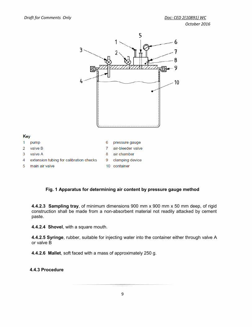
4.4 Pressure Gauge Method 4.4.1 Principle A known volume of air at a known pressure is merged in a sealed air chamber with the unknown volume of air in the concrete sample. The dial on the pressure gauge is calibrated in terms of percentage of air for the resultant pressure. 4.4.2 Apparatus Using the procedure given in Annex A , the apparatus shall be in calibration, at the time of the test. It is recommended that the apparatus be calibrated at a frequency dependent on the use but at least once per year.

Draft for Comments Only Doc: CED 2(10891) WC
October 2016
8
4.4.2.1 Pressure gauge method apparatus shall consists of the following items:
a) Container: a flanged cylindrical vessel, of steel or other hard metal,, not readily attacked by cement paste, having minimum capacity of at least 0.005 m3 (5 liters) and ratio of diameter to height of not less than 0.75 or more than 1.25. The outer rim and the interior surfaces of the vessel shall be machined to a smooth finish. The container shall be watertight. The container and the cover assembly shall be suitable for an operating pressure of approximately 0.2 MPa
NOTE: The capacity of 0.005 m3 for the container is usually recommended for msa upto 40 mm. Higher container sizes may be used for higher msa. That is, 0.01 m3 for 80 mm and 0.1 m3 for 150 mm.
b) Cover assembly, consisting of a flanged rigid cover, of steel or any other hard material not readily attacked by cement paste. The outer rim and lower surface of the flange as well as the interior surfaces shall be machined to a smooth finish. The cover shall have provision for being clamped to the container to make a pressure seal without entrapping air at the joint between flanges of the cover and the container.
c) Pressure gauge, fitted to cover the assembly, calibrated to indicate air content from 0 to
at least 8 percent and preferably 10 percent.
The scale of the gauge shall be graduated as follows:
not more than 0.1 percent for the range (0 to 3) percent
not more than 0.2 percent for the range (3 to 6) percent
not more than 0.5 percent or the range (6 to 10) percent
d) Air pump, a pressure pump which may be built into the cover.
4.4.2.2 Scoop, approximately 100 mm wide
Draft for Comments Only Doc: CED 2(10891) WC
October 2016
9
Fig. 1 Apparatus for determining air content by pressure gauge method
4.4.2.3 Sampling tray, of minimum dimensions 900 mm x 900 mm x 50 mm deep, of rigid construction shall be made from a non-absorbent material not readily attacked by cement paste.
4.4.2.4 Shovel, with a square mouth.
4.4.2.5 Syringe, rubber, suitable for injecting water into the container either through valve A or valve B
4.4.2.6 Mallet, soft faced with a mass of approximately 250 g.
4.4.3 Procedure

Draft for Comments Only Doc: CED 2(10891) WC
October 2016
10
Thoroughly clean the flanges of the container and cover assembly. Clamp the cover assembly in place and ensure that there is a good seal between the cover and the container. Close the main air valve and open valve A and valve B (see Fig 1). Using a rubber syringe, inject water through either valve A or valve B until the water emerges from the other valve. Lightly tap the apparatus with the mallet until all entrapped air is expelled. Ensure that the air bleeder valve on the air chamber is closed and pump air into the air chamber until the hand on the pressure gauge is on the initial pressure line. After allowing a few seconds for the compressed air to cool to the ambient temperature, stabilize the hand on the pressure gauge at the initial pressure line by further pumping in or bleeding off air as necessary. During this process lightly tap the gauge, close both valve A and valve B and then open main air valve. Tap the sides of the container sharply. Lightly tap the pressure gauge to stabilize it, then read and record the value indicated in the pressure gauge, which is apparent
percentage of air, C1. Open valves A and B in order to release the pressure before the cover
assembly is removed. 4.5 Water-column method 4.5.1 Principle
Water is introduced to a predetermined height above a sample of compacted concrete of known volume in a sealed container and a predetermined air pressure is applied over the water. The reduction in volume of the air in the concrete sample is measured by observing the amount by which the water level is lowered, the water column being calibrated in terms of percentage of air in the concrete sample.
4.5.2 Apparatus
4.5.2.1 General
The apparatus shall be in calibration at the time of the test, using the procedure in Annex B. If the apparatus has been moved to a location that differs in elevation by more than 200 m from the location at which it was last calibrated, it shall be recalibrated; see Annex B.
It is recommended that the apparatus be calibrated at a frequency dependent upon use, but
at least once per year.
4.5.2.2 Water-column method apparatus, which shall consist of the following items (see
Figure 2):
a) Container, a flanged cylindrical vessel, of steel or other hard metal, not readily attacked by cement paste, having a nominal capacity of at least 5 l and a ratio of diameter to height of not less than 0.75 nor more than 1.25. The outer rim and upper surface of the flange and the interior surfaces of the vessel shall be machined to a smooth finish. The container shall be watertight. The container and the cover assembly shall be suitable for an operating pressure of approximately 0.1 MPa and be sufficiently rigid to limit the pressure expansion constant,
that is, to not more than 0.1 % air content.

Draft for Comments Only Doc: CED 2(10891) WC
October 2016
11
b) Cover assembly, a flanged rigid conical cover, fitted with a standpipe. The cover shall be of steel or other hard metal not readily attacked by cement paste and
shall have interior surfaces inclined at not less than 10 from the surface of the flange. The outer rim and lower surface of the flange and the sloping interior face shall be machined to a smooth finish. The cover shall have provision for being clamped to the container to make a pressure seal without entrapping air at the joint between the flanges of the cover and the container. c) Standpipe, consisting of a graduated glass tube of uniform bore or a metal tube of uniform bore with a glass gauge attached.
The graduated scale shall indicate air content of 0 to at least 8 percent and preferably 10 percent. The scale shall be graduated with divisions every 0.1 percent air content, the divisions being not less than 2 mm apart.
NOTE -- A scale in which 25 mm represents 1 percent of air content is convenient.
d) Cover, the cover shall be fitted with a suitable device for venting of the air chamber, a non-return air-inlet valve and a small valve for bleeding off water. The applied pressure shall be indicated by a pressure gauge connected to the air chamber above the water column. The gauge shall be graduated with divisions every 0.005 MPa, the divisions being not less than 2 mm apart. The gauge shall have a full-scale reading of 0.2 MPa. e) Deflecting plate or spray tube, a thin non-corrodible disc of not less than 100 mm diameter to minimize disturbance of the concrete when water is added to the apparatus. Alternatively, a brass spray tube of appropriate diameter that may be an integral part of the cover assembly or provided separately may be used. The spray tube shall be constructed so that when water is added to the container, it is sprayed onto the walls of the cover in such a manner as to flow down the sides causing minimum disturbance to the concrete. f) Air (pressure) pump, with a lead facilitating connection to the non-return air-inlet valve on the cover assembly.
4.5.2.3 Scoop, approximately 100 mm wide.
4.5.2.4 Remixing tray, of rigid construction, made from a non-absorbent material not readily attacked by cement paste.
It shall be of appropriate dimensions such that the concrete can be thoroughly remixed using a square-mouthed shovel.
4.5.2.5 Shovel, with a square blade.

Draft for Comments Only Doc: CED 2(10891) WC
October 2016
12
4.5.2.6 Container, fitted with a spout, having a capacity of 2 l to 5 l, to fill the apparatus with water.
4.5.2.7 Mallet, soft-faced, with a mass of approximately 250 g. 4.5.3 Filling the container and compacting the concrete
Fill the container and compact the concrete as described in 4.3.
Key
1 non-return valve 7 concrete
2 air vent or valve 8 air pump
3 bleed valve 9 pressure-lowered level
4 mark
5 water h1 reading at pressure P
6 clamp h2 reading at zero pressure after the pressure has been released
h1 h2 C1 when the container holds concrete.
h1 h2 G (aggregate correction factor) when the container holds only aggregate and water.
C1 G Cc (air content of concrete).
Figure 2 — Water-column method apparatus 4.5.4 Procedure
Thoroughly clean the flanges of the container and cover assembly. In the absence of the spray tube, place the deflecting plate, centrally on the concrete and press it into contact. Clamp the cover assembly in place, and ensure that there is good pressure seal between the cover and the container. Fill the apparatus with water and tap lightly with the mallet to remove air adhering to the

Draft for Comments Only Doc: CED 2(10891) WC
October 2016
13
interior surfaces of the cover. Bring the level of water in the standpipe to zero by bleeding through the small valve with the air vent open. Close the air vent and apply the operating pressure, P, by means of the air pump. Record the reading on the gauge tube, h1, and release the pressure. Read the gauge tube again and if the reading h2 is 0.2 percent air content or less, record the value (h1 - h2) as the apparent air content, C1, to the nearest 0.1 percent air by volume. If h2 is greater than 0.2 percent air content, apply the operating pressure, P, again, giving a gauge tube reading h3 and a final reading h4 after release of the pressure. If (h4 - h2) is 0.1 percent air content or less, record the value (h3 - h4) as the apparent air content. If (h4 - h2) is greater than 0.1 percent air content, it is possible that leakage is occurring and the test shall be disregarded.
4.6 Calculations and expression of results 4.6.1 Air content of the sample tested
Calculate the air content, Cc, of the concrete in the container from following equation
Cc = C1 – G
where,
C1 is the apparent air content, expressed to the nearest 0.1% of the sample
tested, G is the aggregate correction factor, expressed to the nearest 0.1%. The aggregate correction factor shall be determined as describe in Annex C. Express the air content as a percentage to the nearest 0.1 percent 4.7 Test Report
The test report shall include the following:
a) Identification of the test sample; b) Location of performance of test; c) Time and date of performance of test; d) Temperature of the remixed sample (optional); e) Observations on condition of test sample (optional); f) Consistence of the concrete g) Method of compaction: for mechanical compaction, the duration, for hand compaction, the number of strokes; h) Identification of person carrying out the test or part of the test; i) Any deviation from standard test method; j) Declaration by the person carrying out the test that it was carried out in accordance with
this standard, except as noted in cl 5.6 h). k) Aggregate correction; (where appropriate) l) identification of test method and procedure used, i.e. pressure-gauge method or water-
column method; m) information relevant to the specific test, e.g altitude;

Draft for Comments Only Doc: CED 2(10891) WC
October 2016
14
n) measured apparent air content; and
o) calculated air content (Cc) of the concrete.

Draft for Comments Only Doc: CED 2(10891) WC
October 2016
15
Annex A
Calibration of Apparatus for Pressure Gauge Method A.1 The calibration test detailed shall be made as frequently as necessary to check the accuracy of the graduations indicating air content on the dial of the pressure gauge. Recalibration of the apparatus is not required with changes in elevation at which it is used or with changes in atmospheric pressure. A.2 Apparatus The apparatus for calibration shall be as follows: A. 2.1 Calibration cylinder: made of brass or other non-corrodible metal, which may be integral with the cover assembly. The calibration cylinder shall consist of cylindrical measure having an internal volume equal to approximately 3 to 6 percent of the volume of the measuring bowl.
A. 2.2 Transparent plate: It shall be rigid and transparent, suitable for use as a closure for the container. A.2.3 Balances: These shall be capable of weighing up to 1 kg to an accuracy of ± 0.5 g, over the range used in the test and upto 20 kg to an accuracy of ± 5 g over the range used in the test. A.3 Checking the capacity of the container The capacity of the container is found by determining the mass of water, mw,con , required to fill it. Smear a thin film of grease on the flange of the container to make a watertight joint between the transparent plate and the top of the container. Fill the container with water at ambient temperature and place the transparent plate over it to eliminate any convex meniscus. Wipe away surplus water and determine the mass of the container filled with water by weighing on the balance. A.4 Checking air content graduations on the pressure gauge Screw the extension tubing (see Fig. 1) into the threaded hole beneath valve A on the underside of the cover assembly and clamp the cover assembly into place, taking care to ensure that there is a good pressure seal between cover and container. Close main air valve and open valves A and B. Add water through valve A until all trapped air has been expelled through valve B. Pump air into the air chamber until the pressure reaches the indicated initial pressure line. After allowing a few seconds for the compressed air to cool to ambient temperature, stabilize the indicator on the pressure gauge at the initial pressure line by further pumping in or bleeding off air as necessary. During this process lightly tap the gauge and close valve B.
Draft for Comments Only Doc: CED 2(10891) WC
October 2016
16
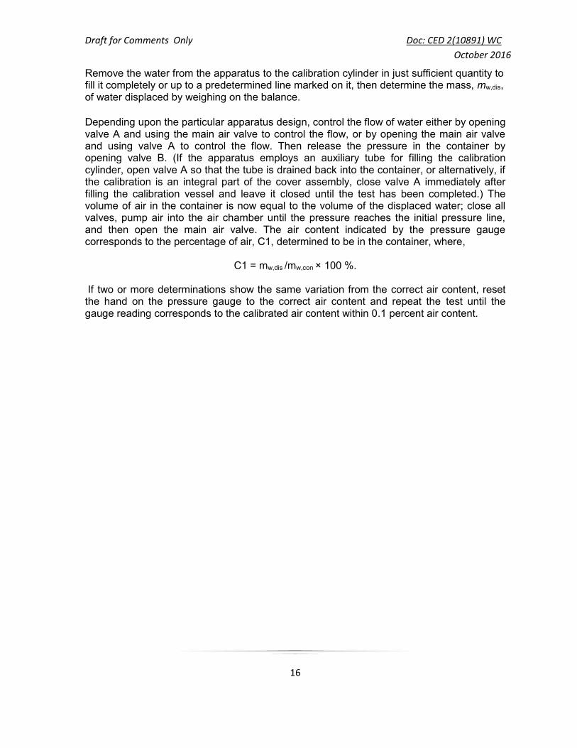
Remove the water from the apparatus to the calibration cylinder in just sufficient quantity to fill it completely or up to a predetermined line marked on it, then determine the mass, mw,dis, of water displaced by weighing on the balance. Depending upon the particular apparatus design, control the flow of water either by opening valve A and using the main air valve to control the flow, or by opening the main air valve and using valve A to control the flow. Then release the pressure in the container by opening valve B. (If the apparatus employs an auxiliary tube for filling the calibration cylinder, open valve A so that the tube is drained back into the container, or alternatively, if the calibration is an integral part of the cover assembly, close valve A immediately after filling the calibration vessel and leave it closed until the test has been completed.) The volume of air in the container is now equal to the volume of the displaced water; close all valves, pump air into the air chamber until the pressure reaches the initial pressure line, and then open the main air valve. The air content indicated by the pressure gauge corresponds to the percentage of air, C1, determined to be in the container, where,
C1 = mw,dis /mw,con × 100 %. If two or more determinations show the same variation from the correct air content, reset the hand on the pressure gauge to the correct air content and repeat the test until the gauge reading corresponds to the calibrated air content within 0.1 percent air content.

Draft for Comments Only Doc: CED 2(10891) WC
October 2016
17
Annex B
(normative) Calibration of apparatus — Water-column method
B.1 General The calibration tests described in B.3, B.4, B.5 and B.6 shall be made at the time of the initial calibration of the apparatus and at any time when it is necessary to check whether the capacity of the calibration cylinder or container may have changed. The calibration test described in B.7 and B.8 shall be made as frequently as necessary to check the pressure gauge in order to ensure that the proper gauge pressure, P, is being used. Recalibration of the apparatus shall also be required when the location at which it is to be used varies in elevation by more than 200 m from that at which it was last calibrated. B.2 Apparatus The apparatus shall be as follows: B.2.1 Calibration cylinder, hollow, made of brass or other strong non-corroding metal, having a capacity of approximately 0.3 l. The rim of the cylinder shall be machined to a smooth plane surface at right angles to the axis of the cylinder. B.2.2 Support, for the calibration cylinder, made of non-corroding material and which allows free flow of water into and out of the cylinder in the inverted position. B.2.3 Spring, non-corroding coil, spring or equivalent for retaining the calibration cylinder in place. B.2.4 Transparent plates, two, rigid, one suitable for use as a closure for the calibration cylinder and one as a closure for the container. B.2.5 Balances: These shall be capable of weighing up to 1 kg to an accuracy of ± 0.5 g, over the range used in the test and upto 20 kg to an accuracy of ± 5 g over the range used in the test. B.3 Capacity of the calibration cylinder Using the 1-kg balance, determine the capacity of the calibration cylinder by measuring the mass of water required to fill it. For this purpose, fill the weighed cylinder with water at ambient temperature (15°C to 25°C) and carefully cover it with the previously weighed transparent plate, ensuring that no air bubbles are trapped under the plate and that surplus water is wiped away before weighing the assembly. By repeating this procedure, make a total of three weighings of the covered cylinder filled with water. Calculate the average mass, mw,cyl, of water contained in the full cylinder and record it to the nearest 0.5 g. B.4 Capacity of the container

Draft for Comments Only Doc: CED 2(10891) WC
October 2016
18
Using the 20kg balance, determine the capacity of the container by measuring the mass of water required to fill it. For this purpose, smear a thin film of grease on the flange of the container, and, after weighing together with the transparent plate, fill with water at ambient temperature (15 °C to 25 °C) and make a watertight joint by sliding the transparent plate over the top of the container, ensuring that no air bubbles are trapped under the plate and that surplus water is wiped away before weighing the assembly. By repeating this procedure, make a total of three weighings of the covered container filled with water. Calculate the average mass, mw,con, of water contained in the full container and record it to the nearest 5 g. B.5 Pressure expansion constant The pressure expansion constant, e, is determined by filling the apparatus with water, making sure that all entrapped air has been removed and that the water level is exactly on the zero mark, and applying an air pressure of 100 kPa. The reading of water column (in percent air content) will be the pressure expansion constant, e, for the apparatus. Strictly speaking, the air pressure applied during this procedure should be the required operating pressure, P, determined as in B.7. However, as the value of e is needed to determine P by way of the calibration constant K, a logically closed cycle of operations exists. In practice, the change in e due to a change in P is small enough to be ignored. As P is commonly about 100 kPa, this value is prescribed to overcome the problem. Its use will lead to a value of e that is sufficiently accurate for the test. B.6 Calibration constant The calibration constant, K, is the reading needed on the air content scale during the routine calibration procedure to obtain the gauge pressure required to make the graduations on the air content scale correspond directly to the percentage of air introduced into the container by the calibration cylinder when the container is full of water. The constant, K, is generally calculated in accordance with Equation below:
K = 0.98 x R + e where
e is the pressure expansion constant (see B.5);
R is the capacity of the calibration cylinder expressed relative to the capacity of the container and is calculated as follows; see B.3 and B.4:
NOTE -- The factor 0.98 is used to correct for the reduction in the volume of air in the calibration vessel when it is compressed by a depth of water equal to the depth of the

Draft for Comments Only Doc: CED 2(10891) WC
October 2016
19
container. This factor is approximately 0.98 for a 200 mm deep container at sea level. Its value decreases to approximately 0,975 at 1 500 m above sea level and 0,970 at 4000 m above sea level. The value of the constant will decrease by about 0.01 for each 100 mm increase in bowl depth. Hence the term 0.98 x R represents the effective volume of the calibration vessel, expressed as a percentage of the container under normal operating conditions.
B.7 Required operating pressure Place the calibration cylinder support centrally on the bottom of the clean container and place the cylinder on the support with its open end downward. Place the coil spring on the cylinder and clamp the cover assembly carefully in place. Fill the apparatus with water at ambient temperature to a level above the zero mark on the air content scale. Close the air vent and pump air into the apparatus approximately to the operating pressure (about 100 kPa). Lightly tap the sides and cover with the mallet to remove as much entrapped air as possible adhering to the interior surfaces of the apparatus and gradually reduce the pressure by opening the vent. Bring the water level exactly to the zero mark by bleeding water through the small valve in the conical cover and close the air vent. Apply pressure by means of the pump until the reading of the water level equals the calibration constant, K (see B.6). Record the pressure, P, indicated on the pressure gauge. Gradually release the pressure by opening the vent until zero pressure is indicated. If the water level returns to a reading less than 0.05 percent air content, take the pressure, P, as the operating pressure. If the water level fails to return to a reading below 0.05 % air content, check the apparatus for leakage and repeat the procedure. B.8 Alternative operating pressure The range of air contents that can be measured with a particular apparatus can be extended by determining an appropriate alternative operating pressure. For example, if the range is to be doubled, the alternative operating pressure, P1, is that for which the apparatus indicates half of the calibration reading, K, (see B.6). Exact calibration requires the determination of the pressure expansion constant, e (see B.5), for the reduced operating pressure but, since the change in the pressure expansion constant can normally be disregarded, the alternative operating pressure can be determined during the determination of the normal operating pressure (see B.7).

Draft for Comments Only Doc: CED 2(10891) WC
October 2016
20
Annex C
Aggregate Correction Factor for Pressure Gauge Method C.1 General The aggregate correction factor will vary with different aggregates and although ordinarily it will remain reasonably constant for a particular aggregate, an occasional check should be carried out. The aggregate correction factor can be determined only by a test, as it is not directly related to the water absorption of the particles. C.2 Aggregate sample size Determine the aggregate correction factor by applying the operating pressure on a combined sample of the coarse and fine aggregates in the approximate amounts, proportions and moisture conditions that exist in the concrete sample. Obtain the sample of aggregate either by washing the cement through a 150 μm sieve from the concrete sample tested or by using a combined sample of fine and coarse aggregate similar to that used in
the concrete. In the latter case calculate the masses, mf and mc, of fine and coarse
aggregate, respectively, to be used from Equations below:
mf = Vo ρfr ff
mc = Vo ρfr fc where,
ff and fc : the proportions, expressed as fractions by mass of the total concrete
mix (aggregates, cement and water), of the fine and the coarse aggregate, respectively;
Vo is the capacity, expressed in m3, of the container determined as specified in A.3;
ρfr is the density, expressed in kg/m3, of concrete to be tested, determined in
accordance with IS 1199(Part 3) or calculated from the known proportions and densities of the materials and the nominal air content.
C.3 Filling the container Partially fill the container of the apparatus with water, then introduce the combined sample of aggregate in small scoopfuls. This shall be done in such a manner as to entrap as little air as possible. If necessary, add additional water to inundate all of the aggregate. After the addition of each scoopful, remove any foam promptly, then stir the aggregate with the compacting bar and tap the container with the mallet to release any entrapped air.

Draft for Comments Only Doc: CED 2(10891) WC
October 2016
21
C.4 Determination of aggregate correction factor When all the aggregate has been placed in the container, wipe clean the flanges of the container and the cover assembly thoroughly and clamp the cover assembly into position, so that a pressure -tight seal is obtained. Close the main valve and open valves A and B. Using the rubber syringe, inject water through either valve A or valve B until water emerges from the other valve. Tap the apparatus lightly with the mallet until all entrapped air is expelled from this same valve. Remove a volume of water from the container approximately equivalent to the volume of air that would be contained in a typical concrete sample of a size equal to the volume of the container. Remove the water in the apparatus in the manner described in A.4 for the calibration test. Complete the test using the procedure described in 4.4.3. The aggregate correction factor, G, expressed as a percentage of the capacity of the container, is equal to the reading on the air content scale minus the volume of water removed from the container.

Draft for Comments Only Doc: CED 2(10891) WC
October 2016
22
Annex D Aggregate Correction Factor for Water Column Method
D.1 General The aggregate correction factor will vary with different aggregates and, although it will remain reasonably constant for a particular aggregate, an occasional check should be carried out. The aggregate correction factor can be determined only by a test, as it is not directly related to the water absorption of the particles. D.2 Aggregate sample size Determine the aggregate correction factor by applying the operating pressure on a combined sample of the coarse and fine aggregates in the approximate amounts, proportions and moisture conditions that exist in the concrete sample. Obtain the sample of aggregate either by washing the cement through a 150 μm sieve from the concrete sample tested or by using a combined sample of fine and coarse aggregate similar to that used in
the concrete. In the latter case calculate the masses, mf and mc, of fine and coarse
aggregate, respectively, to be used from Equations below:
mf = Vo ρfr ff
mc = Vo ρfr fc where,
ff and fc : the proportions, expressed as fractions by mass of the total concrete
mix (aggregates, cement and water), of the fine and the coarse aggregate, respectively;
Vo is the capacity, expressed in m3, of the container determined as specified in A.3;
ρfr is the density, expressed in kg/m3, of concrete to be tested, determined in
accordance with IS 1199(Part 3) or calculated from the known proportions and densities of the materials and the nominal air content.
D.3 Filling the container Partially fill the container of the apparatus with water, then introduce the combined sample of aggregate in small scoopfuls. This shall be done in such a manner as to entrap as little air as possible. If necessary, add additional water to inundate all of the aggregate. After the addition of each scoopful, remove any foam promptly, then stir the aggregate with the compacting bar and tap the container with the mallet to release any entrapped air.

Draft for Comments Only Doc: CED 2(10891) WC
October 2016
23
D.4 Determination of aggregate correction factor When all the aggregate has been placed in the container, wipe clean the flanges on the container and clamp the cover in position. Fill the apparatus with water and tap lightly with the mallet to remove air adhering to the interior surfaces of the apparatus. Bring the level of the water in the standpipe to zero but bleeding through the small valve with the air vent open. Close the air vent and apply the operating pressure, P, by means of the air pump Record the reading of the gauge tube as h1, release the pressure and take a further reading, h2. Repeat the entire procedure once, obtaining a second pair of readings, h3 and h4. Take the average value of (h1-h2) and (h3-h4) as the aggregate correction factor, G, unless the two value of (h1-h2) and (h3-h4) differ by more than 0.1 percent air content, in which case carry out further determinations until consistent results are obtained.