manak bhavan, 9 bahadur shah zafar marg, …11290)_30012017.pdf · manak bhavan, 9 bahadur shah...
TRANSCRIPT

MANAK BHAVAN, 9 BAHADUR SHAH ZAFAR MARG, NEW DELHI 110002
हमारा सदंभर् : सीईडी 2:2/टी-23 25 01 2017
त कनीकी सिमित : सीमट और कंक्रीट िवषय सिमित, सीईडी 2 प्रा त कतार् : 1 िसिवल इंजीिनयरी िवभाग पिरष के िच रखने वाले सद य 2 सीईडी 2 के सभी सद य 3 िच रखने वाले अ य िनकाय
महोदय(य ),
िन निलिखत मानक के मसौदे सलंग्न ह:
प्रलेख सखं् या शीषर्क सीईडी CED 2 (11290)WC कंक्र�ट �मश्र अनुपातन – मागर्दश� िस धांत
(IS 10262 का दसूरा पुनरीक्षण) ICS No. 91.100.30
कृपया इस मानक के मसौदे का अवलोकन कर और अपनी स मितयॉ यह बताते हुए भेजे िक यिद ये मानक के प म प्रकािशत हो तो इन पर अमल करने म आपके यवसाय अथवा कारोबार म क् या किठनाइया आ सकती ह।
स मितया भेजने की अंितम ितिथ 25 माचर् 2017
स मित यिद कोई हो तो कृपया [email protected] या [email protected] पर ईमेल करे।
यिद कोई स मित प्रा त नहीं होती है अथवा स मित म केवल भाषा स ब धी त्रिुट हुई तो उपरोक् त प्रलेख को यथावत अंितम प िदया जाएगा । यिद सि म त तकनीकी प्रकृित की हुई तो िवषय सिमित के अ यक्ष के परामशर् से अथवा उनकी इ छा पर आगे की कायर्वाही के िलए िवषय सिमित को भेजे जाने के बाद प्रलेख को अिंतम प दे िदया जाएगा ।
यह प्रलेख भारतीय मानक यरूो की वैबसाइट www.bis.org.in पर भी है ।
ध यवाद । भवदीय,
(संजय पंत) संलग्न : उपिर लिखत प्रमुख (िसिवल इंजीिनयरी)
यापक पिरचालन मसौदा

MANAK BHAVAN, 9 BAHADUR SHAH ZAFAR MARG, NEW DELHI 110002
DOCUMENT DESPATCH ADVICE
TECHNICAL COMMITTEE: Cement and Concrete Sectional Committee, CED 2 ADDRESSED TO:
1. All Members of Civil Engineering Division Council, CEDC
2. All Members of CED 2,
3. All others interested
Dear Sir (s), Please find enclosed the following documents:
Doc No. Title
CED 2 (11290)WC GUIDELINES FOR CONCRETE MIX PROPORTIONING (Second Revision of IS 10262) ICS No. 91.100.30
Kindly examine the draft and forward your views stating any difficulties which you are likely
to experience in your business or profession, if this is finally adopted as National Standard. Last Date for comments: 25 March 2017. Comments if any, may please be made in the format as given overleaf and mailed to
[email protected] or [email protected]. In case no comments are received or comments received are of editorial nature, you will
kindly permit us to presume your approval for the above document as finalized. However, in case comments of technical in nature are received then it may be finalized either in consultation with the Chairman, Sectional Committee or referred to the Sectional Committee for further necessary action if so desired by the Chairman, Sectional Committee.
The documents are also hosted on BIS website www.bis.org.in. Thanking you,
Yours faithfully,
(Sanjay Pant) Encl: as above Head (Civil Engg.)
DRAFTS IN WIDE CIRCULATION
Reference Date
CED 2:2/T-23 25 01 2017

Draft for comments only CED 2(11290)WC
January 2017
1
BUREAU OF INDIAN STANDARDS
Cement and Concrete
Sectional Committee, CED 2
Last Date for Comments:
25 March 2017
[ICS 91.100.30] Draft Indian Standard
GUIDELINES FOR CONCRETE MIX PROPORTIONING
(Second Revision of IS 10262)
Cement and Concrete Sectional Committee, CED 02
FOREWORD
(Formal clauses of the standard to be added later)
This standard provides the guidelines for proportioning concrete mixes as per the requirements using the concrete making materials including other supplementary materials identified for this purpose.
This standard was first published in 1982, and subsequently revised in 2009. Changes in the first revision, the major changes had been the modification of the title; the applicability was restricted to ordinary and standard grades of concrete, the standard was aligned with IS 456:2000 'Plain and Reinforced Concrete -- Code of Practice (fourth revision); the requirements for selection of water cement ratio, water content and estimation of coarse aggregates content and fine aggregate content were reviewed and modified; an additional illustrative example of concrete mix design was added, etc.
In this second revision, the following major modifications have been made: a) The standard has been divided into five sections,, as follows:
1) Section 1: General
2) Section 2: Ordinary and Standard Grades of Concrete
3) Section 3: High Strength grades of Concrete
4) Section 4: Self Compacting Concrete
5) Section 5: Mass Concrete
b) Mix design procedure for high strength concrete for M65 or above (up to target strength of M100)
c) The initial data to be provided for mix proportioning has been made more encompassing, covering
the provisions of revised IS 383 : 2015 'Coarse and Fine Aggregates for Concrete', admixtures,
etc.
d) The target strength for mix proportioning formula has been refined to include a new factor based
on the grade of concrete. This has been done to ensure a minimum margin between the
characteristic compressive strength and the target mean compressive strength.
e) The calculations for standard deviation have been detailed.
f) A graph of water-cement ratio versus 28 day strength of concrete has been introduced for different
grades and types of cement, as an alternate method for assuming the initial water-cement ratio.

Draft for comments only CED 2(11290)WC
January 2017
2
j) Illustrative annexes for concrete mix proportioning using high strength concrete, self compacting
concrete and for mass concreting have been added.
k) Guidelines on using/selecting water reducing admixtures have been introduced as an informatory
Annex (see Annex F).
l) The consideration of air content in design of normal (non- air entrained) concrete mix proportion,
has been reintroduced.
Concrete has become an indispensable construction material. According to the present state-of-the-art, concrete has bypassed the stage of mere four component system, that is, cement, water, coarse aggregate and fine aggregate. It can be a combination of far more number of ingredients for example, a judicious combination of ingredients from as many as ten materials. In the recent past, apart from the four ingredients mentioned above, fly ash, ground granulated blast furnace slag, silica fume, rice husk ash, metakaoline and superplasticizer are six more ingredients which are generally used in concrete produced in practice as the situation demands. Hence, it is all the more essential at this juncture to have general guidelines on proportioning concrete mixes. The need has been further augmented by the importance given to proportioned concrete mixes according to IS 456 : 2000. The objective of proportioning concrete mixes is to arrive at the most economical and practical combinations of different ingredients to produce concrete that will satisfy the performance requirements under specified conditions of use. An integral part of concrete mix proportioning is the preparation of trial mixes and effect adjustments to such trials to strike a balance between the requirements of placement, that is, workability and strength, concomitantly satisfying durability requirements. Concrete has to be of satisfactory quality both in its fresh and hardened states. This task is best accomplished by trial mixes arrived at by the use of certain established relationships among different parameters and by analysis of data already generated thereby providing a basis for judicious combination of all the ingredients involved. The basic principles which underline the proportioning of mixes are Abram's law for strength development and Lyse's rule for making mix with adequate workability for placement in a dense state so as to enable the strength development as contemplated. From practical view point, compressive strength is often taken as an index of acceptability. This does not necessarily satisfy the requirements of durability unless examined under specific context. Mix proportioning is generally carried out for a particular compressive strength requirement ensuring that fresh concrete of the mix proportioned to possess adequate workability for placement without segregation and bleeding while attaining a dense state. In addition, the method has scope to consider the combination of wider spectrum of cement and mineral admixtures proposed to be used to meet the requirements of durability for the type of exposure conditions anticipated in service. Proportioning of concrete mixes can be regarded as procedure set to proportion the most economical concrete mix for specified durability and grade for required site conditions. As a guarantor of quality of concrete in the construction, the constructor should carry out mix proportioning and the engineer-in-charge should approve the mix so proportioned. The method given in this standard is to be regarded as the guidelines only to arrive at an acceptable product, which satisfies the requirements of placement required with development of strength with age and ensures the requirements of durability. This standard does not debar the adoption of any other established methods of concrete mix proportioning.

Draft for comments only CED 2(11290)WC
January 2017
3
For the purpose of deciding whether a particular requirement of this standard is complied with, the final value, observed or calculated, expressing the result of a test or analysis, shall be rounded of in accordance with IS 2 : 1960 'Rules for rounding off numerical values (revised)' .The number of significant places retained in the rounded off value should be the same as that of the specified value in this standard.
BUREAU OF INDIAN STANDARDS
Cement and Concrete
Sectional Committee, CED 2
Last Date for Comments:
25 March 2017
[ICS 91.100.30] Draft Indian Standard
GUIDELINES FOR CONCRETE MIX PROPORTIONING (Second Revision of IS 10262)
SECTION 1 GENERAL
1 SCOPE
1.1 This standard provides the guidelines for proportioning concrete mixes as per the requirements using the concrete making materials including other supplementary materials identified for this purpose. The proportioning is carried out to achieve specified characteristics at specified age, workability of fresh concrete and durability requirements.
1.2 This standard is applicable for ordinary, standard and high strength concrete grades. The standard also covers provisions for the mix proportioning of self compacting concrete and mass concrete.
1.3 All requirements of IS 456 in so far as they apply, shall be deemed to form part of this standard.
2 REFERENCES
The following standards contain provisions, which through reference in this text, constitute provisions of this standard. At the time of publication, the editions indicated were valid. All standards are subject to revision and parties to agreements based on this standard are encouraged to investigate the possibility of applying the most recent editions of the standards indicated below:
IS No. Title
269 : 2015 Specification for ordinary Portland cement (Sixth revision) 383: 2016 Specification for coarse and fine aggregates for concrete (second revision) 455: 2015 Specification for Portland slag cement (Fourth revision) 456: 2000 Code of practice for plain and reinforced concrete (fourth revision) 1199 (Part 6) :20xx Methods of test and analysis of fresh concrete Part 6 Tests on fresh self
compacting concrete (Under Preparation) 1489 (Part 1):2015 Specification for Portland-pozzolana cement Part 1 Fly ash based (Third revision)
Draft for comments only CED 2(11290)WC
January 2017
4
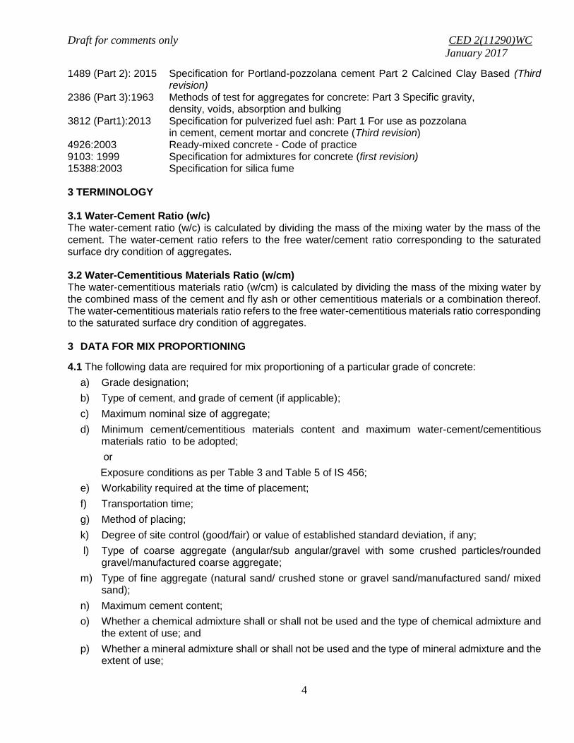
1489 (Part 2): 2015 Specification for Portland-pozzolana cement Part 2 Calcined Clay Based (Third revision)
2386 (Part 3):1963 Methods of test for aggregates for concrete: Part 3 Specific gravity, density, voids, absorption and bulking 3812 (Part1):2013 Specification for pulverized fuel ash: Part 1 For use as pozzolana
in cement, cement mortar and concrete (Third revision) 4926:2003 Ready-mixed concrete - Code of practice 9103: 1999 Specification for admixtures for concrete (first revision) 15388:2003 Specification for silica fume 3 TERMINOLOGY 3.1 Water-Cement Ratio (w/c) The water-cement ratio (w/c) is calculated by dividing the mass of the mixing water by the mass of the cement. The water-cement ratio refers to the free water/cement ratio corresponding to the saturated surface dry condition of aggregates. 3.2 Water-Cementitious Materials Ratio (w/cm) The water-cementitious materials ratio (w/cm) is calculated by dividing the mass of the mixing water by the combined mass of the cement and fly ash or other cementitious materials or a combination thereof. The water-cementitious materials ratio refers to the free water-cementitious materials ratio corresponding to the saturated surface dry condition of aggregates. 3 DATA FOR MIX PROPORTIONING
4.1 The following data are required for mix proportioning of a particular grade of concrete:
a) Grade designation;
b) Type of cement, and grade of cement (if applicable);
c) Maximum nominal size of aggregate;
d) Minimum cement/cementitious materials content and maximum water-cement/cementitious materials ratio to be adopted;
or
Exposure conditions as per Table 3 and Table 5 of IS 456;
e) Workability required at the time of placement;
f) Transportation time;
g) Method of placing;
k) Degree of site control (good/fair) or value of established standard deviation, if any;
l) Type of coarse aggregate (angular/sub angular/gravel with some crushed particles/rounded gravel/manufactured coarse aggregate;
m) Type of fine aggregate (natural sand/ crushed stone or gravel sand/manufactured sand/ mixed sand);
n) Maximum cement content;
o) Whether a chemical admixture shall or shall not be used and the type of chemical admixture and the extent of use; and
p) Whether a mineral admixture shall or shall not be used and the type of mineral admixture and the extent of use;
Draft for comments only CED 2(11290)WC
January 2017
5
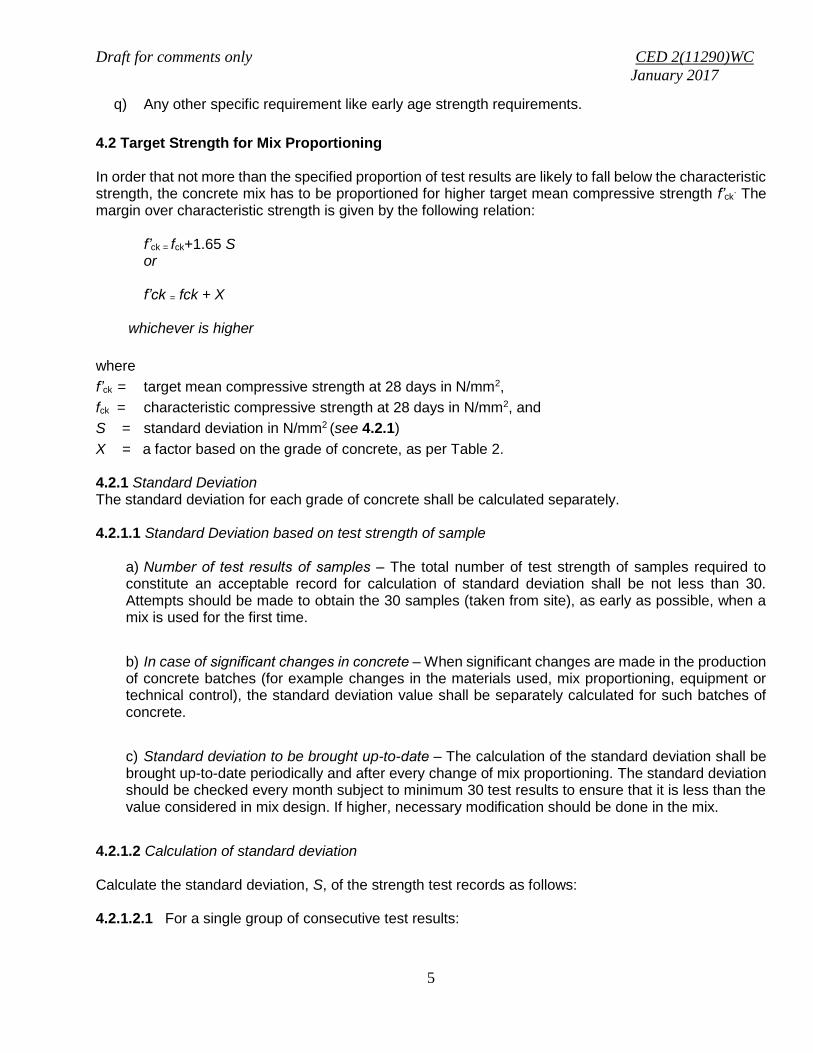
q) Any other specific requirement like early age strength requirements.
4.2 Target Strength for Mix Proportioning In order that not more than the specified proportion of test results are likely to fall below the characteristic strength, the concrete mix has to be proportioned for higher target mean compressive strength f’ck
. The margin over characteristic strength is given by the following relation:
f’ck = fck+1.65 S or f’ck = fck + X
whichever is higher
where
f’ck = target mean compressive strength at 28 days in N/mm2,
fck = characteristic compressive strength at 28 days in N/mm2, and
S = standard deviation in N/mm2 (see 4.2.1)
X = a factor based on the grade of concrete, as per Table 2. 4.2.1 Standard Deviation The standard deviation for each grade of concrete shall be calculated separately. 4.2.1.1 Standard Deviation based on test strength of sample
a) Number of test results of samples ‒ The total number of test strength of samples required to constitute an acceptable record for calculation of standard deviation shall be not less than 30. Attempts should be made to obtain the 30 samples (taken from site), as early as possible, when a mix is used for the first time.
b) In case of significant changes in concrete ‒ When significant changes are made in the production of concrete batches (for example changes in the materials used, mix proportioning, equipment or technical control), the standard deviation value shall be separately calculated for such batches of concrete.
c) Standard deviation to be brought up-to-date ‒ The calculation of the standard deviation shall be brought up-to-date periodically and after every change of mix proportioning. The standard deviation should be checked every month subject to minimum 30 test results to ensure that it is less than the value considered in mix design. If higher, necessary modification should be done in the mix.
4.2.1.2 Calculation of standard deviation Calculate the standard deviation, S, of the strength test records as follows: 4.2.1.2.1 For a single group of consecutive test results:

Draft for comments only CED 2(11290)WC
January 2017
6
)1(
)(1
2
n
XX
S
n
i
i
Where
S = standard deviation of the group
n = number of test results considered
X = average of n test results considered, and
Xi = individual test result
4.2.1.2.2 For two groups (mixes) of consecutive test results of same grade
)2(
)1()1(
21
2
22
2
11
nn
snsnS
Where
S = standard deviation for the two groups combined
S1, S2 = standard deviation for group 1 and 2, respectively, calculated as per 4.2.1.2.1
n1, n2 = number of test results in group 1 and 2, respectively, where both n1 and n2 shall not be less than 10, and n1+ n2 shall not be less than 30.
4.2.1.3 Assumed standard deviation
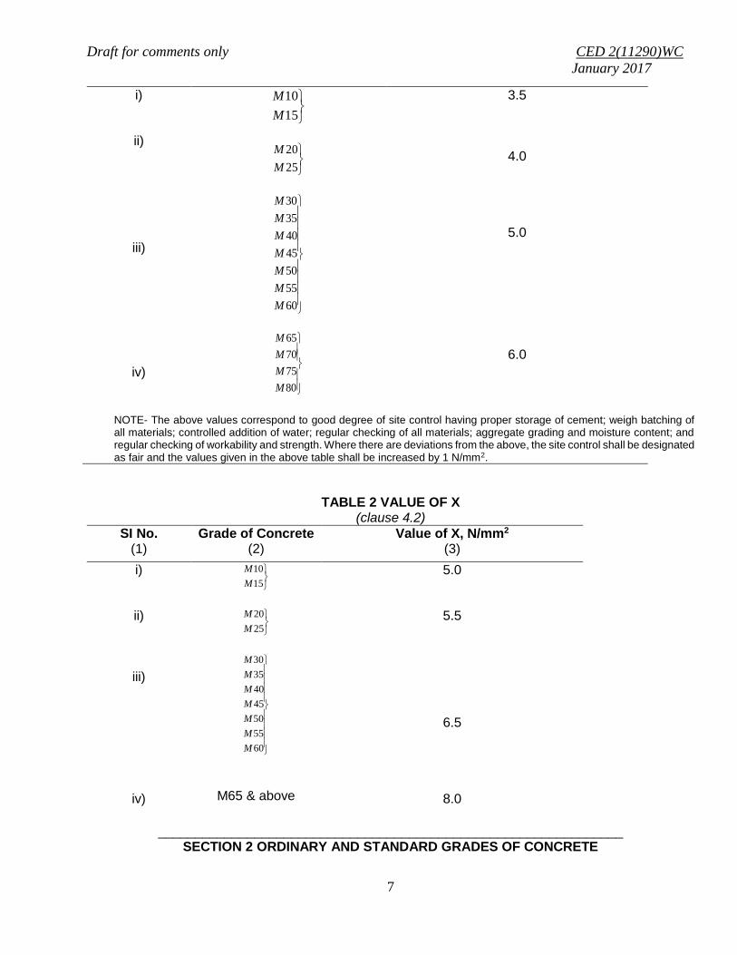
Where sufficient test results for a particular grade of concrete are not available, the value of standard deviation given in Table 1 may be assumed for the proportioning of mix in the first instance. As soon as the results of samples are available, actual calculated standard deviation shall be used and the mix may be proportioned suitably. However, when adequate past records for a similar grade exist and it is justified to adopt a value of standard deviation different from that shown in Table 1, it shall be permissible to use that value.
TABLE 1 ASSUMED STANDARD DEVIATION (clause 4.2.1.3)
SI No.
(1) Grade of Concrete
(2) Assumed Standard Deviation N/mm2
(3)
Draft for comments only CED 2(11290)WC
January 2017
7
i)
ii)
iii)
iv)
15
10
M
M
25
20
M
M
60
55
50
45
40
35
30
M
M
M
M
M
M
M
80
75
70
65
M
M
M
M
3.5
4.0
5.0
6.0
NOTE- The above values correspond to good degree of site control having proper storage of cement; weigh batching of all materials; controlled addition of water; regular checking of all materials; aggregate grading and moisture content; and regular checking of workability and strength. Where there are deviations from the above, the site control shall be designated as fair and the values given in the above table shall be increased by 1 N/mm2.
TABLE 2 VALUE OF X (clause 4.2)
SI No. (1)
Grade of Concrete (2)
Value of X, N/mm2 (3)
i)
ii)
iii)
iv)
15
10
M
M
25
20
M
M
60
55
50
45
40
35
30
M
M
M
M
M
M
M
M65 & above
5.0
5.5
6.5
8.0
_______________________________________________________________ SECTION 2 ORDINARY AND STANDARD GRADES OF CONCRETE

Draft for comments only CED 2(11290)WC
January 2017
8
5.0 SELECTION OF MIX PROPORTIONS 5.1 Selection of Water-Cement Ratio Different cements, supplementary cementitious materials and aggregates of different maximum size, grading, surface texture, shape and other characteristics may produce concrete of different compressive strength for the same free water-cement ratio. Therefore, the relationship between strength and free water-cement ratio should preferably be established for the materials actually to be used. In the absence of such data, the preliminary free water-cement ratio (by mass) corresponding to the target strength at 28 days may be selected from the relationship shown in Fig.1, for the respective grade of cement. In case, the actual strength of cement (OPC) is known, the curve corresponding to the actual strength of cement may be used.
Fig 1. Relationship between free water cement ratio and target concrete strength for different
grades of Cement

Draft for comments only CED 2(11290)WC
January 2017
9
NOTE ‒ While using PPC or PSC, the curve for 43 grade OPC can be utilized. Where the 28 day strength of PPC/PSC is known, appropriate curve corresponding to the 28 day compressive strength of cement shall be used for selection of water-cement ratio.
5.1.1 The water-cement ratio selected according to 5.1 should be checked against the limiting water-cement ratio for the requirements of durability and the lower of the two values adopted.
NOTE ‒ In case of water cement ratios on the upper limits of durability clause it is required that the water content contributed by the admixtures should also be considered in the calculations and the final water cement ratio should be fixed accordingly.
5.1.2 Where supplementary cementitious materials are used, that is, mineral admixtures, the water cementitious materials ratio shall be calculated, in accordance with Table 5 of IS 456 and this w/cm shall be in accordance with Table 4 and Table 5 of IS 456 or as specified.
5.2 Estimation of Air Content
Approximate amount of entrapped air to be expected in normal (non-air-entrained) concrete is given in Table 3.
TABLE 3 APPROXIMATE AIR CONTENT (clause 5.2)
Sl No Nominal Maximum Size
of Aggregate, mm Entrapped Air, as Percentage
of Volume of Concrete
i) ii) iii)
10 20 40
1.5 1.0 0.8
5.2.1 The actual values of air content can also be adopted during mix proportioning if; the site data (at least 5 results) for similar mix is available.
5.3 Selection of Water content and Admixture Content The water content of concrete is influenced by a number of factors, such as aggregate size, aggregate shape, aggregate texture, workability, water-cement ratio, cement and other supplementary cementitious materials type and content, chemical admixture and environmental conditions. An increase in aggregates size, a reduction in water-cement ratio and slumps, and use of rounded aggregate and water reducing admixture will reduce the water demand. On the other hand increased temperature, cement content, slump, water-cement ratio, aggregate angularity and a decrease in the proportion of the coarse aggregate to fine aggregate will increase water demand. The quantity of mixing water per unit volume of concrete may be determined from Table 4. The water content in Table 4 is for angular coarse aggregate and for 50 mm slump. The water estimate in Table 4 can be reduced by approximately 10 kg for sub-angular aggregates, 15 kg for gravel with some crushed particles and 20 kg for rounded gravel to produce same workability. For the desired workability (other than 50mm slump), the required water content may be increased or decreased by about 3 percent for each increase or decrease of 25 mm slump or may be established by trial. This illustrates the need for trial batch testing of the given materials as each aggregate source is different and can influence concrete properties. The water so calculated can be reduced by use of chemical admixture conforming to IS 9103. Water reducing admixture or super plasticizing admixtures usually decrease water content by 5 to 10 percent and 20 to 30 percent and above respectively at appropriate dosages.

Draft for comments only CED 2(11290)WC
January 2017
10
The requirement of water content and/or chemical admixture content may increase with the addition of high dosages of mineral admixture. The guidelines on selecting appropriate water reducing admixture and its dosages are given in Annex F.
Table 4 Water Content per Cubic Metre of Concrete for Nominal Maximum Size of Aggregate (clause 5.3)
Sl No. Nominal Maximum Size of Aggregate (mm)
Water Content1 (kg)
i) ii) iii)
10 20 40
208 186 165
1Water content corresponding to saturated surface dry aggregate. NOTES ‒ 1 These quantities of mixing water are for use in computing cement/cementitious materials content for trial batches. 2 On account of long distances over which concrete needs to be carried from batching plant/RMC plant, the concrete mix is generally designed for a higher slump initially than the slump required at the time of placing. The initial slump value shall depend on the distance of transport and loss of slump with time.
5.4 Calculation of Cement/Cementitious Materials Content The cement and supplementary cementitious materials content per unit volume of concrete may be calculated from the free water-cement ratio (see 5.1) and the quantity of water per unit volume of concrete. In certain situations, while using part replacement of cement by fly ash, ground granulated blast furnace slag (GGBS), silica fume, etc, increase in cementitious materials content may be warranted, particularly if fly ash is 20 percent or more and GGBS is 30 percent or more. The decision on increase in cementitious materials content and its percentage may be based on experience and trials; or the cementitious materials content so calculated may be increased by 10 percent for preliminary trial. The water-cementitious materials ratio may be recalculated, based on the increased cementitious materials content, as per Table 5 of IS 456. The cementitious materials content so calculated shall be checked against the minimum content for the requirements of durability as per IS 456 or as specified and greater of the two values adopted. The maximum cement content shall be in accordance with IS 456 or as specified. 5.4.1 The percentage of fly ash/GGBS to be used has to be decided based on the project requirement and the quality of these materials. 5.5 Estimation of Coarse Aggregate Proportion Aggregates of essentially the same nominal maximum size, type and grading will produce concrete of satisfactory workability when a given volume of coarse aggregate per unit volume of total aggregate is used. Approximate values for this aggregate volume are given in Table 5 for a water-cement/water-cementitious materials ratio of 0.5, which may be suitably adjusted for other water-cement ratios, the proportion of volume of coarse aggregates to that of total aggregates is increased at the rate of 0.01 for every decrease in water-cement ratio by 0.05 and decreased at the rate of 0.01 for every increase in water-cement ratio by 0.05.

Draft for comments only CED 2(11290)WC
January 2017
11
It can be seen that for equal workability, the volume of coarse aggregate in a unit volume of concrete is dependent only on its nominal maximum size and grading zone of fine aggregate. Differences in the amount of mortar required for workability with different aggregates, due to differences in particle shape and grading, can be adjusted by changing coarse to fine aggregate ratio. Generally higher fine aggregate content is required for crushed angular coarse aggregates due to increased surface area. 5.5.1 For more workable concrete mixes which is sometimes required when placement is by pump or when the concrete is required to be worked around congested reinforcing steel, it may be desirable to reduce the estimated coarse aggregate content determined using Table 5 up to 10 percent. However, caution shall be exercised to assure that the resulting slump, water-cement/cementitious materials ratio and strength properties of concrete are consistent with the recommendations of IS 456 and meet project specification requirements as applicable. Table 5 Volume of Coarse Aggregate per Unit Volume of Total Aggregate for Different Zones of
Fine Aggregate for Water-Cement/Water-Cementitious Materials Ratio of 0.50 (clause 5.5 and 5.5.1)
Sl. No.
(1)
Nominal Maximum Size of Aggregate,
mm (2)
Volume of Coarse Aggregate per Unit Volume of total Aggregate for Different Zones of Fine Aggregate
Zone IV
(3)
Zone III
(4)
Zone II
(5)
Zone I
(6)
1 10 0.54 0.52 0.50 0.48 2 20 0.66 0.64 0.62 0.60 3 40 0.73 0.72 0.71 0.69
NOTES 1 Volumes are based on aggregates in saturated surface dry condition.
2 These volumes are for Crushed (angular) aggregate and suitable adjustments may be made for other shape of aggregate.
3 Suitable adjustments may also be made for fine aggregate from other than natural sources, normally, crushed sand or
mixed sand may need lesser fine aggregate content. In that case, the coarse aggregate volume should be suitably increased.
5.6 Combination of Different Coarse Aggregate Fractions The coarse aggregate used shall conform to IS 383. Coarse aggregates of different sizes may be combined in suitable proportions so as to result in an overall grading conforming to Table 7 of IS 383 for particular nominal maximum size of aggregate. 5.7 Estimation of Fine and Coarse Aggregate Contents With the completion of procedure given in 5.4, all the ingredients have been estimated except the coarse and fine aggregate content. These quantities are determined by finding out the absolute volume of cementitious materials, water and the chemical admixture; by dividing their mass by their respective specific gravity, multiplying by 1/1000 and subtracting the result of their summation from unit volume. The values so obtained are divided into coarse and fine aggregate fractions by volume in accordance with coarse aggregate proportion already determined in 5.5. The coarse and fine aggregate contents are then determined by multiplying with their respective specific gravities and multiplying by 1000.

Draft for comments only CED 2(11290)WC
January 2017
12
5.8 Trial Mixes The calculated mix proportions shall be checked by means of trial batches. Workability of the trial mix No. 1 shall be measured. The mix shall be carefully observed for freedom from segregation and bleeding and its finishing properties. If the measured workability of Trial Mix No. 1 is different from the stipulated value, the water and/or admixture content shall be adjusted suitably. With this adjustment, the mix proportion shall be recalculated keeping the free water-cement ratio at the pre-selected value, which will comprise Trial Mix No. 2. In additional two more Trial Mixes No. 3 and 4 shall be made with the water content same as Trial mix No. 2 and varying the free water-cement/cementitious materials ratio by about ±10 percent of the preselected value, while satisfying the workability requirements as well. Mix No. 2 to 4 normally provides sufficient information, including the relationship between compressive strength and water-cement ratio, from which the mix proportions can be finalized, such that the strength and durability requirements are also satisfied. Additional field trials are recommended particularly for workability requirements. The concrete for field trials shall be produced by methods of actual concrete production. 5.9 Illustrative Examples An illustrative example of concrete mix proportioning is given in Annex A. Another illustrative example of mix proportioning of concrete using fly ash is given in Annex B. These examples are merely illustrative to explain the procedure and the actual mix proportioning shall be based on trial batches with the given materials.
SECTION 3 HIGH STRENGTH GRADES OF CONCRETE
6 HIGH STRENGTH CONCRETE (GRADE M65 & ABOVE)
High Strength Concrete is defined as the concrete that has characteristic compressive strength of 65 N/mm2 or more. This section provides the guidance for selecting mix proportion for M65 or above. Usually, for high strength concrete mixes specially selected cementitious materials and chemical admixtures i.e. super plasticizers are used, and achieving a low water – cementitious materials ratio (w/cm) is considered essential. The procedure for proportioning high strength concrete is similar to that required for ordinary/standard strength concrete. The procedure consists of series of steps that, when completed, provide a mixture meeting workability, strength and durability requirements based on the combined properties of the individually selected and proportioned ingredients. 6.1 Materials Materials shall be selected, proportioned and controlled carefully to achieve effective production of high strength concrete. To achieve high strength concrete optimum proportions should be selected, considering the cement and other cementitious materials properties, aggregate quality, aggregate gradation, paste volume, admixture type and dosage and mixing.

Draft for comments only CED 2(11290)WC
January 2017
13
6.1.1 Cementitious Materials
Proper selection of type of cement is very important step for the production of high strength concrete. Fly ash, silica fume, ground granulated blast furnace slag (GGBS) or metakaoline are widely used as a cementitious and pozzolanic ingredient in high strength concrete. Most high strength concrete mixture contains one or more supplementary cementitious materials such as fly ash, GGBS, silica fume or metakaoline.
6.1.2 Coarse Aggregate
In the proportioning of high strength concrete, the aggregates require special consideration and they greatly influence the strength and other properties of concrete. Therefore, the coarse aggregate should be strong, sufficiently sound, free of fissures or weak planes, clean and free of surface coating and shall meet the requirement of IS 383. Generally crushed stone aggregates with impact/crushing value not greater than 22 percent and combined flakiness and elongation index not more than 30 percent have been found suitable for high strength concrete.
6.1.3 Fine Aggregate The fine aggregates shall meet the requirements of IS 383. Generally, for high strength, a fine aggregate of coarser size is preferred (Zone I or Zone II), due to availability of high fines content from the cementitious materials.
6.1.4 Chemical Admixtures
High Strength Concrete mixes generally have a low water-cementitious materials ratio (w/cm). These low w/cm ratios are only attainable with High-range water-reducing admixtures (HRWRA). PC type (Poly carboxylate ether based) super plasticisers which reduce water content by 30 percent or above at appropriate dosages, shall be used.
6.2 Concrete Mix Proportioning
6.2.1 Target Strength for Mix Proportioning See 4.2
6.2.2 Selection of Maximum Size of Aggregate
Based on the strength requirement, the maximum size of aggregates is generally restricted to 20 mm; however, for grades M80 and above, aggregates of maximum size 10.0 to 12.5 may be preferable.
6.2.3 Estimation of Air Content
Approximate amount of entrapped air to be expected in normal (non-air-entrained) concrete is given in Table 6.
TABLE 6 APPROXIMATE AIR CONTENT (clause 6.2.3)
Nominal Maximum Size
of Aggregate, mm Entrapped Air, as Percentage
of Volume of Concrete
10.0 12.5 20.0
1.0 0.8 0.5

Draft for comments only CED 2(11290)WC
January 2017
14
6.2.3.1 The actual values of air content can also be adopted during mix proportioning if; the site data (at least 5 results) for similar mix is available.
6.2.4 Selection of Water content and Admixture Content
The quantity of water required to produce a given workability is influenced by many factors, including the
maximum size, particle shape and grading of the aggregate. The demand of water content is also influenced by the quantity of cement, pozzolanic material and the type of chemical admixture used. PCE type (Poly carboxylate ether based) super plasticisers which reduce water content by 30 percent or above at appropriate dosages, shall be used.
However, trial batching is the most effective way to determine the best proportions for the ingredients to be used. Table 7 gives estimates of water content for high strength concrete without chemical admixtures. The given water content is for 50 mm slump. For the desired workability (other than 50 mm slump), the required water content may be increased or decreased by about 3 percent for each increase or decrease of 25 mm slump or may be established by trial. These quantities of mixing water are maximum for well shaped, clean, angular and well graded coarse aggregates. Since the particle shape and surface texture of fine aggregate can significantly influence the mixing water demand, the water requirement may be different from the values given in Table 7 and shall be established by trials. The water so calculated shall be reduced by use of high range water reducing admixtures conforming to IS 9103.
The requirement of water content and/or chemical admixture content may increase with the addition of high dosages of mineral admixture. The guidelines on selecting appropriate water reducing admixture and its dosages are given in Annex F
NOTE ‒NOTE In case of water cement ratios on the upper limits of durability clause it is required that the water content contributed by the admixtures should also be considered in the calculations and the final water cement ratio should be fixed accordingly.
Table 7 Water Content per Cubic Metre of Concrete for Nominal Maximum Sizes of Aggregate (clause 6.2.4)
Sl No. Nominal Maximum Size of Aggregate (mm)
Maximum Water Content kg/m3
1 10.0 200
2 12.5 195 3 20.0 186
NOTES 1 Water content corresponding to saturated surface dry aggregate. 2 These quantities of mixing water are for use in computing cement/cementitious material content for trial batches. 3 On account of long distances over which concrete needs to be carried from batching plant/RMC plant, the concrete mix is generally designed for a higher slump initially than the slump required at the time of placing. The initial slump value shall depend on the distance of transport and loss of slump with time. Accordingly the adjustment for water content/admixture
dosage shall be made for the higher initial slump value.
6.2.5 Selection of Water – Cement Ratio (w/c): Table 8 gives the recommended values for w/c for high strength concrete made with silica fume and HRWRA as a function of maximum-size aggregates to achieve different target compressive strength at 28 days. In case, other cementitious materials such as fly ash are also used, the cementitious material

Draft for comments only CED 2(11290)WC
January 2017
15
content shall be suitably increased and the water cementitious material ratio shall be recalculated based on the total cementitious material used.
Table 8 Recommended w/cm for High Strength Concrete made with HRWRA.
(clause 6.2.5)
Target Compressive Strength at 28 days, N/mm2
w/c
Nominal Maximum Size of Aggregate, mm
10.0 mm 12.5 mm 20.0 mm
70 0.36 0.35 0.33
75 0.34 0.33 0.31
80 0.32 0.31 0.29
85 0.30 0.29 0.27
90 0.28 0.27 0.26
100 0.26 0.25 0.24
NOTE -- The recommended w/c are for a 28th day cement strength 53 MPa and above, for cement of other strength
values, suitable adjustments may be made.
6.2.6 Calculation of Cementitious Material Content
The cement and supplementary cementitious material content per unit volume of concrete may be calculated from the quantity of water (See 6.2.4) and the free water-cementitious materials ratio (See 6.2.5) per unit volume of concrete. However, this must satisfy the specification of maximum or minimum limit on the amount of cementitious material as per IS 456. If cement content (not including any mineral admixtures) more than the maximum cement content as given in IS 456 is to be used, it shall be ensured that the special consideration has been given in design to the increased risk of cracking due to drying shrinkage, or to early thermal cracking and to the increased risk of damage due to alkali silica reaction. The recommended dosages of different pozzolanic materials for high strength mixes are given in Table 9.
Table 9 (clause 6.2.6)
Pozzolanic Material (1)
Recommended dosages, percentage by mass of total
cementitious materials (2)
Fly ash 15 - 30 Ground Granulated Blast Furnace Slag 25 - 50
Silica Fume 5 - 10
6.2.7 Estimation of Coarse Aggregate Proportion The optimum content of the coarse aggregate depends on its strength and maximum nominal size of coarse aggregate. For proportioning of ordinary and standard grades of concrete, the optimum volume

Draft for comments only CED 2(11290)WC
January 2017
16
of coarse aggregate is given as a function of the maximum size of coarse aggregate and grading zone of fine aggregate. However, high strength grades of concrete are not dependent on the fine aggregate to provide fines for lubrication and consolidation of the fresh concrete as the mixes have high content of cementitious material. The recommended coarse aggregate volume per unit volume of total aggregate for different zones of fine aggregate is given in Table 10. For more workable concrete mixes which is sometimes required when placement is by pump or when the concrete is required to be worked around congested reinforcing steel, it may be desirable to reduce the estimated coarse aggregate content determined using Table10 up to 5 percent. However, caution shall be exercised to assure that the resulting slump, water-cement ratio and strength properties of concrete are consistent with the recommendations of IS 456 and meet project specification requirements as applicable Table 10: Volume of Coarse Aggregate per Unit Volume of Total Aggregate for Different Zones of Fine Aggregate for Water-Cement/Water-Cementitious Material Ratio of 0.30
(clause 6.2.7)
Sl. No.
(1)
Nominal Maximum Size of Aggregate,
mm (2)
Volume of Coarse Aggregate per Unit Volume of total Aggregate for Different Zones of Fine Aggregate
Zone III (3)
Zone II (4)
Zone I (5)
1 10.0 0.56 0.54 0.52
2 12.5 0.58 0.56 0.54 3 20.0 0.68 0.66 0.64
NOTES ‒
1 Volumes are based on aggregates in saturated surface dry condition.
2 These volumes are for Crushed (angular) aggregate and suitable adjustments may be made for other shape of aggregate.
3 Suitable adjustments may also be made for fine aggregate from other than natural sources, normally, crushed sand or mixed sand may need lesser fine aggregate content. In that case, the coarse aggregate volume should be suitably increased.
6.2.8 Estimation of Fine and Coarse Aggregate Contents With the completion of procedure given in 6.2.4, 6.2.5 and 6.2.6, all the ingredients would have been estimated except the coarse and fine aggregate content. These quantities are determined by finding out the absolute volume of cementitious material, water and the chemical admixture; by dividing their mass by their respective specific gravity, multiplying by 1/1000 and subtracting the result of their summation from unit volume. The values so obtained are divided into coarse and fine aggregate fractions by volume in accordance with coarse aggregate proportion already determined in 6.2.7. The coarse and fine aggregate contents are then determined by multiplying with their respective specific gravities and multiplying by 1000.
6.2.9 Trial Mixes The calculated mix proportions shall be checked by means of trial batches. Workability of the trial mix No. 1 shall be measured. The mix shall be carefully observed for freedom from segregation and bleeding and its finishing properties. It the measured workability of Trial Mix No. 1 is different from the stipulated value, the water and/or admixture content shall be adjusted suitably. With

Draft for comments only CED 2(11290)WC
January 2017
17
this adjustment, the mix proportion shall be recalculated keeping the free water-cement ratio at the pre-selected value, which will comprise Trial Mix No. 2. In additional two more Trial Mixes No. 3 and 4 shall be made with the water content same as Trial mix No. 2 and varying the free water-cement/cementitious materials ratio by ± 10 percent of the preselected value, while satisfying the workability requirements as well. . Mix No. 2 to 4 normally provides sufficient information, including the relationship between compressive strength and water-cementitious materials ratio, from which the mix proportions can be finalized. Additional field trials are recommended particularly for workability requirements. The concrete for field trials shall be produced by methods of actual concrete production. 6.4 Illustrative Examples An illustrative example of concrete mix proportioning for high strength concrete is given in Annex C. These examples are merely illustrative to explain the procedure and the actual mix proportioning shall be based on trial batches with the given materials.
SECTION 4 SELF COMPACTING CONCRETE
7.0 General Self compacting concrete (SCC) is highly flowable, non segregating concrete that fills uniformly and completely every corner of formwork by its own weight and encapsulate reinforcement without any vibration, whilst maintaining homogeneity. 7.1 Application Area Self compacting concrete (SCC) may be used in precast concrete applications or for concrete placed on site. SCC is used to cast sections with highly congested reinforcement and areas that present restricted access to placement and consolidation, including the construction of tunnel lining sections and the casting of hybrid concrete-filled steel tubular columns. It may be manufactured in a site batching plant or in a ready-mixed concrete plant and delivered to site by truck mixer. It may be placed either by pumping or pouring into horizontal or vertical forms. 7.2 Features of fresh Self Compacting Concrete A concrete mix can only be classified as Self-Compacting Concrete if the requirements for all below mentioned characteristic are fulfilled: a) Filling ability (Flowability), b) Passing ability, c) Segregation resistance, and d) Viscosity The above tests shall be carried out as per IS 1199 (Part 6). 7.2.1 Filling Ability (flowability) This is the ability of fresh concrete to flow into and fill all spaces within the formwork, under its own weight. Slump-flow test is performed to test the flowability. Slump-flow value describes the flowablity of a fresh mix in unconfined condition. Visual observation during the test can be additional information on the segregation resistance and uniformity.
Draft for comments only CED 2(11290)WC
January 2017
18
The following are typical slump-flow classes for a range of applications: SF1 (slump flow 550 mm - 650 mm) This class of SCC is appropriate for: a) Unreinforced or slightly reinforced concrete structures that are cast from the top with free displacement from the delivery point (for example, housing slabs) b) Casting by a pump injection system (for example, tunnel linings) c) Sections that are small enough to prevent long horizontal flow (for example, piles and some deep foundations). SF2 (slump flow 660 mm - 750 mm) is suitable for normal applications (for example, walls, columns) SF3 (slump flow 760 mm – 850 mm) is used for vertical applications in very congested structures, structures with complex shapes, or for filling under formwork. SF3 will often give better surface finish than SF 2 for normal vertical applications but segregation resistance is more difficult to control. 7.2.2 Passing Ability (free from blocking at reinforcement) Passing ability describe the capacity of the fresh mix to flow through confined spaces and narrow openings such as areas of congested reinforcement without segregation. If there is little or no reinforcement, there may be no need to specify passing ability as a requirement. L-box test is performed to check the passing ability. The minimum ratio of the height in the horizontal section relative to the vertical section is considered to be 0.8. If the SCC flows as freely as water, it will be completely horizontal, and the ratio will be equal to 1.0. 7.2.3 Segregation Resistance (Stability) The ability of fresh concrete to remain homogeneous in composition while in its fresh state. Segregation resistance (sieve) test is performed to check this property of fresh concrete.
After sampling, the fresh concrete is allowed to stand for 15 min and any separation of bleed water is noted. The top part of the sample is then poured into a sieve with 4.75 mm square apertures. After 2 minute, the weight of material which has passes through the sieve is recorded. The segregation ratio (SR) is then calculated as the proportion of the sample passing through the sieve. There are two classes of segregation resistance, namely SR1 & SR2. SR1 is generally applicable for thin slabs and for vertical applications with a flow distance of less than 5 m and a confinement gap greater than 80 mm. SR2 is preferred in vertical applications if the flow distance is more than 5 m with a confinement gap greater than 80 mm in order to take care of segregation during flow. Segregation resistance becomes an important parameter with higher slump-flow classes and/or the lower viscosity class, or if placing conditions promotes segregation. If none of these apply, it is usually not necessary to specify a segregation resistance class. For SR1 class segregation resistance should be 15 to 20 percent and for SR2 it should be less than 15 percent.
7.2.4 Viscosity Viscosity can be assessed by the V-funnel flow time as per IS 1199 (Part 6). Concrete with a low viscosity will have a very quick initial flow and then stop. Concrete with a high viscosity may continue to creep forward over an extended time.

Draft for comments only CED 2(11290)WC
January 2017
19
A V-shaped funnel is filled with fresh concrete and the time taken for the concrete to flow out of the funnel is measured and recorded as the V-funnel flow time. The viscosity is divided into two classes, that is, V1 & V2. V1 has good filling ability even with congested reinforcement. It is capable of self-leveling and generally has the best surface finish. V2 class viscosity is more likely to exhibit thixotropic effects, which may be helpful in limiting the formwork pressure or improving segregation resistance. But it may cause negative effects on surface finish and sensitivity to stoppages or delays between successive lifts. For V1 class, the time taken to pass the concrete from V-funnel should be ≤ 8 s and for V2 class the time taken to pass the concrete from V-funnel should be between 9 s to 25 s. 8.0 Mix Proportioning: 8.1 Mix Proportioning Principles a) Lower coarse aggregate content b) Increased paste content c) Low water/powder ratio (See NOTE) d) Increased superplasticiser e) Sometimes a viscosity modifying admixture.
NOTE ‒ Powder is the material of particle size smaller than 0.125 mm. It includes this size fraction in the cement, mineral
admixtures and aggregate. Water/powder ratio shall be 0.85 to 1.10 by volume.
8.2 Mix Proportioning approach
Laboratory trials should be used to verify properties of the initial mix composition with respect to the specified characteristics and classes. If necessary, adjustments to the mix composition should then be made. Once all requirements are fulfilled, the mix should be tested at full scale in the concrete plant and if necessary at site to verify both the fresh and hardened properties. The mix design is generally based on the approach outlined below:
a) Determine the target average compressive strength. b) Select the air content based on the specified nominal maximum size of aggregate. c) Select water-cement/cementitious materials ratio. d) Select the proportions for initial mix e) Select water content and cement/fly ash (or other supplementary cementitious material) content. f) Select admixture content. g) Select powder content and fine aggregate content. h) Select coarse aggregate content. j) Calculate volume of powder content and determine water powder ratio by volume, and make
adjustments if required. k) Work out the mix proportions for trial 1. m) Produce the fresh SCC in the laboratory mixer, perform the required tests as per 7.2, and make
adjustments. n) Test the properties of the SCC in the hardened state. p) Produce trial mixes in the plant mixer.
8.3 Typical Ranges of Mix Constituents:
a) Sufficient amount of fines (< 0.125mm) preferably in the range of 400 kg/m3 to 600 kg/m3. This can be achieved by having sand content more than 48 percent of total aggregate weight

Draft for comments only CED 2(11290)WC
January 2017
20
and/or using mineral admixtures to order of 25 percent to 50 percent by mass of cementitious materials content. b) Water content between 150 to 210 kg/m3. c) Use of high range water reducing admixture like polycarboxylate ether based high range water reducing admixture (water reduction > 30 percent) and sometimes also using a viscosity modifying admixture (VMA) in appropriate dosages.
In the event that satisfactory performance is not obtained, consideration should be given to a fundamental redesign of the mix. Depending on the apparent problem, the following courses of action might be appropriate:
a) Adjust the water/powder ratio and test the flow and other properties of the paste. b) Try different types of additions (if available). c) Adjust the proportions of the fine aggregate and the dosage of superplasticiser. d) Consider using a viscosity modifying agent to reduce sensitivity of the mix. e) Adjust the proportion or grading of the coarse aggregate.
8.4 ILLUSTRATIVE EXAMPLE An illustrative example of concrete mix proportioning for self compacting concrete is given in Annex D. This example is merely illustrative and explains the procedure to be adopted for self compacting concrete. The actual mix proportioning shall be based on various trials with the given materials
SECTION 5 MASS CONCRETE 9 General The primary objective of proportioning for mass concrete is to establish economical mixes of proper strength, durability and permeability with the best combination of available materials that will provide adequate workability, easy placeability and least temperature rise after placement. In mass concrete structure, generally lower grade of concrete (say M15 or M20) and higher sizes of coarse aggregates (msa 80mm and msa 150mm) are used. When a pozzolana is included in the concrete as a part of the cementitious material, the mixture proportioning remains the same. Attention shall be given to the following: The water requirement may change, Early age strength may become critical and For maximum economy, the age at which design strength is attained should be greater. 9.1 DATA FOR MIX PROPORTIONING
In addition to the data requirements mentioned in 4.1, the following additional data are required for mix proportioning for mass concrete:
a) Expected maximum placing temperature. b) Air content range in case of air entrained concrete. c) Test ages for strength.

Draft for comments only CED 2(11290)WC
January 2017
21
9.2 Target Strength for Mix Proportioning The target strength calculated as per 4.2 shall be increased by 20 percent for 80mm MSA, and by 25 percent for 150mm MSA. This is to account for higher strength achieved after wet sieving the concrete through 40 mm sieve for making 150mm cubes for strength testing. This increase in target strength due to wet sieving effect is only for cube test results and not to be considered for selection of water cement ratio. In case, any other relationship is established at site, the same may also be adopted in place of 20 and 25 percent. 9.3 Estimation of Air Content
Approximate amount of entrapped air to be expected in normal (non-air-entrained) concrete is given in Table 11.
TABLE 11 APPROXIMATE AIR CONTENT (clause 9.3)
Sl No Nominal Maximum Size
of Aggregate, mm Entrapped Air, as Percentage
of Volume of Concrete
i) ii) iii)
40 80
150
0.8 0.3 0.2
9.3.1 The actual values of air content can also be adopted during mix proportioning if; the site data (at least 5 results) for similar mix is available.
9.4 Selection of Water content and Admixture Content The water content of concrete is influenced by a number of factors, such as aggregate size, aggregate shape, aggregate texture, workability, water-cement ratio, cement and other supplementary cementitious materials type and content, chemical admixture and environmental conditions. An increase in aggregates size, a reduction in water-cement ratio and slumps, and use of rounded aggregate and water reducing admixture will reduce the water demand. On the other hand increased temperature, cement content, slump, water-cement ratio, aggregate angularity and a decrease in the proportion of the coarse aggregate to fine aggregate will increase water demand. The quantity of mixing water per unit volume of concrete may be determined from Table 12. The water content in Table 12 is for angular coarse aggregate and for 50 mm slump. The water estimate in Table 12 can be reduced by approximately 20 kg for rounded gravel of 40 mm msa, 15 kg for rounded gravel of 80 mm msa and 10 kg for 150 mm msa, to produce same workability. For the desired workability (other than 50mm slump), the required water content may be increased or decreased by about 3 percent for each increase or decrease of 25 mm slump or may be established by trial. This illustrates the need for trial batch testing of the given materials as each aggregate source is different and can influence concrete properties. The water so calculated can be reduced by use of chemical admixture conforming to IS 9103. Water reducing admixture or plasticizing admixtures have been found effective in mass concrete mixes, and usually decrease water content by 5 to 10 percent at appropriate dosages.
Air entrainment in mass concrete (for 150 mm msa and 80 mm msa) is considered useful for various reasons. Air entrainment in mass concrete permits a marked improvement in durability (particularly under
Draft for comments only CED 2(11290)WC
January 2017
22
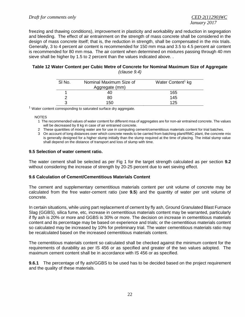
freezing and thawing conditions), improvement in plasticity and workability and reduction in segregation and bleeding. The effect of air entrainment on the strength of mass concrete shall be considered in the design of mass concrete itself; that is, the reduction in strength, shall be compensated in the mix trials. Generally, 3 to 4 percent air content is recommended for 150 mm msa and 3.5 to 4.5 percent air content is recommended for 80 mm msa. The air content when determined on mixtures passing through 40 mm sieve shall be higher by 1.5 to 2 percent than the values indicated above. .
Table 12 Water Content per Cubic Metre of Concrete for Nominal Maximum Size of Aggregate (clause 9.4)
Sl No. Nominal Maximum Size of Aggregate (mm)
Water Content1 kg
1 2 3
40 80
150
165 145 125
1 Water content corresponding to saturated surface dry aggregate.
NOTES
1 The recommended values of water content for different msa of aggregates are for non-air entrained concrete. The values will be decreased by 8 kg in case of air entrained concrete.
2 These quantities of mixing water are for use in computing cement/cementitious materials content for trial batches. 3 On account of long distances over which concrete needs to be carried from batching plant/RMC plant, the concrete mix
is generally designed for a higher slump initially than the slump required at the time of placing. The initial slump value shall depend on the distance of transport and loss of slump with time.
9.5 Selection of water cement ratio. The water cement shall be selected as per Fig 1 for the target strength calculated as per section 9.2 without considering the increase of strength by 20-25 percent due to wet sieving effect. 9.6 Calculation of Cement/Cementitious Materials Content The cement and supplementary cementitious materials content per unit volume of concrete may be calculated from the free water-cement ratio (see 9.5) and the quantity of water per unit volume of concrete. In certain situations, while using part replacement of cement by fly ash, Ground Granulated Blast Furnace Slag (GGBS), silica fume, etc, increase in cementitious materials content may be warranted, particularly if fly ash is 20% or more and GGBS is 30% or more. The decision on increase in cementitious materials content and its percentage may be based on experience and trials; or the cementitious materials content so calculated may be increased by 10% for preliminary trial. The water cementitious materials ratio may be recalculated based on the increased cementitious materials content. The cementitious materials content so calculated shall be checked against the minimum content for the requirements of durability as per IS 456 or as specified and greater of the two values adopted. The maximum cement content shall be in accordance with IS 456 or as specified. 9.6.1 The percentage of fly ash/GGBS to be used has to be decided based on the project requirement and the quality of these materials.
Draft for comments only CED 2(11290)WC
January 2017
23
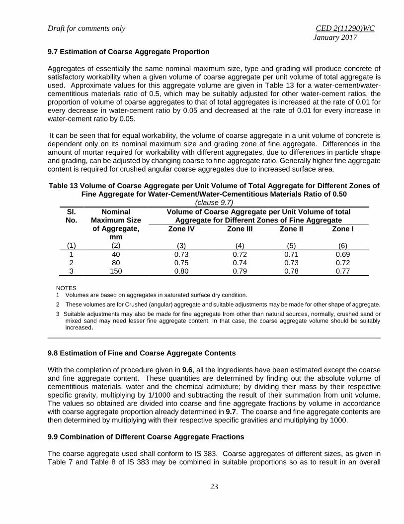
9.7 Estimation of Coarse Aggregate Proportion Aggregates of essentially the same nominal maximum size, type and grading will produce concrete of satisfactory workability when a given volume of coarse aggregate per unit volume of total aggregate is used. Approximate values for this aggregate volume are given in Table 13 for a water-cement/water-cementitious materials ratio of 0.5, which may be suitably adjusted for other water-cement ratios, the proportion of volume of coarse aggregates to that of total aggregates is increased at the rate of 0.01 for every decrease in water-cement ratio by 0.05 and decreased at the rate of 0.01 for every increase in water-cement ratio by 0.05. It can be seen that for equal workability, the volume of coarse aggregate in a unit volume of concrete is dependent only on its nominal maximum size and grading zone of fine aggregate. Differences in the amount of mortar required for workability with different aggregates, due to differences in particle shape and grading, can be adjusted by changing coarse to fine aggregate ratio. Generally higher fine aggregate content is required for crushed angular coarse aggregates due to increased surface area. Table 13 Volume of Coarse Aggregate per Unit Volume of Total Aggregate for Different Zones of
Fine Aggregate for Water-Cement/Water-Cementitious Materials Ratio of 0.50 (clause 9.7)
Sl. No.
(1)
Nominal Maximum Size of Aggregate,
mm (2)
Volume of Coarse Aggregate per Unit Volume of total Aggregate for Different Zones of Fine Aggregate
Zone IV
(3)
Zone III
(4)
Zone II
(5)
Zone I
(6)
1 40 0.73 0.72 0.71 0.69 2 80 0.75 0.74 0.73 0.72 3 150 0.80 0.79 0.78 0.77
NOTES 1 Volumes are based on aggregates in saturated surface dry condition.
2 These volumes are for Crushed (angular) aggregate and suitable adjustments may be made for other shape of aggregate.
3 Suitable adjustments may also be made for fine aggregate from other than natural sources, normally, crushed sand or mixed sand may need lesser fine aggregate content. In that case, the coarse aggregate volume should be suitably increased.
9.8 Estimation of Fine and Coarse Aggregate Contents With the completion of procedure given in 9.6, all the ingredients have been estimated except the coarse and fine aggregate content. These quantities are determined by finding out the absolute volume of cementitious materials, water and the chemical admixture; by dividing their mass by their respective specific gravity, multiplying by 1/1000 and subtracting the result of their summation from unit volume. The values so obtained are divided into coarse and fine aggregate fractions by volume in accordance with coarse aggregate proportion already determined in 9.7. The coarse and fine aggregate contents are then determined by multiplying with their respective specific gravities and multiplying by 1000. 9.9 Combination of Different Coarse Aggregate Fractions The coarse aggregate used shall conform to IS 383. Coarse aggregates of different sizes, as given in Table 7 and Table 8 of IS 383 may be combined in suitable proportions so as to result in an overall
Draft for comments only CED 2(11290)WC
January 2017
24
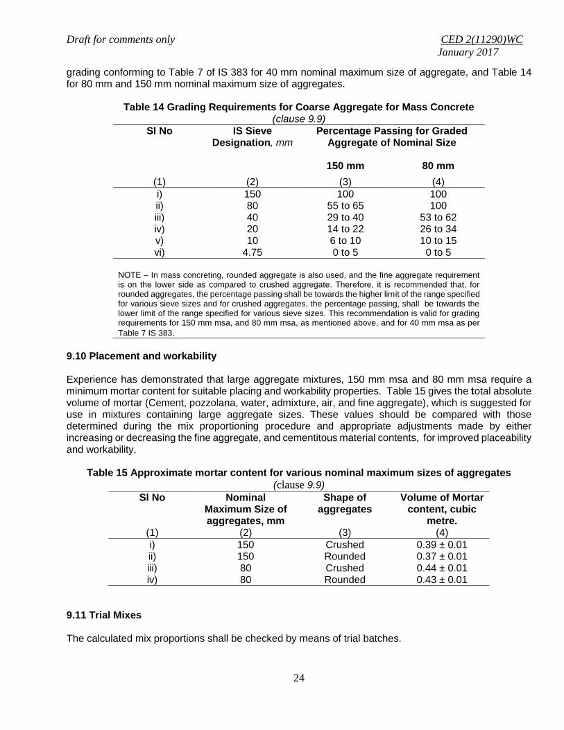
grading conforming to Table 7 of IS 383 for 40 mm nominal maximum size of aggregate, and Table 14 for 80 mm and 150 mm nominal maximum size of aggregates.
Table 14 Grading Requirements for Coarse Aggregate for Mass Concrete (clause 9.9)
Sl No IS Sieve Designation, mm
Percentage Passing for Graded Aggregate of Nominal Size
150 mm 80 mm
(1) (2) (3) (4)
i) 150 100 100 ii) 80 55 to 65 100 iii) 40 29 to 40 53 to 62 iv) 20 14 to 22 26 to 34 v) 10 6 to 10 10 to 15 vi) 4.75 0 to 5 0 to 5
NOTE ‒ In mass concreting, rounded aggregate is also used, and the fine aggregate requirement is on the lower side as compared to crushed aggregate. Therefore, it is recommended that, for rounded aggregates, the percentage passing shall be towards the higher limit of the range specified for various sieve sizes and for crushed aggregates, the percentage passing, shall be towards the lower limit of the range specified for various sieve sizes. This recommendation is valid for grading requirements for 150 mm msa, and 80 mm msa, as mentioned above, and for 40 mm msa as per
Table 7 IS 383.
9.10 Placement and workability Experience has demonstrated that large aggregate mixtures, 150 mm msa and 80 mm msa require a minimum mortar content for suitable placing and workability properties. Table 15 gives the total absolute volume of mortar (Cement, pozzolana, water, admixture, air, and fine aggregate), which is suggested for use in mixtures containing large aggregate sizes. These values should be compared with those determined during the mix proportioning procedure and appropriate adjustments made by either increasing or decreasing the fine aggregate, and cementitous material contents, for improved placeability and workability,
Table 15 Approximate mortar content for various nominal maximum sizes of aggregates
(clause 9.9)
Sl No Nominal Maximum Size of aggregates, mm
Shape of aggregates
Volume of Mortar content, cubic
metre. (1) (2) (3) (4)
i) 150 Crushed 0.39 ± 0.01 ii) 150 Rounded 0.37 ± 0.01 iii) 80 Crushed 0.44 ± 0.01 iv) 80 Rounded 0.43 ± 0.01
9.11 Trial Mixes The calculated mix proportions shall be checked by means of trial batches.

Draft for comments only CED 2(11290)WC
January 2017
25
Workability of the trial mix No. 1 shall be measured. The mix shall be carefully observed for freedom from segregation and bleeding and its finishing properties. If the measured workability of Trial Mix No. 1 is different from the stipulated value, the water and/or admixture content shall be adjusted suitably. With this adjustment, the mix proportion shall be recalculated keeping the free water-cement ratio at the pre-selected value, which will comprise Trial Mix No. 2. In additional two more Trial Mixes No. 3 and 4 shall be made with the water content same as Trial mix No. 2 and varying the free water-cement/cementitious materials ratio by about ± 10 percent of the preselected value, while satisfying the workability requirements as well. Mix No. 2 to 4 normally provides sufficient information, including the relationship between compressive strength and water-cement ratio, from which the mix proportions can be finalized, such that the strength and durability requirements are also satisfied. Additional field trials are recommended particularly for workability requirements. The concrete for field trials shall be produced by methods of actual concrete production. 9.12 ILLUSTRATIVE EXAMPLE An illustrative example of concrete mix proportioning for mass concreting is given in Annex E. This example is merely illustrative and explains the procedure to be adopted for mass concreting. The actual mix proportioning shall be based on various trials with the given materials

Draft for comments only CED 2(11290)WC
January 2017
26
ANNEX A
(clause 5.9)
ILLUSTRATIVE EXAMPLE ON CONCRETE MIX PROPORTIONING
An example illustrating the mix proportioning for a concrete of M40 grade is given in A.1 to A.12.
A. 1 STIPULATIONS FOR PROPORTOING
a) Grade designation : M 40 b) Type of cement : PPC conforming to IS 1489 (Part 2) c) Maximum nominal size of aggregate : 20 mm
d) Minimum cement content and maximum water-cement ratio to be adopted : Severe (for reinforced concrete)
and/or
Exposure conditions as per Table 3 and Table 5 of IS 456;
e) Workability : 75 mm (slump) f) Method of concrete placing : Chute (Non pumbable) j) Degree of site control : Good k) Type of aggregate : Crushed angular aggregate m) Maximum cement content (OPC Content) : 450 kg/m3 n) Chemical admixture type : Superplasticizer - normal
A.2 TEST DATA FOR MATERIALS
a) Cement used : PPC conforming to IS 1489 (Part 2) b) Specific gravity of cement : 2.88 c) Chemical admixture : Superplasticizer conforming to IS 9103 d) Specific gravity of:
i) Coarse aggregate : 2.74 ii) Fine aggregate : 2.65 iii) Chemical admixture : 1.145
e) Water absorption: i) Coarse aggregate : 0.5 percent ii) Fine aggregate : 1.0 percent
f) Free (surface) moisture:
i) Coarse aggregate : Nil (absorbed moisture also nil) ii) Fine aggregate : Nil (absorbed moisture also nil)
g) Sieve analysis: i) Coarse aggregate :
IS Sieve Sizes
Analysis of Coarse Aggregate Fraction
Percentage of Different Fractions Remarks

Draft for comments only CED 2(11290)WC
January 2017
27
mm
I
(20-10 mm)
II (10- 4.75
mm)
I 60 percent
II 40 percent
Conforming 100
percent
20 100 100 60 40 100
10 0 71.20 0 28.5 28.5 Conforming of Table 7 of
IS 383 4.75 9.40 3.7 3.7
2.36 0
2) Fine aggregate : Conforming to grading Zone II of
Table 9 of IS 383
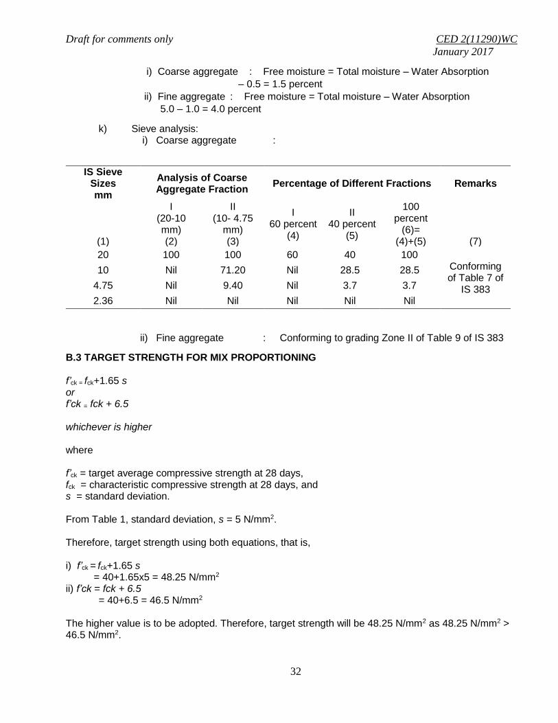
A.3 TARGET STRENGTH FOR MIX PROPORTIONING f’ck = fck+1.65 s or f’ck = fck + 6.5 whichever is higher
where f’ck = target average compressive strength at 28 days, fck = characteristic compressive strength at 28 days, and s = standard deviation. From Table 1, standard deviation, s = 5 N/mm2. Therefore, target strength using both equations, that is, i) f’ck = fck+1.65 s = 40+1.65x5 = 48.25 N/mm2
ii) f’ck = fck + 6.5 = 40+6.5 = 46.5 N/mm2
The higher value is to be adopted. Therefore, target strength will be 48.25 N/mm2 as 48.25 N/mm2 > 46.5 N/mm2.
A.4 APPROXIMATE AIR CONTENT From Table 3, the approximate amount of entrapped air to be expected in normal (non-air-entrained) concrete is 1.0 percent for 20mm nominal maximum size of aggregate.
A.5 SELECTION OF WATER-CEMENT RATIO From Fig. 1, the free water-cement ratio required for the target strength of 48.25 N/mm2 is 0.36 for OPC 43 grade curve. (For PPC, the strength corresponding to OPC 43 grade curve is assumed for the trial)

Draft for comments only CED 2(11290)WC
January 2017
28
This is lower than the maximum value of 0.45 prescribed for ‘Severe’ exposure for reinforced concrete as per Table 5 of IS 456. 0.36 < 0.45, hence O.K. A.6 SELECTION OF WATER CONTENT From Table 4, water content = 186 kg (for 50 mm slump) for 20 mm aggregate.
Estimated water content for 75 mm slump = 186 + 3 𝑥 186
100
= 191.58 kg As superplasticizer is used, the water content may be reduced, Based on trial data, the water content reduction of 23 percent is considered while using superplasticizer at the rate 1.0 percent by weight of cement..
Hence the water content = 191.58 x 0.77 = 147.52 kg, ≈ 148 kg A.7 CALCULATION OF CEMENT CONTENT Water-cement ratio = 0.36
Cement content = 148
0.36 = 411.11 kg/m3 ≈ 412 kg/m3
From Table 5 of IS 456, minimum cement content for ‘service’ exposure condition = 320 kg/m3 412 kg/m3 > 320 kg/m3, hence, O.K. A.8 PROPORTION OF VOLUME OF COARSE AGGREGATE AND FINE AGGREGETE CONTENT From Table 5, the proportionate volume of coarse aggregate corresponding to 20 mm size aggregate and fine aggregate (Zone II) for water-cement ratio of 0.50 = 0.62. In the present case water-cement ratio is 0.36. Therefore, volume of coarse aggregate is required to be increased to decrease the fine aggregate content. As the water-cement ratio is lower by 0.14, the proportion of volume of coarse, aggregate is increased by 0.028 (at the rate of -/+0.01 for every ± 0.05 change in water-cement ratio). Therefore, corrected proportion of volume of coarse aggregate for the water-cement ratio of 0.36 = 0.62 + 0.028 = .648.. Volume of fine aggregate content = 1 – 0.648 = 0.352 A.9 MIX CALCULATIONS The mix calculations per unit volume of concrete shall be as follows: a) Total Volume = 1 m3 b) Volume of entrapped air = 0.01 m3 in wet concrete

Draft for comments only CED 2(11290)WC
January 2017
29
c) Volume of cement = 1000
1
cement ofgravity
cement of
Specific
Mass
= 1000
1
88.2
412
= 0.143 m3
d) Volume of water = 1000
1
waterofgravity
waterof
Specific
Mass
=1000
1
1
148
= 0.148 m3 e) Volume of chemical admixture (superplasticizer) (@ 1.0 percent
by mass of cementitious material) = 1000
1
admixture ofgravity
admixture chemical of
Specific
Mass
= 1000
1
145.1
12.4
= 0.0036 m3
g) Volume of all in aggregate = [(a-b)-(c+d+e)} = [(1-0.01) – (0.143 + 0.148 + `0.0036) = 0.695 m3 h) Mass of coarse aggregate = g x Volume of coarse aggregate x Specific gravity of coarse aggregate x 1000 = 0.695 x 0.648 x 2.74 x 1000 = 1233.98 kg ≈ 1234 kg i) Mass of fine aggregate = g x volume of fine aggregate x Specific gravity of fine aggregate x 1000 = 0.695 x 0.352 x 2.65 x 1000 = 648.29 kg ≈ 648 kg A-10 MIX PROPORTIONS FOR TRIAL NUMBER 1 Cement = 412 kg/m3 Water (net mixing) = 148 kg/m3 Fine aggregate (SSD) = 648 kg/m3 Coarse aggregate (SSD) = 1234 kg/m3 Chemical admixture = 4.12 kg/m3, Free Water-cement ratio = 0.36

Draft for comments only CED 2(11290)WC
January 2017
30
NOTE – Aggregates should be used in saturated surface dry condition. If otherwise, when computing the requirement of mixing water, allowance shall be made for the free (surface) moisture contributed by the fine and coarse aggregates. On the other hand, if the aggregates are dry, the amount of mixing water should be increased by an amount equal to the moisture likely to be absorbed by the aggregates. Necessary adjustments are also required to be made in mass of aggregates. The surface water and percent water absorption of aggregates shall be determined according to IS 2386.
A-11 ADJUSTMENT ON WATER, FINE AGGREGATE & COARSE AGGREGATE (IF THE COARSE & FINE AGGREGATE IS IN DRY CONDITION)
Fine Aggregate (Dry) = Mass of fine aggregate in SSD condition / (1+ water absorption/100) = 648/ (1+ 1/100) = 648/1.01=641.58 ≈ 642 kg/m3
Coarse Aggregate (Dry) = Mass of coarse aggregate in SSD condition / (1+ water absorption/100) = 1234/ (1+ 0.5/100) = 1234/1.005 = 1227.86 ≈ 1228 kg/m3
The extra water to be added for absorption by coarse and fine aggregate, 1. For coarse aggregate = Mass of coarse aggregate in SSD condition – mass of coarse aggregate in
dry condition = 1234 - 1228 = 6 kg
2. For fine aggregate = Mass of fine aggregate in SSD condition – mass of fine aggregate in dry condition
= 648 - 642 = 6 kg The estimated requirement for added water, therefore, becomes = 148 + 6 + 6 = 160 kg/m3
MIX PROPORTIONS AFTER ADUSTMENT FOR DRY AGGREGATES
Cement = 412 kg/m3 Water (to be added) = 160 kg/m3 Fine aggregate (Dry) = 642 kg/m3 Coarse aggregate (Dry) = 1228 kg/m3 Chemical admixture = 4.12 kg/m3 Free Water-cement ratio = 0.36
A.12 The total mass of coarse aggregate shall be divided into two fractions of 20 - 10 mm and 10 - 4.75 mm, in a suitable ratio, to satisfy the overall grading requirements for 20 mm max size aggregate as per Table 7 of IS 383. In this example, the ratio works out to be 60:40 as shown under A.2 (g). A.13 The slump shall be measured and the water content and dosage of admixture shall be adjusted for achieving the required slump based on trial, if required. The mix proportions shall be reworked for the actual water content and checked for durability requirements. A.14 Two more trials having variation of ± 10 percent of water-cement ratio in A-10 shall be carried out and a graph between three water-cement ratios and their corresponding strengths shall be plotted to work out the mix proportions for the given target strength for field trials. However, durability requirement shall be met.

Draft for comments only CED 2(11290)WC
January 2017
31
ANNEX B
(clause 5.9)
ILLUSTRATIVE EXAMPLE OF MIX PROPORTIONING OF CONCRETE (USING FLY ASH AS PART REPLACEMENT OF OPC)
B.0 An example illustrating the mix proportioning for a concrete of M-40 grade using fly ash is given B.1 to B.14. B.1 STIPULATIONS FOR PROPORTIONING
a) Grade designation : M 40 b) Type of cement : OPC 43 grade conforming to IS 269 c) Type of mineral admixture : Fly ash conforming to IS 3812(Part1) d) Maximum nominal size of aggregate : 20 mm e) Minimum cement content and
maximum water-cement ratio to be adopted: Severe(for reinforced concrete)
and/or
Exposure conditions as per Table 3 and Table 5 of IS 456;
f) Workability : 120 mm (slump) g) Method of concrete placing : Pumping h) Degree of supervision : Good j) Type of aggregate : Crushed angular aggregate k) Maximum cement (OPC) content : 450 kg/m3 m) Chemical admixture type : Superplasticizer- normal
B.2 TEST DATA FOR MATERIALS a) Cement used : OPC 43 grade conforming to IS 269 b) Specific gravity of cement` : 3.15 c) Fly ash : Conforming to IS 3812 (Part 1) d) Specific gravity of fly ash : 2.2 e) Chemical admixture : Superplasticizer conforming to IS 9103 f) Specific gravity of :
i) Coarse aggregate : 2.74
ii) Fine aggregate : 2.65
iii) Chemical Admixture : 1.145
g) Water absorption: i) Coarse aggregate : 0.5 percent
ii) Fine aggregate : 1.0 percent
h) The coarse and fine aggregates are wet and their total moisture content is 2 percent and 5 percent respectively. Therefore, the free moisture content in coarse and fine aggregate shall be as shown in (j) below
j) Free (surface) moisture :
Draft for comments only CED 2(11290)WC
January 2017
32
i) Coarse aggregate : Free moisture = Total moisture – Water Absorption
– 0.5 = 1.5 percent
ii) Fine aggregate : Free moisture = Total moisture – Water Absorption
5.0 – 1.0 = 4.0 percent
k) Sieve analysis: i) Coarse aggregate :
IS Sieve Sizes mm
Analysis of Coarse Aggregate Fraction
Percentage of Different Fractions Remarks
(1)
I (20-10 mm) (2)
II (10- 4.75
mm) (3)
I 60 percent
(4)
II 40 percent
(5)
100 percent
(6)= (4)+(5)
(7)
20 100 100 60 40 100 Conforming of Table 7 of
IS 383
10 Nil 71.20 Nil 28.5 28.5
4.75 Nil 9.40 Nil 3.7 3.7
2.36 Nil Nil Nil Nil Nil
ii) Fine aggregate : Conforming to grading Zone II of Table 9 of IS 383
B.3 TARGET STRENGTH FOR MIX PROPORTIONING f’ck = fck+1.65 s or f’ck = fck + 6.5 whichever is higher
where f’ck = target average compressive strength at 28 days, fck = characteristic compressive strength at 28 days, and s = standard deviation. From Table 1, standard deviation, s = 5 N/mm2. Therefore, target strength using both equations, that is, i) f’ck = fck+1.65 s = 40+1.65x5 = 48.25 N/mm2 ii) f’ck = fck + 6.5 = 40+6.5 = 46.5 N/mm2
The higher value is to be adopted. Therefore, target strength will be 48.25 N/mm2 as 48.25 N/mm2 > 46.5 N/mm2.

Draft for comments only CED 2(11290)WC
January 2017
33
B.4 APPROXIMATE AIR CONTENT From Table 3, the approximate amount of entrapped air to be expected in normal (non-air-entrained) concrete is 1.0 percent for 20mm nominal maximum size of aggregate. B.5 SELECTION OF WATER-CEMENT RATIO From Fig. 1, the free water-cement ratio required for the target strength of 48.25 N/mm2 is 0.36 for OPC 43 grade curve. This is lower than the maximum value of 0.45 prescribed for ‘Severe’ exposure for reinforced concrete as per Table 5 of IS 456. 0.36 < 0.45, hence O.K. B.6 SELECTION OF WATER CEMENT From Table 4, water content = 186 kg (for 50 mm slump) for 20 mm aggregate. Estimated water content for 120 mm slump (increasing at the rate of 3% for every 25 mm slump)
= 186100
4.8186
= 201.62 kg
As superplasticizer is used, the water content may be reduced, Based on trial data, the water content reduction of 23 percent is considered while using superplasticizer at the rate 1.0% by weight of cement. Hence the arrived water content = 201.62 x 0.77 = 155.25 kg ≈ 155 kg B.7 CALCULATION OF CEMENT CONTENT Water-cement ratio = 0.36
Cement content = 36.0
155
= 430.55 kg/m3 ≈ 431 kg/m3 From Table 5 of IS 456, minimum cement content for ‘service’ exposure condition = 320 kg/m3 431 kg/m3 > 320 kg/m3, hence, O.K. To proportion a mix containing fly ash the following steps are suggested:
a) Decide the percentage fly ash to be used based on project requirement and quality of fly ash b) In certain situations increase in cementitious material content may be warranted. The decision on increase in cementitious material content and its percentage may be based on experience and trial
NOTE – This illustrative example is with increase of 10 percent cementitious material content.
Cementitious material content = 431 x 1.10 = 474.1 kg/m3 ≈ 474 kg/m3 Water Content = 155 kg/m3
So, water-cementitious ratio = 0.327474
155

Draft for comments only CED 2(11290)WC
January 2017
34
Fly ash@ 30 percent of total cementitious material content = 474 x 30% = 142.2 ≈ 142 kg/m3
Cement (OPC) = 474 – 142 = 332 kg/m3 B.8 PROPORTION OF VOLUME OF COARSE AGGREGATE AND FINE AGGREGETE CONTENT From Table 5, volume of coarse aggregate corresponding to 20 mm size aggregate and fine aggregate (Zone II) for water-cement ratio of 0.50 = 0.62. In the present case water-cementitious ratio is 0.327. Therefore, volume of coarse aggregate is required to be increased to decrease the fine aggregate content. As the water-cement ratio is lower by 0.173, the proportion of volume of coarse aggregate is increased by 0.0346 (at the rate of -/+0.01 for every ± 0.05 change in water-cement ratio). Therefore, corrected proportion of volume of coarse aggregate for the water-cementitious ratio of 0.327 = 0.62 +0.0346 = 0.6546. For pumpable concrete these values may be reduced by upto 10 percent. (see 5.5.1). Here, 10 percent reduction is considered. Therefore, volume of coarse aggregate = 0.6546 x 0.9 = 0.5891 say 0.59 Volume of fine aggregate content = 1 – 0.59 = 0.41 B.9 MIX CALCULATIONS The mix calculations per unit volume of concrete shall be as follows: a) Total Volume = 1 m3 b) Volume of entrapped air = 0.01 m3 in wet concrete
c) Volume of cement = 1000
1
cement ofgravity
cement of
Specific
Mass
= 1000
1
15.3
332
= 0.105 m3
d) Volume of fly ash = 1000
1
ashfly ofgravity
ashfly of
Specific
Mass
=1000
1
2.2
142
= 0.0645 m3
e) Volume of water = 1000
1
waterofgravity
waterof
Specific
Mass
= 1000
1
1
155
= 0.155 m3

Draft for comments only CED 2(11290)WC
January 2017
35
f) Volume of chemical admixture (superplasticizer) (@ 1.0 %
by mass of cementitious material) = 1000
1
admixture ofgravity
admixture chemical of
Specific
Mass
= 1000
1
145.1
74.4
= 0.004 m3 g) Volume of all in aggregate = [(a-b)-(c + d + e + f)} = (1-0.01)-(0.105+0.0645+0.155+0.004) = 0.6615 m3 h) Mass of coarse aggregate = g x Volume of coarse aggregate x Specific gravity of coarse aggregate x 1000 = 0.6615 x 0.59 x 2.74 x 1000 = 1 069.38 kg ≈ 1 069 kg j) Mass of fine aggregate = g x volume of fine aggregate x Specific gravity of fine
aggregate x 1000 = 0.6551 x 0.41 x 2.65 x 1000 = 718.71 ≈ 719 kg
B.10 MIX PROPORTIONS FOR TRIAL NUMBER 1 Cement = 332 kg/m3 Fly Ash = 142 kg/m3
Water (Net mixing) = 155 kg/m3 Fine aggregate (SSD = 719 kg/m3 Coarse aggregate (SSD) = 1 069 kg/m3 Chemical admixture = 4.74 kg/m3 Free Water-cementitious materials ratio = 0.327
NOTE – Aggregates should be used in saturated surface dry condition. If otherwise, when computing the requirement of mixing water, allowance shall be made for the free (surface) moisture contributed by the fine and coarse aggregates. On the other hand, if the aggregates are dry, the amount of mixing water should be increased by an amount equal to the moisture likely to be absorbed by the aggregates. Necessary adjustments are also required to be made in mass of aggregates. The surface water and percent water absorption of aggregates shall be determined according to IS 2386 (Part 3).
B.11 ADJUSTMENT ON WATER, FINE AGGREGATE & COARSE AGGREGATE
(IF THE COARSE & FINE AGGREGATE IS IN WET CONDITION) Fine Aggregate (Wet) ‒ Mass of wet fine aggregate = mass of fine aggregate in SSD condition x (1+ Free (surface) moisture/100)
= 719 x (1+4/100) = 747.76 kg/m3 ≈ 748 kg/m3
Coarse Aggregate (Wet) ‒ Mass of wet coarse aggregate = mass of coarse aggregate in SSD condition x (1+ Free (surface) moisture/100 )
= 1069 x (1+1.5/100) = 1085.03 kg/m3 ≈ 1085 kg/m3

Draft for comments only CED 2(11290)WC
January 2017
36
The coarse and fine aggregates, being wet, contribute water to the mix to the extent of free moisture over SSD condition. The quantity of this water is required to be subtracted from the calculated water content.
1. Water content contributed by wet coarse aggregate = Mass of wet coarse aggregate – mass of SSD condition coarse aggregate = 1085 – 1069 = 16 kg 2. Water content contributed by wet fine aggregate = Mass of wet fine aggregate – mass of SSD condition fine aggregate = 748 – 719 = 29 kg
The requirement for added water becomes : = 155 - 16 - 29 = 110 kg/m3
MIX PROPORTIONS AFTER ADUSTMENT FOR WET AGGREGATES
Cement = 332 kg/m3 Flyash = 142 kg/m3 Water (to be added) = 110 kg/m3 Fine aggregate (Wet) = 748 kg/m3 Coarse aggregate (Wet) = 1085 kg/m3 Chemical admixture = 4.74 kg/m3
Free Water-cementitious materials ratio= 0.327 B.12 The total mass of coarse aggregate shall be divided into two fractions of 20 - 10 mm and 10 - 4.75 mm, in a suitable ratio, to satisfy the overall grading requirements for 20 mm max size aggregate as per Table 7 of IS 383. In this example, the ratio works out to be 60:40 as shown under B.2 (k). B-13 The slump shall be measured and the water content and dosage of admixture shall be adjusted for achieving the required slump based on trial, if required. The mix proportions shall be reworked for the actual water content and checked for durability requirements. B-14 Two more trials having variation of ± 10 percent of water-cementitious materials ratio in B.10 shall be carried out and a graph between these water-cementitious materials ratios and their corresponding strengths shall be plotted to work out the mix proportions for the given target strength for field trials. However, durability requirement shall be met.

Draft for comments only CED 2(11290)WC
January 2017
37
ANNEX C
(clause 6.4)
ILLUSTRATIVE EXAMPLE ON CONCRETE MIX PROPORTIONING FOR HIGH STRENGTH CONCRETE
An example illustrating the mix proportioning for a concrete of M 70 grade using silica fume and fly ash is given below. Use of silica fume is generally advantageous for grades of concrete M50 and above and for high performance concrete with special requirements, like. higher abrasion resistance of concrete. C.1 STIPULATIONS FOR PROPORTIONING
a) Grade designation : M 70 b) Type of cement : OPC 53 grade conforming to IS 269 c) Silica fume : Conforming to IS 15388 d) Maximum nominal size of aggregate : 20 mm e) Exposure conditions as per Table 3 : Severe (for reinforced concrete) and Table 5 of IS 456; f) Workability : 120 mm (slump) g) Method of concrete placing : Pumping h) Degree of supervision : Good j) Type of aggregate : Crushed angular aggregate k) Maximum cement (OPC) content : 450 kg/m3 l) Chemical admixture type : Superplasticizer (Polycarboxylate ether based)
C.2 TEST DATA FOR MATERIALS
a) Cement used : OPC conforming to IS 269 b) Specific gravity of cement : 3.15 c) Specific gravity of:
i) Coarse aggregate : 2.74 ii) Fine aggregate : 2.65 iii) Fly ash : 2.20 iv) silica fume : 2.20 v) chemical admixture : 1.08
d) Water absorption: i) Coarse aggregate : 0.5 percent ii) Fine aggregate : 1.0 percent
f) Free (surface) moisture:
i) Coarse aggregate : Nil (absorbed moisture also nil)
ii) Fine aggregate : Nil (absorbed moisture also nil)
g) Sieve analysis: i) Coarse aggregate :
IS Sieve Sizes mm
Analysis of Coarse Aggregate Fraction
Percentage of Different Fractions Remarks
I II I
50 percent II
50 percent 100 percent

Draft for comments only CED 2(11290)WC
January 2017
38
C.3 TARGET STRENGTH FOR MIX PROPORTIONING f’ck = fck+1.65 s or f’ck = fck + X whichever is higher
where f’ck = target average compressive strength at 28 days, fck = characteristic compressive strength at 28 days, and s = standard deviation. From Table 1, standard deviation,s = 6.0 N/mm2. Therefore, target strength using both equations i.e. i) f’ck = fck+1.65 s = 70+1.65x6.0 = 79.9 N/mm2 ii) f’ck = fck + 8.0 (The value of X for M 70 grade as per Table 2 is 8.0 N/mm2 ) = 70+8.0 = 78.0 N/mm2
The higher value is to be adopted. Therefore, target strength will be 79.9 N/mm2 as 79.9 N/mm2 > 78.0 N/mm2. C.4 APPROXIMATE AIR CONTENT From Table 6, the approximate amount of entrapped air to be expected in normal (non-air-entrained) concrete is 0.5 % for 20.0 mm nominal maximum size of aggregate. C.5 SELECTION OF WATER-CEMENTIOUS MATERIALS RATIO From Table 8, the water-cementitious materials ratio required for the target strength of 79.9 N/mm2 is 0.29 for MSA 20 mm. This is lower than the maximum value of 0.45.
(1)
(20-10 mm) (2)
(10- 4.75 mm) (3)
(4)
(5)
(6)=(4)+(5)
(7)
20
100
100
50
50
100 Conforming
of Table 7 of IS 383
10 2.8 78.3 1.4 39.15 40.55
4.75 Nil 8.70 Nil 4.35 4.35
ii) Fine aggregate : Conforming to grading Zone II of Table 9 of IS 383

Draft for comments only CED 2(11290)WC
January 2017
39
0.29 < 0.45, hence O.K. C.6 SELECTION OF WATER CONTENT From Table 7, water content for 20 mm aggregate = 186 kg/m3 (for 50mm slump without using superplasticiser)
Estimated water content for 120 mm slump = 186100
4.8186
= 201.624 ≈ 202 kg/m3 As superplasticizer (Polycarboxylate ether based) is used, the water content can be reduced by 30 percent. Hence, the reduced water content = 202 x 0.70 = 141.4 kg/m3 ≈ 141 kg/m3 C.7 CALCULATION OF CEMENT CONTENT Water–cement ratio = 0.29 Water content = 141 kg/m3 Cement content = 141 / 0.29 = 486.2 ≈ 486 kg/m3 It is proposed to add 15 percent fly ash in the mix, in such situations increase in cementitious material content may be warranted. The decision on increase in cementitious material content and its percentage may be based on experience and trial. NOTE – This illustrative example is with increase of 10 percent cementitious material content.
The cementitious material content = 486 x 1.05 = 534.6 ≈ 535 kg/m3
Fly Ash @ 15 percent by weight of Cementitious Material = 535 x 15% = 80.25 kg/m3
Silica fume content @ 5 percent by weight of revised cementitious material = 535 x 5% = 26.75 kg/m3
Cement Content = 535- 26.75 – 80.25= 428 kg/m3
Revised w/cm = 141/535 = 0.264 Check for minimum cementitious materials content, 320kg/m3 < 535kg/m3 (428 kg/m3 OPC+ 26.75 kg/m3 silica fume + 80.25 kg/m3 fly ash) Hence, OK Check for maximum cement(OPC) content, 450 kg/m3 >428 kg/m3. Hence, OK. C.8 PROPORTION OF VOLUME OF COARSE AGGREGATE AND FINE AGGREGATE CONTENT From Table 10, Volume of coarse aggregate corresponding to 20 mm size aggregate and fine aggregate grading Zone II = 0.66 per unit volume of total aggregate. This is valid for water-cementitious materials ratio of 0.30. As water-cementitious material ratio is actually 0.264, the ratio is taken as 0.667. Volume of fine aggregate content = 1 – 0.667 = 0.333 per unit volume of total aggregate

Draft for comments only CED 2(11290)WC
January 2017
40
C.9 MIX CALCULATIONS a) Total Volume = 1 m3 b) Volume of entrapped air = 0.005 m3 in wet concrete
c) Volume of cement = 1000
1
cement ofgravity
cement of
Specific
Mass
= 1000
1
15.3
428
= 0.135 m3
d) Volume of water = 1000
1
waterofgravity
waterof
Specific
Mass
=1000
1
1
141
= 0.141 m3
e) Volume of silica fume = Mass of silicafume
Specific gravity of silicafume x
1
1000
= (26.75/2.2) x 1/1000 = 0.0122 m3
f) Volume of fly ash = Mass of fly ash
Specific gravity of fly ash x
1
1000
= (80.25/2.2) x 1/1000 = 0.0365 m3
g) Volume of chemical admixture (superplasticizer) (@ 0.5 percent
by mass of cementitious material) = 1000
1
admixture ofgravity
admixture chemical of
Specific
Mass
=(535 𝑥 0.5%)
1.08 x
1
1000
= 0.0024 m3
h) Volume of all in aggregate = [(a-b)-(c+d+e+ f+g)} = [(1-0.005) – (0.135 + 0.141 + `0.0122 + 0.0365 + 0.0024) = 0.668 m3 j) Mass of coarse aggregate = h x Volume of coarse aggregate x Specific gravity of coarse aggregate x 1000 = 0.668 x 0.667 x 2.74 x 1000 = 1220.82 kg ≈ 1221 kg k) Mass of fine aggregate = h x volume of fine aggregate x Specific gravity of fine aggregate x 1000

Draft for comments only CED 2(11290)WC
January 2017
41
= 0.668 x 0.333 x 2.65 x 1000 = 589.47 kg ≈ 589 kg
C.9.1 MIX PROPORTIONS FOR TRIAL NUMBER 1 ON AGGREGATE IN SSD CONDITION Cement = 428 kg/m3 Silica fume = 34 kg/m3
Water = 141 kg/m3
Fine Aggregate = 589 kg/m3
Coarse Aggregate = 1220 kg/m3
Chemical Admixture = 2.67 kg/m3
w/cm = 0.264
NOTE – Aggregates should be used in saturated surface dry condition. If otherwise, when computing the requirement of mixing water, allowance shall be made for the free (surface) moisture contributed by the fine and coarse aggregates. On the other hand, if the aggregates are dry, the amount of mixing water should be increased by an amount equal to the moisture likely to be absorbed by the aggregates. Necessary adjustments are also required to be made in mass of aggregates. The surface water and percent water absorption of aggregates shall be determined according to IS 2386 (Part
3).
C.10 The total mass of coarse aggregate shall be divided into two fractions of 20 - 10 mm and 10 - 4.75 mm, in a suitable ratio, to satisfy the overall grading requirements for 20 mm max size aggregate as per Table 7 of IS 383. In this example, the ratio works out to be 50:50 as shown under C.2 (g). C-11 The slump shall be measured and the water content and dosage of admixture shall be adjusted for achieving the required slump based on trial, if required. The mix proportions shall be reworked for the actual water content and checked for durability requirements. C-12 Two more trials having variation of ± 10 percent of water-cementitious materials ratio in C.9.1 shall be carried out and a graph between these water-cementitious materials ratios and their corresponding strengths shall be plotted to work out the mix proportions for the given target strength for field trials. However, durability requirement shall be met.

Draft for comments only CED 2(11290)WC
January 2017
42
ANNEX D (clause 8.4)
ILLUSTRATIVE EXAMPLE ON CONCRETE MIX PROPORTIONING FOR SCC
An example illustrating the mix proportioning procedure for SCC concrete is given in D.1 to D.13.
D. 1 STIPULATIONS FOR PROPORTOING
a) Grade designation : M 30 b) Type of cement : OPC 43 grade conforming to IS 269 c) Nominal maximum size of aggregate : 20 mm
d) Exposure conditions as per Table 3 : Severe (for reinforced concrete) and Table 5 of IS 456
e) Characteristics of SCC i) Slump flow class : SF3 (slump flow 760 mm – 850 mm) ii) Passing ability by L box test : Ratio of h2/h1 0.9 iii) V- Funnel flow time (Viscosity) : Class V1 (flow time ≤ 8s) iv) Sieve Segregation Resistance : SR2( ≤15percent)
f) Degree of site control : Good g) Type of aggregate : Crushed angular aggregate h) Maximum cement content (OPC Content) : 450 kg/m3 j) Chemical admixture type
i) Superplasticizer - normal (PCE type) ii) Viscosity modifying agent
k) Mineral admixture : Fly ash conforming to IS 3812 (Part 1)
D.2 TEST DATA FOR MATERIALS
a) Cement used : OPC 43 Grade conforming to IS 269 b) Specific gravity of cement : 3.15 c) Chemical admixture : Superplasticizer conforming to IS 9103 d) Specific gravity of:
i) Coarse aggregate : 2.74 ii) Fine aggregate : 2.65 iii) Chemical admixture : 1.08
e) Water absorption: i) Coarse aggregate : 0.5 percent ii) Fine aggregate : 1.0 percent
f) Free (surface) moisture
i) Coarse aggregate : Nil (absorbed moisture also nil)
ii) Fine aggregate : Nil (absorbed moisture also nil)
g) Sieve analysis: i) Coarse aggregate :

Draft for comments only CED 2(11290)WC
January 2017
43
IS Sieve Sizes mm
Analysis of Coarse Aggregate Fraction
Percentage of Different Fractions Remarks
(1)
I (20-10 mm) (2)
II (10- 4.75
mm) (3)
I 50 percent
(4)
II 50 percent
(5)
100 percent
(6)=(4)+(5)
(7)
20
100
100
50
50
100 Conforming
of Table 7 of IS 383
10 2.8 78.3 1.4 39.15 40.55
4.75 Nil 8.70 Nil 4.35 4.35
IS Sieve Sizes mm
Analysis of Coarse Aggregate Fraction
Percentage of Different Fractions Remarks
(1)
I (20-10 mm) (2)
II (10- 4.75
mm) (3)
I 50 percent
(4)
II 50 percent
(5)
100 percent
(6)= (4)+(5)
(7)
20 100 100 60 40 100
Conforming of Table 7 of
IS 383
10 0 71.20 0 28.5 28.5
4.75 9.40 3.7 3.7
2.36 0
ii) Fine aggregate : Conforming to grading Zone II of Table 9 of IS
383 (materials less than 0.125 mm is 8 percent, based on sieve analysis)
D.3 TARGET STRENGTH FOR MIX PROPORTIONING f’ck = fck+1.65 s or f’ck = fck + 6.5 whichever is higher
where f’ck = target average compressive strength at 28 days, fck = characteristic compressive strength at 28 days, and s = standard deviation. From Table 1, standard deviation, s = 5 N/mm2. Therefore, target strength using both equations i.e. i) f’ck = fck+1.65 s = 30+1.65x5 = 38.25 N/mm2 ii) f’ck = fck + 5

Draft for comments only CED 2(11290)WC
January 2017
44
= 30+6.5 = 36.5 N/mm2 The higher value is to be adopted. Therefore, target strength will be 38.25 N/mm2 as 38.25 N/mm2 > 36.5 N/mm2. D.4 APPROXIMATE AIR CONTENT From Table 3, the approximate amount of entrapped air to be expected in normal (non-air-entrained) concrete is 1.0 percent for 20mm nominal maximum size of aggregate.
D.5 SELECTION OF WATER-CEMENT RATIO From Fig. 1, the free water-cement ratio required for the target strength of 38.25 N/mm2 is 0.43 for OPC 43 grade curve. This is lower than the maximum value of 0.45 prescribed for ‘Severe’ exposure for reinforced concrete as per Table 5 of IS 456. 0.43 < 0.45, hence O.K. D.6 The initial mix shall be first estimated based on the typical ranges of mix constituents as per 8.3 and keeping in view, the characteristics of the fresh concrete such as flowability, passing ability, segregation resistance and viscosity as per the data for the mix proportioning in D.1. The initial mix shall be tested for various characteristics as per IS 1199 and adjustments to the initial mix shall be made till satisfactory characteristics are achieved. The various mix design parameters given in this example are only indicative and it may be necessary to carry out adjustments to these parameters during the use of the concrete mix at the project site. D.7 PROPORTIONING FOR INITIAL MIX D.7.1 Selection of Water Content and cement/fly ash content Generally, water requirement for SCC varies between 150 to 210 kg/m3. Since the class of slump flow is specified to be SF3 having a slump flow between 750 to 850 mm. This type of flow will be possible with a higher water content. To start with, a water content of 190 kg/m3 is selected for the initial mix. This water content of 190 kg/m3 will correspond to a cement content of 442 kg/m3 for water cement ratio of 0.43 as worked out in D.5. The cement content of 442 kg/m3 can be further divided into OPC and fly ash. Generally fly ash content of 25 to 50 percent is adopted for SCC. In this illustration, as the cement content is on the higher side, the fly ash content is taken as 35 percent. Therefore, the OPC content is for 287 kg/m3 and fly ash content will be 155 kg/m3. D.7.2 Selection of Admixture Content Taking an admixture dose of 0.6 percent by mass of cementitious material, the mass of admixture = 0.6/100 x 442 = 2.65 kg/m3. D.7.3 Selection of Powder Content and fine aggregate content The powder content (fines < 0.125 mm) required for SCC is generally in the range of 400 to 600 kg/m3. Since, the SR of class 1 and viscosity of V1 is required; the mix shall be sufficiently cohesive, (having
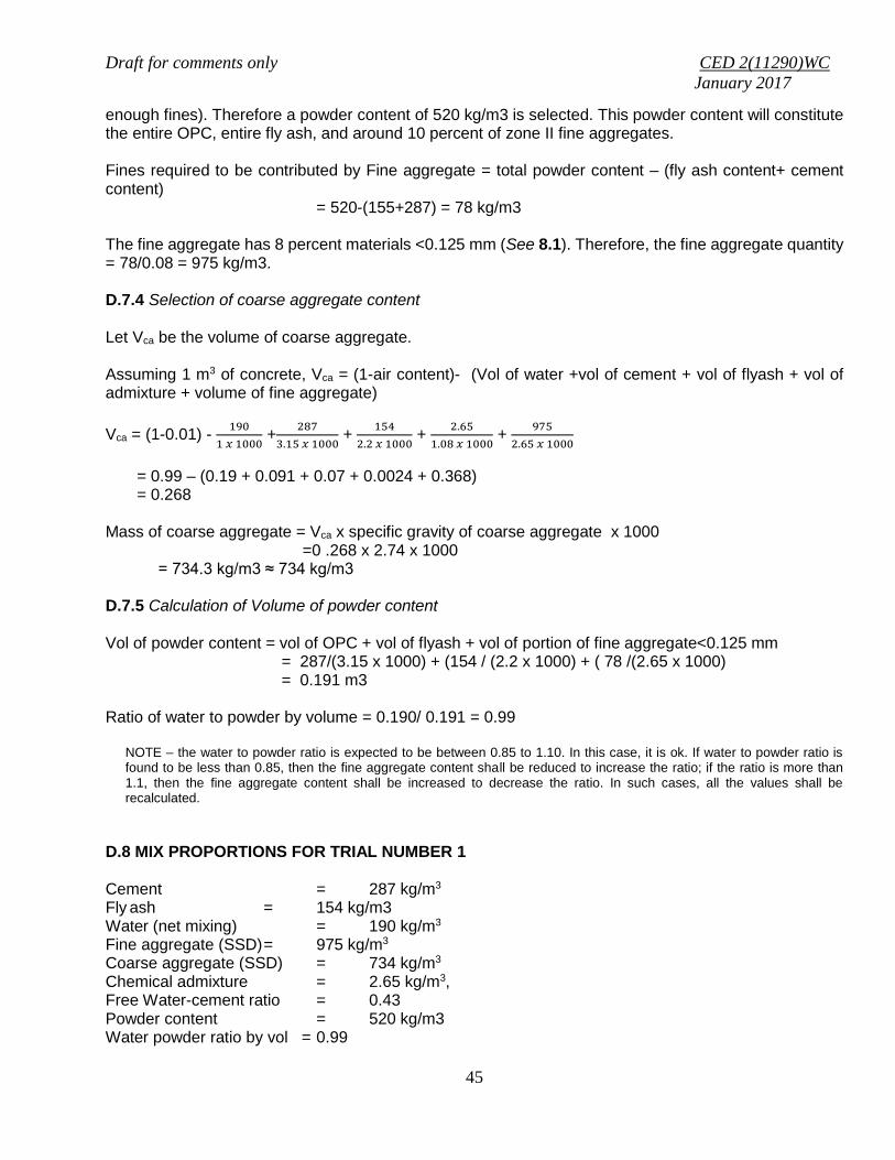
Draft for comments only CED 2(11290)WC
January 2017
45
enough fines). Therefore a powder content of 520 kg/m3 is selected. This powder content will constitute the entire OPC, entire fly ash, and around 10 percent of zone II fine aggregates. Fines required to be contributed by Fine aggregate = total powder content – (fly ash content+ cement content) = 520-(155+287) = 78 kg/m3 The fine aggregate has 8 percent materials <0.125 mm (See 8.1). Therefore, the fine aggregate quantity = 78/0.08 = 975 kg/m3. D.7.4 Selection of coarse aggregate content Let Vca be the volume of coarse aggregate. Assuming 1 m3 of concrete, Vca = (1-air content)- (Vol of water +vol of cement + vol of flyash + vol of admixture + volume of fine aggregate)
Vca = (1-0.01) - 190
1 𝑥 1000 +
287
3.15 𝑥 1000 +
154
2.2 𝑥 1000 +
2.65
1.08 𝑥 1000 +
975
2.65 𝑥 1000
= 0.99 – (0.19 + 0.091 + 0.07 + 0.0024 + 0.368) = 0.268 Mass of coarse aggregate = Vca x specific gravity of coarse aggregate x 1000 =0 .268 x 2.74 x 1000
= 734.3 kg/m3 ≈ 734 kg/m3 D.7.5 Calculation of Volume of powder content Vol of powder content = vol of OPC + vol of flyash + vol of portion of fine aggregate<0.125 mm = 287/(3.15 x 1000) + (154 / (2.2 x 1000) + ( 78 /(2.65 x 1000) = 0.191 m3 Ratio of water to powder by volume = 0.190/ 0.191 = 0.99
NOTE – the water to powder ratio is expected to be between 0.85 to 1.10. In this case, it is ok. If water to powder ratio is found to be less than 0.85, then the fine aggregate content shall be reduced to increase the ratio; if the ratio is more than 1.1, then the fine aggregate content shall be increased to decrease the ratio. In such cases, all the values shall be recalculated.
D.8 MIX PROPORTIONS FOR TRIAL NUMBER 1
Cement = 287 kg/m3
Fly ash = 154 kg/m3 Water (net mixing) = 190 kg/m3 Fine aggregate (SSD) = 975 kg/m3 Coarse aggregate (SSD) = 734 kg/m3 Chemical admixture = 2.65 kg/m3, Free Water-cement ratio = 0.43
Powder content = 520 kg/m3 Water powder ratio by vol = 0.99

Draft for comments only CED 2(11290)WC
January 2017
46
NOTE ‒ Aggregates should be used in saturated surface dry condition. If otherwise, when computing the requirement of mixing water, allowance shall be made for the free (surface) moisture contributed by the fine and coarse aggregates. On the other hand, if the aggregates are dry, the amount of mixing water should be increased by an amount equal to the moisture likely to be absorbed by the aggregates. Necessary adjustments are also required to be made in mass of aggregates. The surface water and percent water absorption of aggregates shall be determined according to IS 2386.
D.9 The total mass of coarse aggregate shall be divided into two fractions of 20 - 10 mm and 10 - 4.75 mm, in a suitable ratio, to satisfy the overall grading requirements for 20 mm max size aggregate as per Table 7 of IS 383. In this example, the ratio works out to be 50:50 as shown under D.2 (g). D.10 The various tests for flowability (slump flow test),for passing ability (L box test), for sieve segregation resistance and for viscosity (V funnel) shall be carried out and the values obtained shall be verified as per the data given in D.1 (e). In the event that satisfactory performance is not obtained, the initial mix shall be redesigned. Depending on the apparent problem, the following courses of action might be appropriate:
a) Adjust the cement/powder ratio and the water/powder ratio and test the flow and other properties of the paste. b) Try different types of addition (if available). c) Adjust the proportions of the fine aggregate and the dosage of superplasticiser. d) Consider using a viscosity modifying agent to reduce sensitivity of the mix. e) Adjust the proportion or grading of the coarse aggregate.
In the present case, based on trials the need was felt to use a small does(0.2% by weight of cementitious materials) of viscosity modifying agent to improve sensitivity of the mix, I,e, improve the cohesiveness of the mix. D.11 Two more trials having variation of ± 10 percent of water-cement ratio in D-10 shall be carried out and a graph between three water-cement ratios and their corresponding strengths shall be plotted to work out the mix proportions for the given target strength for field trials. However, durability requirement shall be met.
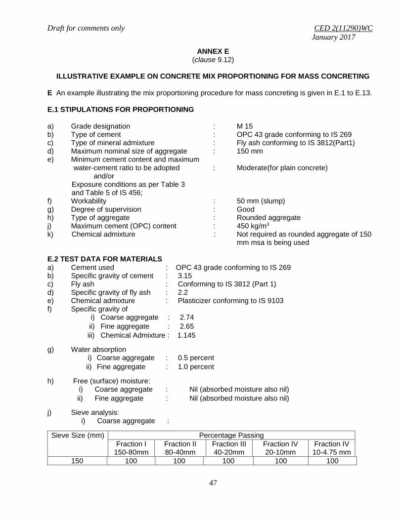
Draft for comments only CED 2(11290)WC
January 2017
47
ANNEX E (clause 9.12)
ILLUSTRATIVE EXAMPLE ON CONCRETE MIX PROPORTIONING FOR MASS CONCRETING
E An example illustrating the mix proportioning procedure for mass concreting is given in E.1 to E.13.
E.1 STIPULATIONS FOR PROPORTIONING a) Grade designation : M 15 b) Type of cement : OPC 43 grade conforming to IS 269 c) Type of mineral admixture : Fly ash conforming to IS 3812(Part1) d) Maximum nominal size of aggregate : 150 mm e) Minimum cement content and maximum water-cement ratio to be adopted : Moderate(for plain concrete) and/or Exposure conditions as per Table 3 and Table 5 of IS 456; f) Workability : 50 mm (slump) g) Degree of supervision : Good h) Type of aggregate : Rounded aggregate j) Maximum cement (OPC) content : 450 kg/m3 k) Chemical admixture : Not required as rounded aggregate of 150
mm msa is being used E.2 TEST DATA FOR MATERIALS a) Cement used : OPC 43 grade conforming to IS 269 b) Specific gravity of cement : 3.15 c) Fly ash : Conforming to IS 3812 (Part 1) d) Specific gravity of fly ash : 2.2 e) Chemical admixture : Plasticizer conforming to IS 9103 f) Specific gravity of
i) Coarse aggregate : 2.74
ii) Fine aggregate : 2.65
iii) Chemical Admixture : 1.145
g) Water absorption i) Coarse aggregate : 0.5 percent
ii) Fine aggregate : 1.0 percent
h) Free (surface) moisture: i) Coarse aggregate : Nil (absorbed moisture also nil)
ii) Fine aggregate : Nil (absorbed moisture also nil)
j) Sieve analysis: i) Coarse aggregate :
Sieve Size (mm) Percentage Passing
Fraction I 150-80mm
Fraction II 80-40mm
Fraction III 40-20mm
Fraction IV 20-10mm
Fraction IV 10-4.75 mm
150 100 100 100 100 100

Draft for comments only CED 2(11290)WC
January 2017
48
80 Nil 92 100 100 100
40 Nil 5 90 100 100
20 - Nil 4 97 100
10 - - Nil 10 78
4.75 - - - 2 10
ii) Fine aggregate : Conforming to grading Zone II of Table 9 of IS 383
E.3 TARGET STRENGTH FOR MIX PROPORTIONING f’ck = fck+1.65 s or f’ck = fck + 6.5 whichever is higher
where f’ck = target average compressive strength at 28 days, fck = characteristic compressive strength at 28 days, and s = standard deviation. From Table 1, standard deviation, s = 3.5 N/mm2. Therefore, target strength using both equations, that is, i) f’ck = fck+1.65 s = 15+1.65x3.5 = 20.77 N/mm2
ii) f’ck = fck + 5 = 15+5 = 20 N/mm2
The higher value is to be adopted. Therefore, target strength will be 20.77 N/mm2 as 20.77 N/mm2 > 20 N/mm2. Increase in target strength due to wet sieving through 40 mm size sieve, as per 9.2 = 25 % Therefore, final target strength = 20.77 x 1.25 = 26.0 N/mm2
NOTE -- This increase in target strength due to wet sieving effect is only for cube test results and not to be considered for selection of water cement ratio.
E.4 APPROXIMATE AIR CONTENT From Table 11, the approximate amount of entrapped air to be expected in normal (non-air-entrained) concrete is 0.2 percent for 150mm nominal maximum size of aggregate. E.5 SELECTION OF WATER-CEMENT RATIO

Draft for comments only CED 2(11290)WC
January 2017
49
From Fig. 1, the free water-cement ratio required for the target strength of 20.77 N/mm2 is 0.61 for OPC 43 grade curve. This is higher than the maximum value of 0.6 prescribed for ‘Moderate’ exposure for plain concrete as per Table 5 of IS 456. 0.61 > 0.6, hence adopt 0.6. E.6 SELECTION OF WATER CEMENT From Table 12, water content = 125 kg (for 50 mm slump) for 150 mm aggregate. As rounded aggregate is used, the water content may be reduced by 10 kg as per 9.4, Hence the reduced water content = 125 - 10 = 115 kg E.7 CALCULATION OF CEMENT CONTENT Water-cement ratio = 0.60
Cement content = 3kg/m 67.1916.0
115
≈ 192 kg/m3 To proportion a mix containing fly ash the following steps are suggested: a) Decide the percentage fly ash to be used based on project requirement and quality of fly ash b) In certain situations increase in cementitious material content may be warranted. The decision on increase in cementitious material content and its percentage may be based on experience and trial
NOTE – This illustrative example is with increase of 15 percent cementitious material content.
Cementitious material content = 192 x 1.15 = 220.8 kg/m3 ≈ 221 kg/m3 Water Content = 115 kg/m3
So, water-cementitious materials ratio = 0.52221
115
Fly ash@ 30% of total cementitious material content = 221 x 25% = 55 kg/m3
Cement (OPC) = 221 – 55 = 166 kg/m3 From Table 5 and Table 6 of IS 456, minimum cement content for ‘moderate’ exposure condition = 240 - 30 kg/m3 = 210 kg/m3 (considering the maximum (40 mm) msa correction in Table 6 of IS 456, the value in Table 5 of IS 456 has been adjusted) 221kg/m3 > 210 kg/m3, hence, O.K. E.8 PROPORTION OF VOLUME OF COARSE AGGREGATE AND FINE AGGREGETE CONTENT From Table 13, volume of coarse aggregate corresponding to 150 mm size aggregate and fine aggregate (Zone II) for water-cement ratio of 0.50 = 0.78. In the present case water-cementitious ratio is 0.52. Therefore, volume of coarse aggregate is required to be increased to decrease the fine aggregate content. As the water-cement ratio is increased by 0.02,

Draft for comments only CED 2(11290)WC
January 2017
50
the proportion of volume of coarse aggregate is decreased by 0.0.004 (at the rate of -/+0.01 for every ± 0.05 change in water-cement ratio). Therefore, corrected proportion of volume of coarse aggregate for the water-cementitious ratio of 0.52 = 0.78 -0.004 = 0.776. Volume of fine aggregate content = 1 – 0.776 = 0.224 E.9 MIX CALCULATIONS The mix calculations per unit volume of concrete shall be as follows: a) Total Volume = 1 m3 b) Volume of entrapped air = 0.002 m3 in wet concrete
c) Volume of cement = 1000
1
cement ofgravity
cement of
Specific
Mass
= 1000
1
15.3
166
= 0.0527 m3
d) Volume of fly ash = 1000
1
ashfly ofgravity
ashfly of
Specific
Mass
= 1000
1
2.2
55
= 0.025 m3
e) Volume of water = 1000
1
waterofgravity
waterof
Specific
Mass
= 1000
1
1
115
= 0.115 m3 f) Volume of all in aggregate = [(a-b)-(c + d + e } = (1-0.002)-(0.0527+0.025+0.115) = 0.8053 m3
g) Mass of coarse aggregate = fx Volume of coarse aggregate x Specific gravity of coarse aggregate x 1000 = 0.8053 x 0.776 x 2.74 x 1000 = 1 712.26 kg ≈ 1 712 kg h) Mass of fine aggregate = g x volume of fine aggregate x Specific gravity of fine aggregate x 1000 = 0.8053 x 0.224 x 2.65 x 1000 = 478.02 ≈ 478 kg

Draft for comments only CED 2(11290)WC
January 2017
51
E.10 MIX PROPORTIONS FOR TRIAL NUMBER 1 Cement = 166 kg/m3 Fly Ash = 55 kg/m3
Water (Net mixing) = 115 kg/m3 Fine aggregate (SSD) = 478 kg/m3 Coarse aggregate (SSD) = 1 712 kg/m3 Free Water-cementitious materials ratio = 0.52 E.11 The total mass of coarse aggregate shall be divided into five fractions of 150/80 mm, 80/40 mm,40/20 mm, 20/10 mm, and 10/4.75 mm, in a suitable ratio, to satisfy the overall grading requirements for 20 mm max size aggregate as per Table 7 of IS 383. In this example, based on various adjustments the ratio works out to be 35:30:15:10:10 as shown below, to meet the combined grading requirements for 150 mm msa as given in Table 14.
Sieve Size (mm)
Percentage Passing Percentage of different
fractions
Combine
d grading
obtained
Combined grading requirement
Fraction I
Fraction II
Fraction III
Fraction IV
Fraction V
I II III IV V
150-80mm
80-40mm
40-20mm
20-10mm
10-4.75 mm
35%
30% 15% 10% 10% 100%
150 100 100 100 100 100 35 30 15 10 10 100 100
80 0 92 100 100 100 0 27.6 15 10 10 62.6 55 to 65
40 0 5 90 100 100 0 1.5 13.5 10 10 35 29 to 40
20 0 0 4 97 100 0 0 0.6 9.7 10 20.3 14 to 22
10 0 0 0 10 78 0 0 0 1 7.8 8.8 6 to 10
4.75 0 0 0 2 10 0 0 0 0.2 1 1.2 0 to 5
NOTE – Aggregates should be used in saturated surface dry condition. If otherwise, when computing the requirement of mixing water, allowance shall be made for the free (surface) moisture contributed by the fine and coarse aggregates. On the other hand, if the aggregates are dry, as is the present case, the amount of mixing water should be increased by an amount equal to the moisture likely to be absorbed by the aggregates. Necessary adjustments are also required to be made in mass of aggregates. The surface water and percent water absorption of aggregates shall be determined according to IS 2386 (Part 3).
E.12 Check on mortar content Mortar content, Mc = Vc + Vf + Vw + Vfa+ Va
Where, Mc = mortar content; Vc = Vol of cement = 0.0527 kg/m3 Vf = Vol of fly ash = 0.025 kg/m3 Vw = Vol of water = 0.115 kg/m3

Draft for comments only CED 2(11290)WC
January 2017
52
Vfa = Vol of fine aggregate = 0.180 kg/m3 Va = vol of air = 0.002 kg/m3
So, Mc = 0.375 kg/m3 The volume of mortar content satisfies the requirement of 0.37 ± 0.01 for rounded aggregates for 150 mm msa (See Table 15) E.13 The slump shall be measured and the water content shall be adjusted for achieving the required slump based on trial, if required. The mix proportions shall be reworked for the actual water content and checked for durability requirements. E.14 Two more trials having variation of ± 10 percent of water-cementitious materials ratio in E.10 shall be carried out and a graph between these water-cementitious materials ratios and their corresponding strengths shall be plotted to work out the mix proportions for the given target strength for field trials. However, durability requirement shall be met.

Draft for comments only CED 2(11290)WC
January 2017
53
ANNEX F (Informative) (Foreword, clause 5.3, clause 6.2.4)
Guidelines for Selection of Appropriate Water Reducing Admixtures
Cement particles have a strong tendency to flocculate when they come in contact with water. Even atmospheric moisture is sufficient to result in flocculation of cement. The flocculation of cement results in the formation of a network of cement particles which trap part of mix water in the network voids. The water which is held by cement particles at molecular level is not available for the hydration of the cement particles and for the improvement of workability of the mix. These effects result in the stiffening of the cementitious system. Water reducers are negatively charged organic molecules that adsorb primarily at the solid-liquid interface with cement and water. Water reducers cause uniformity of like charges at the cement particle surfaces, causing them to repel each other This disperses the particles in the paste. Effects of Dispersion Option 1: This dispersion increases the effectiveness of the water, causing the mix to become much more fluid for any given water content. The effect is called plasticising or super plasticising, depending on the degree of fluidity obtained. Option 2: If the increased fluidity is not required, the water content of the mix can be decreased, giving a lower water/cement ratio and hence increased strength and durability. This is called ‘water reduction’ or ‘high range water reduction’. Option 3: A third option is to use an admixture dosage that will both of these effects to be obtained at the same time, e.g. lower water/cement ratio and some increase in fluidity The primary difference between high range water reducing and conventional water-reducing admixtures is that high-range water-reducing (HRWR) admixtures, often referred to as superplasticizers, may reduce the water requirement by more than 30%, without the side effect of excessive retardation. The main constituents of water reducing admixtures (plasticisers) are lignosulhonates or selected carbohydrates. The typical dose of plasticisers is in the range of is 0.3 to 0.5 percent and water reduction of 8 to 12 percent can be achieved. These may be adopted for lower grades of concrete. HRWR admixtures (Superplasticisers) are organic products that typically fall into three families based on ingredients: 1. Sulfonated melamine-formaldehyde condensate, SMFC; 2. Sulfonated naphthalene-formaldehyde condensate SNFC; and 3. Polyether-polycarboxylates, PCE. The typical dose of Superplastisers is in the range of is 0.5 to 1.5 percent and water reduction of 15 to 30 percent and more can be achieved. These may be adopted for higher grades of concrete. PCE type superplasticers are used in lower dosages and give high water reduction of 30 percent and more and are particularly suitable for high strength concrete and for self compacting concrete. The adverse effects on slump loss, delayed setting time of concrete and additional air entrapment shall be kept in mind while deciding type and dosage of various admixtures. While retarding type superplasticisers may be more appropriate in certain cases to avoid abnormal slump loss due to longer transportation time and relatively lower dosages may be adopted to avoid adverse effects of delayed setting time of concrete and additional air entrainment. Few trials may be very useful for this purpose.

Draft for comments only CED 2(11290)WC
January 2017
54
Sometimes problems due to cement admixture incompatibility are experienced. An admixture that produces all the desired effects with one cement may not do the same with another cement .This problem is particularity experienced when the supply of cement and/or admixture is changed midway through a project. Cement admixture incompatibility may result in rapid loss of workability, bleeding and segregation of concrete, acceleration/ retardation of setting, low rates of strength gain and entrainment of air. Compatible combinations of cement and superplasticiser may be selected by trials or by simple tests like Marsh cone test (see IS 9103) Admixtures shall satisfy all requirements of IS 9103 and IS 456.