manual 4 - power transmission corporation of · pdf filedimension details of 132 kv , 220 kv...
TRANSCRIPT
MANUAL 4
The Norms set for discharge of its Function
i. For the achievement of Organizational Objectives, each department has
formulated its own norms based on various standards like Engineering, Accounting etc.In case of Finance & Accounts Department the following standards are set as norms :-
(a) Following of Accounting Standards issued by ICAI. (b) Following the Income Tax Act to meet the tax obligations as norms. (c) Following the Companies Act to meet the Secretarial Rules &
Regulations. (d) Following the P.F., E.S.I. & Misc. Act to meet the Employees related
obligations.
ii. Similarly, statutory norms & Engineering Standards are used as norms by Operation and Maintenance division for maintenance of Plants and Machinery and Projects division for norms construction activities. Some of these division are as follows:-
iii. Contracts and Purchase Manual as approved by the Board is the standard document set as norms for all procurement related activities.
The Company is the process of finalization of various manuals and best practices to be used as norms for discharging its function in a transparent and efficient manner. Any standard norm as and when formulated would be duly published and would be made part of this manual.
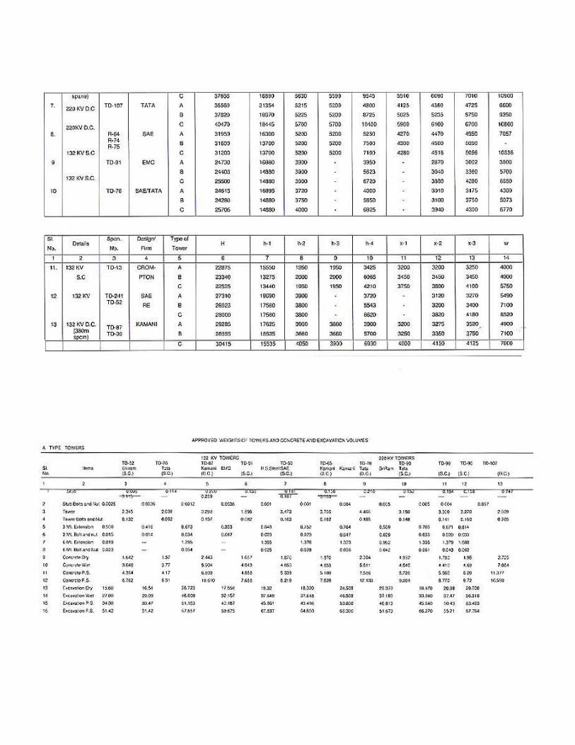
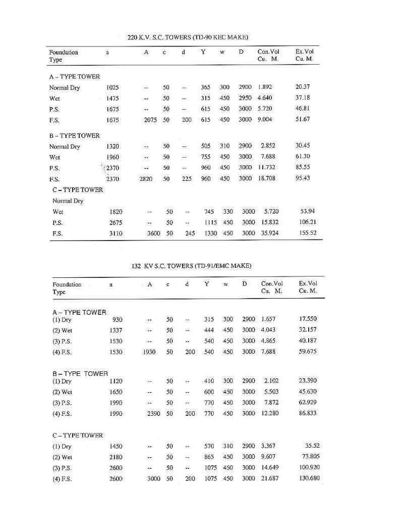
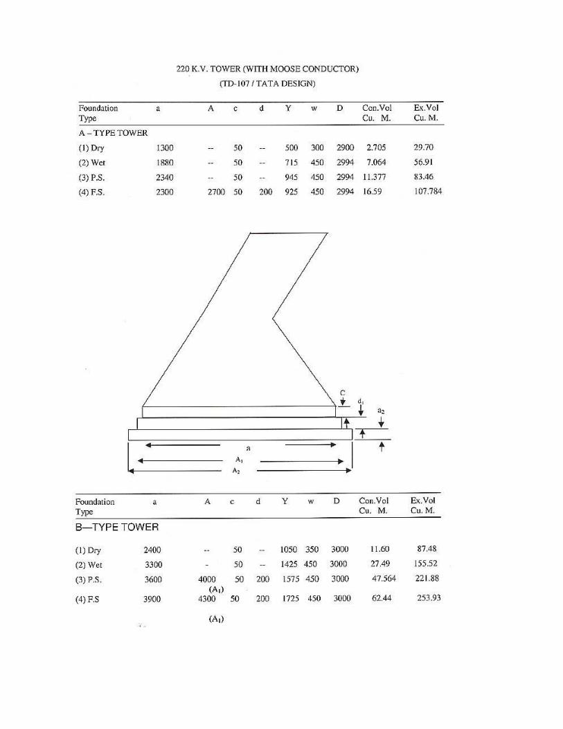
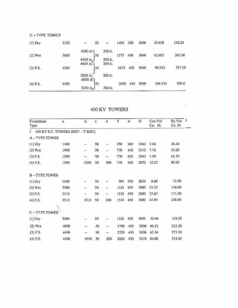
Organization has clearly defined Aims and Objectives which are as under :- � APPROVED WEIGHTS OF TOWERS AND CONCRETE AND
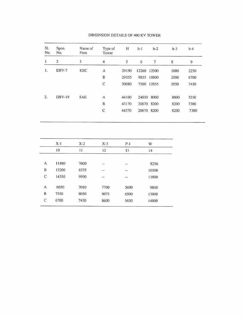
EXCAVATION VOLUMES � CLEARANCES ( EXTRACT FROM MANUL OF ELECTRICITY) � DIMENSION DETAILS OF 132 KV , 220 KV TOWERS � DIMENSION DETAILS OF 400 KV TOWERS � EXTRACTS FROM THE INDIAN TELEGRAPH ACT 1885 RELEVANT TO
POWER LINE � FOUNDATION DETAILS OF LINES � ELECTRICAL ENGINEERING
Norms and Refrence for Operators and Projects Divisions 1. Provisions of Indian Telegraph Act 1885 relevant to Power Lines 2. Clearances from Power Lines (Extract from Manual of Electricity) 3. Useful Technical Data & Information for day to day working 4. Dimension details of 400kv & 132kv Towers 5. Approved weight of Towers & Concrete & Excavation Volumes. 6. Foundation details of Lines

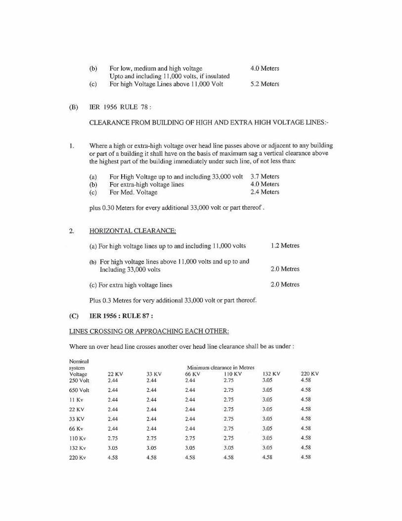
CLEARANCES (EXTRACT FROM MANUAL OF ELECTRICITY LAWS)
1. BUILDING:
(a) Where a high or extra high voltage over head line passes above or adjacent to any building or part of a building, it shall have on the basis of maximum sag, a vertical clearance above the highest part of the building immediately under such line, of not less than :
(a) for high voltage line upto and including. 33 KV 3.658 mtrs. (12 ft.) } (b) for extra high voltage lines 3.685 mtrs. (12 ft.) plus 0.305 mtrs. (1 ft.) for every additional 33 KV or part thereof. (b) The horizontal clearance between the nearest conductor and any part of such building shall on the basis of maximum deflection due to wind pressure, be not less than : (a) for high voltage line upto and including 11 KV 1.219 mtrs. (4ft.) (b) for high voltage line above 11 KV and upto and including 33 KV 1.829 mtrs. (6ft.) (c) for extra high voltage line 1.829 mtrs. (6 ft.) plus 0:305 mtrs, (1 ft.) for every additional 33 KV or part thereof. 2. CLEARANCE ABOVE GROUNDS: (Clause 77 of Indian Electricity Rules) m. m. 33 KV 5100 66 KV 5490 132 KV 6100 220 KV 7015 400 KV 8840 3. CLEARANCE OVER RIVERS : (Above maximum flood level) Rivers not Navigable 3050 mm above HFL. Rivers Navigable Suitable clearance in maximum water level condition, above the tallest mast, in consultation with Navigational authotities concerned. 4. CLEARANCE OVER PTCC LINE m.m 66 KV 2440 132 KV 2745 220 KV 3050 400 KV 4880

5. MINIMUM CLEARANCE BETWEEN POWER LINES : Nominal System Voltage of line to be crossed : KV 11 33 66 132 220 400 11 2.44 2.44 2.44 3.05 4.58 6.10 33 2.44 2.44 3.05 4.58 6.60 66 2.44 3.05 4.58 6.10 132 3.05 4.58 6.10
220 4.58 6.10 400 6.10 Higher voltage line normally be kept over lower voltage line. 6. As per 1SS 162—1961 minimum electrical clearance from live part to earth and safety clearance in case of different voltage must be kept as follows :
VOLTAGE ELECTRICAL CLEARANCE (mm) SAFETY CLEARANCE IN
Phase-Earth / Phase-Phase SIS (mm)
KV 33 381 432 2740 66 658 786 3050 132 1127 1473 3810 220 2082 2388 4570 4000 350 4000 6100 7. CLEARANCE FROM RAILWAY TRACKS : (As per Regulation for Electrical Crossing of Railway Tracks 1963) The relevant provisions for the crossings of Railway .Tracks by the power lines are as under: The minimum height above rail level of the lowest portion of any conductor under conditions of maximum sag are as follows in accordance with the Regulations for Electrical Crossings of Railway Tracks, 1963 :

(i) FOR UNELECTRIFIED TRACKS OR TRACKS ELECTRIFIED ON 1500 VOLTS D. C.
Broad Gauge Metar and Narrow Gauge Inside Outside Inside station
Outside station station limits station limits limits (mm)
limits (mm) (mm) (mm) 66 KV 10,300 7,900 9,100 6,700 13KV 10,0 8,500 9,800 7,300 220 KV 11,200 8,800 1 0,COO 7,600 440 KV* 13,600 11,200 12,400 10,000
(ii) TRACKS ELECTRIFIEDON 25 K.V A.C For Broad, Meter and Narrow Gauges Inside Outside Station station limits limits (mm) (mm) 66 KV 1 3,000 11,000 132 KV 1 4,000 1 2,000 220 KV 1 5,300 1 3,300 440 KV* 1 6,300 14,300 * Tentatively assumed. No conductor of an extra high voltage overhead line crossing a tramway or trolley bus ussing trolley wires should have a clearance less than 3050 mrr. above the trolley line. The Provisions of the above Regulations must be kept in mind while carrying out the patrolling of Transmission lines. Any deviation noticed should be reported / attended on top-priority. 8. PROVISIONS OF PTCC : The requisite information as per the questionaire of PTCC proforma have to be taken care of during patrolling / checking of the line. The copy of the above proforma is also enclosed in the manual at Annexure XVIII An abstract from the "Model Code for Safe Operation and Maintenance of Transmission and Distribution System" as published by the Ministry of Irrigation and power, Central Electricity Board vide No. PMIP-27 / 2000—1979 (DSK II) is also enclosed herewith for general guidance at Annexure XV.
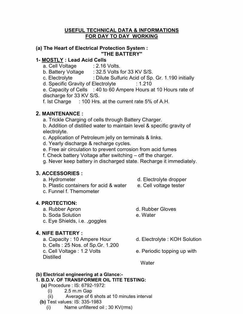
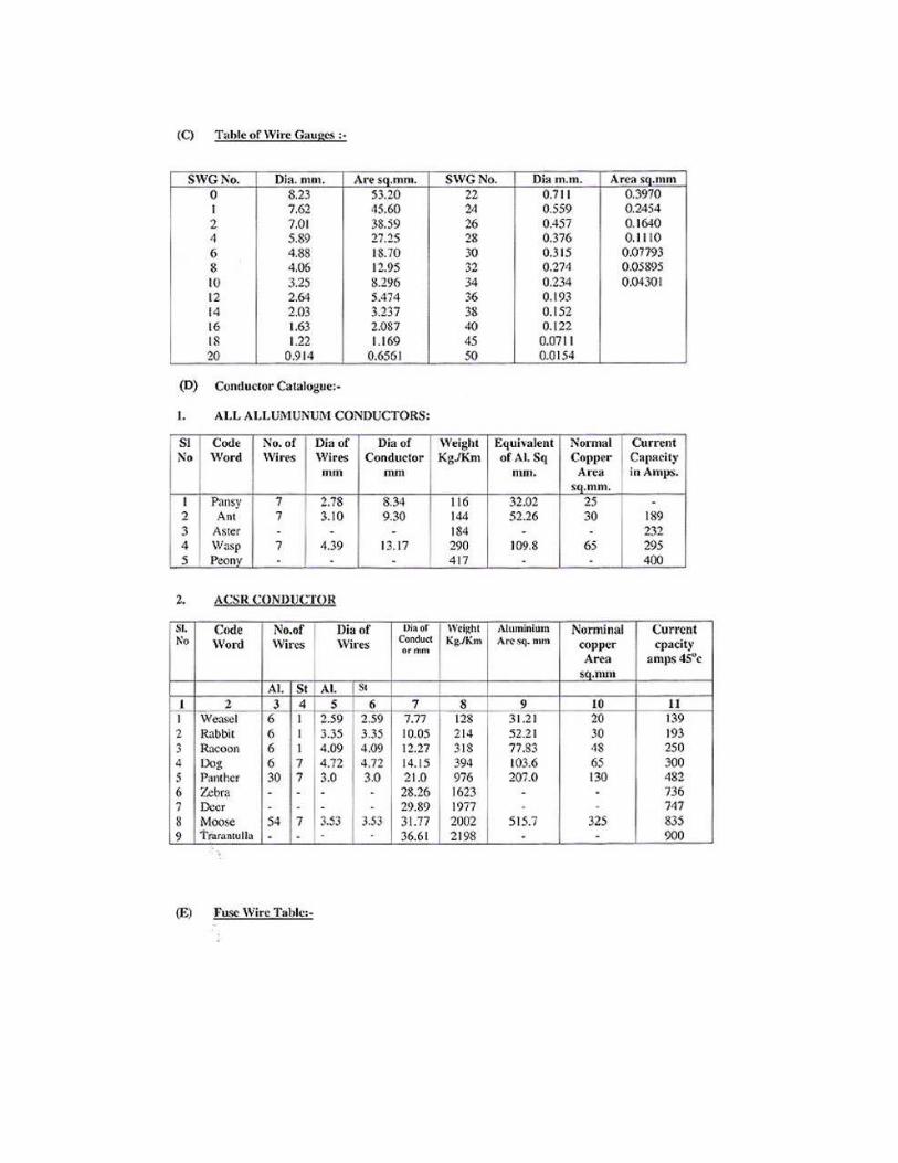
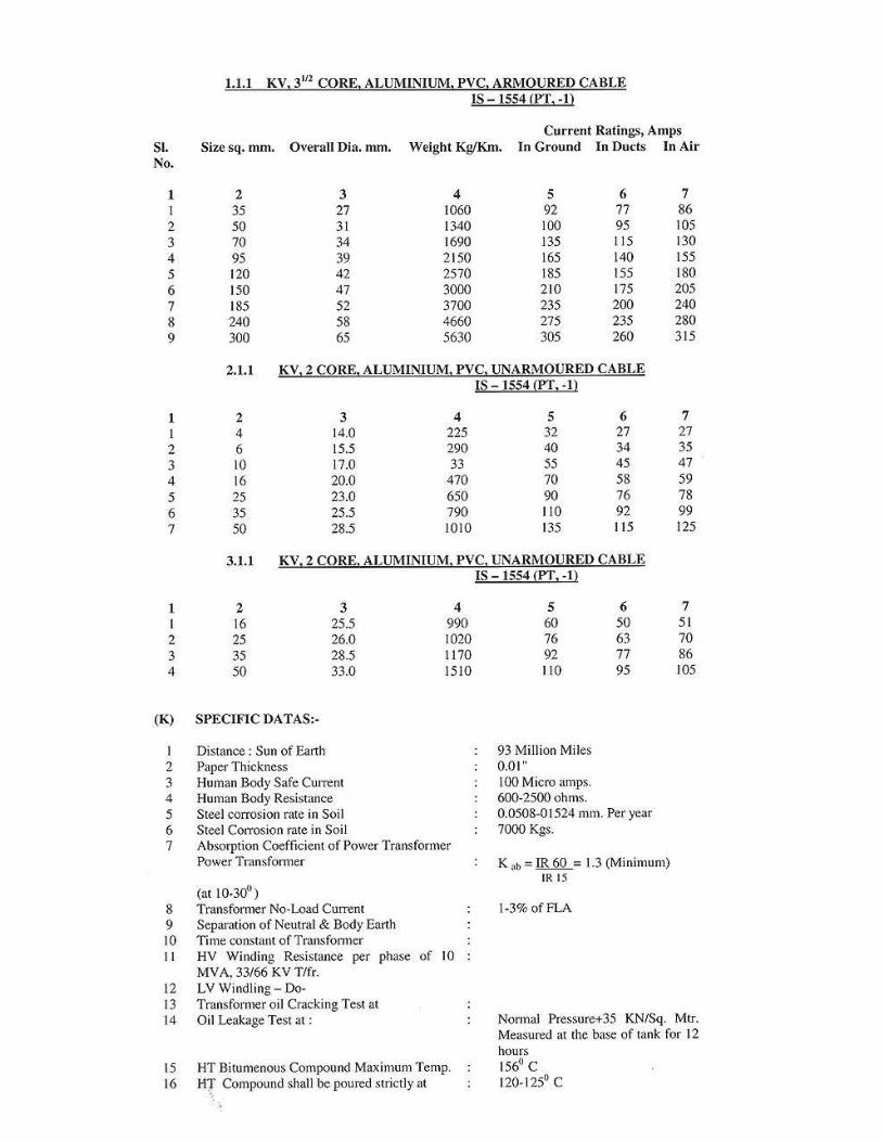
USEFUL TECHNICAL DATA & INFORMATIONS FOR DAY TO DAY WORKING
(a) The Heart of Electrical Protection System :
"THE BATTERY" 1- MOSTLY : Lead Acid Cells
a. Cell Voltage : 2.16 Volts. b. Battery Voltage : 32.5 Volts for 33 KV S/S. c. Electrolyte : Dilute Sulfuric Acid of Sp. Gr. 1.190 initially d. Specific Gravity of Electrolyte : 1.210 e. Capacity of Cells : 40 to 60 Ampere Hours at 10 Hours rate of discharge for 33 KV S/S.
f. Ist Charge : 100 Hrs. at the current rate 5% of A.H.
2. MAINTENANCE : a. Trickle Charging of cells through Battery Charger. b. Addition of distilled water to maintain level & specific gravity of electrolyte. c. Application of Petroleum jelly on terminals & links. d. Yearly discharge & recharge cycles. e. Free air circulation to prevent corrosion from acid fumes f. Check battery Voltage after switching – off the charger. g. Never keep battery in discharged state. Recharge it immediately.
3. ACCESSORIES : a. Hydrometer d. Electrolyte dropper b. Plastic containers for acid & water e. Cell voltage tester c. Funnel f. Themometer
4. PROTECTION: a. Rubber Apron d. Rubber Gloves b. Soda Solution e. Water c. Eye Shields, i.e. ,goggles
4. NIFE BATTERY : a. Capacity : 10 Ampere Hour d. Electrolyte : KOH Solution b. Cells : 25 Nos. of Sp.Gr. 1.200 c. Cell Voltage : 1.2 Volts e. Periodic topping up with Distilled Water
(b) Electrical engineering at a Glance:- 1. B.D.V. OF TRANSFORMER OIL TITE TESTING: (a) Procedure : IS: 6792-1972: (i) 2.5 m.m Gap (ii) Average of 6 shots at 10 minutes interval (b) Test values: IS: 335-1983 (i) Name unfiltered oil ; 30 KV(rms)
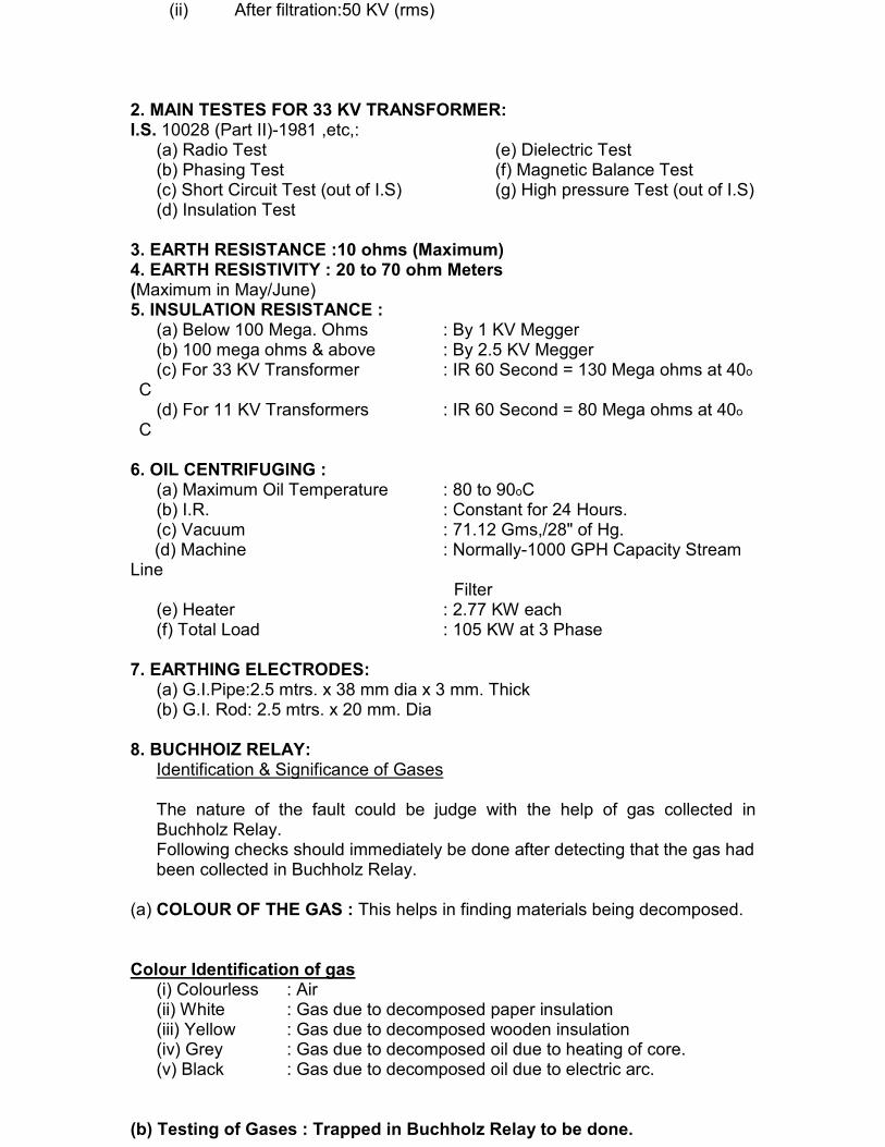
(ii) After filtration:50 KV (rms) 2. MAIN TESTES FOR 33 KV TRANSFORMER: I.S. 10028 (Part II)-1981 ,etc,:
(a) Radio Test (e) Dielectric Test (b) Phasing Test (f) Magnetic Balance Test (c) Short Circuit Test (out of I.S) (g) High pressure Test (out of I.S) (d) Insulation Test
3. EARTH RESISTANCE :10 ohms (Maximum) 4. EARTH RESISTIVITY : 20 to 70 ohm Meters (Maximum in May/June) 5. INSULATION RESISTANCE :
(a) Below 100 Mega. Ohms : By 1 KV Megger (b) 100 mega ohms & above : By 2.5 KV Megger (c) For 33 KV Transformer : IR 60 Second = 130 Mega ohms at 40o
C (d) For 11 KV Transformers : IR 60 Second = 80 Mega ohms at 40o
C
6. OIL CENTRIFUGING : (a) Maximum Oil Temperature : 80 to 90oC (b) I.R. : Constant for 24 Hours. (c) Vacuum : 71.12 Gms,/28" of Hg.
(d) Machine : Normally-1000 GPH Capacity Stream Line Filter
(e) Heater : 2.77 KW each (f) Total Load : 105 KW at 3 Phase
7. EARTHING ELECTRODES: (a) G.I.Pipe:2.5 mtrs. x 38 mm dia x 3 mm. Thick (b) G.I. Rod: 2.5 mtrs. x 20 mm. Dia
8. BUCHHOIZ RELAY: Identification & Significance of Gases The nature of the fault could be judge with the help of gas collected in Buchholz Relay. Following checks should immediately be done after detecting that the gas had been collected in Buchholz Relay.
(a) COLOUR OF THE GAS : This helps in finding materials being decomposed. Colour Identification of gas
(i) Colourless : Air (ii) White : Gas due to decomposed paper insulation (iii) Yellow : Gas due to decomposed wooden insulation (iv) Grey : Gas due to decomposed oil due to heating of core. (v) Black : Gas due to decomposed oil due to electric arc.
(b) Testing of Gases : Trapped in Buchholz Relay to be done.

COMBUSTIBILITY :
A small quantity of gas may be drawn off through top pet cock of the relay by syringe or in a baloon fitted with nozzle or tube and flame tested. About 2 to 5 c.c of gas is expelled into a flame. If the flame brightened, the gas in combustible. Incombustible gas indicates decomposed in insulation & oil vapour
9. SILICA –GEL BREATHER :
(a) Oil Seal : Transformer Oil to be filled-up the marked level. (b) Air Passage : The bottom hole shall be Clear. (c) Silica-gel : Of dark blue colour.
If it is pinkish, replace or reactivate at once. It should not be in power form.
10. PREVENTION OF DISTRIBUTION TRANSFORMERS FROM DAMAGE :
(a) Testing, checking & maintenance at regular intervals. (b) Testing of body & neutral earthings & their maintenance strictly. (c) Only single core L.T. cables to be used from. Transformer to Pillar box and from there to the distribution mains.
(d) L.T. Line Spacers should be provided on L.T. MAINS. (e) The Transformer terminals shall be provided with extensions connectors for
terminating the cables, to prevent damage to studs. (f) Similarly, terminals of Pillar Boxes also shall be provided with extension
connectors. (g) Maximum loading on a transformer shall be 80 %. (h) H.T. Side protection shall be provided by an O.C.B. or at least through a D.O. Fuse Set.
(i) Outgoing load shall not be more than 150 Amp. On any circuit.