manual bt15 - jetter · manual bt15 operator panel with ... 4.7 siemens s5 115u .. 155u via sas525...
TRANSCRIPT

Jetter AG Gräterstr. 2 D-71642 Ludwigsburg Tel: 0 71 41 / 25 50-0 Subject to alterations, errors except Fax: 0 71 41 / 25 50-5 66 Internet: http://www.jetter.de Art.Nr. 60866606
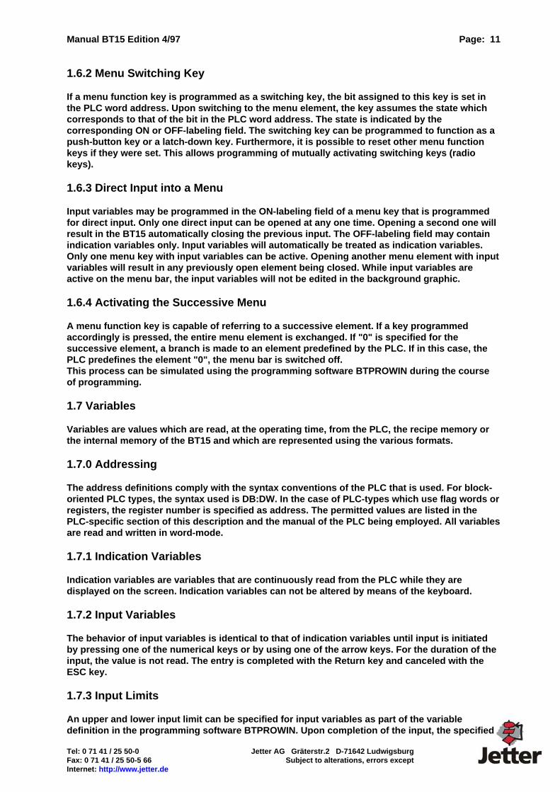
MANUAL BT15
Operator Panel with Graphics Capability for Efficient Machine Operator Control and Monitoring: • PLC offloading: Programmable Application Interface (PAI),
menu memory, recipe memory, real-time clock, password protection • Connection for printer, scanner, disk drive, card reader,
host computer, etc. through reloadable drivers • Language selection for CE-compatible, worldwide use,
CE mark of conformity, tested to IEC, VDE and EN standards • Fault diagnosis via bit field evaluation, 4 priorities: alarm, fault, warning, note
Programmable acknowledgment behavior, import of fault message texts from ASCII files • Full-graphics display, any combination of texts and graphics
scaling of graphical and numerical variables • 26 freely programmable function keys, labeling through slide-in identification strips
26 programmable LEDs in function keys • Communication protocols for all major PLC products Integrated PG-MUX for direct connection to programming unit interface of PLC • Field bus interface modules for CAN, Suconet K1, InterBus-S, Profibus-DP Gateway for Modbus+, additional protocols on request
0
9GHI
4JKL
5MNO
7ABC
8DEF
.+/-
6PQR
1STU
2VWX
3YZ-
ESC
BT 15
Fault Messages:M: 0007 S: 24.2.95 15.12 R: 24.95 15.20 Duration: 00h 8min
Emergency Stop active**** End of LIST
Page: 2 Manual BT15 Edition 4/97
Jetter AG Gräterstr.2 D-71642 Ludwigsburg Tel: 0 71 41 / 25 50-0 Subject to alterations, errors except Fax: 0 71 41 / 25 50-5 66 Internet: http://www.jetter.de
Performance Specifications Casing Front dimensions 240 mm x 168 mm
Panel cut-out 220 mm x 148 mm
Mounting depth 50 mm
Protection class IP 65, on front after mounting
Connection Power supply 24 V = (18 ... 32 V)
Current consumption 300 mA typ.
Interference immunity IEC 801-2, 8 kV air discharge
IEC 801-4 / IEC 801-5, class 4
Display LCD mono STN transflective green /
yellow
LED (or CFL) background lighting
Resolution 240 x 128 pixels
Active area 64 mm x 120 mm
Keyboard 57 membrane keys, embossed with tactile
feedback
26 of these keys with LED
Memory Project memory 384 kByte Flash
Event / recipe memory 90 kByte RAM (option)
Clock (RTC) +/- 50 ppm (option)
Data buffering for RTC and event memory, minimum. 4 weeks battery buffering
Interfaces COM 1 RS 232 for connection to PC
COM 2 RS 422 / RS 485 / RS 232 / 20 mA
interface design depends on PLC
Field buses CAN, Suconet K1, Profibus-DP
InterBus-S, Modbus+
Ambient temperature:
Storage -20 ... +60° C (option -30 ... +80° C)
Operation 0 ... +45° C (option -20 ... +60° C)
Manual BT15 Edition 4/97 Page: 3
Tel: 0 71 41 / 25 50-0 Jetter AG Gräterstr.2 D-71642 Ludwigsburg Fax: 0 71 41 / 25 50-5 66 Subject to alterations, errors except Internet: http://www.jetter.de
MANUAL BT15 .......................................................................................................................................... 1
Performance Specifications ................................................................................................................ 2 1. General Organization........................................................................................................................ 6
1.0 Display Areas............................................................................................................................... 7 1.0.0 Keys ....................................................................................................................................... 8
1.0.0.0 Input Keyboard............................................................................................................... 8 1.0.0.1 Menu Function Keys...................................................................................................... 8 1.0.0.2 Function Keys with LEDs.............................................................................................. 8 1.0.0.3 Radio Groups ................................................................................................................. 8
1.1 Texts/ Language Selection......................................................................................................... 8 1.1.0 System Messages (Texts).................................................................................................... 8 1.1.1 Process Messages ............................................................................................................... 9 1.1.2 Fault Messages (Texts) ........................................................................................................ 9 1.1.3 Symbol Variables / Object Variable Lists.......................................................................... 9 1.1.4 Recipe Memory ..................................................................................................................... 9
1.2 Fonts............................................................................................................................................. 9 1.3 Bitmaps ........................................................................................................................................ 9 1.4 Background Graphics............................................................................................................... 10 1.5 Message Windows .................................................................................................................... 10
1.5.1 Statical Message Windows................................................................................................ 10 1.5.2 PLC-Dependent Message Windows ................................................................................. 10
1.6 Menu Elements .......................................................................................................................... 10 1.6.0 Access Level, PLC-Address.............................................................................................. 10 1.6.1 On/Off - Labeling Field ....................................................................................................... 10 1.6.2 Menu Switching Key........................................................................................................... 11 1.6.3 Direct Input into a Menu..................................................................................................... 11 1.6.4 Activating the Successive Menu....................................................................................... 11
1.7 Variables .................................................................................................................................... 11 1.7.0 Addressing .......................................................................................................................... 11 1.7.1 Indication Variables............................................................................................................ 11 1.7.2 Input Variables .................................................................................................................... 11 1.7.3 Input Limits ......................................................................................................................... 11 1.7.4 Variable Formats................................................................................................................. 13
1.7.4.1 Variable Format ASC ................................................................................................... 13 1.7.4.2 Variable Format BCD ................................................................................................... 13 1.7.4.3 Variable Format BCDL................................................................................................. 13 1.7.4.4 Variable Format BIN..................................................................................................... 13 1.7.4.5 Variable Format FLS .................................................................................................... 13 1.7.4.6 Variable Format HEX ................................................................................................... 13 1.7.4.7 Variable Format INT ..................................................................................................... 13 1.7.4.8 Variable Format INTL................................................................................................... 14 1.7.4.9 Variable Format KT (Siemens S5 only)...................................................................... 14 1.7.4.10 Variable Format SINT (scaled integer)..................................................................... 14 1.7.4.11 Variable Format SUNS (scaled unsigned) ............................................................... 14 1.7.4.12 Variable Format SYM................................................................................................. 14 1.7.4.13 Variable Format UNS ................................................................................................. 14 1.7.4.14 Variable Format BLK (Blink Variable) ...................................................................... 15
1.8 Recipe Variables........................................................................................................................ 15 2. Connection to the PLC ................................................................................................................... 16
2.0 PLC Drivers................................................................................................................................ 16 2.1 WR_PLC ..................................................................................................................................... 17 2.2 RD_PLC ...................................................................................................................................... 18 2.3 Handshake Procedure during Data Transfer.......................................................................... 20 2.4 Restart initiated by BT15 .......................................................................................................... 20 2.5 Synchronization when a Restart is Initiated by the PLC....................................................... 20 2.6 Start-up Element Menu ............................................................................................................. 20 2.7 Variables / Variable Optimization ............................................................................................ 20 2.8 Recipe Transfer ......................................................................................................................... 21
Page: 4 Manual BT15 Edition 4/97
Jetter AG Gräterstr.2 D-71642 Ludwigsburg Tel: 0 71 41 / 25 50-0 Subject to alterations, errors except Fax: 0 71 41 / 25 50-5 66 Internet: http://www.jetter.de
2.9 Reading Clock from PLC and Setting Clock .......................................................................... 21 2.10 Transmitting Clock to PLC at Cyclic Intervals ..................................................................... 21
3. Programming Software .................................................................................................................. 22 3.1 Installation of the Programming Software.............................................................................. 22 3.2 Starting the Programming Software........................................................................................ 23
3.2.1 Editing Project .................................................................................................................... 23 3.2.1.1 System Set-Up.............................................................................................................. 23
3.2.1.1.1 Device Set-Up ........................................................................................................ 23 3.2.1.1.1.2 Fault Diagnosis ............................................................................................... 23 3.2.1.1.1.3 Recipes ............................................................................................................ 23 3.2.1.1.1.4 Blinking Intervals............................................................................................ 24
3.2.1.1.2 Keyboard Set-Up ................................................................................................... 24 3.2.1.1.3 Driver Set-Up.......................................................................................................... 24
3.2.1.1.3.1 Network Address: ........................................................................................... 24 3.2.1.1.3.2 RD_PLC: .......................................................................................................... 24 3.2.1.1.3.3 WR_PLC:.......................................................................................................... 24 3.2.1.1.3.4 Variable Address Min, Max.: .......................................................................... 24
3.2.1.2 Variable Definition........................................................................................................ 24 3.2.1.2.1 Editing Variables ................................................................................................... 25
3.2.1.3 Editing Background Graphics .................................................................................... 25 3.2.1.4 Message Editor............................................................................................................. 25 3.2.1.5 Editing Process Messages.......................................................................................... 25 3.2.1.6 Editing System Messages........................................................................................... 25 3.2.1.7 Editing Fault Messages ............................................................................................... 25 3.2.1.8 Editing the Menu Structure ......................................................................................... 26 3.2.1.9 Editing Object Variables.............................................................................................. 26
4. Connecting to the PLC ................................................................................................................... 27 4.1 3964R.......................................................................................................................................... 27 4.2 AEG - Modicon A120 / A250 (KS-Functions) .......................................................................... 29 4.3 Allen-Bradley DF1 ..................................................................................................................... 31 4.4 MODBUS RTU............................................................................................................................ 33 4.5 MODBUS+ via Gateway ............................................................................................................ 35 4.6 Siemens S5 via L1..................................................................................................................... 37 4.7 Siemens S5 115U .. 155U via SAS525 ..................................................................................... 36 4.8 Mitsubishi FX-Series................................................................................................................. 48 4.9 Klöckner - Moeller Suconet K1 ................................................................................................ 48 4.10 InterBus-S ................................................................................................................................ 49 4.11 Profibus DP.............................................................................................................................. 51
5. System Messages........................................................................................................................... 52 6. Internal Variables ............................................................................................................................ 55 7. PROGRAMMABLE APPLICATION INTERFACE PAI V1.0 ........................................................ 56
7.1. Memory Allocation between BT and PAI ............................................................................... 56 7.1.1 BT Area ................................................................................................................................ 56 7.1.2 PAI Area............................................................................................................................... 57 7.1.3 Array Memory Areas .......................................................................................................... 57
7.1.3.1 Access to Arrays.......................................................................................................... 57 7.2. Communication with the PLC ................................................................................................. 58
7.2.1 Cyclic Data Exchange with the PLC ................................................................................. 58 7.2.2 Reading and Writing Variables.......................................................................................... 58 7.2.3 Program-Controlled Reading and Writing of Data (PAI)................................................. 58
7.3 PAI Program............................................................................................................................... 58 7.3.1 Language Elements............................................................................................................ 59
7.4 Structure of a PAI Program...................................................................................................... 60 7.5. Commands................................................................................................................................ 60
7.5.1 "LoadWord", "LW" ............................................................................................................. 60 7.5.2 "IFx" ..................................................................................................................................... 60 7.5.3 "INC" .................................................................................................................................... 61 7.5.4 "DEC"................................................................................................................................... 61 7.5.5 "AND"................................................................................................................................... 61
Manual BT15 Edition 4/97 Page: 5
Tel: 0 71 41 / 25 50-0 Jetter AG Gräterstr.2 D-71642 Ludwigsburg Fax: 0 71 41 / 25 50-5 66 Subject to alterations, errors except Internet: http://www.jetter.de
7.5.6 "OR" ..................................................................................................................................... 61 7.5.7 "SUB"................................................................................................................................... 61 7.5.8 "ADD"................................................................................................................................... 62 7.5.9 "LoadBit","LB".................................................................................................................... 62 7.5.10 "SetBit","SB"..................................................................................................................... 62 7.5.11 "ResetBit", "RB" ............................................................................................................... 62 7.5.12 "IFSET" .............................................................................................................................. 62 7.5.13 "IFRESET" ......................................................................................................................... 62 7.5.14 "IFPLU" .............................................................................................................................. 62 7.5.15 "IFPLD" .............................................................................................................................. 63 7.5.20 "RETURN","RET".............................................................................................................. 63 7.5.21 "GOTO","GO".................................................................................................................... 63 7.5.22 "COPY" .............................................................................................................................. 63 7.5.23 "DEF" ................................................................................................................................. 63 7.5.24 "PLCTR" ............................................................................................................................ 63 7.5.25 "CANTR"............................................................................................................................ 63
8. PAI Compiler ................................................................................................................................... 64 8.1 Download and Integration ........................................................................................................ 64
9. BT / PAI Addresses......................................................................................................................... 65

Page: 6 Manual BT15 Edition 4/97
Jetter AG Gräterstr.2 D-71642 Ludwigsburg Tel: 0 71 41 / 25 50-0 Subject to alterations, errors except Fax: 0 71 41 / 25 50-5 66 Internet: http://www.jetter.de
1. General Organization
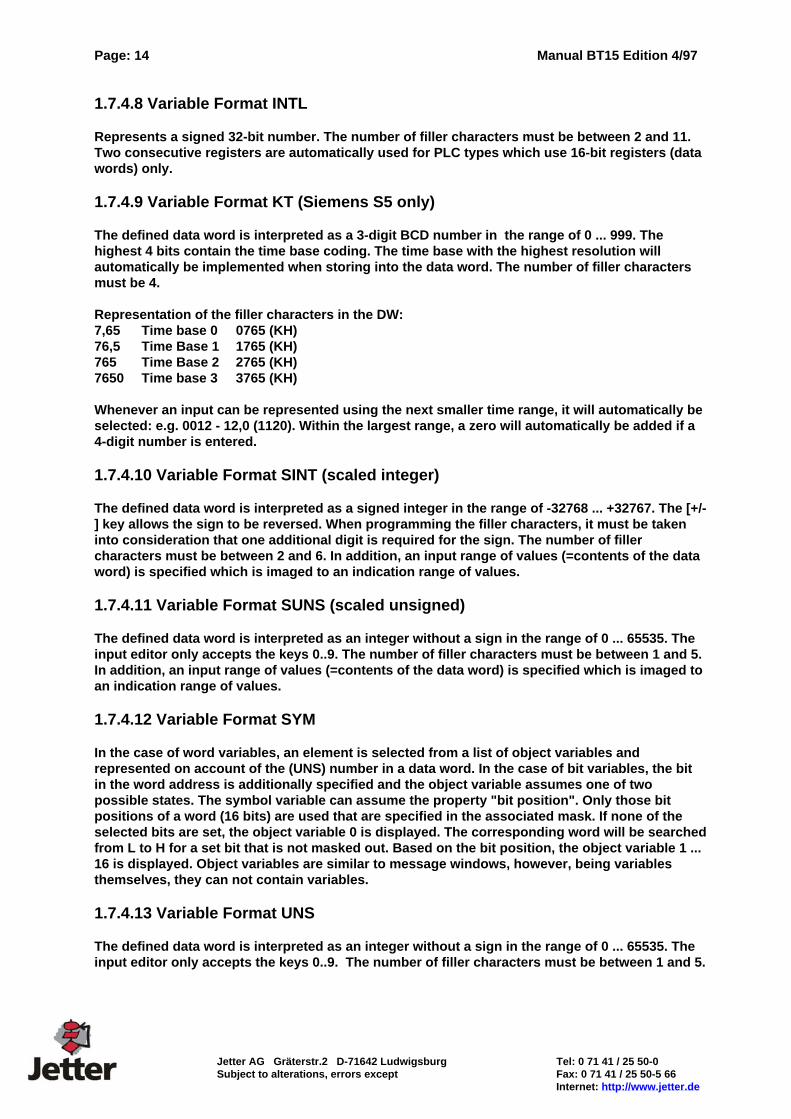
With the BT15, we offer an operator panel for complete machine operator control. Aluminum front panels and zinc-coated plate steel casings provide for interference-free employment even in harsh industrial environments. On account of the sealed front mounting of the BT15, an IP65 degree of protection is obtained. Inserting the labeling strips from the sealed inner side of the device ensures that this degree of protection is maintained. Extensive tests have shown that the BT15 is both reliable and suitable for use in industrial applications. Mechanical stability, EMC, temperature and climatic tests ensure that the high level of quality of the operator panels is maintained. The monochrome LCD display features CFL background lighting offering high readability from various directions. A resolution of 240 x 128 pixels allows for a spacious display of texts and graphics. Exchangeable interface modules allow ease of adaptation to various interface standards and various bus systems. The protocol drivers can be loaded using the programming software. It is not necessary to order the BT15 in a protocol-specific manner. This manual provides a detailed description of the various elements of the BT15.
BT15
DISPLAY240 * 128black-whitefor ambienttemperatures 0..45 C
Keyboard/ LED
Clock/Battery OptionPower reserve/Minimum of 4 weeksdata buffering of RAM
INTERFACEto peripherals (PC)
FIRMWARE
Menu structureAccess levelsSymbol variablesLevel indicatorvariablesNumerical variablesMessage WindowsGraphics managem.Recipe managementFault diagnosisDriver to PLCDriver for field bus
ROM (Flash)
Graphics (Bitmap)FontsMessage texts
System messagesProcess messagesFault messages
Message definitionsVariable definitionsKeyboard logicMenu structureExtended programminglanguage PAIPLc driver
RAMFault diagnostic memoryRecipe memoryVariablesWorking memory for PAIData logger
Optional P A I PAI: rogrammable pplication nterfaceSequential program to relieve PLC of operator control and monitoring tasks.
Physical interface for or connectionPLC field bus
Manual BT15 Edition 4/97 Page: 7
Tel: 0 71 41 / 25 50-0 Jetter AG Gräterstr.2 D-71642 Ludwigsburg Fax: 0 71 41 / 25 50-5 66 Subject to alterations, errors except Internet: http://www.jetter.de
1.0 Display Areas The display area of the BT15 can be divided into three basic, independent areas: 256 background graphics up to 1000 menu elements for the menu structure Lists for fault diagnosis Message windows for system messages
Background graphics include Graphics (Bitmap) Message windows Level indicator variables Blink variables Symbol variables
Menu elements include Texts Graphics (Bitmap) Numerical variables of the described formats Symbol variables
Lists for fault diagnosis include Fault message texts Time information on start of fault Time information on end of fault Time information on duration of fault
Message windows include Message texts Numerical variables of the described formats Symbol variables (object variables) Graphics (Bitmap)
Message windows for system messages include System messages appear on the display only, when errors are detected by the operating
system of the BT15. For a description of the meaning of each message see the section "System Messages".
This simple structure should be memorized carefully in order to maintain an overview of the wide range of different configuration options.
Page: 8 Manual BT15 Edition 4/97
Jetter AG Gräterstr.2 D-71642 Ludwigsburg Tel: 0 71 41 / 25 50-0 Subject to alterations, errors except Fax: 0 71 41 / 25 50-5 66 Internet: http://www.jetter.de
1.0.0 Keys The BT15 is provided with a high-quality membrane keyboard comprising a total of 57 large, embossed keys with excellent tactile feedback. The keyboard is divided into 3 groups: input keyboard (numerical and cursor keys), 5 menu function keys and 26 freely assignable function keys with LEDs. 1.0.0.0 Input Keyboard The input keyboard allows input of values into variables. In addition, every push of a button is transferred to the PLC as a code (see allocation in WR_PLC). 1.0.0.1 Menu Function Keys The function of the menu function keys (6 keys located to the left of the screen) is determined in conjunction with the menu elements. In addition, every push of a key is transferred to the PLC in bit mode. 1.0.0.2 Function Keys with LEDs The BT15 comprises 26 function keys (S1 .. S26). Each of these function keys is provided with a LED and allows for labeling. Each key can be programmed to function as a push-button key or as a latch-down key. These keys are transferred to the PLC individually (in bit mode) and are thus capable of directly activating functions, independently of the menus. The LED in each function key can either be allocated to a bit in the PLC or indicate the state of the (latch-down) key. A slide-in labeling strip which can be inserted from the inner side of the device allows convenient and clear labeling of the keys while maintaining the high degree of protection (IP65). 1.0.0.3 Radio Groups The 26 function keys (S1 .. S26) can be combined to radio groups. Radio keys are keys, that mutually activate. A radio group is identified by being assigned the same group number in the programming software BTPROWIN. 1.1 Texts/ Language Selection The text items in the BT15 are divided into various groups: system texts, process texts, fault message texts and text (symbol) variables. The programming software BTPROWIN is capable of managing up to 10 languages. During the download to the BT15, it is possible to select 2 languages with the first language being the customer language and the second the service language. Since the text input is also graphic-oriented, the use of symbols and various character sets is possible. 1.1.0 System Messages (Texts) System messages are displayed or added to the diagnostic memory by the BT15 as a result of specific internal operating states. Variables are inserted into some of the messages. The underline character (_) is used as a filler character. The number of filler characters for compilations is also precisely specified. If no text has been programmed, the following text is displayed "Systext-No. xxx Error 12". Recommendations for texts and their meanings are listed in the appendix.
Manual BT15 Edition 4/97 Page: 9
Tel: 0 71 41 / 25 50-0 Jetter AG Gräterstr.2 D-71642 Ludwigsburg Fax: 0 71 41 / 25 50-5 66 Subject to alterations, errors except Internet: http://www.jetter.de
1.1.1 Process Messages Process messages are messages that are used for representation purposes in message definitions. Messages may contain text items, graphics and variables. Up to 1000 process messages can be defined. If a process text is used that has not been programmed, the following message is displayed: "Process Text xxx Error 11". 1.1.2 Fault Messages (Texts) Fault message texts are messages that are added to the diagnostic memory by the fault diagnosis function. The individual messages are allocated to the single bits of the bit field in a specific order of sequence. This allocation is fixed. Message1= bit n.1, message2= bit n.2, message15= bit n.15; message16= bit n+1.0, etc. If a fault message is used that has not been programmed, the following message is displayed: "Fault Text No. xxx Error 13". Up to 1023 fault messages can be programmed. This corresponds to 64 words. 1.1.3 Symbol Variables / Object Variable Lists Depending on a data word or a bit in a data word, it is possible to insert symbols or texts from an object variable list into a message or a background graphics. Up to 256 objects can be defined per object variable list. Up to 100 object variable lists can be created. Similar to message texts, symbol variables are also created in multiple languages. 1.1.4 Recipe Memory Part of the RAM memory can be configured as "recipe memory". The recipe memory is a two-dimensional word-oriented array. The variable I0 is the pointer to the selected recipe. Within the recipe, data are accessed via the internal variables I1 .. In. 1.2 Fonts Two non-proportional fonts, optimized for screen resolutions of 240x128 pixels, are supplied with the programming software BTPROWIN. They are especially suited for representation of small fonts as well as tables where proportional fonts would be disturbing. In addition, we supply the font "Passwortsymbol" (password symbol) to allow concealed input and the font "E/A - Symbol" (I/O - Symbol) which principally allows a graphical representation of binary variables. Any fonts provided by Windows can also be used. Whenever an additional font is used, the new font data are added to the data record during the compilation process. 1.3 Bitmaps Graphic elements must be available on the hard disk as Windows-bitmaps (.bmp). Ensure that the size of the graphics does not exceed 240x128 pixels. Normal graphics use the black and white format while background graphics and graphics with level indicator variables use 16 colors (RGB). The green portion is used for the active area of a level indicator variable.
Page: 10 Manual BT15 Edition 4/97
Jetter AG Gräterstr.2 D-71642 Ludwigsburg Tel: 0 71 41 / 25 50-0 Subject to alterations, errors except Fax: 0 71 41 / 25 50-5 66 Internet: http://www.jetter.de
1.4 Background Graphics The BT15 is capable of displaying up to 256 background graphics. A background graphic may contain one or more graphics. Graphics smaller than 240x128 pixels can be placed at any position on the screen. A background graphic may contain level indicator variables, symbol variables and up to 31 message definitions. 1.5 Message Windows Message definitions are elements which are inserted into a background graphics. A message definition consists of a size (height x width), expressed in pixels, a border (none, normal, bold, double) and a process message. Up to 31 message definitions can be used per background graphic. 1.5.1 Statical Message Windows A statical message definition is only capable of displaying one of the process messages defined during the programming. 1.5.2 PLC-Dependent Message Windows For PLC-dependent message definitions, the process message to be displayed is not defined when the programming is carried out but at the operating time of the PLC. During the course of programming, the address of the PLC is specified from which onwards the number of the process message to be displayed is read. 1.6 Menu Elements Up to 1000 menu elements can be defined. Within each of the menu elements, the 5 function keys are provided with a new labeling and assume a new function. The window size for a key is 120*32 pixels. 1.6.0 Access Level, PLC-Address A word address and an access level, one of 32, is assigned to each menu element. The PLC word address can be accessed in bit-mode provided one or more of the 5 menu function keys are programmed as switching keys. When the menu definition is activated, the contents of the PLC word address is read from the PLC and is written to the PLC upon every modification via the menu function keys. During this time period, no modifications should be made by the PLC as they would be overwritten by the BT15. 1.6.1 On/Off - Labeling Field Every menu function key is assigned at least 1 labeling field within each menu element. For menu function keys which are capable of assuming 2 states (direct input, switching key), the second labeling field is made use of as well. The first labeling field, in the programming software the top labeling field, is visible while the key is “OFF”. The second labeling field is visible if the key is “ON”. The entire menu definition is exchanged, however, if a key is programmed as a menu key, i.e. the second labeling field is never visible. The labeling fields may contain texts, graphics and variables but not message definitions.
Manual BT15 Edition 4/97 Page: 11
Tel: 0 71 41 / 25 50-0 Jetter AG Gräterstr.2 D-71642 Ludwigsburg Fax: 0 71 41 / 25 50-5 66 Subject to alterations, errors except Internet: http://www.jetter.de
1.6.2 Menu Switching Key If a menu function key is programmed as a switching key, the bit assigned to this key is set in the PLC word address. Upon switching to the menu element, the key assumes the state which corresponds to that of the bit in the PLC word address. The state is indicated by the corresponding ON or OFF-labeling field. The switching key can be programmed to function as a push-button key or a latch-down key. Furthermore, it is possible to reset other menu function keys if they were set. This allows programming of mutually activating switching keys (radio keys). 1.6.3 Direct Input into a Menu Input variables may be programmed in the ON-labeling field of a menu key that is programmed for direct input. Only one direct input can be opened at any one time. Opening a second one will result in the BT15 automatically closing the previous input. The OFF-labeling field may contain indication variables only. Input variables will automatically be treated as indication variables. Only one menu key with input variables can be active. Opening another menu element with input variables will result in any previously open element being closed. While input variables are active on the menu bar, the input variables will not be edited in the background graphic. 1.6.4 Activating the Successive Menu A menu function key is capable of referring to a successive element. If a key programmed accordingly is pressed, the entire menu element is exchanged. If "0" is specified for the successive element, a branch is made to an element predefined by the PLC. If in this case, the PLC predefines the element "0", the menu bar is switched off. This process can be simulated using the programming software BTPROWIN during the course of programming. 1.7 Variables Variables are values which are read, at the operating time, from the PLC, the recipe memory or the internal memory of the BT15 and which are represented using the various formats. 1.7.0 Addressing The address definitions comply with the syntax conventions of the PLC that is used. For block-oriented PLC types, the syntax used is DB:DW. In the case of PLC-types which use flag words or registers, the register number is specified as address. The permitted values are listed in the PLC-specific section of this description and the manual of the PLC being employed. All variables are read and written in word-mode. 1.7.1 Indication Variables Indication variables are variables that are continuously read from the PLC while they are displayed on the screen. Indication variables can not be altered by means of the keyboard. 1.7.2 Input Variables The behavior of input variables is identical to that of indication variables until input is initiated by pressing one of the numerical keys or by using one of the arrow keys. For the duration of the input, the value is not read. The entry is completed with the Return key and canceled with the ESC key. 1.7.3 Input Limits An upper and lower input limit can be specified for input variables as part of the variable definition in the programming software BTPROWIN. Upon completion of the input, the specified

Page: 12 Manual BT15 Edition 4/97
Jetter AG Gräterstr.2 D-71642 Ludwigsburg Tel: 0 71 41 / 25 50-0 Subject to alterations, errors except Fax: 0 71 41 / 25 50-5 66 Internet: http://www.jetter.de
value is checked for compliance with the programmed input value ranges and if it is within the limits, is then written to the PLC.
Manual BT15 Edition 4/97 Page: 13
Tel: 0 71 41 / 25 50-0 Jetter AG Gräterstr.2 D-71642 Ludwigsburg Fax: 0 71 41 / 25 50-5 66 Subject to alterations, errors except Internet: http://www.jetter.de
1.7.4 Variable Formats Various formats can be used to display variables on the screen. During the variable definition, the representation format is selected on the display. 1.7.4.1 Variable Format ASC The filler characters are filled with ASCII characters starting with the H byte of the specified address. Only displayable characters (from 20h onwards) are permitted. ASCII variables can also be entered via the keyboard. The keys can be assigned up to four functions (in the same way as the keys on a telephone). 1.7.4.2 Variable Format BCD The defined data word is interpreted as a 4-digit BCD-number in the range of 0 ... 9999. The number of filler characters must be between 1 and 4. If the data word has been predefined by the PLC with nibbles >9, they will be represented by the characters A to F (HEX). 1.7.4.3 Variable Format BCDL The defined data word is interpreted as an 8-digit BCD-number in the range of 0 ... 99999999. The number of filler characters must be between 5 and 8. Two consecutive registers (data words) are always read. If the register has been predefined by the PLC with nibbles >9, they will be represented by the characters A to F (HEX). 1.7.4.4 Variable Format BIN The defined data word is represented as 16 single bits. The number of filler characters must be between 1 and 16. The number of bits displayed corresponds to the number of defined filler characters. The input editor accepts the keys 0 and 1. During the definition, it is possible to define the start-up bit from which onwards the more significant bits are to be displayed. The process of reading from the PLC, however, involves that the entire word is read from the PLC and (if programmed as input variable) also written to the PLC. Any modifications performed by the PLC in the meantime will therefore be overwritten by this process. 1.7.4.5 Variable Format FLS Level indicator variables are graphical variables. The horizontal or vertical expansion of an area varies in accordance with the contents of a data word. The area is read in as a bitmap. The variable is scaled during the definition. In addition to bars, polygons can be represented with angles of >90 degrees (funnels, tanks, rectangles, circles). Level indicator variables are scaled in the direction of movement. 1.7.4.6 Variable Format HEX The defined data word is interpreted as a 4-digit HEX-number in the range of 0 ... FFFF. The number of filler characters must be between 1 and 4. The input editor only accepts the keys 0 ... 9. The characters A ... F are produced by simultaneously pressing the key [SFT] and one of the keys 0 .. 5 (corresponds to A .. F). 1.7.4.7 Variable Format INT The defined data word is interpreted as a signed integer in the range of -32768 ... +32767. The [+/-] key allows the sign to be reversed. When programming the filler characters, it must be taken into consideration that one additional digit is required for the sign. The number of filler characters must be between 2 and 6.
Page: 14 Manual BT15 Edition 4/97
Jetter AG Gräterstr.2 D-71642 Ludwigsburg Tel: 0 71 41 / 25 50-0 Subject to alterations, errors except Fax: 0 71 41 / 25 50-5 66 Internet: http://www.jetter.de
1.7.4.8 Variable Format INTL Represents a signed 32-bit number. The number of filler characters must be between 2 and 11. Two consecutive registers are automatically used for PLC types which use 16-bit registers (data words) only. 1.7.4.9 Variable Format KT (Siemens S5 only) The defined data word is interpreted as a 3-digit BCD number in the range of 0 ... 999. The highest 4 bits contain the time base coding. The time base with the highest resolution will automatically be implemented when storing into the data word. The number of filler characters must be 4. Representation of the filler characters in the DW: 7,65 Time base 0 0765 (KH) 76,5 Time Base 1 1765 (KH) 765 Time Base 2 2765 (KH) 7650 Time base 3 3765 (KH) Whenever an input can be represented using the next smaller time range, it will automatically be selected: e.g. 0012 - 12,0 (1120). Within the largest range, a zero will automatically be added if a 4-digit number is entered. 1.7.4.10 Variable Format SINT (scaled integer) The defined data word is interpreted as a signed integer in the range of -32768 ... +32767. The [+/-] key allows the sign to be reversed. When programming the filler characters, it must be taken into consideration that one additional digit is required for the sign. The number of filler characters must be between 2 and 6. In addition, an input range of values (=contents of the data word) is specified which is imaged to an indication range of values. 1.7.4.11 Variable Format SUNS (scaled unsigned) The defined data word is interpreted as an integer without a sign in the range of 0 ... 65535. The input editor only accepts the keys 0..9. The number of filler characters must be between 1 and 5. In addition, an input range of values (=contents of the data word) is specified which is imaged to an indication range of values. 1.7.4.12 Variable Format SYM In the case of word variables, an element is selected from a list of object variables and represented on account of the (UNS) number in a data word. In the case of bit variables, the bit in the word address is additionally specified and the object variable assumes one of two possible states. The symbol variable can assume the property "bit position". Only those bit positions of a word (16 bits) are used that are specified in the associated mask. If none of the selected bits are set, the object variable 0 is displayed. The corresponding word will be searched from L to H for a set bit that is not masked out. Based on the bit position, the object variable 1 ... 16 is displayed. Object variables are similar to message windows, however, being variables themselves, they can not contain variables. 1.7.4.13 Variable Format UNS The defined data word is interpreted as an integer without a sign in the range of 0 ... 65535. The input editor only accepts the keys 0..9. The number of filler characters must be between 1 and 5.
Manual BT15 Edition 4/97 Page: 15
Tel: 0 71 41 / 25 50-0 Jetter AG Gräterstr.2 D-71642 Ludwigsburg Fax: 0 71 41 / 25 50-5 66 Subject to alterations, errors except Internet: http://www.jetter.de
1.7.4.14 Variable Format BLK (Blink Variable) Rectangular areas can be defined which, depending on a bit address in the PLC, are inverted at the specified blinking frequency. Blinking areas should not be directly above variables. Either the entire area can blink or just the frame around it. The frame type is defined during the programming stage. 1.8 Recipe Variables Recipe variables are accessed via internal variables. The internal variable I1 is the first recipe entry, the internal variable I2 is the second recipe entry, etc. I(max.) is obtained from the programmed number of words / recipes. The recipe number is set in the internal variable I0. Valid values for I0 are 1... maximum number of recipes. Up to 4000 recipes can be defined.
Page: 16 Manual BT15 Edition 4/97
Jetter AG Gräterstr.2 D-71642 Ludwigsburg Tel: 0 71 41 / 25 50-0 Subject to alterations, errors except Fax: 0 71 41 / 25 50-5 66 Internet: http://www.jetter.de
2. Connection to the PLC The physical connection to the PLC varies with the make of the PLC. For a more detailed description see the PLC-specific section. A serial connection via the programming unit interface is used for most PLC makes. In addition, the following "true" bus systems are available: MODBUS+ via external gateway PROFIBUS DP via plug-in type interface card Interbus-S (remote bus) CAN (in preparation) The logical connection to the PLC has been designed in such a way that it is, to a large extent, independent of the bus system and PLC driver. A distinction is made here between three communication areas: 1. Access of variables and PLC-specific message windows to the PLC word address is performed by simply specifying the address in the variable definition or during the definition of the message window. It must only be ensured that the PLC address is a valid address for the connected PLC. 2. Write block and read block (WR_PLC and RD_PLC) without using the optional programming language of the PAI (Programmable Application Interface). Two data blocks are defined here whose starting and end addresses are specified in the programming software (BTPROWIN) under >"System Set-Up" >" Driver Set-Up". The data are read from the PLC at cyclic intervals and are written primarily to the PLC if any changes are made (key actuation). In addition, further data can be exchanged with the PLC in an event-controlled manner if PAI is used. 2.0 PLC Drivers The following PLC drivers are available or are in preparation: AEG Modicon A120/250 (KS-Functions) AEG MICROAKF AEG Modicon 984 (Modbus RTU) AEG Modicon Micro AEG Modicon Modbus+ connectable via external gateway (Modbus+ -> ModbusRTU) Allen-Bradley SLC 5/03, PLC 5/11, PLC 5/20, PLC 5/30, PLC 5/40, PLC 5/60, PLC 5/80 Bosch BUEP 19 / BUEP 19E Klöckner Moeller PS 306 / PS 316 via SucomA Klöckner Moeller PS4-200 / Suconet K1(special plug-in type interface card required in BT15) Mitsubishi Series FX / FX0 Omron Series H, Series CQM Siemens S5 (L1)100U CPU 103 / 90U / 95U / 115U Siemens S5 (SAS)115U / 135U / 155U (SAS525 interface card allows connection of up to 16 devices) Siemens (Profibus DP) (special plug-in type interface card required in BT15). A data handling block for S7-300 is available. Interbus-S digital remote bus station (special plug-in type interface card required in BT15) (additional available on request)
Manual BT15 Edition 4/97 Page: 17
Tel: 0 71 41 / 25 50-0 Jetter AG Gräterstr.2 D-71642 Ludwigsburg Fax: 0 71 41 / 25 50-5 66 Subject to alterations, errors except Internet: http://www.jetter.de
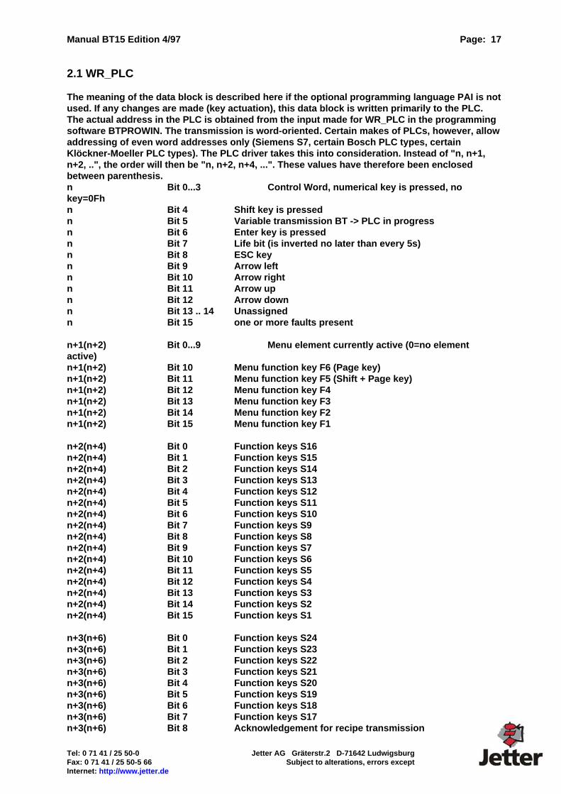
2.1 WR_PLC The meaning of the data block is described here if the optional programming language PAI is not used. If any changes are made (key actuation), this data block is written primarily to the PLC. The actual address in the PLC is obtained from the input made for WR_PLC in the programming software BTPROWIN. The transmission is word-oriented. Certain makes of PLCs, however, allow addressing of even word addresses only (Siemens S7, certain Bosch PLC types, certain Klöckner-Moeller PLC types). The PLC driver takes this into consideration. Instead of "n, n+1, n+2, ..", the order will then be "n, n+2, n+4, ...". These values have therefore been enclosed between parenthesis. n Bit 0...3 Control Word, numerical key is pressed, no key=0Fh n Bit 4 Shift key is pressed n Bit 5 Variable transmission BT -> PLC in progress n Bit 6 Enter key is pressed n Bit 7 Life bit (is inverted no later than every 5s) n Bit 8 ESC key n Bit 9 Arrow left n Bit 10 Arrow right n Bit 11 Arrow up n Bit 12 Arrow down n Bit 13 .. 14 Unassigned n Bit 15 one or more faults present n+1(n+2) Bit 0...9 Menu element currently active (0=no element active) n+1(n+2) Bit 10 Menu function key F6 (Page key) n+1(n+2) Bit 11 Menu function key F5 (Shift + Page key) n+1(n+2) Bit 12 Menu function key F4 n+1(n+2) Bit 13 Menu function key F3 n+1(n+2) Bit 14 Menu function key F2 n+1(n+2) Bit 15 Menu function key F1 n+2(n+4) Bit 0 Function keys S16 n+2(n+4) Bit 1 Function keys S15 n+2(n+4) Bit 2 Function keys S14 n+2(n+4) Bit 3 Function keys S13 n+2(n+4) Bit 4 Function keys S12 n+2(n+4) Bit 5 Function keys S11 n+2(n+4) Bit 6 Function keys S10 n+2(n+4) Bit 7 Function keys S9 n+2(n+4) Bit 8 Function keys S8 n+2(n+4) Bit 9 Function keys S7 n+2(n+4) Bit 10 Function keys S6 n+2(n+4) Bit 11 Function keys S5 n+2(n+4) Bit 12 Function keys S4 n+2(n+4) Bit 13 Function keys S3 n+2(n+4) Bit 14 Function keys S2 n+2(n+4) Bit 15 Function keys S1 n+3(n+6) Bit 0 Function keys S24 n+3(n+6) Bit 1 Function keys S23 n+3(n+6) Bit 2 Function keys S22 n+3(n+6) Bit 3 Function keys S21 n+3(n+6) Bit 4 Function keys S20 n+3(n+6) Bit 5 Function keys S19 n+3(n+6) Bit 6 Function keys S18 n+3(n+6) Bit 7 Function keys S17 n+3(n+6) Bit 8 Acknowledgement for recipe transmission
Page: 18 Manual BT15 Edition 4/97
Jetter AG Gräterstr.2 D-71642 Ludwigsburg Tel: 0 71 41 / 25 50-0 Subject to alterations, errors except Fax: 0 71 41 / 25 50-5 66 Internet: http://www.jetter.de
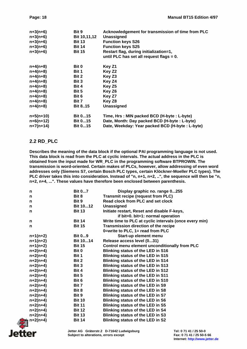
n+3(n+6) Bit 9 Acknowledgement for transmission of time from PLC n+3(n+6) Bit 10,11,12 Unassigned n+3(n+6) Bit 13 Function keys S26 n+3(n+6) Bit 14 Function keys S25 n+3(n+6) Bit 15 Restart flag, during initialization=1, until PLC has set all request flags = 0. n+4(n+8) Bit 0 Key Z1 n+4(n+8) Bit 1 Key Z2 n+4(n+8) Bit 2 Key Z3 n+4(n+8) Bit 3 Key Z4 n+4(n+8) Bit 4 Key Z5 n+4(n+8) Bit 5 Key Z6 n+4(n+8) Bit 6 Key Z7 n+4(n+8) Bit 7 Key Z8 n+4(n+8) Bit 8..15 Unassigned n+5(n+10) Bit 0...15 Time, Hrs : MIN packed BCD (H-byte : L-byte) n+6(n+12) Bit 0...15 Date, Month: Day packed BCD (H-byte : L-byte) n+7(n+14) Bit 0...15 Date, Weekday: Year packed BCD (H-byte : L-byte) 2.2 RD_PLC Describes the meaning of the data block if the optional PAI programming language is not used. This data block is read from the PLC at cyclic intervals. The actual address in the PLC is obtained from the input made for WR_PLC in the programming software BTPROWIN. The transmission is word-oriented. Certain makes of PLCs, however, allow addressing of even word addresses only (Siemens S7, certain Bosch PLC types, certain Klöckner-Moeller PLC types). The PLC driver takes this into consideration. Instead of "n, n+1, n+2, ..", the sequence will then be "n, n+2, n+4, ...". These values have therefore been enclosed between parenthesis. n Bit 0...7 Display graphic no. range 0...255 n Bit 8 Transmit recipe (request from PLC) n Bit 9 Read clock from PLC and set clock n Bit 10...12 Unassigned n Bit 13 Initiate restart, Reset and disable F-keys, if bit=0. bit=1: normal operation n Bit 14 Write time to PLC at cyclic intervals (once every min) n Bit 15 Transmission direction of the recipe
0=write to PLC, 1= read from PLC n+1(n+2) Bit 0...9 Start-up element menu n+1(n+2) Bit 10...14 Release access level (0...31) n+1(n+2) Bit 15 Control menu element unconditionally from PLC n+2(n+4) Bit 0 Blinking status of the LED in S16 n+2(n+4) Bit 1 Blinking status of the LED in S15 n+2(n+4) Bit 2 Blinking status of the LED in S14 n+2(n+4) Bit 3 Blinking status of the LED in S13 n+2(n+4) Bit 4 Blinking status of the LED in S12 n+2(n+4) Bit 5 Blinking status of the LED in S11 n+2(n+4) Bit 6 Blinking status of the LED in S10 n+2(n+4) Bit 7 Blinking status of the LED in S9 n+2(n+4) Bit 8 Blinking status of the LED in S8 n+2(n+4) Bit 9 Blinking status of the LED in S7 n+2(n+4) Bit 10 Blinking status of the LED in S6 n+2(n+4) Bit 11 Blinking status of the LED in S5 n+2(n+4) Bit 12 Blinking status of the LED in S4 n+2(n+4) Bit 13 Blinking status of the LED in S3 n+2(n+4) Bit 14 Blinking status of the LED in S2
Manual BT15 Edition 4/97 Page: 19
Tel: 0 71 41 / 25 50-0 Jetter AG Gräterstr.2 D-71642 Ludwigsburg Fax: 0 71 41 / 25 50-5 66 Subject to alterations, errors except Internet: http://www.jetter.de
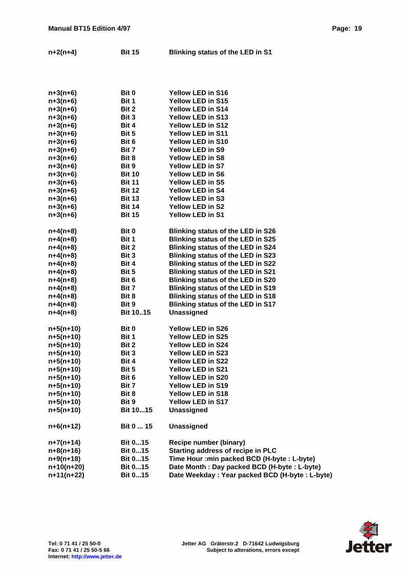
n+2(n+4) Bit 15 Blinking status of the LED in S1 n+3(n+6) Bit 0 Yellow LED in S16 n+3(n+6) Bit 1 Yellow LED in S15 n+3(n+6) Bit 2 Yellow LED in S14 n+3(n+6) Bit 3 Yellow LED in S13 n+3(n+6) Bit 4 Yellow LED in S12 n+3(n+6) Bit 5 Yellow LED in S11 n+3(n+6) Bit 6 Yellow LED in S10 n+3(n+6) Bit 7 Yellow LED in S9 n+3(n+6) Bit 8 Yellow LED in S8 n+3(n+6) Bit 9 Yellow LED in S7 n+3(n+6) Bit 10 Yellow LED in S6 n+3(n+6) Bit 11 Yellow LED in S5 n+3(n+6) Bit 12 Yellow LED in S4 n+3(n+6) Bit 13 Yellow LED in S3 n+3(n+6) Bit 14 Yellow LED in S2 n+3(n+6) Bit 15 Yellow LED in S1 n+4(n+8) Bit 0 Blinking status of the LED in S26 n+4(n+8) Bit 1 Blinking status of the LED in S25 n+4(n+8) Bit 2 Blinking status of the LED in S24 n+4(n+8) Bit 3 Blinking status of the LED in S23 n+4(n+8) Bit 4 Blinking status of the LED in S22 n+4(n+8) Bit 5 Blinking status of the LED in S21 n+4(n+8) Bit 6 Blinking status of the LED in S20 n+4(n+8) Bit 7 Blinking status of the LED in S19 n+4(n+8) Bit 8 Blinking status of the LED in S18 n+4(n+8) Bit 9 Blinking status of the LED in S17 n+4(n+8) Bit 10..15 Unassigned n+5(n+10) Bit 0 Yellow LED in S26 n+5(n+10) Bit 1 Yellow LED in S25 n+5(n+10) Bit 2 Yellow LED in S24 n+5(n+10) Bit 3 Yellow LED in S23 n+5(n+10) Bit 4 Yellow LED in S22 n+5(n+10) Bit 5 Yellow LED in S21 n+5(n+10) Bit 6 Yellow LED in S20 n+5(n+10) Bit 7 Yellow LED in S19 n+5(n+10) Bit 8 Yellow LED in S18 n+5(n+10) Bit 9 Yellow LED in S17 n+5(n+10) Bit 10...15 Unassigned n+6(n+12) Bit 0 ... 15 Unassigned n+7(n+14) Bit 0...15 Recipe number (binary) n+8(n+16) Bit 0...15 Starting address of recipe in PLC n+9(n+18) Bit 0...15 Time Hour :min packed BCD (H-byte : L-byte) n+10(n+20) Bit 0...15 Date Month : Day packed BCD (H-byte : L-byte) n+11(n+22) Bit 0...15 Date Weekday : Year packed BCD (H-byte : L-byte)

Page: 20 Manual BT15 Edition 4/97
Jetter AG Gräterstr.2 D-71642 Ludwigsburg Tel: 0 71 41 / 25 50-0 Subject to alterations, errors except Fax: 0 71 41 / 25 50-5 66 Internet: http://www.jetter.de
2.3 Handshake Procedure during Data Transfer A handshake procedure is required for all sequential functions to ensure a proper transmission from and to the PLC. The most efficient procedure compares 2 corresponding bits of the transmitter and receiver of a message and defines: Not identical = new message (request), Identical = message has been read or requested action accomplished (acknowledgement). This is the procedure that is used for the BT15. The procedure is as follows: 1. Request bit and acknowledgement bit do not match 2. Carry out requested action 3. Set acknowledgement bit to same state as request bit 2.4 Restart initiated by BT15 When restarting the PLC or BT15, the request bits must be synchronized with the acknowledgement bits. For this purpose, the restart flag (WR_PLC n+3.15) is set by the BT15 and is not reset until the PLC has set all request bits to zero and RD_PLC n.13 has been set to 1 by the PLC. After a restart, the BT15 sets all acknowledgement bits to zero. 2.5 Synchronization when a Restart is Initiated by the PLC The PLC sets bit 13 in RD_PLC. As long as this bit is reset, all F-keys are blocked and all latch-down keys are reset. The BT15 acknowledges with restart flag = 1. 2.6 Start-up Element Menu The PLC (or the PAI) can display a menu element in RD_PLC+1 (RD_PLC+2) bit 0...9 if no element is active or can call a menu element unconditionally by setting bit 15. If element 0 is called with the set bit 15, the menu bar display is suppressed. If a branch is made to the successive element "0" in the menu structure, the program jumps instead to the element preselected by the PLC. If the PLC specifies the element "0", the menu bar is deactivated if a branch is made to the element "0". The menu element that is currently active is indicated to the PLC in WR_PLC+1. 2.7 Variables / Variable Optimization For optimization of the transmission rate, up to 256 variables are combined to one block and are imaged to an internal memory area. The areas depend on the respective PLC and are described in the PLC-specific section of this manual.
Manual BT15 Edition 4/97 Page: 21
Tel: 0 71 41 / 25 50-0 Jetter AG Gräterstr.2 D-71642 Ludwigsburg Fax: 0 71 41 / 25 50-5 66 Subject to alterations, errors except Internet: http://www.jetter.de
2.8 Recipe Transfer The transmission of a recipe (= 1 line in a two-dimensional data array) requires programming of the following sequence in the PLC: 1. Entering of the recipe number in (RD_PLC+7) 2. Entering of the destination or source address in the PLC in (RD_PLC+8) 3. Setting of the transmission direction (RD_PLC.15) 4. Initiation of the transmission by inverting (RD_PLC.8) 5. Waiting for acknowledgement from BT15. Once the transmission is completed, the BT15 acknowledges the request by setting bit ( WR_PLC+3.8) to the same state as the request flag. The number of transmitted words is a result from the number of words per recipe (setting in the programming software). 2.9 Reading Clock from PLC and Setting Clock The sequence required to set the clock in the BT15 is analogous to the one required for recipe transmission. The valid time values must be available in RD_PLC+9 ... RD_PLC+11. 2.10 Transmitting Clock to PLC at Cyclic Intervals If bit (RD_PLC.14) corresponds to "1", the time will be transmitted to the PLC once every minute. For the duration of the transmission, the bit "variable transmission in progress" (WR_PLC.5) is set.
Page: 22 Manual BT15 Edition 4/97
Jetter AG Gräterstr.2 D-71642 Ludwigsburg Tel: 0 71 41 / 25 50-0 Subject to alterations, errors except Fax: 0 71 41 / 25 50-5 66 Internet: http://www.jetter.de
3. Programming Software Programming of the BT15 does not involve the exchange of memory modules but the transmission of data from the PC to the BT15 using the programming software "BTPROWIN" (under Windows ®, Windows 95® or Windows NT®) on the PC. The connection to the BT15 is established via the programming interface COM1: (of the BT15). On the PC-side, com1: to com4: can be selected. For ease of handling, the driver for the PLC being used is loaded to the BT15 together with the project data. To avoid this process from occurring every time, a corresponding switch is available in the programming software. Upon delivery, a simulation driver is loaded which simulates the connection to the PLC internally. System requirements: Hardware: Pointing device (mouse) 1 serial interface 386SX and higher minimum of 4 MB RAM minimum of 2 MB free memory on hard disk Software: Windows® 3.11 or higher, Windows95®, Windows NT® Drawing program for processing of bitmaps (.bmp). 3.1 Installation of the Programming Software The installation disk contains the programming software in a compressed format. To install BTPROWIN, the following steps must be carried out: Start Windows 3.xx from your hard disk Insert your BTPROWIN disk containing the installation program into drive A: or B: Activate the Program Manager Select:
File Execute Search a: (or b:) Install.exe
The installation is automatic. You will be prompted to specify the destination drive and the sub-directory to which the programming software is to be copied. The drivers for the PLC connection and the program "BTPROWIN" must be located in the same directory ("\BTPROWIN").
Manual BT15 Edition 4/97 Page: 23
Tel: 0 71 41 / 25 50-0 Jetter AG Gräterstr.2 D-71642 Ludwigsburg Fax: 0 71 41 / 25 50-5 66 Subject to alterations, errors except Internet: http://www.jetter.de
3.2 Starting the Programming Software Start BTPROWIN from within its program group (icon). Select "File" and choose: "New Project" "Open Project" "Exit”
If you select the item "New Project", a sample project "BT15.neu" (BT15.new) will be loaded. This is where you can store your own sample project by renaming the project data of your choice to "BT15.neu" (BT15.new). 3.2.1 Editing Project If you have opened an existing project or created a new project, select "Edit Project" at this point. Then begin defining the system set-up. 3.2.1.1 System Set-Up This is where your BT15 is configured. First of all, the driver to the PLC is selected. BTPROWIN requires information on the selected driver to represent the following windows accordingly. The PLC drivers are separate binary files which are not to be altered. 3.2.1.1.1 Device Set-Up This is where the RAM is divided into fault diagnosis, PAI-reservation and recipe memory. 3.2.1.1.1.2 Fault Diagnosis This is where the definition is made whether an automatic fault diagnosis through the evaluation of a bit field is to occur. The starting address and the size can be specified in word-mode. In addition, the definition is made here, whether a fault = bit set (working current principle) or a fault = bit reset (closed-circuit current principle). The setting New Value Message indicates that the most recent message of the highest priority is displayed. The setting First-up Message results in the fault message which was recognized first and which is of the highest priority to be displayed. The assignment of fault message texts is in bit-mode. Bit 0 of the first word = fault message 0. Fault message 0 has a special status: the bit field is reset and reread from the PLC. Bit 1 = first fault message, bit 15 = fault message 15. Bit 0 of the 2nd word = fault message 16, etc. The memory area for the diagnostic memory is reserved here in 1kByte steps. 3.2.1.1.1.3 Recipes The BT 15 is equipped with a recipe memory, provided the memory expansion board with real-time clock is installed. The memory is configured as a two-dimensional array. The parameter to be specified corresponds to the number of recipes and the number of entries per recipe. Each entry is a 16-bit word. The size of the memory required for the recipe memory is calculated on the basis of the defined "number of recipes" and "words/recipe". On account of the definition being made in word-mode (16 bits); it must be taken into account that 32-bit variables require 2 words. The length of ASCII variables depends on the respective definition (2 characters per word).
Page: 24 Manual BT15 Edition 4/97
Jetter AG Gräterstr.2 D-71642 Ludwigsburg Tel: 0 71 41 / 25 50-0 Subject to alterations, errors except Fax: 0 71 41 / 25 50-5 66 Internet: http://www.jetter.de
3.2.1.1.1.4 Blinking Intervals Text items as well as LEDs in the function keys are capable of blinking independently. This is where the "ON" and "OFF" intervals can be defined. The value settings apply to blinking texts, blinking variables and blinking LEDs in the function keys. 3.2.1.1.2 Keyboard Set-Up Each of the 26 function keys (S1 .. S26) can be programmed as a push-button key or as a latch-down key. Each LED in the function keys is either capable of indicating the state of the (latch-down) key (=internal) or the state of an assigned bit in the PLC (=external). The assignment LED - PLC is defined in RD_PLC. The assignment key - PLC is contained in WR_PLC. The 26 function keys can be combined to radio groups. Radio keys are keys that mutually activate. A radio group is identified by being assigned the same group number in the programming software BTPROWIN. 3.2.1.1.3 Driver Set-Up 3.2.1.1.3.1 Network Address: This value is applicable if the PLC driver allows several stations. This value must be specified even if the physical design of the interface (RS232, TTY) permits only a point-to-point connection. 3.2.1.1.3.2 RD_PLC: This is where the starting address is specified from which onwards the "RD_PLC" block is read from the PLC. This does not affect the reading and writing of variables. 3.2.1.1.3.3 WR_PLC: This is where the starting address is specified from which onwards the "WR_PLC" block is written to the PLC. This does not affect the reading and writing of variables. 3.2.1.1.3.4 Variable Address Min, Max.: This is where the maximum read and write range for variables is defined. This monitoring process is particularly important if indexed variables are used since, in the case of programming errors, write operations outside of the permitted range might occur. The index is read at the operating time of the PLC, which means that such a programming error can not be prevented by the programming software BTPROWIN. 3.2.1.2 Variable Definition Variables are globally defined in the programming software BTPROWIN and may then be used in messages and menus. Each variable has a name, a format, a parameter and an address. BTPROWIN is capable of sorting the variables in accordance with their name, address or format.
Manual BT15 Edition 4/97 Page: 25
Tel: 0 71 41 / 25 50-0 Jetter AG Gräterstr.2 D-71642 Ludwigsburg Fax: 0 71 41 / 25 50-5 66 Subject to alterations, errors except Internet: http://www.jetter.de
3.2.1.2.1 Editing Variables A variable is selected from a list and its properties can be modified in a window which appears after the selection of the function "Edit". Modification of the variable format at a later date is not possible. The parameters of a variable depend on the variable format. The "TEXT" is composed of filler characters (_) and fixed texts. The filler characters are replaced at operating time with variables from the PLC. In the case of symbol variables, the number of the object variable list is specified as parameter. For level indicator variables, the name of the graphics file containing the filling area is specified. 3.2.1.3 Editing Background Graphics Up to 256 background graphics can be created. Background graphics consist of bitmaps, up to 30 message definitions and level indicator variables. Up to 250 variables can simultaneously be displayed on the screen. This number is made up of the variables in the message definitions in the background graphic, the level indicator variables in the background graphic, the symbol variables as well as the variables in the currently active menu element. The following functions are available: "Insert Bitmap", "Insert Message Window", "Insert Variable", "Delete Element", "Object to Foreground" and "Object to Background". 3.2.1.4 Message Editor The message editor for the process, system and fault messages differentiates between the text mode (Ctrl+T) and graphics mode (Ctrl+G). In graphics mode, graphic and text elements are placed. In the text mode, texts are written, variables are inserted and font attributes are set. 3.2.1.5 Editing Process Messages Process messages are capable of containing texts, variables and bitmaps. If the editor is activated from within the message definition, the size of the labeling fields is the same as the size of the message definition. If the editor is activated directly, the labeling fields are displayed in accordance with a default size. 3.2.1.6 Editing System Messages The editor for system messages is similar to the editor for process messages. The meaning of the individual messages is predefined (see 1.1.0). In this context, it must be taken into account that filler characters are inserted for variables in some of the messages without a variable being defined. The order and meaning of filler characters is fixed. 3.2.1.7 Editing Fault Messages The message window of fault messages has a fixed size. Fault messages are capable of containing text items, but not variables. Software tools which allow direct importing of fault messages from text files are in preparation.
Page: 26 Manual BT15 Edition 4/97
Jetter AG Gräterstr.2 D-71642 Ludwigsburg Tel: 0 71 41 / 25 50-0 Subject to alterations, errors except Fax: 0 71 41 / 25 50-5 66 Internet: http://www.jetter.de
3.2.1.8 Editing the Menu Structure A description of the menu logic and the function of the menu elements has already been given in paragraph 1.5. The programming software "BTPROWIN" displays each of the 5 menu function keys with one labeling field for "OFF" and one for "ON". The element no., access level and word address are displayed in the upper menu button. The PLC word address and the access level must have been specified before programming of the keys in a new menu element is possible. The button "GO" can be used to jump to a specific menu element or to create a new element. Each of the 5 menu function keys is defined as a menu switching key (see 1.5.2), as "direct input" (see 1.5.3) or successive menu key (see 1.5.4). Selecting the button next to the labeling fields causes the associated input window to be displayed. The function of the menu structure can be simulated using the programming software BTPROWIN. By simply pressing the mouse button, it is possible to switch to a successive element with the programming software. 3.2.1.9 Editing Object Variables Object variables are required for symbol variables. Object variables are edited the same way as messages. They are also capable of containing texts and bitmaps. It is, however, not possible to insert variables (nesting depth too large). The size of the window can be modified by adjusting the separation line at the top of the first window (top left).

Manual BT15 Edition 4/97 Page: 27
Tel: 0 71 41 / 25 50-0 Jetter AG Gräterstr.2 D-71642 Ludwigsburg Fax: 0 71 41 / 25 50-5 66 Subject to alterations, errors except Internet: http://www.jetter.de
4. Connecting to the PLC This section deals with the part of the BT 15 that is specific to the PLC. Here, you will find an explanation of what interface hardware is needed, what the assignments of the connecting cable to the PLC should look like and how the data is stored in the PLC. Special PLC software (data handling blocks) are needed for some makes of PLCs. Wherever necessary, the programs are mentioned in this description. An integrated PG-MUX is available for a number of PLC makes. Their availability and limits are described here. Wiring layout, shielding and measures to prevent interference voltage. When using 24V power supplies, attention must be paid to reliable electrical isolation of the extra-low voltage. The safety and accident prevention regulations applicable to the application must be observed and obeyed. Machines and systems that feature operator panels are subject to the relevant EN, IEC and VDE regulations. The layout of components in the control cabinet has an essential influence on undisturbed functioning of a system or machine. During the course of planning and realization, attention must be paid to ensuring that the power and control sections are arranged separately. Ebelt GmbH operator panels are connected to your machines by two kinds of lines: 1. Power supply lines 2. Data lines Power supply lines are generally laid as unshielded lines. Only in the event of extreme electromagnetic influences may shielding be necessary. In such cases, however, it is better to shield the interference source. The data lines are laid as shielded lines. In order to avoid equalizing currents in the shield, the shield is grounded directly with low impedance on the one side and is isolated on the other end via a capacitor. Always use metallic or metallized connector housings. The braided shield should be connected over as large a surface of the connector housing as possible and with good electrical conduction. Selection of the data line depends on its length and on expected interference sources. Do not route data and power supply lines within the same shield. The lengths of lines between the operator panel and the PLC must not exceed the values that have been approved by the PLC manufacturer. Do not choose a line length that is longer than necessary. Always observe the PLC manufacturer's installation commands because, in many cases, the specifications applicable to the PLC interface are much stricter than would be necessary for reliable operation of the panel. If the line to the operator panel should be longer than is permitted by the PLC manufacturer's specifications, we offer corresponding interface converters featuring electrical isolation. For spur lines on a bus line, we recommend the use of our SKV485 interface distributor. Programming Cable Cable for BT 15 programming. The interface COM1: (RS232) is used to load the project data, the PAI program and the PLC driver from the PC to the BT15.
Page: 28 Manual BT15 Edition 4/97
Jetter AG Gräterstr.2 D-71642 Ludwigsburg Tel: 0 71 41 / 25 50-0 Subject to alterations, errors except Fax: 0 71 41 / 25 50-5 66 Internet: http://www.jetter.de
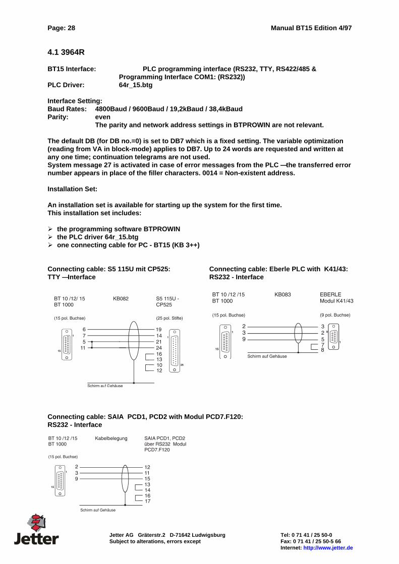
4.1 3964R BT15 Interface: PLC programming interface (RS232, TTY, RS422/485 &
Programming Interface COM1: (RS232)) PLC Driver: 64r_15.btg Interface Setting: Baud Rates: 4800Baud / 9600Baud / 19,2kBaud / 38,4kBaud Parity: even
The parity and network address settings in BTPROWIN are not relevant. The default DB (for DB no.=0) is set to DB7 which is a fixed setting. The variable optimization (reading from VA in block-mode) applies to DB7. Up to 24 words are requested and written at any one time; continuation telegrams are not used. System message 27 is activated in case of error messages from the PLC — the transferred error number appears in place of the filler characters. 0014 = Non-existent address. Installation Set: An installation set is available for starting up the system for the first time. This installation set includes: the programming software BTPROWIN the PLC driver 64r_15.btg one connecting cable for PC - BT15 (KB 3++)
Connecting cable: S5 115U mit CP525: Connecting cable: Eberle PLC with K41/43: TTY — Interface RS232 - Interface
Connecting cable: SAIA PCD1, PCD2 with Modul PCD7.F120: RS232 - Interface
Manual BT15 Edition 4/97 Page: 29
Tel: 0 71 41 / 25 50-0 Jetter AG Gräterstr.2 D-71642 Ludwigsburg Fax: 0 71 41 / 25 50-5 66 Subject to alterations, errors except Internet: http://www.jetter.de
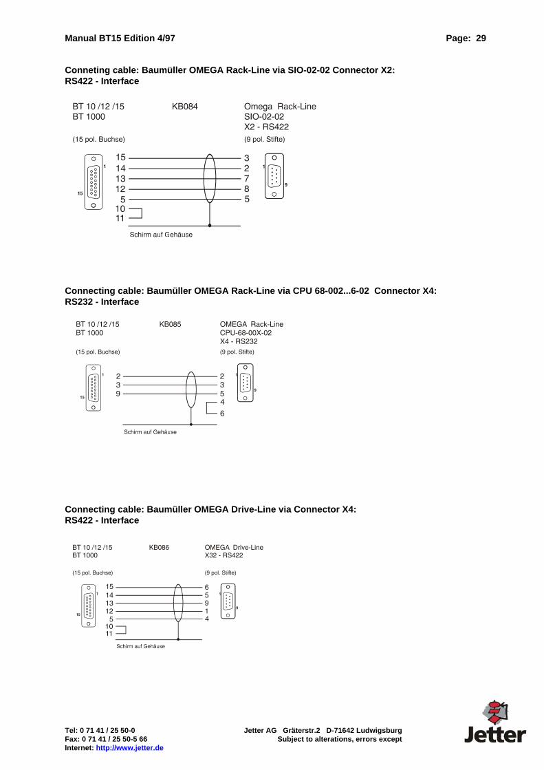
Conneting cable: Baumüller OMEGA Rack-Line via SIO-02-02 Connector X2: RS422 - Interface Connecting cable: Baumüller OMEGA Rack-Line via CPU 68-002...6-02 Connector X4: RS232 - Interface Connecting cable: Baumüller OMEGA Drive-Line via Connector X4: RS422 - Interface

Page: 30 Manual BT15 Edition 4/97
Jetter AG Gräterstr.2 D-71642 Ludwigsburg Tel: 0 71 41 / 25 50-0 Subject to alterations, errors except Fax: 0 71 41 / 25 50-5 66 Internet: http://www.jetter.de
4.2 AEG - Modicon A120 / A250 (KS-Functions) Order Designations BT15 Interface: PLC programming interface (RS232, TTY, RS422/485 &
Programming interface COM1: (RS232)) PLC Driver: AEG12xxx.btg Interface Setting: KS-Functions/ 9600 Baud / 8 Bits / Odd Parity / 1 Stop Bit The RS232 interface (electrically isolated) is used. Installation Set: An installation set is available for starting up the system for the first time. This installation set includes: the programming software BTPROWIN the PLC driver AEG12xxx.btg one connecting cable for PC - BT15 (KB 3++) one connecting cable for A120/A250 - BT15 (KB047)
Connecting cable:
Data Transfer BT15 <-> PLC The data transfer is accomplished in flag words. When parameterizing RD_PLC and WR_PLC as well as the variables, it must be ensured that the flag words that are used have been programmed in the PLC. Address range for variables: MW 1 ... MW 9999 Address range for RD_PLC/WR_PLC: MW 1 ... MW 9980 System message 27 is activated if error messages from the PLC occur. The error number transmitted by the PLC is entered in the filler characters. Error 06 : Out-of-Range (the requested data can not be accessed in the PLC.)

Manual BT15 Edition 4/97 Page: 31
Tel: 0 71 41 / 25 50-0 Jetter AG Gräterstr.2 D-71642 Ludwigsburg Fax: 0 71 41 / 25 50-5 66 Subject to alterations, errors except Internet: http://www.jetter.de
4.3 Allen-Bradley DF1 Order Designations BT15 Interface: PLC programming interface (RS232, TTY, RS422/485 &
Programming Interface COM1: (RS232)) PLC Driver: AB_12xxx.btg The RS232 interface (electrically isolated) is used. Settings for Channel 0 (SLC-5/xx, PLC-5/xx): PLC Address: 31 decimal or 77 octal Baud Rate: 19,2kBaud Stop Bits: 2 Control Line: NO Handshake Duplicate detect: On ACK Timeout: 10 MSG appl timeout: 1 Parity: Even Error Detect: CRC Nak Receive: 5 DF1 ENQ: 5 Installation Set: An installation set is available for starting up the system for the first time. This installation set includes: the programming software BTPROWIN the PLC driver AB_12xxx.btg one connecting cable for PC - BT15 (KB 3++) one connecting cable for SLC 5/03 - BT15 (KBxxx) one connecting cable for PLC 5/30 - BT15 (KBxxx)
Connecting cable:
Page: 32 Manual BT15 Edition 4/97
Jetter AG Gräterstr.2 D-71642 Ludwigsburg Tel: 0 71 41 / 25 50-0 Subject to alterations, errors except Fax: 0 71 41 / 25 50-5 66 Internet: http://www.jetter.de
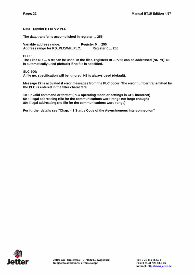
Data Transfer BT15 <-> PLC The data transfer is accomplished in register ... 255 Variable address range: Register 0 ... 255 Address range for RD_PLC/WR_PLC: Register 0 ... 255 PLC 5: The Files N 7 ... N 99 can be used. In the files, registers r0 ... r255 can be addressed (NN:rrr). N9 is automatically used (default) if no file is specified. SLC 500: A file no. specification will be ignored. N9 is always used (default). Message 27 is activated if error messages from the PLC occur. The error number transmitted by the PLC is entered in the filler characters. 10 : Invalid command or format (PLC operating mode or settings in CH0 incorrect) 50 : Illegal addressing (file for the communications word range not large enough) 80: Illegal addressing (no file for the communications word range) For further details see "Chap. 4.1 Status Code of the Asynchronous Interconnection"

Manual BT15 Edition 4/97 Page: 33
Tel: 0 71 41 / 25 50-0 Jetter AG Gräterstr.2 D-71642 Ludwigsburg Fax: 0 71 41 / 25 50-5 66 Subject to alterations, errors except Internet: http://www.jetter.de
4.4 MODBUS RTU Order Designations BT15 Interface: PLC programming interface (RS232, TTY, RS422/485 &
Programming Interface COM1: (RS232)) PLC Driver: MB_12xxx.btg The RS232 interface (electrically isolated) is used. Interface Setting: Baud Rates: 4800Baud / 9600Baud / 19,2kBaud / 38,4kBaud Parity: even / odd / none Installation Set: An installation set is available for starting up the system for the first time. This installation set includes: the programming software BTPROWIN the PLC driver MB_12xxx.btg one connecting cable for PC - BT15 (KB 3++) one connecting cable for Modicon 984 - BT15 (KB054)
Connecting cable:
BT 15 is Modbus master. The operating system is designed for communication with precisely one slave. The network address is programmed in the system set-up function of BTPROWIN.
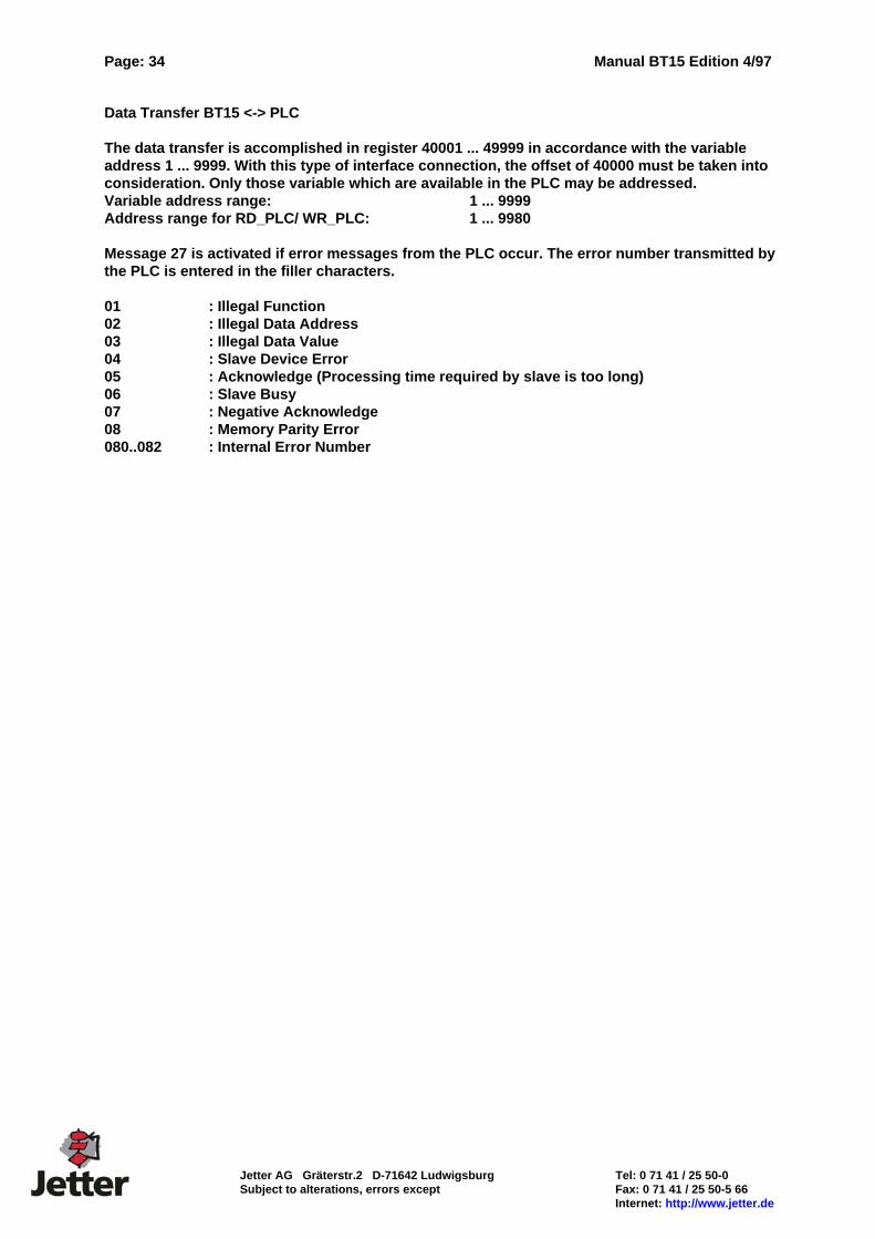
Page: 34 Manual BT15 Edition 4/97
Jetter AG Gräterstr.2 D-71642 Ludwigsburg Tel: 0 71 41 / 25 50-0 Subject to alterations, errors except Fax: 0 71 41 / 25 50-5 66 Internet: http://www.jetter.de
Data Transfer BT15 <-> PLC The data transfer is accomplished in register 40001 ... 49999 in accordance with the variable address 1 ... 9999. With this type of interface connection, the offset of 40000 must be taken into consideration. Only those variable which are available in the PLC may be addressed. Variable address range: 1 ... 9999 Address range for RD_PLC/ WR_PLC: 1 ... 9980 Message 27 is activated if error messages from the PLC occur. The error number transmitted by the PLC is entered in the filler characters. 01 : Illegal Function 02 : Illegal Data Address 03 : Illegal Data Value 04 : Slave Device Error 05 : Acknowledge (Processing time required by slave is too long) 06 : Slave Busy 07 : Negative Acknowledge 08 : Memory Parity Error 080..082 : Internal Error Number
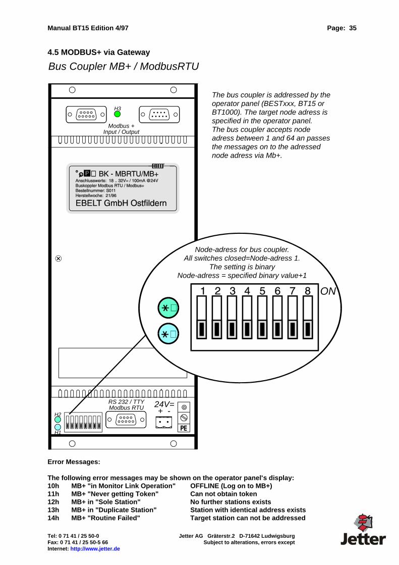
Manual BT15 Edition 4/97 Page: 35
Tel: 0 71 41 / 25 50-0 Jetter AG Gräterstr.2 D-71642 Ludwigsburg Fax: 0 71 41 / 25 50-5 66 Subject to alterations, errors except Internet: http://www.jetter.de
4.5 MODBUS+ via Gateway
Error Messages: The following error messages may be shown on the operator panel's display: 10h MB+ "in Monitor Link Operation" OFFLINE (Log on to MB+) 11h MB+ "Never getting Token" Can not obtain token 12h MB+ in "Sole Station" No further stations exists 13h MB+ in "Duplicate Station" Station with identical address exists 14h MB+ "Routine Failed" Target station can not be addressed
Bus Coupler MB+ / ModbusRTU
RS 232 / TTYModbus RTU
Modbus +Input / Output
24V=+ -
Node-adress for bus coupler.All switches closed=Node-adress 1.
The setting is binaryNode-adress = specified binary value+1
ON
H1
H2
H3
The bus coupler is addressed by theoperator panel (BESTxxx, BT15 orBT1000). The target node adress isspecified in the operator panel.The bus coupler accepts nodeadress between 1 and 64 an passesthe messages on to the adressednode adress via Mb+.
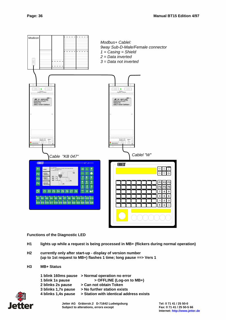
Page: 36 Manual BT15 Edition 4/97
Jetter AG Gräterstr.2 D-71642 Ludwigsburg Tel: 0 71 41 / 25 50-0 Subject to alterations, errors except Fax: 0 71 41 / 25 50-5 66 Internet: http://www.jetter.de
Functions of the Diagnostic LED H1 lights up while a request is being processed in MB+ (flickers during normal operation) H2 currently only after start-up - display of version number
(up to 1st request to MB+) flashes 1 time; long pause ==> Vers 1 H3 MB+ Status 1 blink 160ms pause > Normal operation no error 1 blink 1s pause > OFFLINE (Log-on to MB+) 2 blinks 2s pause > Can not obtain Token 3 blinks 1,7s pause > No further station exists 4 blinks 1,4s pause > Station with identical address exists
Modicon
RS 232 / TTYModbus RTU
Modbus +Eingang / Ausgang
24V=+ -
RS 232 / TTYModbus RTU
Modbus +Eingang / Ausgang
24V=+ -
i
Cable "KB 047" Cablel "W"
Modbus+ Cablel:9way Sub-D-Male/Female connector1 = Casing = Shield2 = Data inverted3 = Data not inverted
0
9GHI
4JKL
5MNO
7ABC
8DEF
.+/-
6PQR
1STU
2VWX
3YZ-
ESC
BT 15
St rmeldungen:M: 0007 S: 24.2.95 15.12 R: 24.95 15.20 Dauer 00h 8min
NOT-AUS bet tigt**** Ende der LISTE
Temperatur:84,3 Grad
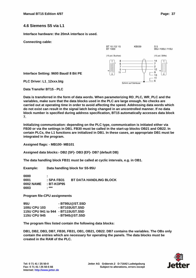
Manual BT15 Edition 4/97 Page: 37
Tel: 0 71 41 / 25 50-0 Jetter AG Gräterstr.2 D-71642 Ludwigsburg Fax: 0 71 41 / 25 50-5 66 Subject to alterations, errors except Internet: http://www.jetter.de
4.6 Siemens S5 via L1 Interface hardware: the 20mA interface is used. Connecting cable: Interface Setting: 9600 Baud/ 8 Bit PE PLC Driver: L1_12xxx.btg Data Transfer BT15 - PLC Data is transferred in the form of data words. When parameterizing RD_PLC, WR_PLC and the variables, make sure that the data blocks used in the PLC are large enough. No checks are carried out at operating time in order to avoid affecting the speed. Addressing data words which do not exist can result in the signal latch being changed in an uncontrolled manner. If no data block number is specified during address specification, BT15 automatically accesses data block 7. Initializing communication: depending on the PLC type, communication is initiated either via FB30 or via the settings in DB1. FB30 must be called in the start-up blocks OB21 and OB22. In certain PLCs, the L1 functions are initialized in DB1. In these cases, an appropriate DB1 must be integrated in the program. Assigned flags: - MB100- MB101 Assigned data blocks:- DB2 (SF)- DB3 (EF)- DB7 (default DB) The data handling block FB31 must be called at cyclic intervals, e.g. in OB1. Example: Data handling block for S5-95U 0000 : 0001 : SPA FB31 BT DATA HANDLING BLOCK 0002 NAME : BT-KOP95 0003 : *** Program file-CPU assignments 95U - [email protected] 100U CPU 103 - BT103UST.S5D 115U CPU 941 to 944 - BT115UST.S5D 115U CPU 945 - [email protected] The program files listed contain the following data blocks: DB1, DB2, DB3, DB7, FB30, FB31, OB1, OB21, OB22. DB7 contains the variables. The OBs only contain the entries which are necessary for operating the panels. The data blocks must be created in the RAM of the PLC.
Page: 38 Manual BT15 Edition 4/97
Jetter AG Gräterstr.2 D-71642 Ludwigsburg Tel: 0 71 41 / 25 50-0 Subject to alterations, errors except Fax: 0 71 41 / 25 50-5 66 Internet: http://www.jetter.de
4.7 Siemens S5 115U .. 155U via SAS525 We offer the interface cards SAS525 -16 and SAS525 -CL for series S5 115U .. S5 155U controllers. Depending on the volume of data to be transferred between the PLC and operator panel, up to 16 devices can be connected to one interface card. Mixed operation with BT15 and other operator panels manufactured by EBELT are possible. Data transfer principle All data between the interface card SAS525-16 and the operator panels is transferred serially via a two-wire cable (RS485). Transmission securing is byte by byte by means of a parity check and block by block via a BCC. Any transmission errors are acknowledged automatically, i.e. a fault is suppressed by the telegram being repeated and is not noticed by the user unless it occurs continuously. Order designations Interface card: SAS525-16 (with RS485 module) SAS525-CL (with 20mA module) BT 15: with standard interface module PLC driver: SAS12xxx.btg Installation set SAS525-16 An installation set is available for starting up the system for the first time. The installation set includes: the necessary data handling blocks for the PLC the programming software BTPROWIN the PLC driver SAS12xxx.btg one connecting cable for PC - BT 15 one connecting cable for SAS525 - BT 15
The installation set is only required once when the system is started up for the first time. Connecting cables can be cut to length and terminated in accordance with your requirements. Structure of the interface card The interface card SAS525-16 is a double-eurocard-size printed-circuit board with two 48-way base connectors in the ES902 rack system. The mounting depth is 1 1/3 standard slots. A 25-way min. D female connector for the RS485 interface is located at the front. The interface card is powered via the PLC power supply unit (+5V). The current consumption is approx. 500mA.
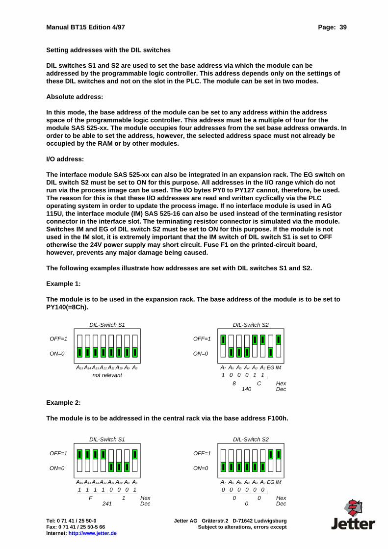
Manual BT15 Edition 4/97 Page: 39
Tel: 0 71 41 / 25 50-0 Jetter AG Gräterstr.2 D-71642 Ludwigsburg Fax: 0 71 41 / 25 50-5 66 Subject to alterations, errors except Internet: http://www.jetter.de
Setting addresses with the DIL switches DIL switches S1 and S2 are used to set the base address via which the module can be addressed by the programmable logic controller. This address depends only on the settings of these DIL switches and not on the slot in the PLC. The module can be set in two modes. Absolute address: In this mode, the base address of the module can be set to any address within the address space of the programmable logic controller. This address must be a multiple of four for the module SAS 525-xx. The module occupies four addresses from the set base address onwards. In order to be able to set the address, however, the selected address space must not already be occupied by the RAM or by other modules. I/O address: The interface module SAS 525-xx can also be integrated in an expansion rack. The EG switch on DIL switch S2 must be set to ON for this purpose. All addresses in the I/O range which do not run via the process image can be used. The I/O bytes PY0 to PY127 cannot, therefore, be used. The reason for this is that these I/O addresses are read and written cyclically via the PLC operating system in order to update the process image. If no interface module is used in AG 115U, the interface module (IM) SAS 525-16 can also be used instead of the terminating resistor connector in the interface slot. The terminating resistor connector is simulated via the module. Switches IM and EG of DIL switch S2 must be set to ON for this purpose. If the module is not used in the IM slot, it is extremely important that the IM switch of DIL switch S1 is set to OFF otherwise the 24V power supply may short circuit. Fuse F1 on the printed-circuit board, however, prevents any major damage being caused. The following examples illustrate how addresses are set with DIL switches S1 and S2. Example 1: The module is to be used in the expansion rack. The base address of the module is to be set to PY140(=8Ch).
Example 2: The module is to be addressed in the central rack via the base address F100h.
A15 A14 A13 A12 A11 A10 A9 A8
ON=0
OFF=1
DIL-Switch S1
not relevant
A7 A6 A5 A4 A3 A2 EG IM
1 0 0 0 1 1
8 C140
HexDec
ON=0
OFF=1
DIL-Switch S2
A7 A6 A5 A4 A3 A2 EG IM
0 0 0 0 0 0
0 00
HexDec
ON=0
OFF=1
DIL-Switch S2
A15 A14 A13 A12 A11 A10 A9 A8
1 1 1 1 0 0 0 1
F 1241
HexDec
ON=0
OFF=1
DIL-Switch S1
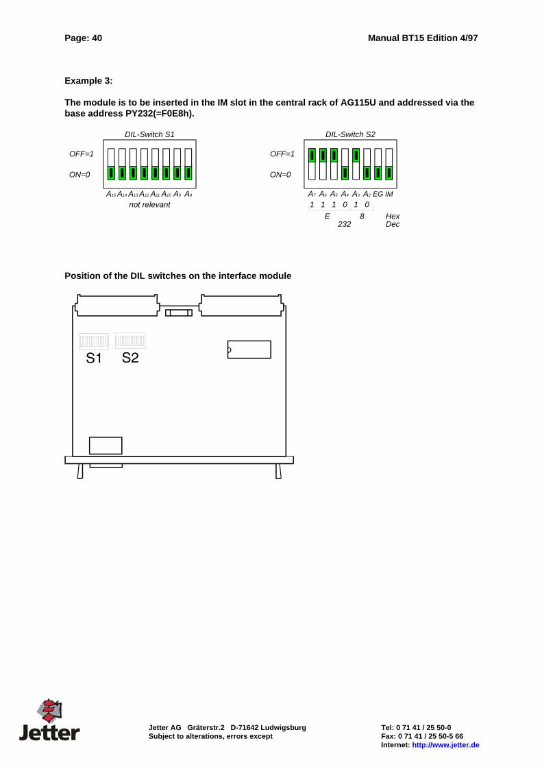
Page: 40 Manual BT15 Edition 4/97
Jetter AG Gräterstr.2 D-71642 Ludwigsburg Tel: 0 71 41 / 25 50-0 Subject to alterations, errors except Fax: 0 71 41 / 25 50-5 66 Internet: http://www.jetter.de
Example 3: The module is to be inserted in the IM slot in the central rack of AG115U and addressed via the base address PY232(=F0E8h).
Position of the DIL switches on the interface module
A7 A6 A5 A4 A3 A2 EG IM
1 1 1 0 1 0
E 8232
HexDec
ON=0
OFF=1
DIL-Switch S2
A15 A14 A13 A12 A11 A10 A9 A8
ON=0
OFF=1
DIL-Switch S1
not relevant
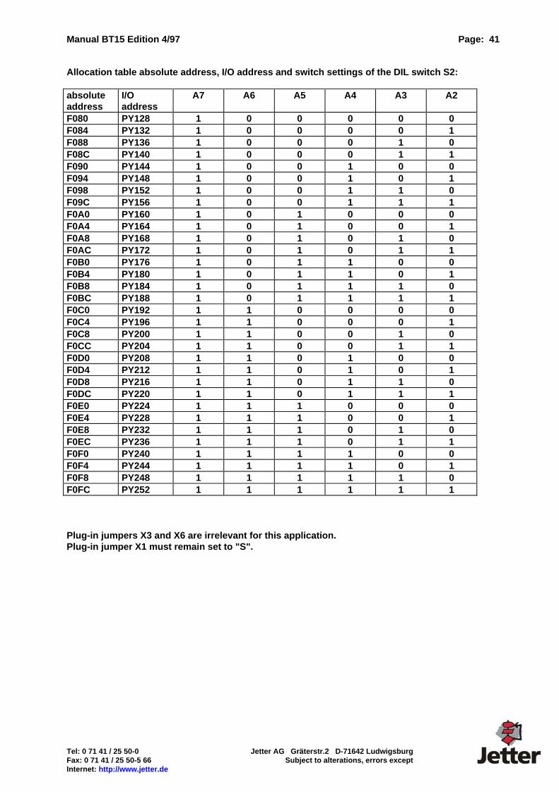
Manual BT15 Edition 4/97 Page: 41
Tel: 0 71 41 / 25 50-0 Jetter AG Gräterstr.2 D-71642 Ludwigsburg Fax: 0 71 41 / 25 50-5 66 Subject to alterations, errors except Internet: http://www.jetter.de
Allocation table absolute address, I/O address and switch settings of the DIL switch S2: absolute address
I/O address
A7 A6 A5 A4 A3 A2
F080 PY128 1 0 0 0 0 0 F084 PY132 1 0 0 0 0 1 F088 PY136 1 0 0 0 1 0 F08C PY140 1 0 0 0 1 1 F090 PY144 1 0 0 1 0 0 F094 PY148 1 0 0 1 0 1 F098 PY152 1 0 0 1 1 0 F09C PY156 1 0 0 1 1 1 F0A0 PY160 1 0 1 0 0 0 F0A4 PY164 1 0 1 0 0 1 F0A8 PY168 1 0 1 0 1 0 F0AC PY172 1 0 1 0 1 1 F0B0 PY176 1 0 1 1 0 0 F0B4 PY180 1 0 1 1 0 1 F0B8 PY184 1 0 1 1 1 0 F0BC PY188 1 0 1 1 1 1 F0C0 PY192 1 1 0 0 0 0 F0C4 PY196 1 1 0 0 0 1 F0C8 PY200 1 1 0 0 1 0 F0CC PY204 1 1 0 0 1 1 F0D0 PY208 1 1 0 1 0 0 F0D4 PY212 1 1 0 1 0 1 F0D8 PY216 1 1 0 1 1 0 F0DC PY220 1 1 0 1 1 1 F0E0 PY224 1 1 1 0 0 0 F0E4 PY228 1 1 1 0 0 1 F0E8 PY232 1 1 1 0 1 0 F0EC PY236 1 1 1 0 1 1 F0F0 PY240 1 1 1 1 0 0 F0F4 PY244 1 1 1 1 0 1 F0F8 PY248 1 1 1 1 1 0 F0FC PY252 1 1 1 1 1 1 Plug-in jumpers X3 and X6 are irrelevant for this application. Plug-in jumper X1 must remain set to "S".
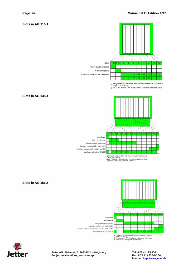
Page: 42 Manual BT15 Edition 4/97
Jetter AG Gräterstr.2 D-71642 Ludwigsburg Tel: 0 71 41 / 25 50-0 Subject to alterations, errors except Fax: 0 71 41 / 25 50-5 66 Internet: http://www.jetter.de
Slots in AG 115U Slots in AG 135U Slots in AG 155U
321
1) 1) 1) 1) 1) 1) 3)
2) 2) 2) 2) 2) 2) 3)
0CPUPS 4 5 6 IMSlots
Power supply module
Central module
Interface module SAS523/525
1) Plugable with modules with three-row socket connectorstrip (CR 700-2).
2) 24 V for active TTY interface is available at these slots.
Coordinator
R-, S-, M-processor
Communications processors
Interface modules 300-5 oder 301-5
Interface modules 300-3, 301-3 und 302
Interface module SAS 523/525
837567595143352719113
2) 2) 2) 2) 2) 2) 2)
91 99 107 115 123 131 139 147 155 183
1) Plugable with modules with three-row socket connectorstrip (CR 700-2).
2) 24 V for active TTY interface is available at these slots.3) Note custom setting with DIL switches.
Coordinator
Central module
Communication processors
Interface modules 300-5 oder 301-5
Interface modules 300-3, 301-3 und 308-3 oder 301-5
Interface module SAS 523/525
837567595143352719113
2) 2) 2) 2) 2) 2) 2) 2) 2) 2) 2) 2) 2)
91 99 107 115 123 131 139 147 155 183
1) Plugable with modules with three-row socket connectorstrip (CR 700-2).
2) 24 V for active TTY interface is available at these slots.3) Note custom setting with DIL switches.
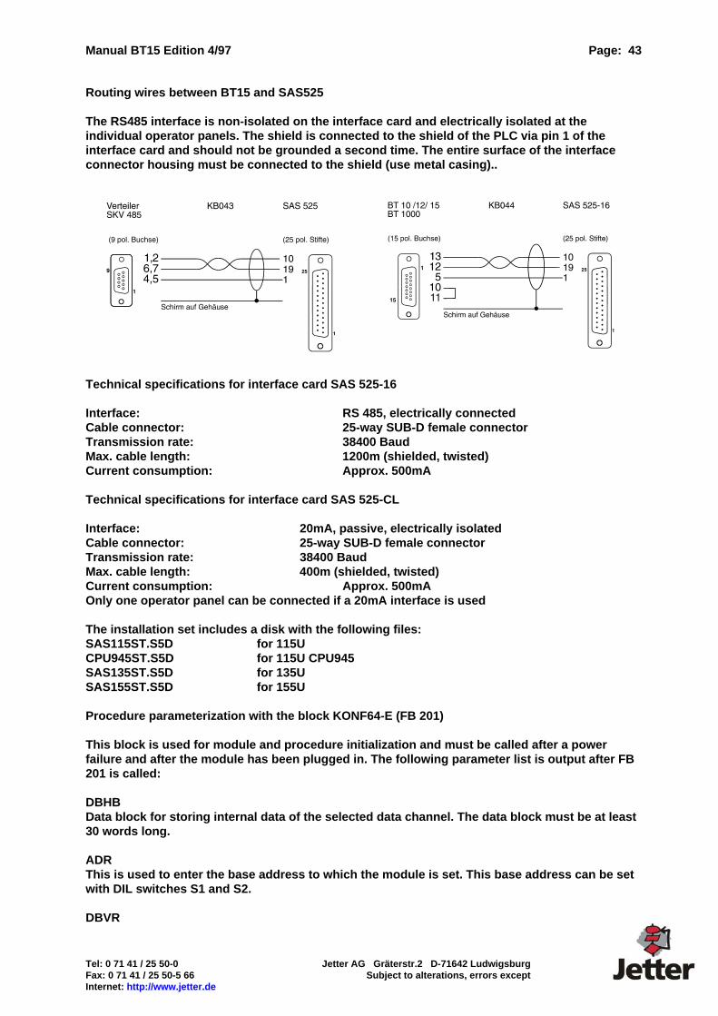
Manual BT15 Edition 4/97 Page: 43
Tel: 0 71 41 / 25 50-0 Jetter AG Gräterstr.2 D-71642 Ludwigsburg Fax: 0 71 41 / 25 50-5 66 Subject to alterations, errors except Internet: http://www.jetter.de
Routing wires between BT15 and SAS525 The RS485 interface is non-isolated on the interface card and electrically isolated at the individual operator panels. The shield is connected to the shield of the PLC via pin 1 of the interface card and should not be grounded a second time. The entire surface of the interface connector housing must be connected to the shield (use metal casing)..
Technical specifications for interface card SAS 525-16 Interface: RS 485, electrically connected Cable connector: 25-way SUB-D female connector Transmission rate: 38400 Baud Max. cable length: 1200m (shielded, twisted) Current consumption: Approx. 500mA Technical specifications for interface card SAS 525-CL Interface: 20mA, passive, electrically isolated Cable connector: 25-way SUB-D female connector Transmission rate: 38400 Baud Max. cable length: 400m (shielded, twisted) Current consumption: Approx. 500mA Only one operator panel can be connected if a 20mA interface is used The installation set includes a disk with the following files: SAS115ST.S5D for 115U CPU945ST.S5D for 115U CPU945 SAS135ST.S5D for 135U SAS155ST.S5D for 155U Procedure parameterization with the block KONF64-E (FB 201) This block is used for module and procedure initialization and must be called after a power failure and after the module has been plugged in. The following parameter list is output after FB 201 is called: DBHB Data block for storing internal data of the selected data channel. The data block must be at least 30 words long. ADR This is used to enter the base address to which the module is set. This base address can be set with DIL switches S1 and S2. DBVR
Page: 44 Manual BT15 Edition 4/97
Jetter AG Gräterstr.2 D-71642 Ludwigsburg Tel: 0 71 41 / 25 50-0 Subject to alterations, errors except Fax: 0 71 41 / 25 50-5 66 Internet: http://www.jetter.de
This is used to enter the data block which is to be valid for handling variables if the variable address is specified without a DB number when text is generated on the operator panel. Passive data handling block (FB195) Block FB195 establishes the connection between SAS 525-xx and the S5 program. The block must be called at least once in a cycle. In the case of longer PLC cycle times, FB195 can be called several times (every 30ms). The response time is thus shortened. The block requires a data block with a minimum length of 30 words for managing the internal data. The data block specified here must be the same as that for FB 201 (KONF64-E). Auxiliary blocks FB198/199 These blocks must be loaded in the PLC. They contain internal auxiliary routines and are called by the data handling block (FB195). The auxiliary blocks cannot be listed. Error messages If an error occurs, the interface card SAS 525-xx should be started up in precisely the specified sequence. The following errors can occur: Incorrect channel number Data block (HTDB) for internal data does not exist or is too short. Interface card hardware error Incorrect wiring Operator panel programmed incorrectly Hardware address assigned twice (with other modules)
The errors that can occur are indicated on the connected operator panels: BT 15 <–> SAS 525-xx connection The operator panel outputs the following message if no connection is established between SAS 525 and BT15: System message 21 "No communication set-up with PLC" This error can have the following causes: No voltage (power supply unit of the PLC on!) on the interface card Wiring between SAS 525-16 and BT15 is incorrect (this is often the cause) Interface hardware defect on the card or operator panel (unlikely) There is no driver or there is an incorrect driver loaded in BT15
In cases of doubt, only connect one operator panel! No further error diagnostics can be carried out until this error message has been removed. It is, therefore, important to remove the error message before proceeding. In order to remove the error message, simply make sure that the power supply for the interface card and BT15 is present and that the connecting cable has been plugged in correctly. The PLC may still be in the STOP mode. It is not necessary to load a PLC program.

Manual BT15 Edition 4/97 Page: 45
Tel: 0 71 41 / 25 50-0 Jetter AG Gräterstr.2 D-71642 Ludwigsburg Fax: 0 71 41 / 25 50-5 66 Subject to alterations, errors except Internet: http://www.jetter.de
Connection between SAS 525-16 and PLC The following error message can appear if the external setup is in order and the system is functioning correctly: System message 29 No communication set-up with PLC Type: Number of filler characters in text: 24 This error message can have the following causes: PLC is not in the RUN mode The data handling block is not called cyclically FB201 is not called in the start-up blocks (OBs) The hardware address has been assigned twice
3964 procedure error 27 PLC reports error number: in Number of filler characters in text: 4/12 Out of all the procedure errors, only error 14h (19decimal) is relevant. In practice, the error occurs in DB 99 (too small or does not exist) or in one of the variable DBs which is set in DW0 of DB99 or in the variable definition or which is parameterized in FB201. The DB specified here should exist and be of a sufficient enough size. Parameterization errors in the connected operator panels The following error messages, which can be caused by parameterization errors in the connected operator panels, are possible: 24 Incorrect response from ST: Number of filler characters in text: 2 The station specified in the variable field responds continuously with incorrect telegrams. Possible causes are that the station numbers have been assigned twice, a hardware defect has occurred in the station in question or an unsuitable software release in the station in question. 25 BUS TEST MODE: Number of filler characters in text: 24 The interface card SAS525-16 is in the bus test mode. Messages from the interface card are output in the variable field in the display. The messages can be scrolled using the arrow keys of station 1. Station 1 must, however, have been recognized by the interface card for this purpose. 26 ST: reports unknown function Number of filler characters in text: 2 The function requested by the station is not supported by the interface card. Remedy: plug an EPROM with a new software release into the interface card. 28 Read block too large DW from DW max. DW Number of filler characters in text: 3/5/5 The largest data word to be read from DB99 is larger than DW175.
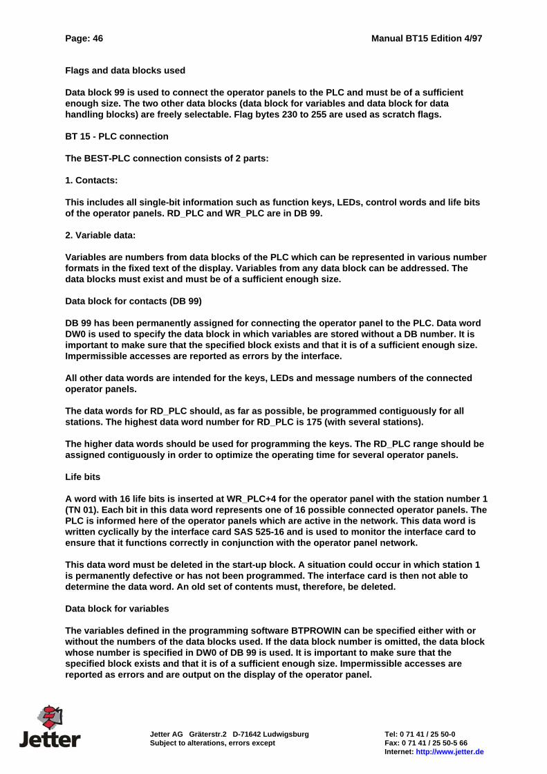
Page: 46 Manual BT15 Edition 4/97
Jetter AG Gräterstr.2 D-71642 Ludwigsburg Tel: 0 71 41 / 25 50-0 Subject to alterations, errors except Fax: 0 71 41 / 25 50-5 66 Internet: http://www.jetter.de
Flags and data blocks used Data block 99 is used to connect the operator panels to the PLC and must be of a sufficient enough size. The two other data blocks (data block for variables and data block for data handling blocks) are freely selectable. Flag bytes 230 to 255 are used as scratch flags. BT 15 - PLC connection The BEST-PLC connection consists of 2 parts: 1. Contacts: This includes all single-bit information such as function keys, LEDs, control words and life bits of the operator panels. RD_PLC and WR_PLC are in DB 99. 2. Variable data: Variables are numbers from data blocks of the PLC which can be represented in various number formats in the fixed text of the display. Variables from any data block can be addressed. The data blocks must exist and must be of a sufficient enough size. Data block for contacts (DB 99) DB 99 has been permanently assigned for connecting the operator panel to the PLC. Data word DW0 is used to specify the data block in which variables are stored without a DB number. It is important to make sure that the specified block exists and that it is of a sufficient enough size. Impermissible accesses are reported as errors by the interface. All other data words are intended for the keys, LEDs and message numbers of the connected operator panels. The data words for RD_PLC should, as far as possible, be programmed contiguously for all stations. The highest data word number for RD_PLC is 175 (with several stations). The higher data words should be used for programming the keys. The RD_PLC range should be assigned contiguously in order to optimize the operating time for several operator panels. Life bits A word with 16 life bits is inserted at WR_PLC+4 for the operator panel with the station number 1 (TN 01). Each bit in this data word represents one of 16 possible connected operator panels. The PLC is informed here of the operator panels which are active in the network. This data word is written cyclically by the interface card SAS 525-16 and is used to monitor the interface card to ensure that it functions correctly in conjunction with the operator panel network. This data word must be deleted in the start-up block. A situation could occur in which station 1 is permanently defective or has not been programmed. The interface card is then not able to determine the data word. An old set of contents must, therefore, be deleted. Data block for variables The variables defined in the programming software BTPROWIN can be specified either with or without the numbers of the data blocks used. If the data block number is omitted, the data block whose number is specified in DW0 of DB 99 is used. It is important to make sure that the specified block exists and that it is of a sufficient enough size. Impermissible accesses are reported as errors and are output on the display of the operator panel.

Manual BT15 Edition 4/97 Page: 47
Tel: 0 71 41 / 25 50-0 Jetter AG Gräterstr.2 D-71642 Ludwigsburg Fax: 0 71 41 / 25 50-5 66 Subject to alterations, errors except Internet: http://www.jetter.de
It is advisable to use the complete definition for global variables whereas the part definition should be reserved for local variables (i.e. those which are only available in the active FB). Adequate support is thus provided for structured programming. Data blocks DB0 and DB1 must not be used because of the special status they have for the PLC. The interface card SAS525-xx uses the data block specified in DB99:DW0 instead.
SKV 485
Distributionboard
Spur lineto operator panel
Trunk lineinput
Trunk lineto next node
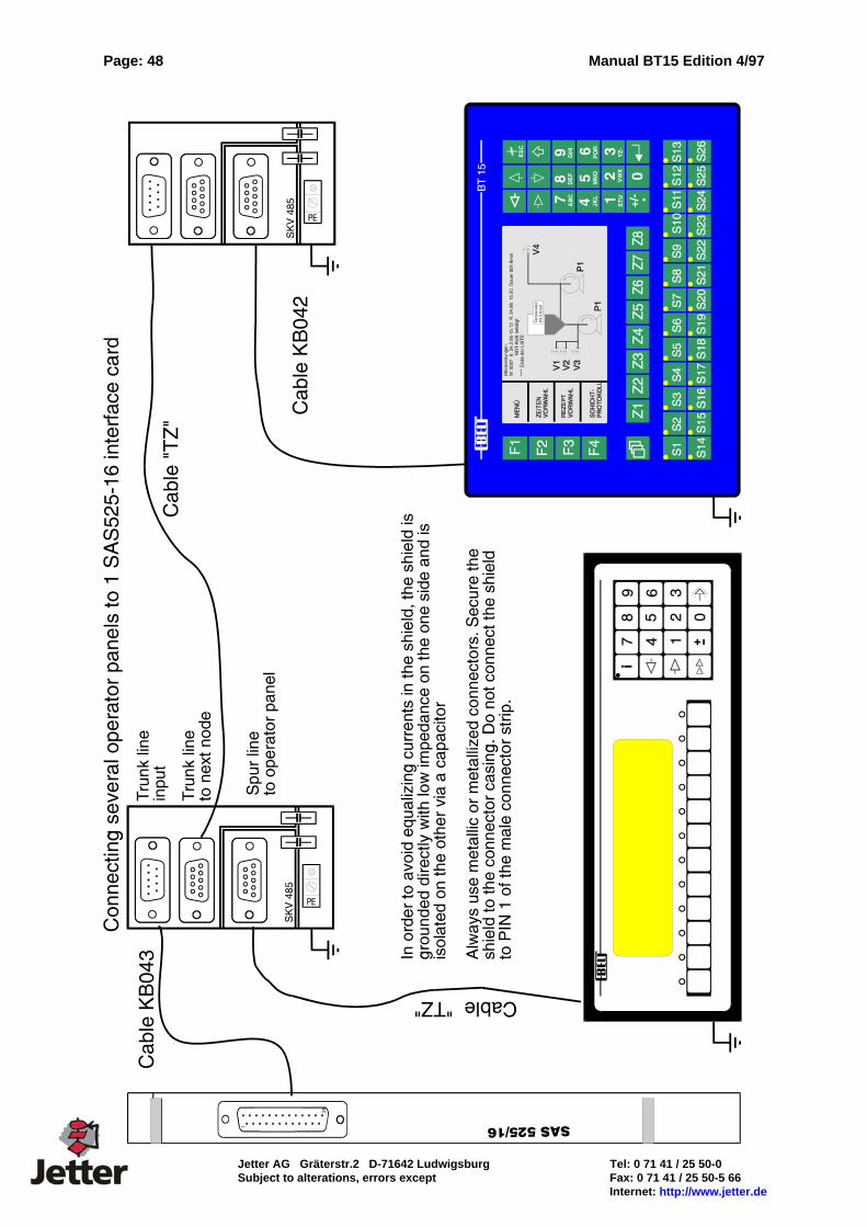
Page: 48 Manual BT15 Edition 4/97
Jetter AG Gräterstr.2 D-71642 Ludwigsburg Tel: 0 71 41 / 25 50-0 Subject to alterations, errors except Fax: 0 71 41 / 25 50-5 66 Internet: http://www.jetter.de

Manual BT15 Edition 4/97 Page: 49
Tel: 0 71 41 / 25 50-0 Jetter AG Gräterstr.2 D-71642 Ludwigsburg Fax: 0 71 41 / 25 50-5 66 Subject to alterations, errors except Internet: http://www.jetter.de
4.8 Mitsubishi FX / FX0 Order Designation BT15 Interface: PLC programming interface (RS232, TTY, RS422/485 &
Programming interface COM1: (RS232)) PLC Driver: MIT_12xxx.btg The RS422 interface (electrically isolated) is used. Interface Setting: Baud Rate: 9600 Baud/ 7 Bit/ PE Installation Set: An installation set is available for starting up the system for the first time. This installation set includes: the programming software BTPROWIN the PLC driver MIT12xxx.btg one connecting cable for PC - BT15 (KB 3++) one connecting cable for (KB040) one connecting cable for (KB041)
Connecting cable:

Page: 50 Manual BT15 Edition 4/97
Jetter AG Gräterstr.2 D-71642 Ludwigsburg Tel: 0 71 41 / 25 50-0 Subject to alterations, errors except Fax: 0 71 41 / 25 50-5 66 Internet: http://www.jetter.de
Data Transfer BT15 <-> PLC The parameterization is performed in the programming software. The variable addresses are specified in the programming software as a number without identifier. Bit flags M0 ... M1023 are also addressed in word-mode. Example: Variable 3000 => M0 ... M15 Variable 3063 => M1008 ... M1023 The following assignment applies: Variable 0 ... 999 D0 ... D999 Variable 1000 ... 1999 D1000 ... D1999 Variable 2000 ... 2199 C0 ... C199 Variable 2200 ... 2255 C200 ... C255 Variable 3000 ... 3095 M0 ... M1535 Variable 4000 ... 4255 T0 ... T255 Variable 8000 ... 8255 D8000 ... D8255 PG-MUX: The FX (25-way connector) requires a jumper between pin 20 and pin 21 for the PG-MUX function. This jumper allows the program memory of the PLC to be written to. If this function is not required, the jumper should be removed for safety reasons in order to avoid accidental or unauthorized program modifications. In addition, the file registers D1000 ... D1999 can not be used without a jumper in the connector. When the PG-MUX is used and the memory allocation in the PLC is modified, the BT15 should perform a restart to cause the memory configuration to be reread from the PLC. If the starting addresses are outside of the ranges, system message 8 with error number 1 is activated.
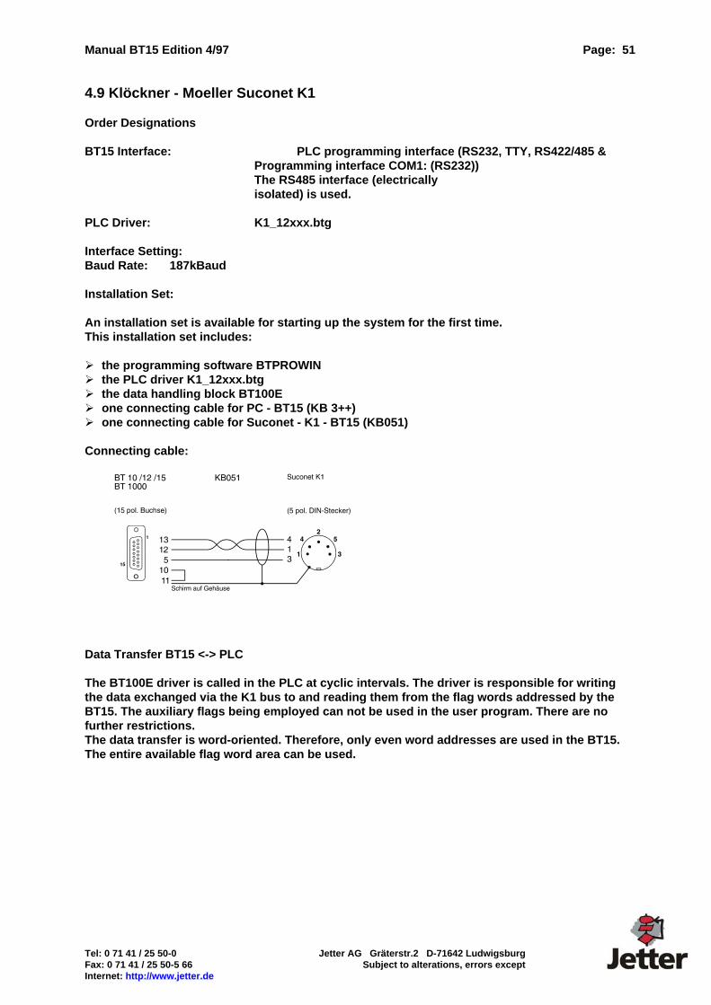
Manual BT15 Edition 4/97 Page: 51
Tel: 0 71 41 / 25 50-0 Jetter AG Gräterstr.2 D-71642 Ludwigsburg Fax: 0 71 41 / 25 50-5 66 Subject to alterations, errors except Internet: http://www.jetter.de
4.9 Klöckner - Moeller Suconet K1 Order Designations BT15 Interface: PLC programming interface (RS232, TTY, RS422/485 &
Programming interface COM1: (RS232)) The RS485 interface (electrically isolated) is used.
PLC Driver: K1_12xxx.btg Interface Setting: Baud Rate: 187kBaud Installation Set: An installation set is available for starting up the system for the first time. This installation set includes: the programming software BTPROWIN the PLC driver K1_12xxx.btg the data handling block BT100E one connecting cable for PC - BT15 (KB 3++) one connecting cable for Suconet - K1 - BT15 (KB051)
Connecting cable:
Data Transfer BT15 <-> PLC The BT100E driver is called in the PLC at cyclic intervals. The driver is responsible for writing the data exchanged via the K1 bus to and reading them from the flag words addressed by the BT15. The auxiliary flags being employed can not be used in the user program. There are no further restrictions. The data transfer is word-oriented. Therefore, only even word addresses are used in the BT15. The entire available flag word area can be used.
Page: 52 Manual BT15 Edition 4/97
Jetter AG Gräterstr.2 D-71642 Ludwigsburg Tel: 0 71 41 / 25 50-0 Subject to alterations, errors except Fax: 0 71 41 / 25 50-5 66 Internet: http://www.jetter.de
4.10 InterBus-S Interface hardware: The IBS interface card is installed in the BT 15 in place of the universal interface card. For the connection to the bus, electrically isolated RS485 drivers are used. The actual bus protocol is handled by the ASIC SUPI-III InterBus-S protocol. A PLC-manufacturer-specific InterBus-S master module which is preferably electrically isolated is required on the controller side. If the master module in the controller is equipped with an 8-wire remote bus interface, the bus can be converted to a 2-wire remote bus with the bus terminal IBS 24 BK/LC2. A data handling block is called in the main program of the controller. This data handling block is parameterized with the locations of the IN and OUT addresses. This data handling block is executed cyclically at least once for each operator panel connected. The data handling block addresses the variables in the data blocks of the PLC. All requests are made from the operator panel which means that programming can be carried out independently of the bus system (Profibus DP, L1, SAS, Modbus). BT15 is integrated in the 2-wire remote bus of the InterBus-S as a slave. The interface module occupies a data width of 4 words (8 bytes) on the InterBus-S. In the controller, each operator panel is represented by means of 8-byte IN data and 8-byte OUT data in the I/O image. A data handling block is available for S5 -115U/CPU945B and S5 -115U/CPU943B. If required, the data handling blocks can be adjusted to suit other CPUs. Parameters: Data Channel Width: 4 Words / 8 Bytes Identcode: 03h (digital remote bus station)
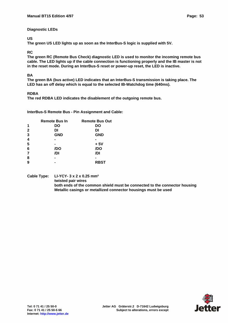
Manual BT15 Edition 4/97 Page: 53
Tel: 0 71 41 / 25 50-0 Jetter AG Gräterstr.2 D-71642 Ludwigsburg Fax: 0 71 41 / 25 50-5 66 Subject to alterations, errors except Internet: http://www.jetter.de
Diagnostic LEDs US The green US LED lights up as soon as the InterBus-S logic is supplied with 5V. RC The green RC (Remote Bus Check) diagnostic LED is used to monitor the incoming remote bus cable. The LED lights up if the cable connection is functioning properly and the IB master is not in the reset mode. During an InterBus-S reset or power-up reset, the LED is inactive. BA The green BA (bus active) LED indicates that an InterBus-S transmission is taking place. The LED has an off delay which is equal to the selected IB-Watchdog time (640ms). RDBA The red RDBA LED indicates the disablement of the outgoing remote bus. InterBus-S Remote Bus - Pin Assignment and Cable: Remote Bus In Remote Bus Out 1 DO DO 2 DI DI 3 GND GND 4 - - 5 - + 5V 6 /DO /DO 7 /DI /DI 8 - - 9 - RBST Cable Type: LI-YCY- 3 x 2 x 0.25 mm² twisted pair wires both ends of the common shield must be connected to the connector housing Metallic casings or metallized connector housings must be used
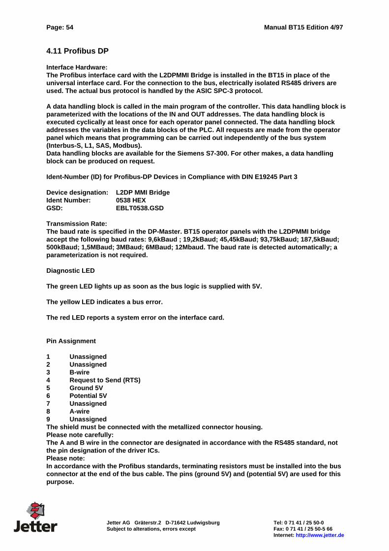
Page: 54 Manual BT15 Edition 4/97
Jetter AG Gräterstr.2 D-71642 Ludwigsburg Tel: 0 71 41 / 25 50-0 Subject to alterations, errors except Fax: 0 71 41 / 25 50-5 66 Internet: http://www.jetter.de
4.11 Profibus DP Interface Hardware: The Profibus interface card with the L2DPMMI Bridge is installed in the BT15 in place of the universal interface card. For the connection to the bus, electrically isolated RS485 drivers are used. The actual bus protocol is handled by the ASIC SPC-3 protocol. A data handling block is called in the main program of the controller. This data handling block is parameterized with the locations of the IN and OUT addresses. The data handling block is executed cyclically at least once for each operator panel connected. The data handling block addresses the variables in the data blocks of the PLC. All requests are made from the operator panel which means that programming can be carried out independently of the bus system (Interbus-S, L1, SAS, Modbus). Data handling blocks are available for the Siemens S7-300. For other makes, a data handling block can be produced on request. Ident-Number (ID) for Profibus-DP Devices in Compliance with DIN E19245 Part 3 Device designation: L2DP MMI Bridge Ident Number: 0538 HEX GSD: EBLT0538.GSD Transmission Rate: The baud rate is specified in the DP-Master. BT15 operator panels with the L2DPMMI bridge accept the following baud rates: 9,6kBaud ; 19,2kBaud; 45,45kBaud; 93,75kBaud; 187,5kBaud; 500kBaud; 1,5MBaud; 3MBaud; 6MBaud; 12Mbaud. The baud rate is detected automatically; a parameterization is not required. Diagnostic LED The green LED lights up as soon as the bus logic is supplied with 5V. The yellow LED indicates a bus error. The red LED reports a system error on the interface card. Pin Assignment 1 Unassigned 2 Unassigned 3 B-wire 4 Request to Send (RTS) 5 Ground 5V 6 Potential 5V 7 Unassigned 8 A-wire 9 Unassigned The shield must be connected with the metallized connector housing. Please note carefully: The A and B wire in the connector are designated in accordance with the RS485 standard, not the pin designation of the driver ICs. Please note: In accordance with the Profibus standards, terminating resistors must be installed into the bus connector at the end of the bus cable. The pins (ground 5V) and (potential 5V) are used for this purpose.

Manual BT15 Edition 4/97 Page: 55
Tel: 0 71 41 / 25 50-0 Jetter AG Gräterstr.2 D-71642 Ludwigsburg Fax: 0 71 41 / 25 50-5 66 Subject to alterations, errors except Internet: http://www.jetter.de
5. System Messages Message:1
Suggested text: Input too large! Maximum:_____________ Number of filler characters in the text: 11 Explanation, further details:...
Message: 2
Suggested text: Input too small! Minimum:_____________ Number of filler characters in the text: 11 Explanation, further details:...
Message: 5
Suggested text: Programming unit occupies PLC interface! Explanation, further details: This message is displayed if the (PLC) programming unit exclusively occupies the communications interface resulting in the BT 15 not being capable of establishing a connection. For example during the download of a program to the PLC....
Message:7
Suggested text: Access level not released Message: 12
Suggested text: Set: __.__ __:__:__ Res: __:__:__ Duration: __:__:__
Please note: Filler characters should not be used. The internal variables I610xx should
be used instead. Explanation: Here, the header for fault messages in the diagnostic memory can be defined. The following internal variables can be used:
Message No.: I61000 Point of time when message is acknowledged
(Priority I61001) (s I61015) (Acknowledgement behavior I61002) (Min I61016) Point of time when message is set (h I61017) s I61003 (Day I61018) Min I61004 (Month I61019) h I61005 (Year I61020) Day I61006 Duration of fault Month I61007 h I61021 Year I61008 min I61022 Point of time when message is reset s I61023 s I61009 Min I61010 h I61011 Day I61012 Month I61013 Year I61014 All variables listed above are represented in the UNS format. The variables in parenthesis are intended for future extensions.
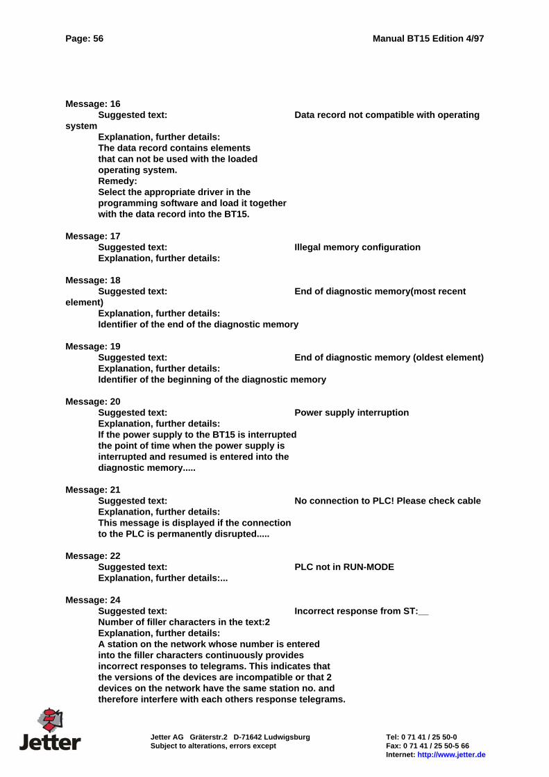
Page: 56 Manual BT15 Edition 4/97
Jetter AG Gräterstr.2 D-71642 Ludwigsburg Tel: 0 71 41 / 25 50-0 Subject to alterations, errors except Fax: 0 71 41 / 25 50-5 66 Internet: http://www.jetter.de
Message: 16
Suggested text: Data record not compatible with operating system
Explanation, further details: The data record contains elements that can not be used with the loaded operating system. Remedy: Select the appropriate driver in the programming software and load it together with the data record into the BT15.
Message: 17 Suggested text: Illegal memory configuration
Explanation, further details:
Message: 18 Suggested text: End of diagnostic memory(most recent
element) Explanation, further details: Identifier of the end of the diagnostic memory
Message: 19 Suggested text: End of diagnostic memory (oldest element) Explanation, further details: Identifier of the beginning of the diagnostic memory
Message: 20 Suggested text: Power supply interruption Explanation, further details: If the power supply to the BT15 is interrupted the point of time when the power supply is interrupted and resumed is entered into the diagnostic memory.....
Message: 21 Suggested text: No connection to PLC! Please check cable Explanation, further details: This message is displayed if the connection to the PLC is permanently disrupted.....
Message: 22 Suggested text: PLC not in RUN-MODE Explanation, further details:...
Message: 24 Suggested text: Incorrect response from ST:__ Number of filler characters in the text:2 Explanation, further details: A station on the network whose number is entered into the filler characters continuously provides incorrect responses to telegrams. This indicates that the versions of the devices are incompatible or that 2 devices on the network have the same station no. and therefore interfere with each others response telegrams.
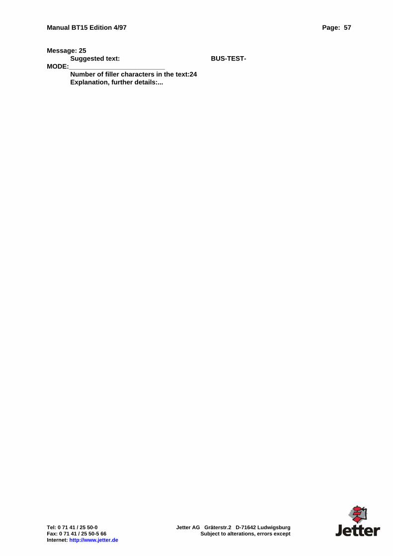
Manual BT15 Edition 4/97 Page: 57
Tel: 0 71 41 / 25 50-0 Jetter AG Gräterstr.2 D-71642 Ludwigsburg Fax: 0 71 41 / 25 50-5 66 Subject to alterations, errors except Internet: http://www.jetter.de
Message: 25 Suggested text: BUS-TEST-
MODE:__________________________ Number of filler characters in the text:24 Explanation, further details:...

Page: 58 Manual BT15 Edition 4/97
Jetter AG Gräterstr.2 D-71642 Ludwigsburg Tel: 0 71 41 / 25 50-0 Subject to alterations, errors except Fax: 0 71 41 / 25 50-5 66 Internet: http://www.jetter.de
Message: 26 Suggested text: ST: __ signals unknown function Number of filler characters in the text:2 Explanation, further details: SAS card version is not compatible with selected driver.
Message: 27 Suggested text: PLC signals error no.: ____
concerning__________ Number of filler characters in the text:4/12 Explanation, further details: The meaning of this error number is PLC-specific. For an explanation see PLC documentation.
Message: 28 Suggested text: Read block too large___ DW as of DW ___
max. DW _____ Number of filler characters in the text: 3/5/5 Explanation, further details: The maximum block size for the SAS525 interface module is exceeded....
Message: 29 Suggested text: No communication set-up with PLC
Type: ________________________ Number of filler characters in the text: 24 Explanation, further details: A connection to the PLC is established however, there is no logic communication. The SAS card version no appears in the filler characters....
Message: 30 Suggested text: Access attempt outside of valid range
to:____________ Cycle Identifier:_ Number of filler characters in the text: 10/1 Explanation, further details:...
Message: 31 Suggested text: Access attempt outside of valid range
by indexed variable to:________Cycle Identifier:_
Number of filler characters in the text: 10/1 Explanation, further details:
Manual BT15 Edition 4/97 Page: 59
Tel: 0 71 41 / 25 50-0 Jetter AG Gräterstr.2 D-71642 Ludwigsburg Fax: 0 71 41 / 25 50-5 66 Subject to alterations, errors except Internet: http://www.jetter.de
6. Internal Variables Internal variables are variables which are not read from the PLC, but are allocated a fixed meaning in the BT15. The following internal variables are available in addition to the internal variables described in conjunction with system message 12. Clock s BCD I60000 Clock min BCD I60001 Clock h BCD I60002 Clock Weekday BCD I60003 (0..6 = Sunday .. Saturday) Clock Day BCD I60004 Clock Month BCD I60005 Clock Year BCD I60006 PLC Communication Error UNS I60011 PLC Communication Cycles UNS I60012 System Switch 13 I60013 Bit 0 Setting of contrast Bit 1 Language Switching 0= 1st Language 1= 2nd Language Bit 2 0=Always Display Fault Message Window
for current Faults 1=always suppress Fault Message Window
Bit 3..15 For Extensions System Switch 14 I60014 Bit 0
Bit 1 Display current Messages in the Diagnostic Memory
Bit 2 Display all Messages in the Diagnostic Memory System Switch 15 I60015 Bit 0..1 PG-Mux, if available for driver 0 = Off, 1 = PG-MUX, 2 =Continuous Connection of PLC - Programming Unit
Page: 60 Manual BT15 Edition 4/97
Jetter AG Gräterstr.2 D-71642 Ludwigsburg Tel: 0 71 41 / 25 50-0 Subject to alterations, errors except Fax: 0 71 41 / 25 50-5 66 Internet: http://www.jetter.de
7. PROGRAMMABLE APPLICATION INTERFACE PAI V1.0 Please note: The programming tool for PAI is optional. If the PAI is used, the BT15 requires memory expansion. Without PAI, the BT15 is controlled by the PLC. The Programmable Application Interface PAI has been developed to relieve the PLC of any OPERATOR CONTROL & MONITORING tasks. This reduces the exchange of data from and to the PLC to the exchange of status and command information. Key functions of the PAI are: Process inputs via keyboard Process inputs via external peripherals such as card reader, bar code reader, scales, etc. Visualize machine states, error messages Link key commands based on machine states Provide data records (parameters) for PLC Provide data records for external peripherals Output MDA and PDA to printer or host computer
These tasks are usually closely linked to the MAN-MACHINE-INTERFACE. It is therefore, advisable to program this accordingly in the operator panel. The commands of the PAI are specifically tailored to these tasks and can thus be used effectively and in a straightforward manner. The amount of work involved in solving the same tasks in the PLC would be disproportionately high. An expensive communications processor is, therefore, not necessary in many cases. 7.1. Memory Allocation between BT and PAI The free RAM is divided into three areas in the programming software BTPROWIN: 1. Diagnostic memory for fault messages 2. Recipe memory (Array A for PAI) 3. Memory for PAI workspace (PAI RAM) In addition, a fixed memory area of 100 words is available for the data transfer between the PAI and BT area in the BT15. The memory capacity is specified in bytes while the allocation of the memory is performed in words (2 bytes). The PAI is capable of directly accessing 3 memory areas: Array A (recipe memory configurable in BTPROWIN) PAI working memory (maximum size configurable in BTPROWIN) BT transfer memory (100 words)
7.1.1 BT Area The BT area comprises 100 words which are addressed by the PAI as BT0 ... BT99. (The BT addresses them as internal variables i60000 .. i60099). Their function is fixed.
Manual BT15 Edition 4/97 Page: 61
Tel: 0 71 41 / 25 50-0 Jetter AG Gräterstr.2 D-71642 Ludwigsburg Fax: 0 71 41 / 25 50-5 66 Subject to alterations, errors except Internet: http://www.jetter.de
7.1.2 PAI Area The PAI-RAM is the actual working memory for the PAI. It is divided into the PAI word addresses ((PAI0 ... PAIn), the dimensioned arrays (arrayB, arrayC, arrayD) and the buffer memories allocated by the peripheral drivers that are used. The compiler computes the total memory space requirement for the PAI and verifies (optional) that sufficient memory space has been reserved in BTPROWIN. The BT accesses the PAI word addresses PAI0 ... PAIn as VA i10000... max. i59999. 7.1.3 Array Memory Areas There are up to 4 arrays (A...D). The programming software BTPROWIN configures array A as a "recipe". Another 3 arrays (B...D) can be configured by the PAI. Array A is configured in accordance with the definitions of the BT project. The PAI adopts this definition without any changes. Arrays B..D are defined in the Init-part of the PAI program. Syntax: DEF(dst,scr1,scr2,scr3) <dst> The array, e.g.. arrayB, arrayC, arrayD <scr1>Number of elements (constants) <scr2> Number of words/elements (constants) <scr3> Array starting address (PAI-N) Example: DEF(B,23,25,PAI50)
Array B consists of 23 elements ("recipes") with 25 words each. The address of the first word in the first element is the address PAI50. From here onwards, the next 512 words are occupied.
7.1.3.1 Access to Arrays The corresponding array index points to the selected element. The word parameter array + n can then be used to access the word in the selected element. Example: LW (AI,10) ; The index register of array A is set to 10
LW (PAI3,A5) ; PAI word address 3 is loaded to element 10 of ; array A with the value from the 5th word
AI = Index register A A = Word n in array A (AI) BI = Index register B Bn = Word n in array B (BI) CI = Index register C Cn = Word n in array C (CI) DI = Index register D Dn = Word n in array D (DI)

Page: 62 Manual BT15 Edition 4/97
Jetter AG Gräterstr.2 D-71642 Ludwigsburg Tel: 0 71 41 / 25 50-0 Subject to alterations, errors except Fax: 0 71 41 / 25 50-5 66 Internet: http://www.jetter.de
7.2. Communication with the PLC The communication with the PLC takes place at three levels: 1. Cyclic data exchange 2. Reading and writing of variables that were defined in message windows and menus 3. Program-controlled reading and writing of data (PAI).
7.2.1 Cyclic Data Exchange with the PLC The PLC addresses WR_PLC and RD_PLD are defined in the programming software BTPROWIN. If an operator panel is connected without PAI, these data blocks have a fixed function (see operator panel manual for description). If the PAI is used, the function of the data can be redefined as desired. WR_PLC The length of the WR_PLC data block (data which are written to the PLC at cyclic intervals) is defined in BT word address BT30. The data block to be transmitted starts from BT word address BT90. In order for the transmission to be performed, changes must have occurred since the previous transmission. The PLC driver performs the check process automatically. The write address in the PLC is defined in the programming software BTPROWIN. RD_PLC The RD_PLC data block is read from the PLC at cyclic intervals and stored in the BT word addresses from address BT70 onwards. The length is defined by the PAI program in BT word address BT30. Flag BT60.0 signals the receipt of an RD_PLC data block. The read address in the PLC is defined in the programming software BTPROWIN. 7.2.2 Reading and Writing Variables Variables are automatically requested from the PLC once they are required on the display. If input variables are written to the PLC, the flag "data transfer in progress" will signal that this process is taking place. 7.2.3 Program-Controlled Reading and Writing of Data (PAI). A program-controlled transfer of data to the PLC can be performed for data from the PAI address range and the defined arrays. See section 7.1.2 7.3 PAI Program The PAI programming language features powerful commands specifically tailored to the requirements of a Man-Machine-Interface (MMI), thereby ideally complementing the PLC.
Manual BT15 Edition 4/97 Page: 63
Tel: 0 71 41 / 25 50-0 Jetter AG Gräterstr.2 D-71642 Ludwigsburg Fax: 0 71 41 / 25 50-5 66 Subject to alterations, errors except Internet: http://www.jetter.de
7.3.1 Language Elements The individual language elements comprise commands, labels, parameters and comments. Comments Comment character is the ";" character. Everything following this character up to the end of the line is treated as a comment. Labels A label is a specific position in the program which, for example, can be jumped to or from which onwards constants are stored. A label must be positioned at the beginning of a line, must be concluded with a colon and has a maximum length of 32 characters. Numbers are not permitted in label names. Labels with fixed definitions (reserved names) Project:[project name] ;the project name is entered here INIT: ;this label precedes all commands, which follow the initialization. ;The part of the program preceded by this label is ;executed only once after BT start-up. LOOP: ;indicates the beginning of the main program which is executed ;at cyclic intervals. Commands The syntax of commands is as follows: Command name <(parameter, parameter,..)> <{further commands}> Certain commands consist of the command name only (e.g. RET). Some commands comprise a block with additional commands enclosed between {} which are executed only if the condition is satisfied (IF..). Word Parameters The following parameters are possible PAI 0...n ;PAI RAM (0....3000) BT0..99 ;BT functions according to the appendix A ..n ;Array according to definition ;I = Index; 1..n = entries according to index nn ;Constant parameter decimal nnh ;Constant parameter hexadecimal (the first character must be a number ;e.g. 0FFFh) nnnnb ;Constant parameter binary Bit Parameters All word parameters except constants with the extension ".B" are possible, with B being the bit position 0..15. e.g. PAI17.3 ;Bit 3 in PAI word address 17
Page: 64 Manual BT15 Edition 4/97
Jetter AG Gräterstr.2 D-71642 Ludwigsburg Tel: 0 71 41 / 25 50-0 Subject to alterations, errors except Fax: 0 71 41 / 25 50-5 66 Internet: http://www.jetter.de
7.4 Structure of a PAI Program The PAI program consists of 3 parts: Project name Initialization Main program (LOOP)
Project Name The project name appears at the beginning of the PAI program and begins with the label "Project:" Example: Project: ["Testprogramm",0] Note: The name ["DEMO",0] is reserved for all BT15 drivers Initialization The initialization starts with the label "INIT:" and is executed one time immediately after the PAI code has been successfully verified. There is no time monitoring. The time required for the execution of the routine can not, however, exceed the watchdog-time (approx. 300ms). The function must be concluded with the command RET()". The "GOTO" command can not be used during the initialization. Main Program (LOOP) The main program starts with the label "LOOP:" and is executed at cyclical intervals. This function must be concluded with the command "RET ()". The execution time is limited to 300ms. 7.5. Commands 7.5.1 "LoadWord", "LW" Syntax: LW (dst, scr) <dst> Target word address (PAI n, BT n, Array n) <scr> Source N (PAI n, BT n, Array n, Constant) Explanation: Loads the contents from word <scr> to the word<dst> (unconditional assignment) 7.5.2 "IFx" Syntax: IFx (scr1, scr2) [{...}] þ =,<,>,>=,<=,<> Type of comparison <scr1> Source word address or bit address (PAI n, BT n, Array n, Constant) <scr2> Source word address or bit address (PAI n, BT n, Array n, Constant) Explanation: Compares <scr1> and <scr2> if the comparison proves to be
"true", the commands of the block in {}or the following command are executed.
Manual BT15 Edition 4/97 Page: 65
Tel: 0 71 41 / 25 50-0 Jetter AG Gräterstr.2 D-71642 Ludwigsburg Fax: 0 71 41 / 25 50-5 66 Subject to alterations, errors except Internet: http://www.jetter.de
7.5.3 "INC" Syntax: INC (dst, scr1, scr2) <dst> the word to be incremented (PAI n, BT n, Array n) <scr1> the lower limit, permitted is: (BT n, PAI n, Constant) <scr2> the upper limit (BT n, PAI n, Constant) Explanation: increments <dst>. If the upper limit is exceeded after the
incrementation (<scr2>), <dst> is set to the lower limit (<scr1>). 7.5.4 "DEC" Syntax: DEC (dst, scr1, scr2) <dst> the word to be decremented (PAI n, BT n, Array n) <scr1> the lower limit (BT n, PAI n, Constant) <scr2> the upper limit (BT n, PAI n, Constant) Explanation: decrements <dst>. If the word falls below the lower limit after the
decrementation (<scr1>), <dst> is set to the upper limit (<scr2>).
7.5.5 "AND" Syntax: AND (dst, scr1, scr2) <dst> Target word address, bit address (PAI n, BT n, Array_n) <scr1> Source word address, bit address (BT n, PAI n, Constant) <scr2> Source word address, bit address (BT n, PAI n, Constant) Explanation: <dst> = <scr1> & <scr2> 7.5.6 "OR" Syntax: OR (dst, scr1, scr2) <dst> Target word address, bit address (PAI n, BT n, Array_n) <scr1> Source word address, bit address (BT n, PAI n, Constant) <scr2> Source word address, bit address (BT n, PAI n, Constant) Explanation: <dst> = <scr1> or <scr2> 7.5.7 "SUB" Syntax: SUB (dst, scr1, scr2) <dst> Target word address (PAI n, BT n, Array n) <scr1> Source word address (BT n, PAI n, Constant) <scr2> Source word address (BT n, PAI n, Constant) Explanation: <dst> = <scr2> - <scr1>

Page: 66 Manual BT15 Edition 4/97
Jetter AG Gräterstr.2 D-71642 Ludwigsburg Tel: 0 71 41 / 25 50-0 Subject to alterations, errors except Fax: 0 71 41 / 25 50-5 66 Internet: http://www.jetter.de
7.5.8 "ADD" Syntax: ADD (dst, scr1, scr2) <dst> Target word address (PAI n, BT n, Array_n) <scr1> Source word address (BT n, PAI n, Constant) <scr2> Source word address (BT n, PAI n, Constant) Explanation: <dst> = <scr1> + <scr2> 7.5.9 "LoadBit","LB" Syntax: LB (dst, scr) <dst> Target bit address (PAI n.b, BT n.b, Array n.b) <scr> Source bit address (PAI n.b, BT n.b, Array n.b) Explanation: Loads <scr> into the <dst> 7.5.10 "SetBit","SB" Syntax: SB (dst) <dst> Target bit address (PAI n.b, BT n.b, Array n.b) Explanation: Unconditional assignment of a "1" to the <dst> 7.5.11 "ResetBit", "RB" Syntax: RB (dst) <dst> Target bit address (PAI n.b, BT n.b, Array n.b) Explanation: Unconditional assignment of a "0" to the <dst> 7.5.12 "IFSET" Syntax: IFSET (scr) [{...}] <scr> Source bit address (PAI n.b, BT n.b, Array n.b) Explanation: If <scr> is "1", the commands of the block in {} or the following command are executed. 7.5.13 "IFRESET" Syntax: IFRESET (scr) [{...}] <scr> Source bit address (PAI n.b, BT n.b, Array n.b) Explanation: If <scr> is "0" , the commands in the
block in {} or the following command are executed. 7.5.14 "IFPLU" Syntax: IFPLU (scr1,scr2) [{...}] <scr1> Source bit address (PAI n.b, BT n.b, Array n.b) <scr2> Source bit address ((auxiliary bit) PAI n.b) Explanation: If <scr1> has a modification from "0" to "1", the commands in the
block in {} or the following command are executed. The auxiliary bit can not be used more than once.
Manual BT15 Edition 4/97 Page: 67
Tel: 0 71 41 / 25 50-0 Jetter AG Gräterstr.2 D-71642 Ludwigsburg Fax: 0 71 41 / 25 50-5 66 Subject to alterations, errors except Internet: http://www.jetter.de
7.5.15 "IFPLD" Syntax: IFPLD (scr1,scr2) [{...}] <scr1> Source bit address (PAI n.b, BT n.b, Array n.b) <scr2> Source bit address ((auxiliary bit) PAI n.b)) Explanation: If <scr1> has a modification from "1" to "0", the commands in the block in {} or the following command are executed. 7.5.20 "RETURN","RET" Syntax: RET () Explanation: Concludes a function procedure call 7.5.21 "GOTO","GO" Syntax: GO (label) Explanation: Jump to <label> 7.5.22 "COPY" Syntax: COPY(dst,scr1,scr2) <dst> Target word address (PAI n, BT n, Array n ) <scr1> Source word address (PAI n, BT n, Array n) <scr2> Number of words (PAI n, BT n, Constant) Explanation: Copies the block (Length =<scr2>) from <scr1> to <dst> 7.5.23 "DEF" Syntax: DEF(dst,scr1,scr2,scr3) <dst> The array, e.g. array B, array C, array D <scr1> Number of recipes (PAI n, BT n, Constant) <scr2> Number of words/recipe (PAI n, BT n, Constant) <scr3> Array starting address (PAI n) 7.5.24 "PLCTR" Syntax: PLCTR(dst,scr1,scr2,scr3) <dst> Target word address (PAI n, BT n, Array n, PLC address) <scr1> Source word address (PAI n, BT n, Array n, PLC address) <scr2> Number of words (PAI n, BT n, Constant) <scr3> Coordination flag (bit address in PAI n, BT n) 7.5.25 "CANTR" Syntax: CANTR(dst,scr1,scr2,scr3) <dst> Target word address (PAI n, BT n, Array n, CAN identifier) <scr1> Source word address (PAI n, BT n, Array n, CAN identifier) <scr2> Number of words (PAI n, BT n, Constant) <scr3> Coordination flag (bit address in PAI n, BT n)
Page: 68 Manual BT15 Edition 4/97
Jetter AG Gräterstr.2 D-71642 Ludwigsburg Tel: 0 71 41 / 25 50-0 Subject to alterations, errors except Fax: 0 71 41 / 25 50-5 66 Internet: http://www.jetter.de
8. PAI Compiler The Programming software BTPROWIN comprises an editor which is used to create the PAI source program. The optional PAI software is required to activate this function. Compiling and loading is a separate function of the programming software. The compiler is composed of the actual compiler core and the compiler configuration file "TLCS.CFG". The "*.CFG" file is created in a processor-specific manner (in the operator panel) and contains information on commands and parameters that can be used. 8.1 Download and Integration The binary file stored by the compiler is transferred to the BT by the BTPROWN programming system (Vers 2.5 and higher). In the BT15 the data are stored in the flash memory. During a restart, the BT15 verifies the PAI code for correctness (check sum). If an error is detected, the system stops and displays an error message.

Manual BT15 Edition 4/97 Page: 69
Tel: 0 71 41 / 25 50-0 Jetter AG Gräterstr.2 D-71642 Ludwigsburg Fax: 0 71 41 / 25 50-5 66 Subject to alterations, errors except Internet: http://www.jetter.de
9. BT / PAI Addresses BT 0 i60000 Time s BCD (read only) BT 1 i60001 Time min BCD (read only) BT 2 i60002 Time Hr. BCD (read only) BT 3 i60003 Time Weekday BCD (read only) BT 4 i60004 Time Day BCD (read only) BT 5 i60005 Time Month BCD (read only) BT 6 i60006 Time Year BCD (read only) BT 7..10 PLC-specific settings according to interface module BT 11 i60011 Number of incorrect PLC cycles since reset BT 12 i60012 Number of initiated PLC cycles since previous reset BT 13 i60013 System switch BT 13.0 i60013.0 Setting of contrast BT 13.1 i60013.1 0= Language 1 / 1= Language 2 BT 13.2 i60013.2 1= do not display fault messages in background graphics BT 14 i60014 current execution time of PAI program BT 15 i60015 Maximum execution time of PAI program BT16..BT19 Reserve BT 20 i60020 Control word
Bit 0 .. 3 Numerical keys BT 20.4 i60020.4 Shift key BT 20.5 i60020.5 BT 20.6 i60020.6 Return key BT 20.7 i60020.7 Life bit BT 20.8 i60020.8 ESC key BT 20.9 i60020.9 Arrow left BT 20.10 i60020.10 Arrow right BT 20.11 i60020.11 Arrow up BT 20.12 i60020.12 Arrow down BT 20.15 i60020.15 Min. 1 fault message active BT 21 i60021 Bit 0 .. 9 / currently active menu element BT 21.10 i60021.10 Menu function key F6 BT 21.11 i60021.11 Menu function key F5 BT 21.12 i60021.12 Menu function key F4 BT 21.13 i60021.13 Menu function key F3 BT 21.14 i60021.14 Menu function key F2 BT 21.15 i60021.15 Menu function key F1 BT 22.0 i60022.0 S16 BT 22.1 i60022.1 S15 BT 22.2 i60022.2 S14 BT 22.3 i60022.3 S13 BT 22.4 i60022.4 S12 BT 22.5 i60022.5 S11 BT 22.6 i60022.6 S10 BT 22.7 i60022.7 S9 BT 22.8 i60022.8 S8 BT 22.9 i60022.9 S7 BT 22.10 i60022.10 S6 BT 22.11 i60022.11 S5 BT 22.12 i60022.12 S4 BT 22.13 i60022.13 S3 BT 22.14 i60022.14 S2
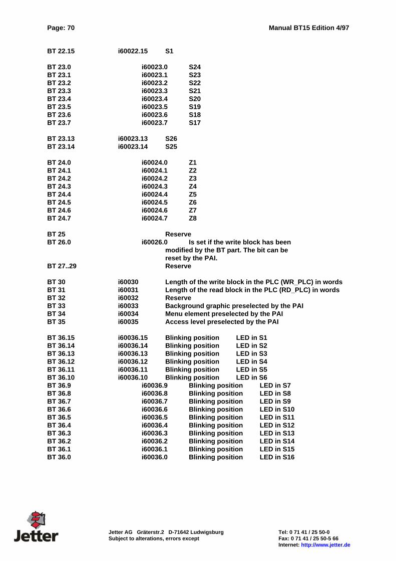
Page: 70 Manual BT15 Edition 4/97
Jetter AG Gräterstr.2 D-71642 Ludwigsburg Tel: 0 71 41 / 25 50-0 Subject to alterations, errors except Fax: 0 71 41 / 25 50-5 66 Internet: http://www.jetter.de
BT 22.15 i60022.15 S1 BT 23.0 i60023.0 S24 BT 23.1 i60023.1 S23 BT 23.2 i60023.2 S22 BT 23.3 i60023.3 S21 BT 23.4 i60023.4 S20 BT 23.5 i60023.5 S19 BT 23.6 i60023.6 S18 BT 23.7 i60023.7 S17 BT 23.13 i60023.13 S26 BT 23.14 i60023.14 S25 BT 24.0 i60024.0 Z1 BT 24.1 i60024.1 Z2 BT 24.2 i60024.2 Z3 BT 24.3 i60024.3 Z4 BT 24.4 i60024.4 Z5 BT 24.5 i60024.5 Z6 BT 24.6 i60024.6 Z7 BT 24.7 i60024.7 Z8 BT 25 Reserve BT 26.0 i60026.0 Is set if the write block has been modified by the BT part. The bit can be reset by the PAI. BT 27..29 Reserve BT 30 i60030 Length of the write block in the PLC (WR_PLC) in words BT 31 i60031 Length of the read block in the PLC (RD_PLC) in words BT 32 i60032 Reserve BT 33 i60033 Background graphic preselected by the PAI BT 34 i60034 Menu element preselected by the PAI BT 35 i60035 Access level preselected by the PAI BT 36.15 i60036.15 Blinking position LED in S1 BT 36.14 i60036.14 Blinking position LED in S2 BT 36.13 i60036.13 Blinking position LED in S3 BT 36.12 i60036.12 Blinking position LED in S4 BT 36.11 i60036.11 Blinking position LED in S5 BT 36.10 i60036.10 Blinking position LED in S6 BT 36.9 i60036.9 Blinking position LED in S7 BT 36.8 i60036.8 Blinking position LED in S8 BT 36.7 i60036.7 Blinking position LED in S9 BT 36.6 i60036.6 Blinking position LED in S10 BT 36.5 i60036.5 Blinking position LED in S11 BT 36.4 i60036.4 Blinking position LED in S12 BT 36.3 i60036.3 Blinking position LED in S13 BT 36.2 i60036.2 Blinking position LED in S14 BT 36.1 i60036.1 Blinking position LED in S15 BT 36.0 i60036.0 Blinking position LED in S16
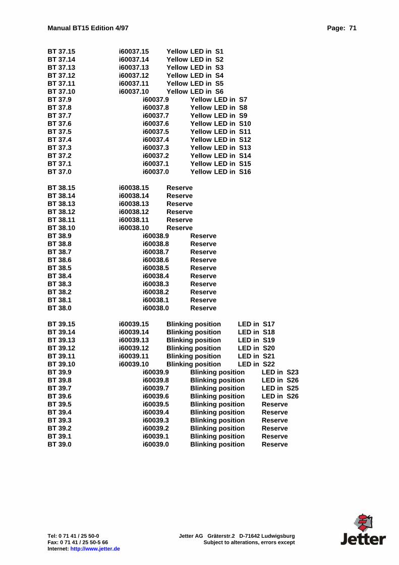
Manual BT15 Edition 4/97 Page: 71
Tel: 0 71 41 / 25 50-0 Jetter AG Gräterstr.2 D-71642 Ludwigsburg Fax: 0 71 41 / 25 50-5 66 Subject to alterations, errors except Internet: http://www.jetter.de
BT 37.15 i60037.15 Yellow LED in S1 BT 37.14 i60037.14 Yellow LED in S2 BT 37.13 i60037.13 Yellow LED in S3 BT 37.12 i60037.12 Yellow LED in S4 BT 37.11 i60037.11 Yellow LED in S5 BT 37.10 i60037.10 Yellow LED in S6 BT 37.9 i60037.9 Yellow LED in S7 BT 37.8 i60037.8 Yellow LED in S8 BT 37.7 i60037.7 Yellow LED in S9 BT 37.6 i60037.6 Yellow LED in S10 BT 37.5 i60037.5 Yellow LED in S11 BT 37.4 i60037.4 Yellow LED in S12 BT 37.3 i60037.3 Yellow LED in S13 BT 37.2 i60037.2 Yellow LED in S14 BT 37.1 i60037.1 Yellow LED in S15 BT 37.0 i60037.0 Yellow LED in S16 BT 38.15 i60038.15 Reserve BT 38.14 i60038.14 Reserve BT 38.13 i60038.13 Reserve BT 38.12 i60038.12 Reserve BT 38.11 i60038.11 Reserve BT 38.10 i60038.10 Reserve BT 38.9 i60038.9 Reserve BT 38.8 i60038.8 Reserve BT 38.7 i60038.7 Reserve BT 38.6 i60038.6 Reserve BT 38.5 i60038.5 Reserve BT 38.4 i60038.4 Reserve BT 38.3 i60038.3 Reserve BT 38.2 i60038.2 Reserve BT 38.1 i60038.1 Reserve BT 38.0 i60038.0 Reserve BT 39.15 i60039.15 Blinking position LED in S17 BT 39.14 i60039.14 Blinking position LED in S18 BT 39.13 i60039.13 Blinking position LED in S19 BT 39.12 i60039.12 Blinking position LED in S20 BT 39.11 i60039.11 Blinking position LED in S21 BT 39.10 i60039.10 Blinking position LED in S22 BT 39.9 i60039.9 Blinking position LED in S23 BT 39.8 i60039.8 Blinking position LED in S26 BT 39.7 i60039.7 Blinking position LED in S25 BT 39.6 i60039.6 Blinking position LED in S26 BT 39.5 i60039.5 Blinking position Reserve BT 39.4 i60039.4 Blinking position Reserve BT 39.3 i60039.3 Blinking position Reserve BT 39.2 i60039.2 Blinking position Reserve BT 39.1 i60039.1 Blinking position Reserve BT 39.0 i60039.0 Blinking position Reserve
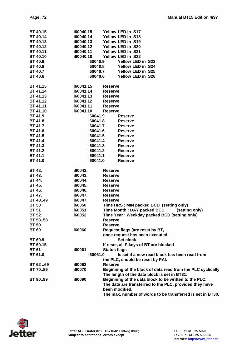
Page: 72 Manual BT15 Edition 4/97
Jetter AG Gräterstr.2 D-71642 Ludwigsburg Tel: 0 71 41 / 25 50-0 Subject to alterations, errors except Fax: 0 71 41 / 25 50-5 66 Internet: http://www.jetter.de
BT 40.15 i60040.15 Yellow LED in S17 BT 40.14 i60040.14 Yellow LED in S18 BT 40.13 i60040.13 Yellow LED in S19 BT 40.12 i60040.12 Yellow LED in S20 BT 40.11 i60040.11 Yellow LED in S21 BT 40.10 i60040.10 Yellow LED in S22 BT 40.9 i60040.9 Yellow LED in S23 BT 40.8 i60040.8 Yellow LED in S24 BT 40.7 i60040.7 Yellow LED in S25 BT 40.6 i60040.6 Yellow LED in S26 BT 41.15 i60041.15 Reserve BT 41.14 i60041.14 Reserve BT 41.13 i60041.13 Reserve BT 41.12 i60041.12 Reserve BT 41.11 i60041.11 Reserve BT 41.10 i60041.10 Reserve BT 41.9 i60041.9 Reserve BT 41.8 i60041.8 Reserve BT 41.7 i60041.7 Reserve BT 41.6 i60041.6 Reserve BT 41.5 i60041.5 Reserve BT 41.4 i60041.4 Reserve BT 41.3 i60041.3 Reserve BT 41.2 i60041.2 Reserve BT 41.1 i60041.1 Reserve BT 41.0 i60041.0 Reserve BT 42. i60042. Reserve BT 43. i60043. Reserve BT 44. i60044. Reserve BT 45. i60045. Reserve BT 46. i60046. Reserve BT 47. i60047. Reserve BT 48..49 i60047. Reserve BT 50 i60050 Time HRS : MIN packed BCD (setting only) BT 51 i60051 Time Month : DAY packed BCD (setting only) BT 52 i60052 Time Year : Weekday packed BCD (setting only) BT 53..58 Reserve BT 59 Reserve BT 60 i60060 Request flags (are reset by BT,
once request has been executed. BT 60.9 Set clock BT 60.15 If reset, all F-keys of BT are blocked BT 61 i60061 Status flags BT 61.0 i60061.0 Is set if a new read block has been read from
the PLC, should be reset by PAI. BT 62 ..69 i60062 Reserve BT 70..89 i60070 Beginning of the block of data read from the PLC cyclically
The length of the data block is set in BT31. BT 90..99 i60090 Beginning of the data block to be written to the PLC.
The data are transferred to the PLC, provided they have been modified. The max. number of words to be transferred is set in BT30.