manual diffusion cell - files.hansonresearch.com · manual diffusion cell operation manual...
TRANSCRIPT

Manual Diffusion Cell Operation Manual
58-001-802 REV. B
DATE: 19Sep2012
Hanson Research Corporation
9810 Variel Avenue Chatsworth, CA 91311 USA (800) 821-8165 (818) 882-7266 FAX (818) 882-9470 www.hansonresearch.com
2012 Hanson Research Corporation.
This product is covered under one or more of the following US Patents: 3,572,648 4,108,602 4,274,286 5,198,109 5,296,139 5,639,953 5,639,974 5,682,001 6,006,777 6,076,410 6,422,098 Des.377,152 Des.424,458 & Other Patents Pending.

Table of Contents
i
Table of Contents Page Section One – Safety Considerations .............................................................................1-1
1.1 General .............................................................................................................1-1 1.2 Warning Signs ..................................................................................................1-1 1.3 Canadian Emissions Notice ..............................................................................1-2
Section Two - Introduction ..............................................................................................2-1
2.1 General Information ..........................................................................................2-1 Section Three - Specifications ........................................................................................3-1 Section Four - Installation ...............................................................................................4-1
4.1 Location ............................................................................................................4-1 4.2 Space Requirements ........................................................................................4-1 4.3 Electrical Requirements ....................................................................................4-2 4.4 Unpacking and Inspection .................................................................................4-3 4.5 Identification ......................................................................................................4-4 4.6 Installation and Electrical Connections ..............................................................4-7 4.7 Bath Circulator Connections .............................................................................4-9 4.8 Jacketed Beaker ...............................................................................................4-9 4.9 Flow Indicator ...................................................................................................4-9 4.10 Start Up Evaluation ......................................................................................... 4-10
Section Five – Operating Instructions, Programming ...................................................5-1
5.1 Speed Control ...................................................................................................5-1 5.2 Bath Circulator ..................................................................................................5-1
Section Six – Operation and Setting Up .........................................................................6-1
6.1 Overview ...........................................................................................................6-1 6.2 Cell Preparation ................................................................................................6-2 6.3 Membrane Preparation .....................................................................................6-3 6.4 Deaeration Technique .......................................................................................6-4 6.5 Variomag Control ..............................................................................................6-5 6.6 Bath Circulator ..................................................................................................6-6 6.7 Starting and Running a Test .............................................................................6-7 6.8 Clean Up ...........................................................................................................6-8
Section Seven – Troubleshooting ...................................................................................7-1
7.1 Contacting Hanson Research Corporation for Technical Support .....................7-1 7.2 Liquid Flow........................................................................................................7-1
Section Eight – Maintenance and Calibration ................................................................8-1
8.1 Maintenance Schedule .....................................................................................8-1 8.2 General Cleaning ..............................................................................................8-1 8.3 Cell Volume Evaluation .....................................................................................8-2 8.4 Syringe Volume Evaluation ...............................................................................8-2
Section Nine – Moving and Storage ................................................................................9-1 Section Ten – Parts, Supplies and Accessories .......................................................... 10-1

Table of Contents
ii
Section Eleven – Sales and Service Offices ................................................................. 11-1 Section Twelve - Warranty ............................................................................................. 12-1 What’s New Revision B (Sep 2012)
Section 3 – Specifications
Updated with information regarding new stir control and water bath Section 4 – Installation
Updated with information regarding new stir control and water bath Section 5 – Operating Instructions Updated 5.2 with appropriate speed setting for new waterbath Section 6 – Operation and Setup Updated section 6.4 with correct settings for new stir control Updated section 6.5 with correct settings for new waterbath Section 10 – Parts, Supplies, and Accessories Corrected part numbers
Revision A (Sep 2001) Initial Release

Section 1 Safety Considerations
1 - 1
Section One - Safety Considerations 1.1 General
1. The Installation Category (Overvoltage Category) for this instrument
is Level II. The Level II category pertains to equipment that receives its electrical power from a local level, such as an electrical wall outlet.
2. This instrument and all accessories must be connected to a
grounded electrical outlet. 3. Never work on the electrical components in the system while there
is power to the unit. Disconnect power to service instrument. 4. Review all safety and environmental precautions pertaining to any
chemicals that are to be used in conjunction with this equipment. 1.2 Safety checks, warning signs and other symbols
For your own safety, you must observe the following safety checks and warning signs. These signs indicate a possible source of danger. They also provide information on what to do to avoid danger.
Sign Location and/or Reason
Safety Warning
N/A Attention: This is a highly sensitive instrument. Read this operator’s guide before using the Manual Test System. When you use the system, follow generally accepted procedures for quality control and methods development.
N/A Attention: Changes or modifications to the units that make up the Hanson Manual Test System that are not expressly approved by the party responsible for compliance could void the user’s authority to operate the equipment.
N/A Attention: This equipment has been tested and found to comply with the limits for a Class A digital device, pursuant to Part 15 of the FCC rules. These limits are designed to provide reasonable protection against harmful interference when the equipment is operated in a commercial environment. This equipment generates, uses, and can radiate radio frequency energy, and, if not installed and used in accordance with the instruction manual, may cause harmful interference to radio communications. Operation of this equipment in a residential area is likely to cause harmful interference, in which case you must correct the interference at your own expense. Shielded cables must be used with this unit to ensure compliance with the Class A FCC limits.
Section 1 Safety Considerations
1 - 2
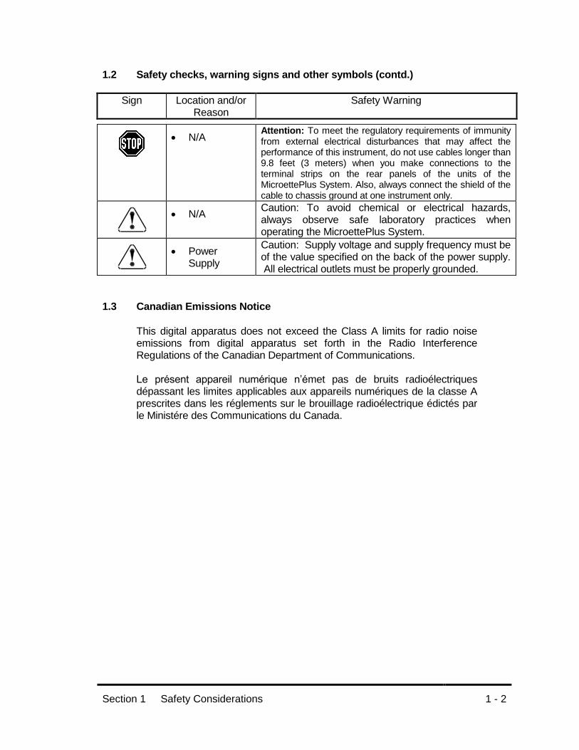
1.2 Safety checks, warning signs and other symbols (contd.)
Sign Location and/or Reason
Safety Warning
N/A Attention: To meet the regulatory requirements of immunity from external electrical disturbances that may affect the performance of this instrument, do not use cables longer than 9.8 feet (3 meters) when you make connections to the terminal strips on the rear panels of the units of the MicroettePlus System. Also, always connect the shield of the cable to chassis ground at one instrument only.
N/A Caution: To avoid chemical or electrical hazards, always observe safe laboratory practices when operating the MicroettePlus System.
Power Supply
Caution: Supply voltage and supply frequency must be of the value specified on the back of the power supply. All electrical outlets must be properly grounded.
1.3 Canadian Emissions Notice
This digital apparatus does not exceed the Class A limits for radio noise emissions from digital apparatus set forth in the Radio Interference Regulations of the Canadian Department of Communications. Le présent appareil numérique n’émet pas de bruits radioélectriques dépassant les limites applicables aux appareils numériques de la classe A prescrites dans les réglements sur le brouillage radioélectrique édictés par le Ministére des Communications du Canada.

Section 2 Introduction
2 - 1
Section Two - Introduction
2.1 General Information It is recommended to read the entire manual before installing or operating this equipment. The Manual Test System samples are collected (by means of precision syringe and HPLC vial manually). The media enters the cell at the bottom, the sample within the cell is then pushed out the sampling port (top port) of the cell, with some sent to waste and the remainder collected in the HPLC vial. The basic system consists of one group of 6 cells mounted on a stand. The stand has a magnetic stirring drive installed in it. The stirring drive is controlled by the stirring control, which is used to set the speed at which the magnets in the cells rotate. Diffusion cell temperature control is used by means of a bath circulator, which is connected to the cells. The bath circulator flows through each cell and then through the jacketed beaker containing replacement solution. Normally cell temperature is maintained at about 32C.

Section 3 Specifications
3 - 1
Section Three - Specifications Weight:
Cell Drive Control:............................................................................ 2 kg (4.4 lb.) Cell Drive: ...................................................................................... 8.2 kg (18 lb.) Heating Circulators (PolyScience MIXcontrol): .............................. 7.2 kg (16 lb.)
Size: Heating Circulator (PolyScience AP07H200) Width: ........................................................................................... 20 CM (8.0 in.) Depth: ......................................................................................... 38 CM (15.0 in.) Height: ........................................................................................ 33 CM (13.0 in.)
Size: Cell Stand with Drive and Control Width: ......................................................................................... 25 CM (10.0 in.) Depth: ......................................................................................... 61 CM (24.0 in.) Height: .......................................................................................... 20 CM (8.0 in.)
Overall Bench Top Size: (recommendations)
6 Cells Width: ............................................................................................ 76 CM (30 in.) Depth: ............................................................................................ 76 CM (30 in.)
System Electrical Requirements: Voltages:................................................................. 120 VAC or 240 VAC ± 10% Grounding: ...................................................................... Earth Ground Required
Electrical: Speed Control Voltage: ........................................................................................ 100 - 240 VAC Frequency:............................................................................................. 50/60 Hz Power Dissipation: ..................................................................... (0.8 A) 96 Watts Phase: ........................................................................................................ single
Electrical: Heating Circulator Voltage: ................................................ 120 VAC or 230 VAC ± 10%, Grounded Frequency:............................................................................................. 50/60 Hz Power Dissipation: ................................................................. (8.8 A) 1012 Watts Phase: ........................................................................................................ single
Environment: Ambient Temperature Range: .................. 8-10 °C below operating temperature Maximum Humidity: ................................................................................... < 85%
Materials, Wet: Syringes: ................................................................ Borosilicate Glass and Teflon Cells and Tops: ...................................................... Borosilicate Glass and Teflon Injection Needles: ................................... Polycarbonate and 304 Stainless Steel Helix: ............................................................................................. Stainless Steel
Sampling:

Section 3 Specifications
3 - 2
Septum: .................................................................................. Pre-Cut Type Only Speed Control (Manufactures Specifications MIXcontrol):
Stirring Power: .................................10 to 100% of nominal power in steps of 10 Nominal Power (VA): ........................................................................................40 Rotation Speed Range (1/min): ...................................... 100 (+30) to 2000 (-50) Rotational Speed Constancy (%): ................................................................ +/- 3
Bath Circulator (Manufactures Specifications AP07H200):
Temperature Range: ....................................................... Ambient +5 to 200 C *Temperature Stability: ......................................................................... +/- 0.1 C Readout ........................................................................................................ LCD Readout Accuracy .............................................................................. +/- 0.25 C Pump ........................................................................................................ Duplex Pump Flow Rate (pressure) @ 120 V, 60 Hz ......................... 11 to 24 liters/min. Pump Flow Rate (suction) ........................................................ 8 to 18 liters/min. RS232 Interface ............................................................................................ Yes
*= Can be effected by viscosity, specific heat of the fluid, external heat loss, and ambient temperature.

Section 4 Installation
4 - 1
Section Four - Installation 4.1 Location
Environment The Manual Test System should be located away from heating and cooling vents, and away from windows and direct sunlight. The bench should be flat and capable of supporting the complete system weight; see section 3 for requirements.
4.2 Space Requirements
Figure 4-1 Typical System Layout
The Manual Test System is designed to be placed on a standard laboratory bench that is at least 76 cm (30 inches) deep and 61 cm (24 inches) wide, although a bench width of 76 cm (30 inches) is suggested. The system requires clearance above the bench of at least 76 cm (30 inches) although it is recommended to not have anything over the equipment. The laboratory bench should be level and flat.
MEDIASOURCE
SPEEDCONTROL
DRIVE ANDSTAND
TEMPERATURECONTROL
Section 4 Installation
4 - 2
4.3 Electrical Requirements
The complete system will require 2 electrical outlets. Each of the components power cables are 2.5 meters (8 feet) long.
Note: Power cords may need to be replaced for some countries’ power outlet configuration. Ensure replacement power cord or power outlet adapter is approved and properly rated for use on these products; see section 3 for requirements. Never use an adapter or any other electrical connection device that removes the ground connection.
The Manual Test System requires a single grounded electrical outlet, within 2.5 meters (8 feet) of the location of the system. The Manual Test System is available in one configuration, 100V through 240V. The voltage is automatically set when voltage is supplied to the external power supply.
The Stirring Control and Drive requires a three prong electrical outlet, within 2.5 meters (8 feet) of the location of the system. The stirring control is available in one configuration, 100V through 240V. The voltage is automatically set when voltage is supplied to the external power supply. Read the manufactures operation manual before installing this product. The Heating Circulator is available in two configurations, 115V and 230V. The Heating Circulator is connected directly into a power outlet. Make sure to check the nameplate on the back panel to ensure the unit is the correct voltage. Read the manufactures operation manual before installing this product.

Section 4 Installation
4 - 3
4.4 Unpacking and Inspection
The Manual Test System is shipped in one or more boxes. The shipping boxes were specifically designed to provide maximum shipping protection and to facilitate unpacking.
1. The Manual Test System, spare parts kits and accessories are
packed in individual custom fit enclosures and then placed into crate size boxes. Carefully unpack your Manual Test System from its shipping cartons.
2. Check the contents of the carton against the shipping list to be
sure that you have unpacked the entire shipment.
3. Inspect each unit for damage, and if any is evident, inform the shipping company immediately. It is also a good idea to save the shipping cartons in case of damage. Hanson Research Corporation insures all shipments through the shipping company, but is not responsible for shipping damages.
To Unpack
1. Move package close to final destination. 2. Cut and remove any straps. 3. Open box, taking care not to damage box. 4. Remove instrument(s) and accessories from box while checking
against packing slip to ensure all parts have been removed. Do not throw boxes away until it has been determined that all items have been removed.
5. Reassemble empty box and store for possible future use, if desired.

Section 4 Installation
4 - 4
4.5 Identification
Throughout this manual, reference is made to various components by name. Figures are provided to assist in the visual identification of these components.
Figure 4-2 Diffusion Cell
Figure 4-3 Drive
Figure 4-4 Stand
Section 4 Installation
4 - 5
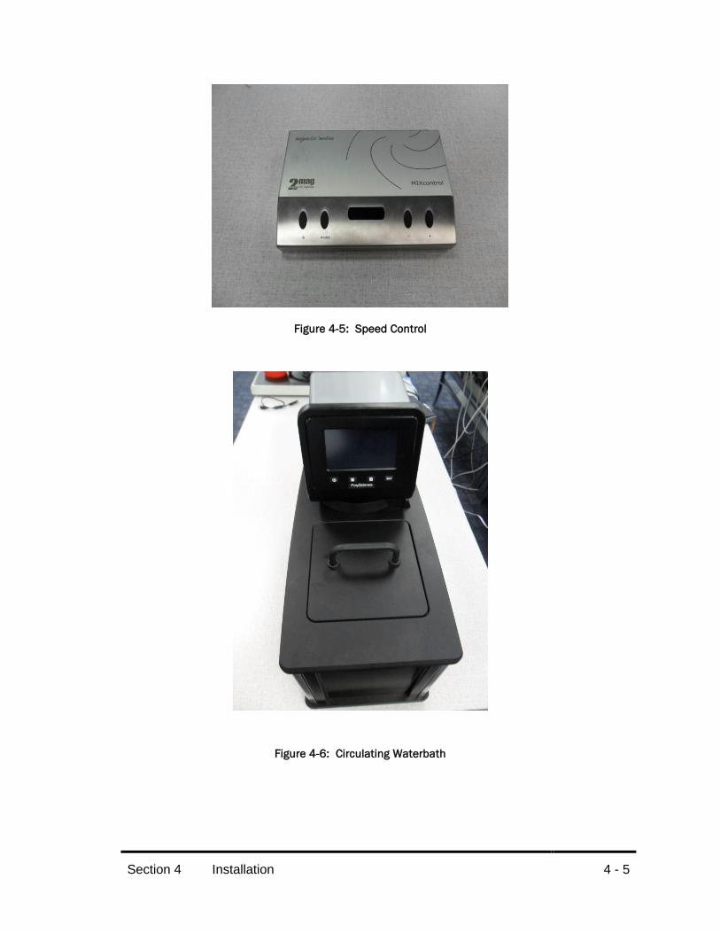
Figure 4-5: Speed Control
Figure 4-6: Circulating Waterbath

Section 4 Installation
4 - 6
Figure 4-7 Jacketed Media Beaker

Section 4 Installation
4 - 7
4.6 Installation and Electrical Connections
1. After removing the instrument from the box, remove all other shipping materials.
2. Visually inspect the instrument(s) for damage or missing parts.
Make note of any discrepancies and contact Hanson Research immediately.
3. Remove any strapping or tape holding the unit for shipping. 4. Clean the unit as necessary to remove any packing debris. 5. Visually inspect all electrical and liquid connections for damage. 6. Review operation manuals.
CAUTION The unit should not be plugged in until installed per
instructions below.
First decide the overall location of the complete system. It is best if there is access to the back of the system, this will help in installing and connecting the system. Place all components on the bench to start; this will aid in overall layout before connections are made. For countries that have different electrical outlets than those that are supplied, the plugs will require changing to that countries power outlet style.
1. Bath Circulator
The bath circulator should be placed to the far right or far left side of the allocated area. See bath manufacturer’s installation instructions for proper bath installation and startup.
2. Cell Drive, Stand and Stirring Control
Insert the stirring drive into the metal stand, making sure the cord is facing the back. Align the dots on the drive to the holes in the stand. Insert the plug from the Cell Drive into the corresponding socket on the back of the Stirring Control and turn the ring until snug. Insert the plug from the power supply into the corresponding socket on the back of the Stirring Control. Insert one end of the power cord into the power supply. Insert the other end into an electrical outlet.
Section 4 Installation
4 - 8
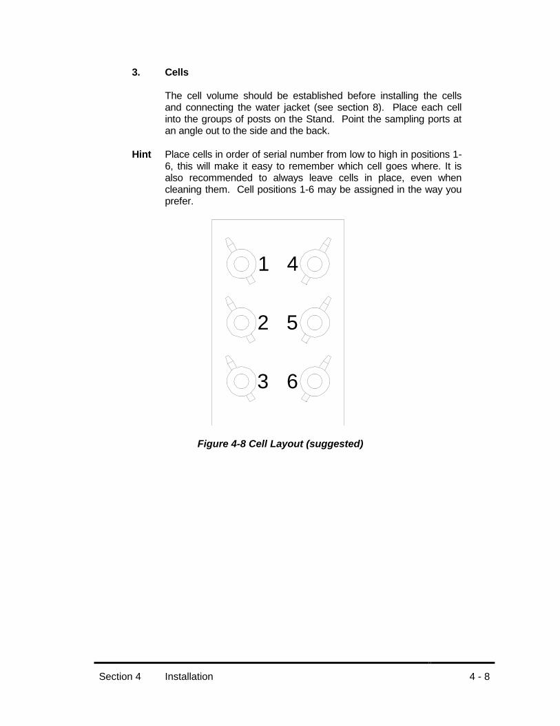
3. Cells
The cell volume should be established before installing the cells and connecting the water jacket (see section 8). Place each cell into the groups of posts on the Stand. Point the sampling ports at an angle out to the side and the back.
Hint Place cells in order of serial number from low to high in positions 1-6, this will make it easy to remember which cell goes where. It is also recommended to always leave cells in place, even when cleaning them. Cell positions 1-6 may be assigned in the way you prefer.
Figure 4-8 Cell Layout (suggested)
1
2
3
4
5
6

Section 4 Installation
4 - 9
4.7 Bath Circulator Connections
Install the 2 fittings into the back of the Bath Circulator. Connect the ¼ x ½ tubing to these fittings and clamp. Connect the other end with the smaller tubing to the cells. Each cell will then connect from one to the next. Make sure to connect the output from the Bath Circulator to the first cell.
Note: connect the luer fittings by pushing together and giving them a slight twist. Example: connect from the output of the Bath Circulator to the bottom of cell
one. from the top of cell #1 to the bottom of cell #2 from the top of cell #2 to the bottom of cell #3, etc. from the top of cell #6 to the bottom of the jacketed beaker
4.8 Jacketed Beaker The jacketed beaker is to be connected to the return tubing line between the last cell and the bath circulator. There are quick disconnect fittings supplied to make this connection (the quick disconnect fittings will stop the flow when they are disconnected). Make sure that the liquid is entering the beaker from the bottom and then going out the top. You may wish to place a small vessel inside the jacked beaker to hold the replacement solution. Place the vessel inside the jacketed beaker and a small amount of water around it. Ensure that there is enough water around the small vessel to adequately transfer heat.
4.9 Flow Indicator Connect the flow indicator in between any 2 cells; it is recommended to connect between cells 3 and 6 at the front of the unit. The flow indicator gives you a visual indication that the bath water is flowing through the system.

Section 4 Installation
4 - 10
4.10 Startup Evaluation
CAUTION The voltage indicated on the MultiFill and the bath circulator must be the same as the power source. If the incorrect voltage is indicated, do not plug in the instrument, and contact Hanson.
1. Check that the Stirring Control is on by viewing the display.
2. Fill the Bath Circulator with water (follow instructions in the Bath
Circulator manual); make sure there are no open connections in the tubing, and turn the power on. The unit will self test and then you will hear the pump start. Allow the system to run, checking for leaks. If a leak is detected, turn the power off and repair the problem. Once the Bath Circulator is working and there are no leaks, turn the power off.
Ambient conditions and bath circulator settings may affect temperature. Check the minimum temperature operation of the bath circulator before you do any testing. Do this by setting the bath temperature to 20 and monitoring the bath circulator displayed temperature to not exceed the setting requirement.
Hint: set the bath temperature to 32.5C to achieve a cell temperature of approximately 32C.
The pump speed setting should be set to HIGH.
3. To remove all the air in jacket part of the cells, turn the power on to
the Bath Circulator and tip each cell in order, starting with #1.
Note: if any of these steps did not work as described, return to the beginning of the installation section and check all connections, then refer to the troubleshooting section.

Section 5 Operating Instructions, Programming
5 - 1
Section Five- Operating Instructions
5.1 Speed Control Read the operation manual for the speed control before setting up, programming or operating this unit. It is recommended to set the speed to 400 and the interval to OFF. Set the power to 50%. If the power setting is turned up over 50%, the drive may heat up and cause the cells to operate above the desired temperature.
5.2 Bath Circulator Read the operation manual for the bath circulator before setting up, programming or operating this unit. It is recommended to set the temperature to 32.5C. Set the pump speed to 10%. If the pump speed is set too high it may heat the water over the desired temperature.

Section 6 Operation Instructions
6 - 1
Section Six – Operation and Setting Up
6.1 Overview
One of the most important factors to ensure a successful test is to deaerate the replace solution prior to the test. The following instructions are suggested; modifications to meet individual requirements are acceptable.
Always use the same magnet and helix with the same cell. Cell volume should be validated with the magnet and helix in place.
6.2 Cell Preparation
Bubbles under the membrane are an area of concern with vertical cells. Proper deaeration of the media, proper placement of the dosage wafer, and a correct sampling procedure will ensure bubble-free testing.
See figures in section 4 for parts identification. With cells in cell holders and water jackets tubes connected:
1. Prepare membranes; see membrane preparation in this section.
2. Ensure magnet and helix are in place in each cell.
3. With the female fitting and check valve connected to the bottom of
the cells, and the output sampling tube rotated upwards, pre-fill each cell with media until the cell is 90% filled. The bubble trap should have no bubbles, or just a small bubble in it. Use a new check valve for each test and check to ensure there are no leaks in this area while the cell is coming up to temperature.
4. Ensure there are no bubbles in the cell. If bubbles are noticed, run
the stirrer at 1000 rpm for a few seconds to release any bubbles. You may also insert a probe into the cell to help release bubbles.
5. Continue to fill each cell until there is a positive meniscus covering
the complete top of the cell. Allow a few minutes for the cell to warm to operating temperature.
6. Always ensure that the stirring is off before you place the wafer on
the cells. Place dosage wafer on cell, do this by holding the wafer with thumb and forefinger at about 30 degree angle to the top of the cell. Place the thumb and edge of wafer on one edge of the cell and then immediately roll the wafer onto the top of the cell. Inspect under the membrane for bubbles.
7. Place glass disk and then cell ring on cell; align side cut out of ring
for viewing into the cell if desired.

Section 6 Operation Instructions
6 - 2
8. With cell clamps adjusted, slide clamp onto cell, over the cell ring
and under the cell flange. Rotate the output tube to be pointing down and to the side.
9. Start the stirrers and the test by pressing the START/STOP key on
the stirring control; this is time zero.
Figure 6-1 Cell Preparation
Section 6 Operation Instructions
6 - 3
6.3 Membrane Preparation Parts Needed
1. Diffusion cell assembly, including, glass diffusion cell, donor wafer, glass disk, cell ring and clamp
2. Membranes (e.g. Gelman polysulfone HT450 0.45u #66221) 3. Application squeegee and tweezers. (The "squeegee" is a spatula-
like applicator used to smooth evenly the dosage form inside the drug dosage wafer)
4. Ethomeen 0-12 solution* and spot plate *Ethomeen solution is 15% Ethomeen 0-12 + 85% isopropyl
myristate (IPM). Ethomeen 0-12 [bis(2-hydroxyethyl)oleylamine] 5. Drug dosage form 6. Absorbent paper towels and "Kimwipe"-type tissues
Technique
1. Saturate membranes with Ethomeen solution on spot plate for 30 minutes.
2. Prepare receptor chamber of diffusion cells with slight overflow of media.
3. Prepare each membrane with drug dosage one at a time, as follows: a. Carefully lift membrane at its very edge with tweezers; place
on tissue and blot any extreme excess solution with tissue (a slight excess solution is desirable). Invert membrane on tissue and blot other side.
b. Carefully place membrane in center position on drug dosage wafer.
c. Set wafer, with membrane centered underneath, on paper towel, and press down on wafer.
d. Apply dollop of drug dosage form on top of membrane inside dosage wafer cavity.
e. Use squeegee to carefully smooth drug form over membrane, filling entire cavity of dosage wafer.
f. Use squeegee to wipe excess dosage off wafer. g. Repeat for each wafer.
4. Carefully lift loaded dosage wafer with membrane and place on top of receptor cell with membrane side towards cell media. Always place wafers onto cells in their numerical order. When placing on top of receptor, first put down one side of wafer, and then "roll on" the wafer (do not slide on), making sure no bubbles are trapped between receptor media and membrane, and hold in place with fingers.
5. Place glass disk and cell ring on top of donor cell assembly. 6. While pressing down with forefinger, slide clamp onto cell to lock
down top donor and bottom receptor halves of diffusion cell.

Section 6 Operation Instructions
6 - 4
6.4 Deaeration Technique
At the beginning of each day of analysis, it is necessary to deaerate the media. Prepare fresh media each day. This is conveniently done using a Millipore or equivalent two-piece filter holder, the bottom half being equipped with a medium or fine porosity sintered glass filter. The top piece should have a volume of 250 ml. 1. Place a 47 mm .045 porosity membrane over the sintered glass.
This membrane must be unaffected by 95% alcohol or IPM. A Gelman polysulfone or equivalent is recommended. Fit the lower half with a rubber stopper. The two pieces are then clamped together and fitted in a 500 ml vacuum flask containing a magnetic stirring bar approximately one inch length and ¼ inch in diameter.
2. Place the flask and filter holder on a magnetic stirrer and moderately spin the bar.
3. Operating the vacuum from the air pump (supplied with the start-up tool kit), pour the prepared media into the filter cup (top piece). After all of the media has passed through the holder, turn the stirrer off. Longer term action of the bar and vacuum could change composition of the media if it is comprised of water-alcohol. The media is now deaerated and ready for immediate use.
Section 6 Operation Instructions
6 - 5
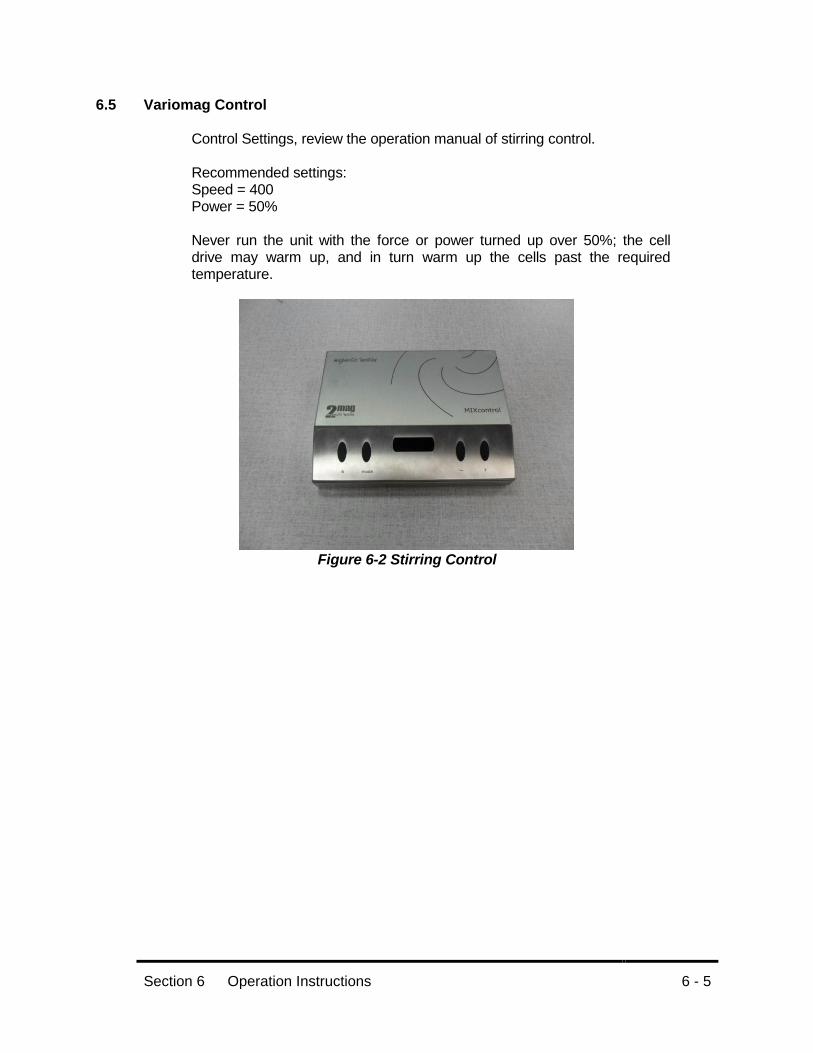
6.5 Variomag Control
Control Settings, review the operation manual of stirring control. Recommended settings: Speed = 400 Power = 50% Never run the unit with the force or power turned up over 50%; the cell drive may warm up, and in turn warm up the cells past the required temperature.
Figure 6-2 Stirring Control
Section 6 Operation Instructions
6 - 6
6.6 Bath Circulator Control Settings: review the operation manual of the bath circulator. It is suggested to set the pump speed to 10% (this is done through the keypad of the bath circulator). The displayed temperature range reading of the bath temperature may also be set; it is recommended to set the reading to one place (XX.X). The information for making these settings is located in the bath circulator manual. Ambient conditions and bath circulator settings may affect temperature. Check the minimum temperature operation of the bath circulator before you do any testing. Do this by setting the bath temperature to 20 and monitoring the bath circulator displayed temperature to not exceed the setting requirement. The bath circulator will need to be set above the goal temperature of the cells. The temperature difference between the setting and the actual temperature is dependent on ambient conditions. This difference should be tested.

Section 6 Operation Instructions
6 - 7
6.7 Starting and Running a Test
At this time it is considered that the manual has been read, the unit set up and tested for proper programming and operation.
1. Verify that the cell drives are ready to go, that all required
specifications are within tolerance and all hardware settings are ready.
2. Verify that the bath circulator is set to the desired temperature and
is controlling at that temperature.
3. Prepare the membranes. Note: it is a good idea to prepare an extra membrane.
4. Verify media source is deaerated and to temperature.
5. Verify the cells are filled and are at the required temperature.
6. Apply the wafers, cell tops and clamps to the cells.
7. Press the START/STOP key on the speed control, this is time “0”.
8. At the sample time point, press the START/STOP key on the
stirring control to stop the stirring.
9. Starting with cell 1:
a. Fill the syringe with media. Remember to pull the plunger all the way out until it stops.
b. Fill the cavity of the check valve using a pipette (this will keep a bubble from forming when the syringe is installed).
c. Insert the male luer of the syringe into the check valve and give a slight twist clockwise.
d. Place a vial on or a towel under the output tube from the cell.
e. Aspirate about 0.5 mL into the cell with a smooth and steady motion (this should be done slowly, taking about 10 seconds).
f. Place vial on the output tube from the cell and aspirate the remaining volume.
g. Remove the syringe by giving a slight pull while turning clockwise (always install and remove syringe while turning clockwise).
h. Repeat for each cell. i. After the last cell is complete, press START/STOP on the
stirring control to start the stirrers.
Note that the duration of sampling time is considered part of the overall test time.

Section 6 Operation Instructions
6 - 8
6.8 Cleanup
Proper cleanup of the system is very important. Sample material should not be left in the system for long periods of time (more than 4 days). It is recommended to clean up the system as soon after the test as possible. It is also recommended to leave all cells and tubing connected at all times. This will reduce the chances of breaking cells or inter-mixing cell components.
Cell Top:
1. At the end of the test, dismantle the cell tops from the diffusion
cells. Remove the clamps, tops and membranes. 2. Clean the Teflon washers and their glass tops by removing the
ointment or cream with a tissue and wash them in warm water. 3. Finally, rinse them with alcohol and allow to air dry.
Figure 6-3 Vacuum Pump and Flask
The Vacuum Pump and Flask are accessory items which are part of the “Start-Up Tool Kit”. Connect the system as shown and turn the power switch on. Use this device or one similar as follows. The following steps are recommended and may be changed to fit individual requirements.
Section 6 Operation Instructions
6 - 9
Cell and Helix: 1. Use the stainless probe tip and place into cell to drain; rinse this
cell with alcohol while continuing to drain, allowing the magnet and helix to turn.
2. Remove helix and rinse over cell with alcohol. Rinse and drain cell until satisfied it is clean.
3. Replace helix and fill cell to near top. 4. Repeat for each cell, ensuring magnet and helix have been
replaced into the original cell.
Plastic Vessel: Never allow the vessel to fill more than ¾ full. Lift the cover from the plastic vessel and remove material from inside.

Section 7 Troubleshooting
7 - 1
Section Seven - Troubleshooting
7.1 Contacting Hanson Research Corporation or your local representative for
Technical Support.
To expedite your request for technical support, please supply or have the following information available:
1. Model and serial numbers of the instrument(s). 2. System configuration. 3. How long the equipment had worked before the problem occurred and
how old the equipment is. 4. Any background information, recent repairs, or parts replaced to date. 5. How the system is being used, what the application is. 6. Detailed information about the problem (what is working and what is not). 7. Detailed troubleshooting steps that have been taken to date.
7.2 Liquid Flow
Problem Possible Causes Recommended Action
Sample volumes incorrect.
1. Not using vial caps. 2. Leaking syringe. 3. Leaking fittings or joints.
1. Use recommended vial caps 2. Check and replace syringe. 3. Check all fitting connections for
leaks and fix or replace any leaking fittings or joints.
Problem Possible Causes Recommended Action
Excessive carry-over.
1. Inadequate rinse volume.
1. Increase rinse volume to a minimum of 0.5mL.
Problem Possible Causes Recommended Action
Drug loss. 1. Sample adsorbing to fittings or other parts of the liquid flow path.
1. Evaluate fittings, sample may be absorbing to them. See section 3 for wetted parts.
Consult the operation manuals for the stirring control and the bath circulator for more information.
Section 8 Maintenance
8 - 1
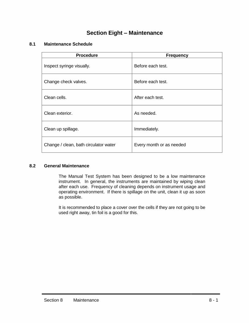
Section Eight – Maintenance
8.1 Maintenance Schedule
Procedure Frequency
Inspect syringe visually.
Before each test.
Change check valves.
Before each test.
Clean cells.
After each test.
Clean exterior.
As needed.
Clean up spillage.
Immediately.
Change / clean, bath circulator water
Every month or as needed
8.2 General Maintenance The Manual Test System has been designed to be a low maintenance instrument. In general, the instruments are maintained by wiping clean after each use. Frequency of cleaning depends on instrument usage and operating environment. If there is spillage on the unit, clean it up as soon as possible. It is recommended to place a cover over the cells if they are not going to be used right away, tin foil is a good for this.

Section 8 Maintenance
8 - 2
8.3 Cell Volume Evaluation Note; other methods may be used to determine cell volume. Cell volume evaluation should be repeated if the magnet or helix is replaced. 1. Place the Helix and magnet in a dry cell. Place a piece of
parafilm on the top of the cell. Assemble the cells as normal and clamp.
2. Plug the sample port of cell.
3. Weigh the cell (empty).
4. Remove the plug and while holding the cell upside down, fill the
cell through the sampling port (with room temperature water) until the cell is filled. Insure there are no bubbles in the cell. Do not fill the bubble trap.
5. Place plug on replace port of cell and then remove the filling
syringe.
6. Weigh the cell again (full) and calculate for density.
7. Repeat at least twice more to insure accuracy.
8.4 Syringe Volume Evaluation
Note; other methods may be used. 1. Fill syringe to capacity (pull plunger all the way out until it stops).
2. Weigh empty vessel.
3. Aspirate complete contents into vessel and weigh. Calculate for
density.
4. Repeat at least twice more to insure accuracy.
Syringe volume evaluation should be repeated at least every 6 months.
Section 9 Moving and Storage
9 - 1
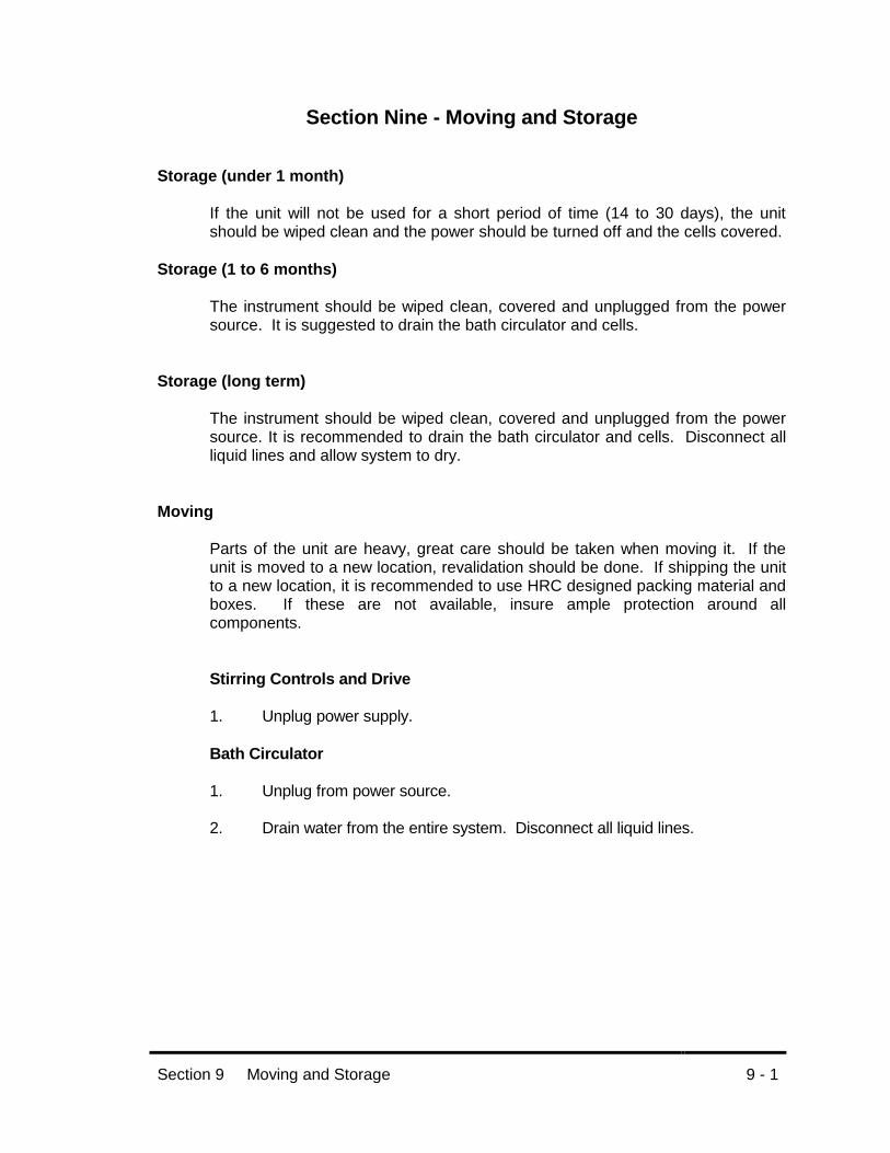
Section Nine - Moving and Storage Storage (under 1 month)
If the unit will not be used for a short period of time (14 to 30 days), the unit should be wiped clean and the power should be turned off and the cells covered.
Storage (1 to 6 months) The instrument should be wiped clean, covered and unplugged from the power source. It is suggested to drain the bath circulator and cells.
Storage (long term)
The instrument should be wiped clean, covered and unplugged from the power source. It is recommended to drain the bath circulator and cells. Disconnect all liquid lines and allow system to dry.
Moving
Parts of the unit are heavy, great care should be taken when moving it. If the unit is moved to a new location, revalidation should be done. If shipping the unit to a new location, it is recommended to use HRC designed packing material and boxes. If these are not available, insure ample protection around all components.
Stirring Controls and Drive
1. Unplug power supply. Bath Circulator
1. Unplug from power source.
2. Drain water from the entire system. Disconnect all liquid lines.
Section 10 Parts, Supplies and Accessories
10 - 1
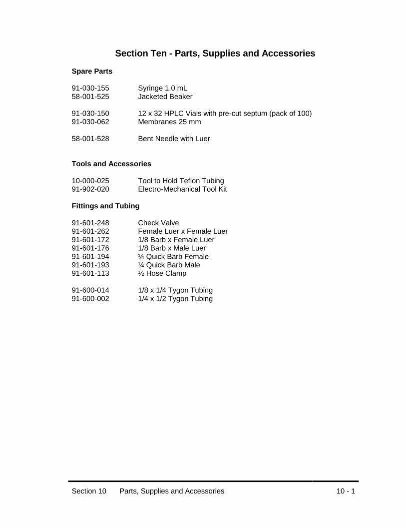
Section Ten - Parts, Supplies and Accessories
Spare Parts
91-030-155 Syringe 1.0 mL 58-001-525 Jacketed Beaker 91-030-150 12 x 32 HPLC Vials with pre-cut septum (pack of 100) 91-030-062 Membranes 25 mm 58-001-528 Bent Needle with Luer Tools and Accessories 10-000-025 Tool to Hold Teflon Tubing 91-902-020 Electro-Mechanical Tool Kit Fittings and Tubing
91-601-248 Check Valve 91-601-262 Female Luer x Female Luer 91-601-172 1/8 Barb x Female Luer 91-601-176 1/8 Barb x Male Luer 91-601-194 ¼ Quick Barb Female 91-601-193 ¼ Quick Barb Male 91-601-113 ½ Hose Clamp 91-600-014 1/8 x 1/4 Tygon Tubing 91-600-002 1/4 x 1/2 Tygon Tubing

Section 10 Parts, Supplies and Accessories
10 - 2
Cells, Tops and Clamps
58-001-453/454 Cell 9 mm X 4 mL Clear/Amber 58-001-457/458 Cell 15 mm X 7 mL Clear/Amber 58-001-461/462 Cell 15 mm X 12 mL Clear/Amber 58-001-467 Helix Kit 9 mm (for 4 and 7 mL cells) 58-001-468 Helix Kit 15 mm (for 12 mL cells) 58-001-450 Cell Clamp Assembly 58-001-507 Cell Ring 58-001-506 Glass Disk 58-001-518 Dosage Wafer 9 mm 58-001-521 Dosage Wafer 15 mm

Section 11 Sales and Service Offices
11 - 1
Section Eleven - Sales and Service Offices The Manual Test System is sold and serviced by a worldwide network of dealers and distributors. If you need additional accessories, replacement parts, or require service information, you can either contact your local agent, or you can contact Hanson Research Corporation at their worldwide headquarters:
Hanson Research Corporation 9810 Variel Avenue Chatsworth, CA 91311 USA Phone: (818) 882-7266 Toll free in USA and Puerto Rico: (800) 821-8165 FAX: (818) 882-9470
Internet: www.hansonresearch.com

Section 12 Warranty
12-1
Section Twelve - Warranty GENERAL WARRNTY: Hanson Research Corporation products are warranted for one full year including parts and labor. An extended three-year warranty is available to USA domestic customers at time of purchase. International dealer warranties may vary. Optional service contracts may be available after warranty period expires. Hanson Research Corporation makes no warranty, expressed or implied, for glassware, consumables, or products not manufactured by Hanson Research Corporation, as evidenced by nameplate on the item or other designation. We will give responsible assistance to buyer in obtaining from the respective manufacturer whatever adjustments are reasonable in light of manufacturer’s own warranty. Hanson Research Corporation shall be released form any and all obligations under any warranty, either expressed or implied, if the product covered is repaired or modified by other than its own personnel, or made without written authorization of Hanson Research Corporation. There are no other warranties, expressed or implied, and Hanson Research Corporation shall not be liable under any circumstances for consequential damages.