manual - global sourcesp.globalsources.com/images/pdt/spec/017/k1045202017.pdf · sh-2002ah manual...
TRANSCRIPT

SH-2002AH Manual 1
Beijing Flourishing Start Digital Technology Co., Ltd
CNC Cutting Controller
(SH-2002AH)
Manual Address: Room604, Zeyang Mansion, No.166 Fushi Road, Shijingshan District, Beijing, China, 100043 Tel: +86-10-88909235 Fax: +86-10-88909277 Email: [email protected] Mobile: +86-15901069532
Beijing Flourishing Start Digital Technology Co., Ltd

SH-2002AH Manual 2
Beijing Flourishing Start Digital Technology Co., Ltd
* Please read carefully this manual before use the system.
Attention: 1. After open the packing case, please check the goods and whether accord with the list.
2. This manual only for Little Flame/Plasma cutting machine produced by Beijing Start Microstep.
3. Operating environment temperature is 0-40℃,Relative humidity should be controlled in 0-85%.
Under high-temperature, high-humidity, caustic gas, must adopt special defend measure. 4. In order to ensure control system working normally and improve system reliability and ensure the
operator’s safety, Cutting machine tools and control system all should be well earthed.
5. Control system should be insulated from outside to avoid dirt and powder entering and result in
control system working abnormally, system parts damaged, etc.
6. The system operator should be strictly trained and specified special operator.
7. The inside power source of CNC system don’t allowed to connect other electric apparatus.
8. Toward some area that power supply is nonstandard (such as zero line and earth wire sharing or
no zero line), in order to ensure control system working normally and improve system reliability and sure operator’s safety, you must use isolation transformer that three-phase/two-phase AC380V transfer to two- phase AC220v between electric network and control system.
9. If have problem, please contact our company. If don’t familiar with system, are not allowed to
take down system.

SH-2002AH Manual 3
Beijing Flourishing Start Digital Technology Co., Ltd
Contents
SECTION 1 Overview-----------------------------------------------------------------------------------------6 1.1Function---------------------------------------------------------------------------------------------6 1.2Features----------------------------------------------------------------------------------------------6 1.3Hardware Specifications- -----------------------------------------------------------------------------6
SECTION 2 Main Menu---------------------------------------------------------------------------------------7 SECTION 3 Auto Function------------------------------------------------------------------------------------8
3.1Auto menu instruction-----------------------------------------------------------------------------8 3.2Function----------------------------------------------------------------------------------------------9 3.3START Auto cutting------------------------------------------------------------------------------10 3.4Control and Compensate during Auto cutting-------------------------------------------------10 3.5Cutting back along origin trace-----------------------------------------------------------------10 3.6Break resume and power down come back----------------------------------------------------11 3.7Select Segment function--------------------------------------------------------------------------11 3.8Extend pierce--------------------------------------------------------------------------------------12
SECTION 4 Edit-----------------------------------------------------------------------------------------------13
SECTION 5 Instructions-------------------------------------------------------------------------------------14
5.1Programming symbol-----------------------------------------------------------------------------14 5.2Coordinate system--------------------------------------------------------------------------------14 5.3G Basic prepare instruction----------------------------------------------------------------------15 5.4M Function-----------------------------------------------------------------------------------------18
SECTION 6 Parameter Setup------------------------------------------------------------------------------20
6.1Speed parameters---------------------------------------------------------------------------------20 6.2System parameters--------------------------------------------------------------------------------21 6.3Flame parameters---------------------------------------------------------------------------------21 6.4Plasma parameters--------------------------------------------------------------------------------22 6.5Control parameters--------------------------------------------------------------------------------23
SECTION 7 Diagnoses----------------------------------------------------------------------------------------24
SECTION 8 Library Shapes---------------------------------------------------------------------------------25
8.1Part option------------------------------------------------------------------------------------------25 8.2Set and nest part-----------------------------------------------------------------------------------25
SECTION 9 Outer Connect----------------------------------------------------------------------------------27
9.1Input signal-----------------------------------------------------------------------------------------27 9.2Outside output-------------------------------------------------------------------------------------27 9.3Definition----------------------------------------------------------------------------------------- -28 9.4Outside Driver Interface------- ------------------------------------------------------------------28

SH-2002AH Manual 4
Beijing Flourishing Start Digital Technology Co., Ltd
9.5Back panel definition-----------------------------------------------------------------------------29
APPENDIX 1 Update Software instruction---------------------------------------------------- 30
APPENDIX 2 Install Dimension-------------------------------------------------------------------31

SH-2002AH Manual 5
Beijing Flourishing Start Digital Technology Co., Ltd
Section 1 Overview 1.1 Function
SH-2002AH/ST Flame/Plasma cutting machine system, control machine tool cutting use Flame or plasma. The operating
display by system adopt window hint step by step. Under main menu, after press one function key, system will display the sub-menu..
According to the hint and press 【F1】 to 【F6】 to select. Press ESC to quit and return to back menu. 1.2 Features
◆ High-reliability, Prevention of strong plasma disturb and lightning strike etc;
◆ The storage of user program can reach to 16-32M, the cutting program can have 10000 lines;
◆ Chinese and English can switch easily, can execute, display and save Chinese files name;
◆ Rich software function, Applied cutting technique, special is the deal with of little line, it can be used widely in Ad, Iron
technique etc;
◆ Can extend to 4 axes interconnected function;
◆ Dynamic shape attach 5.7 LCD display, it is perfect;
◆ Adopt U disk to Read/Write program and Upgrade Software. 1.3 Hardware Specifications
1.Industrial gradeARM7 chip;
2.System offer 4 relay:
1)Gas and pre-Oxy or Automatic Height Control System;
2)Cut Oxy or Plasma Arc On;
3)Torch up;
4)Torch down;
3.System offer: Input 7 ports, output 4 ports;
4.Interconnected: Two axes, can extent to Four axes;
5.Pulse Equivalent: Electronic gear, numerator and denominator can reach to 1-65535.
6.Max speed: When the Pulse Equivalent is 1μ, speed is 6m/minute;
7.User’s program space:16-32M;
8.Size:300*200*85(mm);
9. Work Temperature: 0℃ – 40℃.

SH-2002AH Manual 6
Beijing Flourishing Start Digital Technology Co., Ltd
Section 2 Main menu
【F1】AUTO: Automatic mode;
Fig 2.1 Main menu
【F2】EDIT: New files, Save files, Delete files etc;
【F3】PARA: Setup Parameters;
【F4】DIAG: Diagnose I/O Ports;
【F5】LIB: Shape Library
【F6】SETB: Comeback function after power cut.
【INS】:it is used for increasing LCD brightness.
【DEL】:it is used for decreasing LCD brightness.
【G】【G】【3】:Initialize, show as follow:
FILE FORMAT PARAMETER 中文方式
Fig 2.2 Initialize dialog box
FILE FORMAT ―――Format user’s program area;
PARAMETER ―――Come back parameters setup;
中文方式 ―――Chinese/English select.
SH-2002AH Manual 7
Beijing Flourishing Start Digital Technology Co., Ltd
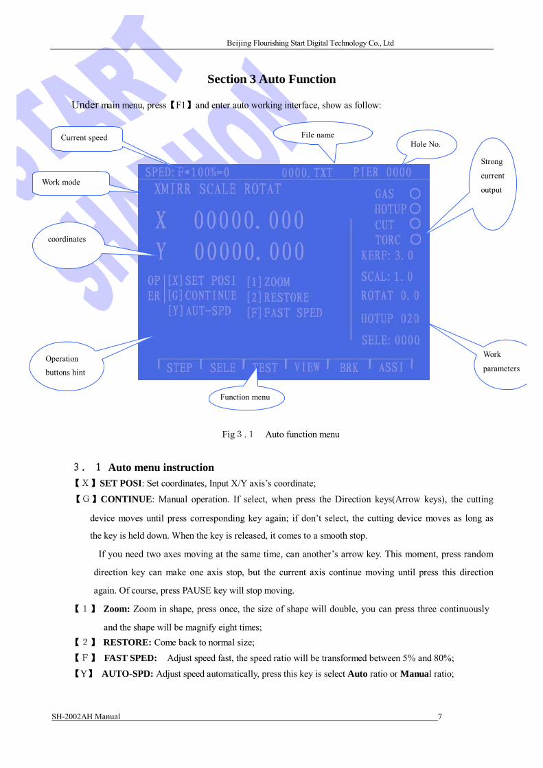
Section 3 Auto Function
Under main menu, press【F1】and enter auto working interface, show as follow:
Current speed File name Hole No.
Work mode
Strong
current
output
coordinates
Operation
buttons hint
Work
parameters
Function menu
Fig3.1 Auto function menu
3.1 Auto menu instruction
【X】SET POSI: Set coordinates, Input X/Y axis’s coordinate;
【G】CONTINUE: Manual operation. If select, when press the Direction keys(Arrow keys), the cutting
device moves until press corresponding key again; if don’t select, the cutting device moves as long as
the key is held down. When the key is released, it comes to a smooth stop.
If you need two axes moving at the same time, can another’s arrow key. This moment, press random
direction key can make one axis stop, but the current axis continue moving until press this direction
again. Of course, press PAUSE key will stop moving.
【1】 Zoom: Zoom in shape, press once, the size of shape will double, you can press three continuously
and the shape will be magnify eight times;
【2】 RESTORE: Come back to normal size;
【F】 FAST SPED: Adjust speed fast, the speed ratio will be transformed between 5% and 80%;
【Y】 AUTO-SPD: Adjust speed automatically, press this key is select Auto ratio or Manual ratio;

SH-2002AH Manual 8
Beijing Flourishing Start Digital Technology Co., Ltd
【F+】【F-】 ADD/SUB speed: Adjust the value of speed ratio;
【F+】【F-】 ADD/SUB speed: Adjust the value of speed ratio;
【IGNTING】Strong current control key, refer to M20
【PRCTRL】Strong current control key, open Preheat Oxy electromagnetic valve, refer to M24
【GAS】Strong current control key, open Acetylene(GAS) electromagnetic valve, refer to M10
【CUTOXY】Strong current control key, open CUTOXY electromagnetic valve, refer to M12
【PREHEA】Strong current control key, complete a pierce course, operation as below:
Flame cutting — First torch up (M72), open CUTOXY(M12), Torch down(M73);
Plasma cutting— Execute M07.
[SKILL] This is a very important function, and it will be used in PAUSE, BACK, EXTEND
HOLE again and again, press PREHE (pierce)key, make this work finished perfectly.
【CLOSE】Strong current control key, Close all strong current outputs;
【S↑】Strong current control key, press: Torch up Release: Raise stop;
【S↓】Strong current control key, press: Torch down Release: fall stop;
【↑】【↓】【←】【→】Direction key.
3.2 Function
【F1】STEP: Rip cut, select this function(highlight), system will hint:
Distance: 0.0 (Default: the value last input)
Under this mode, press Direction key (ARROW key) once, The torch will move a set value.
【F2】SELE: Specify system start cutting from random segment(or pierce). Usually be used from the
program’s some segment start to cut, or only cut part. for more detail, Refer 3.7; 【F3】TEST: (Dry run) When system working, moving normally, but don’t execute outside strong current
operations;
【F4】VIEW: It can check the program whether right or not. Select this function, display the shape that
expected cutting, there are “+” cursor in center, press 【1】or【2】key to zoom or comeback the shape
size. Press Direction key can move the display position;
【F5】BRK: (Come back Break), Select this function, press 【START】key, it will execute Come back Break
function, for more detail, refer to 3.6;
【F6】ASSI: Enter next menu, show as follow:
Fig 3.2 Assistant menu ① 【F1】KERF: Set the kerf value, press this key, it will hint input kerf compensate width. if not, input 0;
② 【F2】RTRN: Press the key, the machine tool will return to Reference Point rapidly(Specified by G92);
③ 【F3】SCALE: Zoom scale, system will hint input value, and display the scale mark, when cutting, it will
zoom in or zoom out according to this scale value, this function is useful when cut arts character;

SH-2002AH Manual 9
Beijing Flourishing Start Digital Technology Co., Ltd
④ 【F4】ROTAT: ROTATE, Because the steel board that expected cutting can not be placed perfectly
once, it needs rotate by a certain angle to cut. Press【F4】key and enter next menu:
Fig 3.3 Rotate
Press【F1】hint input angle value, after confirmed, system will rotate the set angle then cutting. Attention:
counter-clockwise is positive. It is also can Measure a line’s start point and end point to let system identify
automatically ,then computer the revolve angle, means as below:
First confirm BASE LINE, Usually use a edge of the steel board as BASE LINE; After move torch to
BASE LINE, Press【F2】to set START POINT. Let the torch move to END POINT along BASE LINE( The
further of the distance between START POINT and END POINT, the more precision it will be), The torch aim
to BASE LINE, press【F3】to set END POINT. The angle will be computed by system, after completed revolve
function, the angle will be displayed.
⑤ 【F5】MIRR: Press【F5】,you can select X MIRR, Y MIRR, press again no mirror. If select X MIRR,
Allow the X dimensions to be negated. The result will be a mirror image of the current part in memory.
If select Y MIRR, Allow the Y dimensions to be negated. The result will be a mirror image of the
current part in memory; No mirror is in default.
⑥ 【F6】MDI:(Manual Data Input) No this function at present.
3.3 START Auto cutting Before Auto cutting, Make sure the program is correct, select appropriate speed, After all prepared, there are
two means to start cutting.
1.Press “START” (Green button) key;
2.Press the “Start” button that outside connect.(Refer 8.3).
3.4 Control and compensate during Auto cutting
Auto cutting start, Only these keys can be enable:
1. “PAUSE”:Red button, press this key, system will close CUTOXY(When plasma, close ARC SWITCH),
close Automatic Height Control System(M39), and hold the current display. If press “START” key, system
will continue cutting. During PAUSE state, if find the cutting dimension have error and want to change the
cutting position, can directly press 【↑】【↓】【←】【→】to adjust the torch’s position (This moment the
ratio is 5%) and the system consider the move is compensate. After adjust, press “START” system will ignore
the moving distance for compensate and continue cutting according to the before position. If press “ESC”
system will come back main menu.
2. 【F↑】、【F↓】Adjust speed.
3.【Pgup/S↑】、【Pgdn/S↓】 Control Torch up/down.
4.【STOP】:it is outside connect key(Refer 6.1), connect input port. When it enable, stop all moving.
3.5 Cutting back along origin trace
During cutting, if there have cutting uncompleted and need back cut along origin trace, deal with as follow:

SH-2002AH Manual 10
Beijing Flourishing Start Digital Technology Co., Ltd
1.Press “PAUSE” key, system will display mark and hint F5 BACE F6 FORWARD.
Press【F5】system will back along origin trace, press【F6】,forward along origin trace base on back. If get
to the position, press “PAUSE” key and repeat the above state, select BACE or FORWARD again;
2.During back operation, if encounter G00( arrive a Pierce), system will pause, operator can select whether
back continue or forward;
3.After back to the specified position, can press corresponding strong-current key( like Preheat , CUTOXY
etc). Usually adopt means : after preheat well, press【PREHEA】key, If flame, Torch up ,Open
CUTOXY, Torch down and system continue cutting; if plasma, Open start arc switch, after start arc
finish, system continue cutting.
4.The above state operation can be executed repeatedly until get satisfied effect.
5.When pause, press【ESC】,system will quit cutting state.
6.The number of program that can back is 300 at most. If it is break point resume or select
segment cutting, the start line that back is the current break or the segment line.
3.6 Break resume and power down come back
1.Break resume——Pause by operator, system will save current position of torch tip as a break point, and the
break point will be saved permanently. Under AUTO mode, if the current program have no change, press
【F5】to select Break resume function, press 【START】again, system will start resume break point, when
find it, system will hint three select: 1) Return to origin trace——Return to break point position by G00’s speed;
2) Cutting return——When break resume , the torch should leave a little distance from break point, in
order to the break point more smooth;
3) Current position pierce——Start cutting at current position, continue operation that after pause.
This moment ,press corresponding strong current button(INGITING, CUTOXY etc)
Suggest: After preheat, then pres【s PREHEA】, system will continue cutting from break point position.
After find break point, press【ESC】,system will quit cutting state.
2.Attention: Whether Break point resume or Power cut resume, it is prohibit to change the cutting
program ,rotate angle or scale etc, or else system will not find the break point.
3.7 Select Segment function
Specify system start cutting from random segment (or pierce). Press【F2】,System will enter next menu:
Fig 3.4 Select Segment
【F1】L-SEL ―― Select cutting start point according to program Row No.
【F2】P-SEL ―― Select cutting start point according to PIERCE.
System will hint input the selected number, and set this cutting mark
Usually have two instances:
1) Cutting some part of the program over again;
2) Cutting the after program that from some segment over again.

SH-2002AH Manual 11
Beijing Flourishing Start Digital Technology Co., Ltd
For former, usually find a disuse material, aim at pierce point cutting directly(CURRENT POSI-); For later,
position from reference (FROM REFERENCE). System will hint:
CURRENT POSI-
FROM REFERENCE
Fig 3.5 Hint dialogue
If select “CURRENT POSI-” , when system cutting ,first draw full shape, and in the pierce position,
draw a large “+” cursor, the operator press【1】can zoom in shape, and view whether is the pierce position. If
don’t satisfied, press【ESC】to quit and select again. If it is the wanted pierce point, can by strong-current
switch , IGNITING, PRCTRL, Press 【PREHEA】key to start;
If select “FROM REFERENCE”, Before start, The torch should be aim at Reference point. After start,
system control torch move to hole, and waiting for piece. The other same to above state. 3.8 Extend Pierce
During Auto cutting, when cutting deep steel board, need use EXTEND PIERCE. Means: Before pierce,
move the torch to brink of steel board, start preheat, after preheat finished, press【PREHEA】, the torch cutting by
selected speed along straight to Hole point, then continue cutting.
Adopt EXTEND PIERCE, first should set parameter EXTEND PIERCE is 1(enable), when need pierce,
system will hint as below:
HOLE
MOVE HOLE NO HOLE
Fig 3.6 Extend Pierce dialogue
1 HOLE--- Current position pierce, Original position pierce, usually be used on inside hole;
2 MOVE HOLE --- Extend pierce, Operator press【↑】【↓】【←】【→】to adjust the torch’s position to
extend brim of steel board(this moment the speed ratio is 5% automatically) start preheat, after preheat finished,
press【PREHEA】, the torch cutting by selected speed along straight to Hole point, then continue cutting.
3 NO HOLE --- System will move from current position.

SH-2002AH Manual 12
Beijing Flourishing Start Digital Technology Co., Ltd
SECTION 4 Edit
Under main menu, press【F2】key to enter edit interface: 1)【F1】New program, clear editing area.
Fig 4.1 Edit
2)【F2】Load program, select program to load to user’s program area. System will list all files’ name, move
cursor to select. Press ENTER and add this program to edit area. If press ESC, quit.
3)【F3】Save program, When program edit finish, press this key ,system hint:
0000.TXT
System display the current program’s name, can be amended. If press ENTER, the program will be saved to
program area by amended name, if press ESC, quit. NOTE: The total characters including file name
and extension can’t over 12.
4)【F4】Delete file.
5)【F5】Delete a line.
6)【F6】Transfer file, this system sustain U disk, press【F6】, enter next menu:
Fig 4.2 U Disk operation
Press【F1】U disk’s file transfer to system memory; Press
【F2】System program area’s file transfer to U disk.

SH-2002AH Manual 13
Beijing Flourishing Start Digital Technology Co., Ltd
5.1 Programming symbol
SECTION 5 Instructions
Every action of CNC machine running according to regulate program, every machine program be composed
of some instruction segment, and every instruction segment be composed of some Function word, each function word must start by letter, parameter follow.
Definition of function word:
N The No of instruction segment
G Prepare function
M Assistant function
S Main axis function
L Cycle times or delay time
X X axis absolute coordinate value
Y Y axis absolute coordinate value
U The increment that X axis relative to current position
V The increment that Y axis relative to current position
I When cutting arc, the value that the coordinate of the circle centre subtract X axis start value
J When cutting arc, the value that the coordinate of the circle centre subtract X axis start value
R Specified arc radius
F Specified moving speed, used for G01,G02 and G03
Note 1: There are some appointments:
X[U]n -- It can be X or U, n express a value, but only appear once.
Y[V]n -- It can be Y or V, n express a value, but only appear once also.
PPn -- It can be assembled random axis, at least include one axis ,also can include two axis.
Note 2: The instruction execute order is sequence (except transfer and call sub program instruction); In same
program the M,S and T will be executed before G instruction.
5.2 Coordinate system Adopt standard coordinate system, that is Descartes coordinate system, Show as follow:
+Y
+X
5.3 G Basic prepare instruction
1) G92 Reference point setup When setup program cutting, the cutting start point (reference point) must be put program’s begin and setup by

SH-2002AH Manual 14
Beijing Flourishing Start Digital Technology Co., Ltd
absolute coordinate.
Format: G92 Xn Yn
If it has no content after G92, the current coordinate of X and Y is reference point. Usually when use
machine tool to orientation, After G92, don’t allow follow X and Z .
2)G90/G91
Absolute coordinate system G90(in default)/ Relative coordinate system G91;
When use G90, The value of X and Y is absolute coordinate, U, V is relative value; When use G91, X,Y and
U ,V all are relative value.
Format G90
Format G91
Example 1: G92 X0 Y0
G91 // Relative coordinate
G00 X100 Y100 // Positioned poin(t 100,100)by fast speed, Same to G00 U100 V100
G01 X500 Y100 // Cutting to(600,200)by line, Same to G01 U500 V100
Example 2: G92 X0 Y0
G90 // Absolute coordinate( in default) G00 X100 Y100 // Positioned point(100,100)by fast speed G01 X600 Y200 // Cutting to (600,200)by line
3) G20/G21 Inch / Centimeter
G20 Inch
G21 Centimeter (In default).
Format G20
Foramt G21
4) G00 Dot Move
Use this instruction can quickly move to specified position, When two axes all have displacement, system will
move from start point to end point by The most limit speed multiply ratio. When G00 move, it will be effect by
speed ratio.
Format: G00 X[U]n Y[W]n
or G00 PPn
Example:
G92 X0 Y0
G00 X120 Y280
(or G00 U120 V280)
M02
+Y +280
Current Torch position
Torch target position
+X
+120

SH-2002AH Manual 15
Beijing Flourishing Start Digital Technology Co., Ltd
5) G01 Straight line cut
Use this instruction, can straight move to the specified position. As cutting move instruction, it can
interpolation move single or two axes. The speed can appointed by F command.
Format: G01 X[U]n Z[W]n [Fn]
Or G01 PPn [Fn]
Example:G92 X0 Y0
G00 X200 Y95
G01 X80 Y235
(or G01 U-120 V145)
M02
+Y
+235 +95
Current Torch position
Torch target position
+X
+80 +200
6) G02/G03 Arc cut
This instruction be used for arc interpolation, it have sequence arc G02(anticlockwise) and contrary arc
G03(clockwise). The set of direction please refer picture below:
Format G02[03] X[U]n Y[V]n In Jn [Fn] or:G02[03] X[U]n Y[V]n Rn [Fn]
G02[03]PPn In Kn [Fn] or: G02[03] PPn Rn [Fn]
+Y
G02
70 O’
50 G03
Example (G02):
G92 X0 Y0
G00 X40 Y50
G02 X160 V0 I60 J20
G28
M02
Example(G03):
O +40 +100
+160 +X G92 X0 Y0
G00 X40 Y50
G03 X160 V0 I60 J20 Current Torch position
Torch target position
(or G03 X160 V0 R63.25)
G28
M02
Explain:
l I and J is increment that X and Y axis direction centre of circle relative to start point(centre of circle
subtract start point).
l R is radius ( R is positive value, when arc≤180°,you can use R to express radius). If specified I and J, don't use R; If specified R, don't use I and J.

SH-2002AH Manual 16
Beijing Flourishing Start Digital Technology Co., Ltd
7) G04 Pause/Delay instruction
This instruction be used for set time delay, when the program execute this ,it will delay time that L set. Unit:
second
Format G04 Ln
Example: G04 L2.4 (delay 2.4s)
During execute G04,press【START】will stop delay and go on executing the program after G04.
8) G26,G27,G28 Return Reference point
This instruction can make the cutter return to reference point automatically.
Format: G26 X axis return to reference point
G27 Y axis return to reference point
G28 X and Y axis return to reference point at the same time
Example:G28 (X and Y return to reference point at the same time, same to G00)
9) G22/G80 Loop sentence
G22 is the start of cycle, and specify the cycle times L. G80 is end sign of cycle. This instruction can use nest,
but can’t over 5.G22 and G80 that nearest follow compose a cycle body.
Format: G22 Ln_ (L specified cycle times) Cycle body
G80
(end symbol or NEXT)
Example: N000 G92 X100 Y100
N001 G00 X60 Y80
N002 G22 L5 - First layer start
N003 G00 V50 U-25
N004 G22 L5 - Second layer start
N005 G01 U5 V-10
N006 G80 - Second layer end
N007 G80 - First layer end
N008 G28
N009 M02
5.4 M Function M00 Program pause. After execute, program pause, press 【START】,continue.
M02 Program end. After execute, program will in waiting state.

SH-2002AH Manual 17
Beijing Flourishing Start Digital Technology Co., Ltd
M30 Same to M02
M10/M11 GAS (acetylene) valve open. M10(open), M11(close)
M12/M13 CUTOXY valve open. M12(open), M13( close)
M14/M15 Torch Up switch, M14(open), M15(close)
M16/M17 Torch Down switch, M16(open), M17(close)
M24/M25 Standby. M24(open), M25(close)
M20/M21 IGNITING switch, M20(open), M21(close)
M07 Pierce loop.
M08 Close cutting loop.
M07 Pierce loop
Flame cutting operation sequence: 1.If GAS(Acetylene) valve don’t open, open GAS igniting;
2. Torch down,(TORCHDN TIME, refer to M71);
3. Open PRCTL valve to preheat delay, if the preheat time isn’t enough, press【PAUSE】,The preheat time
will be extended, if preheat finished, press【START】, the delay time will be saved to HOTUP TIME
parameter automatically;
4. Torch up (PIERCEUP TIME refer M72);
5. Open CUTOXY valve (M12), After delay “PIERCE TIME” , Torch down(PIERCEDN TIME M73);
6. Open Automatic Height Control System (M38), start to run next program.
Plasma cutting operation sequence: 1. Torch down( TORCHDN TIME, refer to M71);
2. If TORCH LOCATE TIME (parameter setup) is available, torch down until encounter down-limit
switch, fall stop; Torch up, after delay “TORCH LOCATE TIME” , torch stop;
3.Open start arc switch;
4.Check “ARC VOLTAGE OK” signal, if the parameter ARC VOLTAGE CHECK is 0, it don’t check ARC
VOLTAGE, delay 0.5S;
5.Open Automatic Height Control System (M38), start to run next program.
M08 Close cutting loop
Flame cutting operation sequence: 1.Close CUTOXY(M13);
2.Close Automatic Height Control System (M39);
3.Torch up(M70);
Plasma cutting operation sequence: 1.Close START ARC switch;
2.Close Automatic Height Control System (M39);
3.Torch up(M70);
M50 Pierce action:
1. Torch up(M72), When plasma, no this action;
2. Open CUTOXY(M12), open plasma Start Arc, check “Arc Voltage success” signal;

SH-2002AH Manual 18
Beijing Flourishing Start Digital Technology Co., Ltd
3. Torch down(M73), When plasma, no this action;
4. Open Automatic Height Control System(M38).
M52 IGNITING Loop: Operate sequence: Open GAS valve(M10), Open high-voltage
IGNITING(M20), Delay IGNITION, close high-voltage igniting (M21)
. M70 Torch Up Loop: Used program’s start and a segment program running finish, raise torch, in
order to the torch move fast to next cutting position.
Sequence: Open Torch up switch(M14), Delay TORCHUP TIME( Refer 6.3), Close switch(M15).
M71 Torch Down Loop: Used before pierce, function contrary to M70, but value less, because gravity
action, torch down more quick than torch up.
Sequence: Open Torch down switch (M16), Delay TORCHDN TIME (refer 6.3), Close
switch(M17).
M72 Pierce Up Loop: Used after preheat finished, raise the torch to avoid the sparkling steel clinker
jam the torch tip when open CUTOXY.
Sequence: Open Torch up switch (M14), Delay PIERCEUP TIME(refer 6.3),close switch(M15).
M73 Pierce Down Loop: Used after preheat finished, after execute M72, Open CUTOXY, Place the
torch to cut position, function contrary to M72, but value less, because
gravity action, down more quick than up.
Sequence: Open Torch down switch(M16), delay PIERCEDN TIME(refer 6.3),close switch(M17).
M75 TORCH LOCATE TIME: When plasma torch locate, first torch down(M16) until encounter
Limit-(refer input port 8 XXW), Torch down stop(M17). Then torch up switch
open(M14), delay TORCH LOCATE TIME(refer 6.4), Torch up stop(M15);
M80 Total switch: Execute M80, all output ports be closed.

SH-2002AH Manual 19
Beijing Flourishing Start Digital Technology Co., Ltd
SECTION 6 Parameter Setup
Under main menu, press 【F3】to enter Parameter Setup function. Menu show as follow:
Fig 6.1 Parameter setup menu
Including:
SPED---- Speed parameters, including STARTUP(start speed),TIMING( Adjust time) and HIGH SPD(Max
limit speed);
SYST----System parameters, including NUMERATOR, DENOMINA-(electronic gear
numerator/denominator), MA-ORIGIN(machine tool origin), REFERENCE(reference point),
CLEARANCE, OFFSET, SOFTLIMI+, SOFTLIMI-;
FLAME--- Flame parameters, including IGNITION(ignition time), HOTUP TIME(preheat time), TORCHUP
TIME(torch up time),TORCHDN TIME( torch down time), PIERCEUP(pierce torch up time),
PIERCEDN TIME(pierce torch down time);
PLAS --- Plasma parameters, including torch locate time, Arc on M order, Arc off M order, Arc-feedback,
Locate check, Locate Logic, Pierce time;
CTRL ----Control parameters, including flame/plasma mode select, cutting limit speed, Extend pierce, Shape
Max point etc.
SAVE ----Save function, save the amended parameters.
Attention: Want to make the amended parameters enable, press【F6】to save. Under PARA menu, input “1928” command, system will hint:
NOTIC: SETUP FACTORY PARAMS This moment, The amended parameters will be saved to “Factory parameters”, that is When you press “GG3” and
select “PARAMETER”, it will initialize parameters by amended value.
6.1 Speed parameters
Under PARA menu, press 【F1】, shown as below:

SH-2002AH Manual 20
Beijing Flourishing Start Digital Technology Co., Ltd
Fig 6.2 Speed parameters
Including:
1.STARTUP——Start speed, the speed that X and Y axis start and stop(unit mm/minute);
2.TIMING —— Adjust time, the time that system from start speed to Max speed needs.
3.HIGH SPD—— The max limit speed, it is the max speed when manual cutting and execute G00 order.
6.2 System parameters Under PARA menu, press 【F3】, shown as below:
Fig 6.3 System parameters
1. NUMERATOR/DENOMINA- ---- The ratio that electronic gear numerator and denominator is Pulse
Equivalent*1000. Example: System’s Pulse Equivalent is 0.008mm, the electronic gear numerator/denominator
=8/1.
Electronic gear ration formula: N/M= Lead Screw Pitch*1000/(360*Detail Segment/Stepping angle*
Gear Ratio)
2. MA-ORIGIN ----- Machine tool origin, it is a special point that set by approach switch. When the machine
tool don’t set Mechanical Home Position, you can set the Machine tool origin is zero.

SH-2002AH Manual 21
Beijing Flourishing Start Digital Technology Co., Ltd
3. REFERENCE----- Reference point, Defined as cutting start point, it is specified by G92 order.
4. CLEARANCE ----- Reverse Clearance compensation, as the machine have reverse clearance, when system
move ,want to change direction, this clearance should be compensated. The value should be measured to get. unit:
mm;
5. OFFSET ----Marker Offset. The offset between the marker and torch axis;
6. SOFT LIMI+/SOFT LIMI- --- Soft Positive Limit and Soft Negative Limit, When the program’s coordinates
over the set value, system will alarm. If don’t use, the parameters set over actual used value.
6.3 Flame parameters Under PARA menu, press 【F3】, shown as below:
Including:
Fig 6.4 Flame parameters
1. IGNITION-----Ignition time. Flame cutting, when execute M20, it is the time that open High Voltage Ignite
switch delay; Plasma cutting, it is the time that open Arc Voltage delay;
2.HOTUP TIME----The time pierce preheat(unit: s), when pierce preheat, start preheat time delay, if the
preheat time isn’t enough, press【PAUSE】,The preheat time will be extended to 150s, if preheat finished, press
【START】, the delay time will be saved to HOTUP TIME parameter automatically;
3. TORCHUP TIME----- Torch up delay time, it is the delay time that execute M70 ,refer 5.4 (unit: s);
4. TORCHDN TIME----- Torch down delay time, it is the delay time that execute M71, refer 5.4 (unit: s);
5. PIERCEUP TIME----- Pierce torch up delay time, it is the delay time that execute M72, refer 5.4(unit: s);
6. PIERCEDN TIME----- Pierce torch down delay time, it is the delay time that execute M73, refer 5.4 (unit: s);
7. PIERCE TIME -----Pierce delay time, when flame cutting pierce, execute M07, open CUTOXY, after delay,
torch down.
6.4 Plasma parameters Under PARA menu, press 【F4】, shown as below:

SH-2002AH Manual 22
Beijing Flourishing Start Digital Technology Co., Ltd
Fig 6.5 Plasma parameters
1.TORCH LOCATE TIME-----When plasma torch location, first torch down until encounter down-limit switch,
torch fall stop. Then open torch up, after a TORCH LOCATE TIME, stop torch up. (unit: s)
2. ARC ON M ORDER -----Set the ARC ON output port, default is M12;
3. ARC OFF M ORDER----- Set the ARC OFF output port, default is M13;
Note: When the subtract value that ARC OFF M Order and ARC ON M Order is 1, indicate that they use save
output port (even is open, add one is close). This moment system use electric level to control ARC ON
switch; if the M orders all even and unequal, indicate that they use different output ports to control open and
close. This moment system use pulse to control ARC ON switch, The width of pulse is 0.5s;
4. ARC-FEEDBACK -----Plasma cutting, this value decides whether check Arc Voltage or not. When the value
is 1(enable), when ARC ON, it will check the Arc Voltage feedback and when cutting, it will watch the Arc
Voltage Feedback. When the feedback be cut, system will deal with as PAUSE, and have hints. It is usually be
used for deep board. When the value is 0 (disable), after open ARC ON switch, delay “Ignition” time, start to
cutting, during cutting don’t check Arc Voltage Feedback.
5.LOCATE CHECK -----When execute M07, select whether execute TORCH LOCATE operation.
6. LOCATE LOGIC------ It is test logic that Torch Locate Time select down-limit. 0: Low enable(Normal open);
1: High enable(Normal close)
7. PIERCE TIME------- After ARC ON succeed, after pass PIERCE TIME, system cutting normally.
6.5 Control parameters Under PARA menu, press 【F5】, shown as below:
Fig 6.6 Control parameters
1. PLASMA/FLAME(1/0)-------Flame cutting,1:Plasma cutting;

SH-2002AH Manual 23
Beijing Flourishing Start Digital Technology Co., Ltd
2. LIMIT SPEED------The max speed during cutting;
3. EXTEND PIERCE-----Extend pierce select, 0: disable, 1: enable;
4.NO-PRE SHAPE----Don’t deal with shape previously.0: disable, 1: enable;
5.SHAPE MAX/MIN POINT---The max /min value of shape;
6. SYNCHRO-----Select driver synchronization.0: X and Z; 1: Y and Z.

SH-2002AH Manual 24
Beijing Flourishing Start Digital Technology Co., Ltd
SECTION 7 Diagnoses
Under main menu, press 【F4】to enter Diagnoses function. Menu show as follow:
Fig 7.1 Diagnoses
The system diagnose function can check the signal of input/output whether normal or not. 1. OUTPUT: There are 16 output ports, move cursor and change the value( from ‘0’ to ‘1’ or ‘1’ to ‘0’) to
change the level state. 1: high level ; 0: low level. About the output port’s definition please refer 9.3.
2. INPUT: There are 16 input ports. 1: enable, 0: disable. About the input ports’ definition, please refer 9.3.

SH-2002AH Manual 25
Beijing Flourishing Start Digital Technology Co., Ltd
8.1 Part option
SECTION 8 Library Shapes
Under main menu, press F5 and enter Library Shapes.
At present offer 27 shapes(can extend), use the arrow key to navigate to the desired shape you wish to cut
and press “ENTER”, if the selection is incorrect, press “ESC” and re-select. Press【PgUp】and【PgDn】key can turn
page up and down.
8.2 Set and nest part
After select a shape, the control display shows this shape and hint input some parameter on the right above.
Fig 8.1 Shape set 【F1】PART: Cut according to piece(want the inside of material)
【F2】PART: (HOLE) Cut according to hole(want the outside of material)
【F3】ROT: System hint input rotate angle, press【F6】, will display the rotated shape, anti-clockwise is positive.
【F4】NEST System hint input: Rows—The
number of rows to cut. Columns—The
number of columns to cut. H-BETWEE—
The distance of rows
W-BETWEE—The distance of part’s horizontal
OFFSET—The offset that between interlacing parts.
Refer the sketch map blow:

SH-2002AH Manual 26
Beijing Flourishing Start Digital Technology Co., Ltd
The number of columns
OFFSET
Rows H-BETWEE
W-BETWEE
Fig 8.2 Nest Sketch Map
【F6】APPLY: The parameters setup well, press this key produce cutting program. NOTE: In part’s shape, there are a “+” cursor, this point is the position of initial torch located.

SH-2002AH Manual 27
Beijing Start Microstep Control Technology Co.,Ltd. 北京
SECTION 9 Outer Connect
9.1 Input signal
Usually adopt mechanical switch connect Limit/Start/Pause etc. In order to avoid disturbing, and use the
mechanical switch’s Normal Close contact. Connect show as below:
+24V
3K
+5V
System input
Normal Close Input Signal
5VG
24VG Inside CNC
Note: System request the logic of STOP, START, PAUSE and LIMIT is same, that is all connected Normal Open
or Normal Close (usually). After turn on the system, it will check the START state automatically as
control basis. So if don’t connect outside START switch, the corresponding place should connect to 24V
Ground or connect nothing.
9.2 Outside output
Explain:
Control signal = 0 Switch/Relay ON ( Low enable, signal send out)
Control signal = 1 Switch/Relay OFF (Signal cancel)
Inside CNC
+24V
Loader COM(+24V)
Relay
+5V
300
24VG System output
(25 Pins)
Control signal
24VG

SH-2002AH Manual 28
Beijing Start Microstep Control Technology Co.,Ltd. 北京
Signal 15 Pins XDIR+ 1 XDIR- 9 XCP+ 2 XCP- 10
YDIR+ 3 YDIR- 11 YCP+ 4 YCP- 12
ZDIR+ 5 ZDIR- 13 ZCP+ 6 ZCP- 14
Power +5V 7 5V G 8、15
9.3 Definition
Signal 25 Pins Explain >W+ 1 X/Y+ limit, Two axes connect in series, High level: enable; if don’t use,
connect to 24V ground. W-< 14 X/Y- limit, Two axes connect in series, High level: enable; if don’t use,
connect to 24V ground DUP 2 Auto Height Control motor control up switch, connect Normal Close. DDN 15 Auto Height Control motor control down switch ,connect Normal Close DLZ 3 Arc Voltage check, low level: enable STO 16 External STOP key, High level: enable if don’t use, connect to 24V ground. PAU 4 External PAUSE key, High level: enable if don’t use, connect to 24V ground. XXW 17 Plasma torch locate, down-limit
5 OH1(GAS/Auto Height Control system/Corner signal relay output)
18 OH2(OXY/Start Arc signal relay output)
6 COM(OH1/OH2 Com-Ports of isolated output)
19 Motor(OH4)down Normal Open 7 Motor(OH3)up Normal Open 20 Motor (OH4)down Normal Close 8 Motor (OH3)up Normal Close
M10/M11 Or M38/M39
21 Flame: Auto Adjust Height control M38(open),M39(close) Plasma: Standby. M10(open), M11(close).
M20/M21 9 M20(Open),M21(Close) Under flame, IGNITING switch; Under plasmaWhen IGNITION is 0, always open (as flame/plasma exchange switch)
M22/M23 22 Standby M24/M25 10 Standby
23 Corner(OH1)Normal Close 11 CUTOXY(OH2)Normal Close
24V 24 +24V/1A Power Source 24V 12 +24V/1A Power Source 24VG 25 24V Ground 24VG 13 24V Ground
9.4 Outside Driver Interface Driver signal interface definition:
1 X Dir+
9
X Dir-
2 X Pulse+ 10 X Pulse-
3 Y Dir+ 11 Y Dir-
4 Y Pulse+ 12 Y Pulse-
5 Z Dir+ 13 Z Dir-
6 Z Pulse+ 14 Z Pulse-
7 +5V 15 5VG
8 5VG
Motor output signal
SH-2002AH Manual 29
Beijing Start Microstep Control Technology Co.,Ltd. 北京
D+ D- Com Up-limit Dn-Limit
+ - Com <+ >-
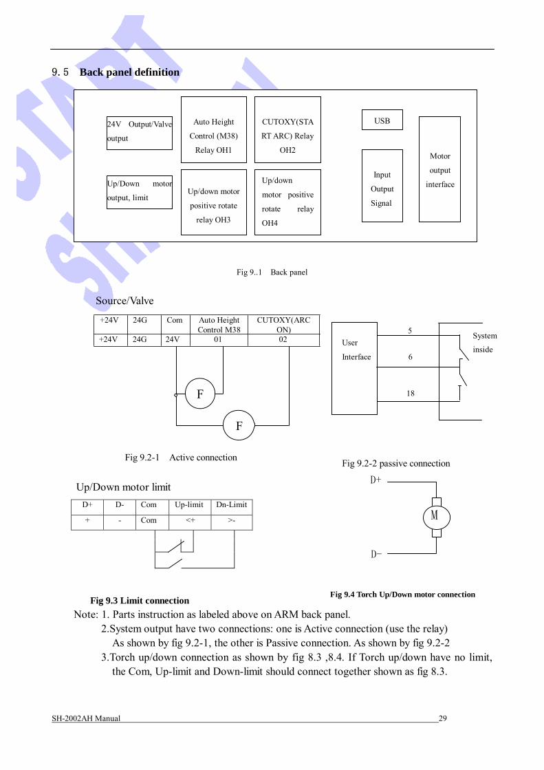
9.5 Back panel definition
24V Output/Valve
output
Up/Down motor
output, limit
Auto Height
Control (M38)
Relay OH1
Up/down motor
positive rotate
relay OH3
CUTOXY(STA
RT ARC) Relay
OH2
Up/down
motor positive
rotate relay
OH4
USB Input
Output
Signal
Motor
output
interface
Fig 9..1 Back panel
Source/Valve
+24V 24G Com Auto Height Control M38
CUTOXY(ARC ON) 5
+24V 24G 24V 01 02
F
F
User
Interface 6
18
System
inside
Fig 9.2-1 Active connection
Up/Down motor limit
Fig 9.2-2 passive connection
D+
M
D-
Fig 9.3 Limit connection Fig 9.4 Torch Up/Down motor connection
Note: 1. Parts instruction as labeled above on ARM back panel. 2.System output have two connections: one is Active connection (use the relay)
As shown by fig 9.2-1, the other is Passive connection. As shown by fig 9.2-2 3.Torch up/down connection as shown by fig 8.3 ,8.4. If Torch up/down have no limit,
the Com, Up-limit and Down-limit should connect together shown as fig 8.3.

SH-2002AH Manual 30
Beijing Flourishing Start Digital Technology Co., Ltd
APPENDIX 1
Function:
Update software instruction
Upgrade software by U disk. Step: 1. Copy the upgrade file to U disk. Attention: The file name only is STARTCNC.EXE. 2. Press the Button “START”(Green) and “STOP”(Red) at one time when power on the system,
until the upgrading interface appear. 3. Insert the U Disk, press F1, system will complete upgrade automatically. During upgrading, system will hint some information.
4. Finish
If operation succeed, it will display succeed information and the beep will have one sound; If failed, it will display failed information and the beep will sound all the while to alarm.
5. Turn off power source, pull out U disk. When you power up again, it is the new software.
Attention:
1. The file’s( STARTCNC.EXE) size don’t over 248K. 2. The reason of upgrade failed more is caused by U disk, if system have not hint the U
disk’s operation course, please instead U disk and try again.
APPENDIX 2
Install Dimension

SH-2002AH Manual 31
Beijing Flourishing Start Digital Technology Co., Ltd