manual of traffic signs and markings (motsam) - part 2 ... · section 1: introduction 1.01 ... the...
TRANSCRIPT
.
DELINEATION ANDHAZARD MARKERS
SECTION 5
Update July 2010

Part 2: Markings CONTENTSFeb 2010%
CONTENTSReference Page Page
Number Date
i.%
.
SECTION 1: INTRODUCTION1.01 General .. .. .. .. .. .. .. .. .. .. .. 1-1 August 20071.02 Non Intersection Pavement Markings .. .. .. .. .. .. .. 1-1 “1.03 Intersection Pavement Markings .. .. .. .. .. .. .. .. 1-1 “1.04 Miscellaneous Pavement Markings .. .. .. .. .. .. .. .. 1-1 “1.05 Delineation and Hazard Markings .. .. .. .. .. .. .. .. 1-2 “1.06 Motorway Pavement Markings .. .. .. .. .. .. .. .. 1-2 “
SECTION 2: PAVEMENT MARKINGS2.01 Centrelines .. .. .. .. .. .. .. .. .. .. .. 2-1 “2.02 Lane Lines .. .. .. .. .. .. .. .. .. .. .. 2-5 June 20092.03 Edge Lines .. .. .. .. .. .. .. .. .. .. .. 2-9 July 20082.04 Diagonal Shoulder Markings .. .. .. .. .. .. .. .. 2-12 August 20072.05 No Overtaking Lines .. .. .. .. .. .. .. .. .. .. 2-14 Feb 2010 2.06 No Overtaking Advance Warning Lines .. .. .. .. .. .. .. 2-16 August 20072.07 Passing Lanes .. .. .. .. .. .. .. .. .. .. 2-19 Feb 20102.08 Markings Ahead of Raised Islands and Medians .. .. .. .. .. .. 2-22 August 2007“2.09 Flush Medians .. .. .. .. .. .. .. .. .. .. 2-26 “2.10 Cycle Lanes .. .. .. .. .. .. .. .. .. .. .. 2-30 July 2008 2.11 Parking .. .. .. .. .. .. .. .. .. .. .. 2-34 July 20082.12 Special Vehicle Parking Areas .. .. .. .. .. .. .. .. 2-38 July 20082.13 Slow Vehicle Bays .. .. .. .. .. .. .. .. .. .. 2-42 Feb 2010
SECTION 3: INTERSECTION PAVEMENT MARKINGS3.01 Intersections - General .. .. .. .. .. .. .. .. .. 3-1 “
3.02 Centrelines at Intersections .. .. .. .. .. .. .. .. .. 3-2 June 2009 3.03 Edge lines at Intersections .. .. .. .. .. .. .. .. .. 3-4 “
3.04 Lane Lines at Intersections .. .. .. .. .. .. .. .. .. 3-8 “ 3.05 Lane Arrows .. .. .. .. .. .. .. .. .. .. .. 3-11 Feb 2010
3.06 Limit Lines .. .. .. .. .. .. .. .. .. .. .. 3-14 June 2009 3.07 Continuity Lines .. .. .. .. .. .. .. .. .. .. 3-16 “3.08 Uncontrolled Intersections .. .. .. .. .. .. .. ... 3-17 “3.09 Give Way Controlled Intersections .. .. .. .. .. .. .. .. 3-21 “3.10 Stop Controlled Intersections .. .. .. .. .. .. .. .. 3-27 “3.11 Traffic Signal Controlled Intersections .. .. .. .. .. .. .. 3-30 “3.12 Approaches to Roundabouts .. .. .. .. .. .. .. .. 3-35 “

CONTENTS Part 2: MarkingsJuly 2010%
CONTENTSReference Page Page
Number Date
ii.%
3.13 Flush Traffic Islands at Intersections .. .. .. .. .. .. ... 3-39 June 20093.14 Left Turn Lanes .. .. .. .. .. .. .. .. .. .. 3-43 “3.15 Right Turn Lanes In Raised Medians .. .. .. .. .. .. .. 3-48 “
3.16 Right Turn Bays .. .. .. .. .. .. .. .. .. .. 3-50 “3.17 Flush Medians at Intersections .. .. .. .. .. .. .. .. 3-55 “3.18 Cycle Lanes at Intersections .. .. .. .. .. .. .. .. 3-59 “
SECTION 4: MISCELLANEOUS PAVEMENT MARKINGS4.01 Pavement Messages and Symbols .. .. .. .. .. .. .. .. 4-1 “4.02 Pedestrian Crossings .. .. .. .. .. .. .. .. .. 4-6 “ 4.03 Railway Level Crossings .. (Section deleted June 2009) .. .. .. 4-14 “4.04 Flashing Red (and Temporary) Signals .. .. .. .. .. .. .. 4-32 “4.05 One- Lane Bridges .. (Figure 4.23 corrected June 2009) .. .. .. .. 4-34 “ 4.06 Raised Pavement Markers.. .. .. .. .. .. .. .. .. 4-37 “4.07 Fire Hydrants .. .. .. .. .. .. .. 4-42 July 20084.08 Profiled Line Marking.. .. .. .. .. .. .. .. .. .. 4-45 Feb 2010
SECTION 5: DELINEATION AND HAZARD MARKERS5.01 Delineation and Hazard Markers - General.. .. .. .. .. .. .. 5-1 “5.02 Hazards Adjacent to The Roadway; including Safety Barriers. .. .. .. .. 5-2 June 2009 5.03 Hazards Within The Roadway .. .. .. .. .. .. .. .. 5-9 July 20105.04 Approaches To Hazards Within The Roadway .. .. .. .. .. .. 5-12 Nov 2004%5.05 Edge Marker Posts .. .. .. .. .. .. .. .. .. .. 5-13 July 20105.06 Linear Delineation Panels .. .. .. .. .. .. .. .. .. 5-18 April 2005
Note: For chevron sight boards refer to MOTSAM Part 1 Section 6: PW-66, PW-67, PW-68 & PW-69.
For motorway markings refer to MOTSAM part 3.

Part 2: Markings DELINEATION AND HAZARD MARKERS%July 2004%
5 - 1
Update: July 2004%
5.01 INTRODUCTION%
5.01.01 GENERALObjects within and immediately adjacent to the road canconstitute a hazard to traffic. Those that cannotreasonably be remov ed or protected require uniform%methods of highlighting.
Hazard markers and signs ensure that driversapproaching such objects have adequate advancewarning to allow proper precautions to be taken.
Devices approved for use to mark hazards on or near theroad include reflectorised markers, painted markings andtraffic signs.
5.01.02 POTENTIAL HAZARDSObjects which may constitute a hazard to traffic include:
! bridge end posts, kerb ends, footpaths, etc,
! ends of sight rails, guardrails and handrails,%
! piers and abutments at underpasses,
! ends of non-mountable kerbs,%
! soffits of underpasses with less than 4.4 m vertical clearance,
! non-frangible service poles and lighting columns,
! ends of medians, safety zones, kerb extensions%and kerb build-outs, and%
! trees with a trunk diameter more than 150 mm.

HAZARDS ADJACENT TO THE ROADWAY Part 2: MarkingsAugust 2007%5 - 2
.%
5.02 HAZARDS ADJACENT TO THE ROADWAY
5.02.01 WIDTH MARKERS%AT GUARDRAILS, BRIDGES & %OTHER WIDTH RESTRICTIONS %
Width markers shall be installed on bridge guardrails, %other guardrails, bridge end posts or other such %width restrictions ONLY if they come within the clear or % trafficable approach width of the highway. %
(a) Width Marker Details:Refer to Figure 5.1
Colour : Three white reflectorised (left hand side) diagonal stripesColour : Three yellow reflectorised(right hand side) diagonal stripesBackground : Matt black.Height : 900 mmWidth : 150 mm (min.)
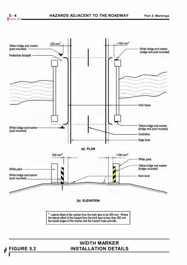
(b) Installation of Width Markers:Refer to Figure 5.4
Width markers shall be attached:> On, or in front of, non-frangible width restrictions (eg. concrete bridge ends) in which case the front
face of the restriction shall be painted white. > In the case of guardrails, on the guardrail post or on posts hard behind the guardrail. %
The top of the marker should be a minimum of 1.0 mabove the road surface.
The markers shall be erected on one or both sides ofthe road as applicable and facing oncoming traffic.
White markers shall be used on the left hand side of theroad and yellow markers used on the right.
The diagonal stripes on the markers shall slope%downward towards the road.
5.02.02 SERVICE POLES AND OTHERISOLATED ROADSIDE%HAZARDS
(a) Hazard Marker Details:Hazard markers shall be as described below:
Refer to Figure 5.3
Colour : Two 100 mm dia. reflectorisedwhite discs
Background : Matt black.Height : 375 mmWidth : 150 mm
(b) Hazard Marker Location:Refer to Figure 5.4
Hazard markers shall be used to mark hidden objects %(eg depressed culverts), and upright items if there is a %reasonable probability of it being a hazard (eg isolated%
....
. %. %
* Traversable means that the ground surface%shape is such as to permit the driver of an%errant vehicle to regain control, ie. the ground%has a relatively smooth surface and a slope of%# 1:6.%
They are not normally required in urban areas.%
NOTE: Marking is not required for roadside%hazards protected by approved road safety%barriers or for frangible type service poles.%
(c) Installation of Hazard Markers:Refer to Figure 5.4.
The surface of a haz ard does not normally needpainting white unless its size, shape or position makes it particularly vulnerable.
A hazard marker shall be attached directly to the obstacleor erected on a timber post immediately in front of iit. Themarker should be positioned so that its lower edge is 1.2m above ground level.
Hazards on both sides of the highway shall bemarked as appropriate.
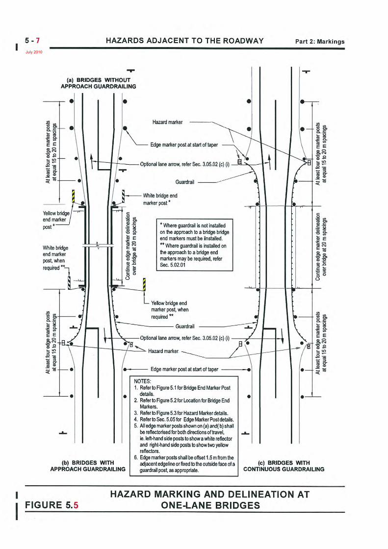
5.02.03 ONE-LANE BRIDGESRefer to Figure 5.6
Special attention should be paid to one-lane bridges and%one-lane sections of road. These require a combination%of signs, markin gs and haz ard markers to identify the%particularly haz ardous situations that occur when a%two-lane road transitions into a one-lane section of road.%
For markings on one-lane bridges refer to Section 4.05.
.unexpected object on a curve.)
Hazard markers are only required if the object is within4 - 6 metres of the relevant lane, the intervening area istraversible* by vehicles and it is not already shielded bysomething else (eg guardrail, kerb, longitudinal drain.)

Part 2: Markings HAZARDS ADJACENT TO THE ROADWAYAugust 2007
5 - 3
WIDTH MARKERS FIGURE 5.1
HAZARDS ADJACENT TO THE ROADWAY Part 2: MarkingsAugust 2007%5 - 4
WIDTH MARKER %
FIGURE 5.2 INSTALLATION DETAILS %%
%

Part 2: Markings HAZARDS ADJACENT TO THE ROADWAYJune 1994
5 - 5
HAZARD MARKERS FIGURE 5.3

HAZARDS WITHIN THE ROADWAY Part 2 MarkingsAugust 20075 - 6
HAZARD MARKER:To mark hidden objects (e.g Depressed culverts) and upright items if there is reasonable probability of it being a hazard (e.g isolated, unexpected object on a curve).(refer part 5 fig. 5.3).
Only required if:Object is within 4-6m of the relevant lane, andIt is not already sheilded by something else (e.g guardrail, kerb,longitudinal drain), andThe intervening area is traversible. Refer section 5.02.02(b).It is not normally necessary to paint the objectwhite.
Narrowest point
WIDTH MARKER:Install at narrowest point, but only if within TrafficableCarriageway / Clear Approach width.Use on one or both sides as necessary.(Refer Part 5 Fig 5.1)
FIGURE 5.4 WIDTH MARKERS & HAZARD MARKERS
Trafficable Carriageway or Clear Approach width if no shoulders
Typically 1.2m - 3.0m.(Refer Part 2 Fig 5.05)
Use A Hazard Marker,on all guardrail end
terminals unless itqualifies for a width
marker, in which caseuse that instead.
(Refer Part 5 Fig 5.3).
Hatch Shoulder if widerthan 2.0m.
(Refer Part 2 Fig 2.04).
EOS EL CL EL EOS
EMP
EMP
July 2010
Part 2: Markings HAZARDS ADJACENT TO THE ROADWAYJune 2009
5 - 8
%%
%
5.02a DELINEATION OF SAFETY BARRIERS
5.02.04 MEDIAN BARRIERS When median barriers are installed within 2.5 m of the right hand edgeline of the carriageway, they should befitted with yellow reflectors or reflective tape mounted on top of the barrier.This is not normally required where highway lighting isinstalled. Size of reflectors : 50 sq cm minimum. Colour of reflectors : Yellow. Spacing of reflectors : 10 m +/- 2 m.
Note: In the case of wire rope barriers, the reflector should be mounted at the top of the post. Delineation is enhanced when the posts are powder-coated white.
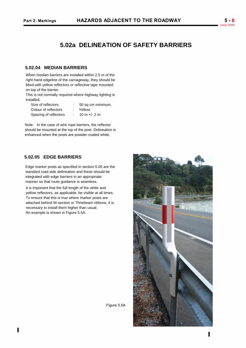
5.02.05 EDGE BARRIERS
Edge marker posts as specified in section 5.05 are thestandard road side delineation and these should beintegrated with edge barriers in an appropriatemanner so that route guidance is seamless.
It is important that the full length of the white and
yellow reflectors, as applicable, be visible at all times.To ensure that this is true where marker posts are attached behind W-section or Thriebeam ribbons, it isnecessary to install them higher than usual. An example is shown in Figure 5.5A.
Figure 5.5A

Part 2: Markings HAZARDS WITHIN THE ROADWAYJuly 2010
5 - 9
5.03 HAZARDS WITHIN THE ROADWAY
5.03.01 HAZARDS BETWEEN LANESCARRYING TRAFFIC IN THESAME DIRECTION
A hazard which may be passed on either side by traffictravelling in the same direction shall be marked andsigned unless traffic is protected from the hazard.Sometimes it may be necessary to mark protectedhazards also.
Items of road furniture such as median barrier terminalscan also be considered as potential hazards within theroadway and should be marked accordingly.
Refer to Sections 5.04.02 and 2.08.03 for marking detailsof approaches to hazards between lanes carrying trafficin the same direction.
The surface of the hazaard which faces approaching trafficshall be white up to a height of 1.7 m above road level.
The PW - 5 DIVERGE traffic sign may be used, but dueto their visibility obstruction, only if other cues fail.
5.03.02 HAZARDS BETWEEN LANESCARRYING OPPOSINGTRAFFIC
A hazard which traffic must pass on the left, eg. an objectlocated at the centre of the roadw ay of a conv entionaltwo-lane road, shall be marked as follows:
! regulatory RG - 17 KEEP LEFT signs as specifiedfor traffic islands in Part I of this manual shall beprovided,
! where the hazard is bordered by kerbing and thekerb face is less than 3 m from the hazard, orwhere the hazard is not bordered by kerbing, thehazard shall be marked with paint and hazardmarkers on the left hand edges,
! marking of the hazard is not required where barrierprotection has been provided,
! surfaces of the hazard which face approachingtraffic shall be white up to a height of 1.7 m aboveroad level,
! hazard markers shall be applied to the left handedges of the hazard, and
! where the object constitutes the right hand hazardof a pair of end hazards (e.g. an underpass ortunnel), bridge end markers shall be erected asdescribed in Section 5.02.01.
Refer to Sections 2.08.02 and 5.04.03 for pavementmarkings on the approaches to haz ards between lanescarrying opposing traffic.
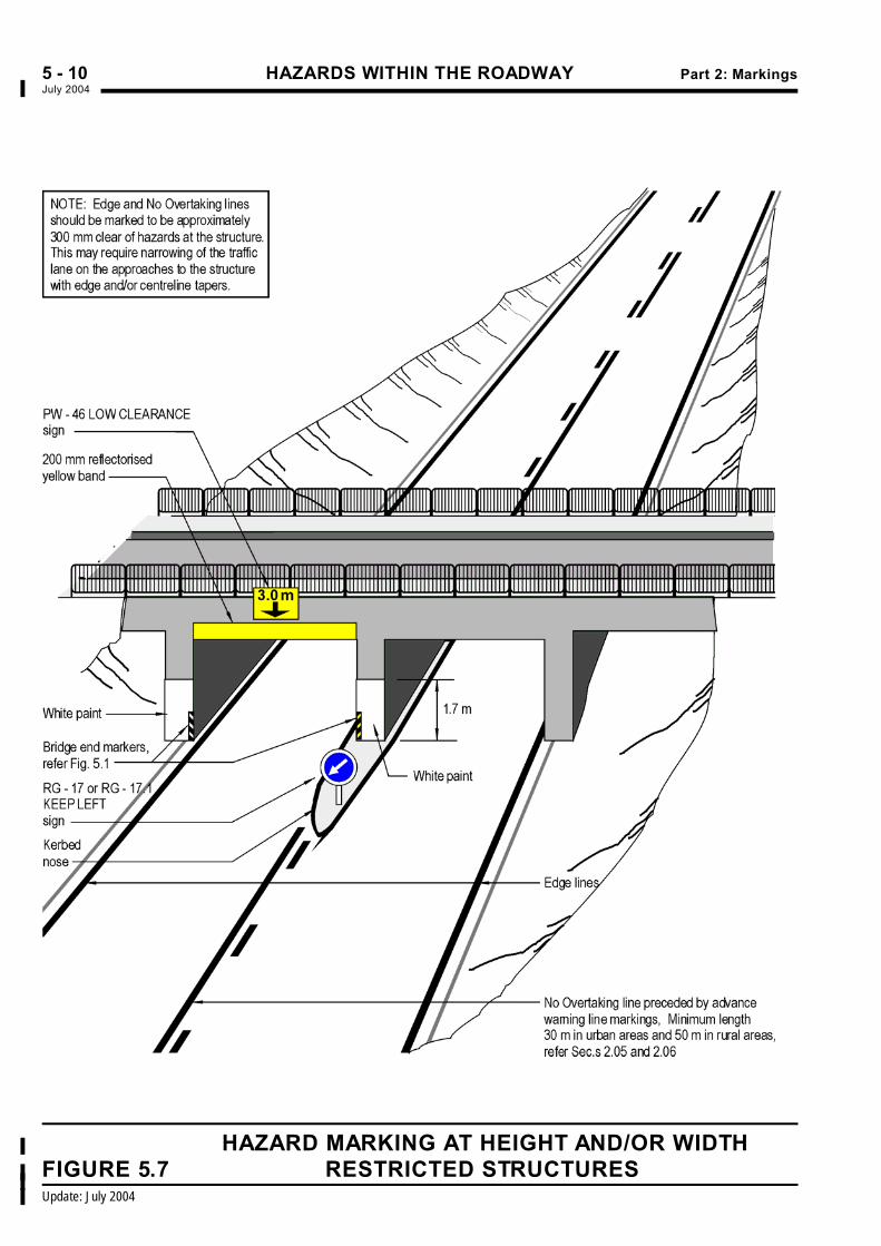
5.03.03 STRUCTURES WITH LOWOVERHEAD CLEARANCE
Refer to Figures 5.7 and 5.8
Where PW - 46 Low C learance signs are erected onstructures a 200 mm wide continuous yellow line shall bemarked along the soffit line of the structure.
Where the soffit is of variable height such as at an archstructure, additional reflectoris ed white arrow s shallindicate the points where clearance is a minimum. Referalso to Part I of this manual for details of the PW - 46sign.
5.03.04 CRASH CUSHIONS(a) Where a crash cushion is located on a median and approaching traffic must therefore keep to the left of it, a RG-17 Keep Left sign should be installed unless other installations negate the need for this.
approaching traffic (b) Where a crash cushion is located in a situation where
approaching traffic may pass to either side of it, eg: at a motorway offramp, the nose cone or leading face must be marked with black and reflectorised yellow stripes 100mm wide as shown in figure 5.6 below.
Note: These dimensions may be adjusted to suit the crash cushion to which the marking is affixed.
Figure 5.6
HAZARDS WITHIN THE ROADWAY Part 2: MarkingsJuly 2004%5 - 10
HAZARD MARKING AT HEIGHT AND/OR WIDTH%
FIGURE 5.7 RESTRICTED STRUCTURES%%
Update: July 2004%

Part 2: Markings HAZARDS WITHIN THE ROADWAYJuly 2004%5 - 11
HAZARD MARKING AT STRUCTURES WITH%
VARYING SOFFIT HEIGHT FIGURE 5.8%

APPROACHES TO HAZARDS WITHIN THE ROADWAY Part 2: MarkingsNovember 2004%5 - 12
Correction: November 2004%
5.04 APPROACHES TO HAZARDS WITHIN THE ROADWAY
5.04.01 GENERALAll objects located within the roadway and constituting ahazard to traffic require approach markings to guidetraffic past the object.
The markings shall take the form of reflectorised w hite%lines and stripes.
Approach markings for one way traffic situations shouldbe marked differently from those where opposing trafficflows occur.
If approach speeds are high, the length of marking shouldbe increased.
5.04.02 HAZARDS BETWEEN LANESCARRYING TRAFFIC IN THESAME DIRECTION
The approach marking shall consist of two divergingreflectorised w hite lines enclos ing a broad chev ron%pattern of reflectorised white bars (chevrons).%
The pavement shall be marked in the same manner as%markings ahead of traffic islands separating div erging%traffic. %
Refer to Section 2.08.03 and Figure 2.8.
(a) RuralColour : Reflectorised whiteBorder Width : 200 mmBar Width : 900 mmBar Spacing : 10.0 mBar slope : 2:1Length : 50 m minimum
(b) UrbanColour : Reflectorised whiteBorder Width : 100 mmBar Width : 600 mmBar Spacing : 6.0 mBar slope : 2:1Length : 30 m minimum
5.04.03 HAZARDS BETWEEN LANESCARRYING OPPOSINGTRAFFIC
For hazards which traffic must pass on the left approachmarking shall be in the form of a no-overtaking line plusadvance w arning line or in the case of a multi lanehighway a double reflectorised yellow centreline.
The pavement shall be marked in the same manner as fortraffic islands separating opposing traffic.
Refer to Section 2.08.02 and Figure 2.7.
Colour : Reflectorised whiteWidth : 100 mm, offset 100 mm from white
or double yellow centreline%Stripe : ContinuousLength : 50 m min, rural
30 m min, urban.
Part 2: Markings EDGE MARKER POSTSJune 2009 %5 - 13
.%
Road Type Treatment
PostSpacing,refer tosection
Min.AADT
UnsealedRoad Total Route 5.05.05 500
Sealed Road IsolatedSections 5.05.05 100
Sealed Road Total Route 5.05.05 500
Sealed Road Total Route 5.05.06 1500
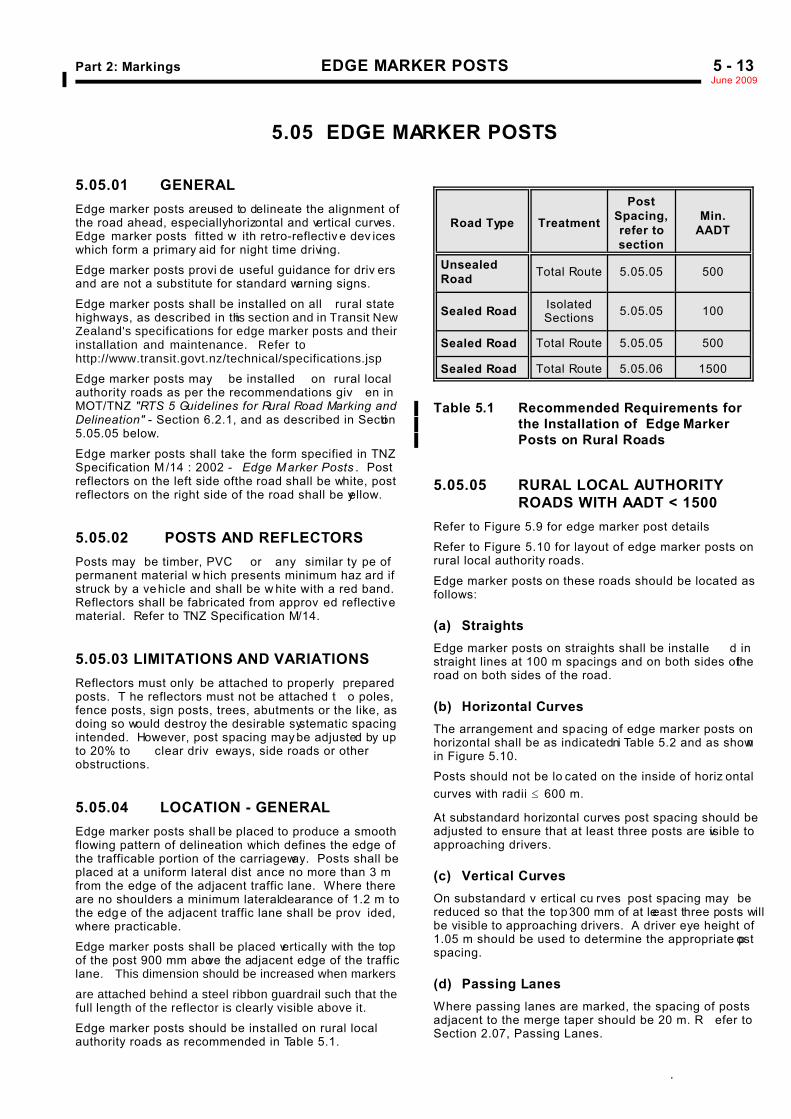
5.05 EDGE MARKER POSTS
5.05.01 GENERALEdge marker posts are used to delineate the alignment ofthe road ahead, especially horizontal and vertical curves.Edge marker posts fitted w ith retro-reflectiv e dev iceswhich form a primary aid for night time driving.
Edge marker posts provi de useful guidance for driv ersand are not a substitute for standard warning signs.
Edge marker posts shall be installed on all rural statehighways, as described in this section and in Transit NewZealand's specifications for edge marker posts and theirinstallation and maintenance. Refer tohttp://www.transit.govt.nz/technical/specifications.jsp
Edge marker posts may be installed on rural localauthority roads as per the recommendations giv en inMOT/TNZ "RTS 5 Guidelines for Rural Road Marking andDelineation" - Section 6.2.1, and as described in Section5.05.05 below.
Edge marker posts shall take the form specified in TNZSpecification M /14 : 2002 - Edge Marker Posts . Postreflectors on the left side of the road shall be white, postreflectors on the right side of the road shall be yellow.
5.05.02 POSTS AND REFLECTORSPosts may be timber, PVC or any similar ty pe ofpermanent material w hich presents minimum haz ard ifstruck by a vehicle and shall be w hite with a red band.Reflectors shall be fabricated from approv ed reflectivematerial. Refer to TNZ Specification M/14.
5.05.03 LIMITATIONS AND VARIATIONSReflectors must only be attached to properly preparedposts. T he reflectors must not be attached t o poles,fence posts, sign posts, trees, abutments or the like, asdoing so would destroy the desirable systematic spacingintended. However, post spacing may be adjusted by upto 20% to clear driv eways, side roads or otherobstructions.
5.05.04 LOCATION - GENERALEdge marker posts shall be placed to produce a smoothflowing pattern of delineation which defines the edge ofthe trafficable portion of the carriageway. Posts shall beplaced at a uniform lateral dist ance no more than 3 mfrom the edge of the adjacent traffic lane. Where thereare no shoulders a minimum lateral clearance of 1.2 m tothe edge of the adjacent traffic lane shall be prov ided,where practicable.
Edge marker posts shall be placed vertically with the topof the post 900 mm above the adjacent edge of the trafficlane. This dimension should be increased when markers
are attached behind a steel ribbon guardrail such that the %full length of the reflector is clearly visible above it.%
Edge marker posts should be installed on rural local%authority roads as recommended in Table 5.1.%
Table 5.1 Recommended Requirements for%the Installation of Edge Marker%Posts on Rural Roads%
5.05.05 RURAL LOCAL AUTHORITYROADS WITH AADT < 1500
Refer to Figure 5.9 for edge marker post details
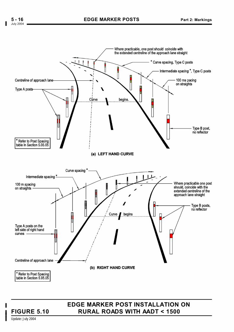
Refer to Figure 5.10 for layout of edge marker posts onrural local authority roads.
Edge marker posts on these roads should be located asfollows:
(a) StraightsEdge marker posts on straights shall be installe d instraight lines at 100 m spacings and on both sides of theroad on both sides of the road.
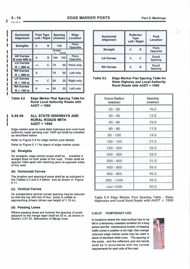
(b) Horizontal CurvesThe arrangement and spacing of edge marker posts onhorizontal shall be as indicated in Table 5.2 and as shownin Figure 5.10.
Posts should not be lo cated on the inside of horiz ontalcurves with radii # 600 m.
At substandard horizontal curves post spacing should beadjusted to ensure that at least three posts are visible toapproaching drivers.
(c) Vertical CurvesOn substandard v ertical cu rves post spacing may bereduced so that the top 300 mm of at leeast three posts willbe visible to approaching drivers. A driver eye height of1.05 m should be used to determine the appropriate postspacing.
(d) Passing LanesWhere passing lanes are marked, the spacing of postsadjacent to the merge taper should be 20 m. R efer toSection 2.07, Passing Lanes.
WWWWWFeb 2010

July 2010
EDGE MARKER POSTS Part 2: MarkingsJuly 2004%5 - 16
EDGE MARKER POST INSTALLATION ON%
FIGURE 5.10 RURAL ROADS WITH AADT < 1500%%
Update: July 2004%
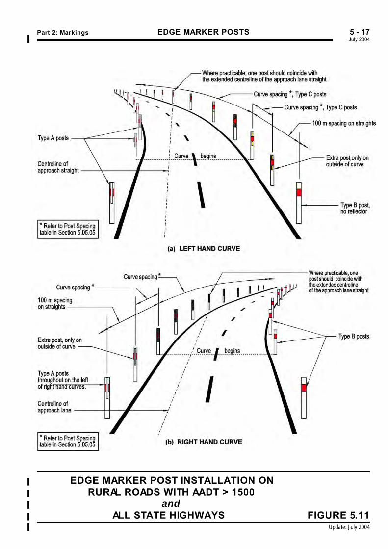
Part 2: Markings EDGE MARKER POSTSJuly 2004%5 - 17
EDGE MARKER POST INSTALLATION ON%
RURAL ROADS WITH AADT > 1500%
and %
ALL STATE HIGHWAYS FIGURE 5.11%
Update: July 2004%
Disclaimer: Land Transport New Zealand has endeavoured to ensure the material in this document is technically accurate and reflects legal requirements. However, the document does not override governing legislation. Land Transport NZ does not accept liability for any consequences arising from the use of this document. If the user of this document is unsure whether the material is correct, they should make direct reference to the relevant legislation and contact Land Transport NZ.
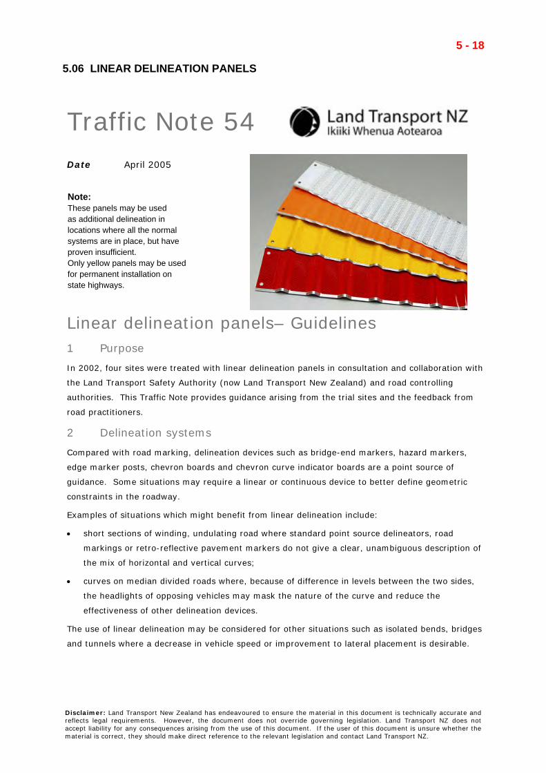
Traffic Note 54 Date April 2005
.
Linear delineation panels– Guidelines 1 Purpose
In 2002, four sites were treated with linear delineation panels in consultation and collaboration with
the Land Transport Safety Authority (now Land Transport New Zealand) and road controlling
authorities. This Traffic Note provides guidance arising from the trial sites and the feedback from
road practitioners.
2 Delineation systems
Compared with road marking, delineation devices such as bridge-end markers, hazard markers,
edge marker posts, chevron boards and chevron curve indicator boards are a point source of
guidance. Some situations may require a linear or continuous device to better define geometric
constraints in the roadway.
Examples of situations which might benefit from linear delineation include:
• short sections of winding, undulating road where standard point source delineators, road
markings or retro-reflective pavement markers do not give a clear, unambiguous description of
the mix of horizontal and vertical curves;
• curves on median divided roads where, because of difference in levels between the two sides,
the headlights of opposing vehicles may mask the nature of the curve and reduce the
effectiveness of other delineation devices.
The use of linear delineation may be considered for other situations such as isolated bends, bridges
and tunnels where a decrease in vehicle speed or improvement to lateral placement is desirable.
5 - 18
5.06 LINEAR DELINEATION PANELS
Note: These panels may be used as additional delineation in locations where all the normalsystems are in place, but have proven insufficient.Only yellow panels may be usedfor permanent installation onstate highways.

Traffic Note 54 – page 2 of 2
3 Linear delineation panels
The linear delineation used in the trials comprised panels approximately 870mm long, 100mm wide
with a repeating raised lateral ridge 8.6mm high approximately every 57mm. Each panel was
constructed of retro-reflective material permanently bonded to an aluminium substrate. The shape
provides retro-reflection across a wide range of entrance and observation angles.
The panels are designed for installation on rigid structures including W-section steel traffic barriers,
concrete median barriers, movable lane barriers and sight rails and conform to the shape and
orientation of these structures.
4 Spacing between adjacent delineation panels
In some countries linear delineation panels are installed with no gaps. The linear delineation panel
trials indicated gaps are required between adjacent panels in order to give a good indication of the
road alignment. A gap larger than half a panel length (440mm) and smaller than 2 panel lengths
(1740mm) provided good visual cues. The radius of the curve will affected the spacing; where
smaller radius curves will need smaller gaps and larger radius curves greater gaps.
5 Use of colours
Consultation with the industry and road controlling authorities provided the following consensus on
the colours and use of the various linear delineation panels.
Panel colour Use
white sight boards
yellow
fluorescent yellow
in association with other permanent warning devices (eg
curve warning signs, chevron boards etc)
alternating white and fluorescent
orange
work zone barrier delineation
alternating red and white rail rolling stock
6 Installation issues
The panels provide an almost continuous indication of the road alignment and it is important the
rigid structures on which they are installed substantially conform to the road alignment – both
vertically and horizontally. This may require some realignment of existing structures.
Where used as curve delineation devices the linear delineation panels should be used to
supplement other appropriately installed permanent warning signs. A careful review of other
delineation devices along the treated length of road should then be carried out. Those that will
remain must be compatible with the permanent warning signs and the linear delineation and the
combination must provide a clear and unambiguous message to drivers.
5 - 19