manualdigital locking cylinder 3061 - simonsvoss€¦ · · 2017-11-034.1fd version (standard ......
TRANSCRIPT

ManualDigital Locking Cylinder 3061
08.2017

Contents1 Intended use.................................................................................................................................... 4
2 Safety instructions.......................................................................................................................... 5
3 General information on System 3060............................................................................................ 73.1 Product description................................................................................................................. 73.2 Locking cylinder design .......................................................................................................... 83.3 Half cylinder design ................................................................................................................ 93.4 Opening and locking from the outside.................................................................................... 93.5 Opening and locking from the inner side ............................................................................. 10
4 System 3060 designs.................................................................................................................... 114.1 FD version (Standard) .......................................................................................................... 124.2 HZ version (Standard) .......................................................................................................... 124.3 ............................................................................................................................................. 124.4 ZK version ............................................................................................................................ 124.5 version for steel and fire retardant doors.............................................................................. 124.6 TS version ............................................................................................................................ 134.7 MR option ............................................................................................................................. 134.8 MS version ........................................................................................................................... 134.9 SKG or VdS versions (SZ) ................................................................................................... 134.10 AP version ............................................................................................................................ 144.11 AP2 Version ......................................................................................................................... 154.12 CO version ........................................................................................................................... 154.13 WP Version (FD) .................................................................................................................. 154.14 WP version (HZ/CO/AP)....................................................................................................... 164.15 SW version (CO) .................................................................................................................. 164.16 VR version (HZ).................................................................................................................... 164.17 DK version (HZ).................................................................................................................... 164.18 WN version (HZ)................................................................................................................... 164.19 DM version ........................................................................................................................... 164.20 Hybrid-Version...................................................................................................................... 174.21 Extra lengths ........................................................................................................................ 174.22 Examples of locking cylinder use ......................................................................................... 17
5 Installation instructions................................................................................................................ 185.1 General instructions ............................................................................................................. 185.2 Programming the locking cylinder ........................................................................................ 18
ManualDigital Locking Cylinder 3061
2 / 44SimonsVoss Contents

5.3 Installation variants............................................................................................................... 195.3.1 Installation of double thumb-turn cylinders (except types .AP/.SKG/.VdS) .............. 195.3.2 Fitting an anti-panic cylinder...................................................................................... 215.3.3 Installation of SKG/VdS cylinders.............................................................................. 245.3.4 Half Cylinder DK/MR ................................................................................................. 255.3.5 Installing Swiss Round .............................................................................................. 27
6 System 3060 audible signals ....................................................................................................... 286.1 Battery warnings................................................................................................................... 286.2 Battery warning for transponders ......................................................................................... 30
7 System 3060 battery replacement ............................................................................................... 317.1 General instructions ............................................................................................................. 317.2 Battery life ............................................................................................................................ 317.3 Emergency battery procedure .............................................................................................. 31
7.3.1 Storage mode (G1).................................................................................................... 327.3.2 Freeze mode (G2) ..................................................................................................... 32
7.4 Procedure............................................................................................................................. 337.5 Procedure for outer thumb turn (MH cylinder)...................................................................... 34
8 Maintenance, cleaning and disinfection ..................................................................................... 36
9 Areas of use................................................................................................................................... 379.1 General................................................................................................................................. 379.2 Fire doors ............................................................................................................................. 379.3 Doors along rescue routes ................................................................................................... 379.4 Installation outdoors ............................................................................................................. 37
10 Accessories ................................................................................................................................... 3810.1 Thumb-turns ......................................................................................................................... 3810.2 Core extraction protection adapter (Z4.KA.SET).................................................................. 3810.3 Core extraction protection extension for SKG/VdS cylinders (Z4.KA.SET2)........................ 3810.4 Core extraction protection extension for SKG/VdS cylinders (Z4.KA.SET2.IT) ................... 3810.5 Tool ...................................................................................................................................... 3810.6 Battery set ............................................................................................................................ 39
11 Data sheets .................................................................................................................................... 4011.1 Locking cylinder.................................................................................................................... 4011.2 Half cylinder.......................................................................................................................... 41
12 Declaration of conformity............................................................................................................. 43
13 Help & Contact .............................................................................................................................. 44
ManualDigital Locking Cylinder 3061
3 / 44SimonsVoss Contents

ManualDigital Locking Cylinder 3061
4 / 44SimonsVoss 1 | Intended use
1 Intended useDigital SimonsVoss Locking Cylinder are installed in designated door locks,such as DIN mortise locks, to integrate them into a digital locking system.Digital half cylinders can also be operated in optionally availableSimonsVoss padlocks.The digital Locking Cylinder may only be used for its intended purpose in adesignated door locking device. No other use is permitted.Digital Locking Cylinders are available in various lengths. The selection ofthe proper size is of significance. The length of the locking cylinder isprinted on the packaging and can be measured at any time. If the cylinderis too short, the handles cannot be fitted. If the cylinder is too long, it maybe ripped out of the locking device. The may not protrude more than 3 mmon each side of the door to ensure proper operation.The product may not be changed in any way, other than in compliance withthe changes described in the instructions.

ManualDigital Locking Cylinder 3061
5 / 44SimonsVoss 2 | Safety instructions
2 Safety instructionsWarning: – Access through a door may be blocked due to an incorrectly
installed or incorrectly programmed Locking Cylinder.SimonsVoss Technologies GmbH is not liable for consequencesof incorrect installation, such as denied access to injured persons,physical damage or any other losses.
– The batteries used in the digital Locking Cylinder may pose a fireor burn hazard if handled incorrectly. Do not recharge, open, heator burn these batteries. Do not short-circuit batteries.
– When used in combination with panic locks, after installation, youmust ensure that all parts of the locking system are fully functionaland the mortise lock panic function is guaranteed to work.
– The anti-panic cylinder may only be fitted into locks in which it isexpressly approved for use. Please also refer to the lockmanufacturer's information/documentation.
– If the anti-panic lock is used in non-approved locks, the escapedoor function may malfunction and no longer be triggered. ContactSimonsVoss Technologies GmbH for more information on use inanti-panic locks.
– Do not activate the anti-panic lock before it is fitted as there is arisk of injury from the cam springing back.
– As per European standard EN 179, Appendix C, all components inthe anti-panic cylinder locking mechanism must be checked atintervals no greater than one month to ensure that all parts in thelocking mechanism are in satisfactory working order as part oflocking device maintenance.
Important: – SimonsVoss Technologies GmbH accepts no liability for damagecaused to doors or components due to incorrect fitting orinstallation.
– The SimonsVoss Locking Cylinder may only be used for itsintended purpose: opening and locking doors. No other use ispermitted.
– Only trained specialists may install the cylinder.– Do not allow the cylinder to come into contact with oil, paint or
acids.– Use the .WP version when installing outdoors.– The inside Locking Cylinder thumb-turn features a protection
rating of IP40. This is why it is important to ensure that the insidethumb-turn does not come into contact with water.
– Both knobs are freely rotating in anti-panic cylinders and can onlybe engaged using an authorised ID medium.

ManualDigital Locking Cylinder 3061
6 / 44SimonsVoss 2 | Safety instructions
– When used outdoors, the anti-panic cylinder is no longerguaranteed to function at temperatures under - 20 °C or over +50 °C.
– A functional test must be performed without fail after installing theanti-panic cylinder or replacing its batteries.
– The WP variant must be installed when an anti-panic cylinder isused outdoors.
– We reserve the right to make modifications or further technicaldevelopments.
– This documentation has been compiled based on the bestknowledge available to us. However, errors cannot be ruled out.No liability is accepted in such cases.
– Should there be differences in the content of other languageversions of this documentation, the German version applies incases of doubt.
– All instructions must be followed precisely during installation. Theperson installing the system should hand these instructions aswell as any maintenance instructions over to the user.
– For security reasons, the locking system password must consist ofat least 8 characters. The code length for digital locking cylindersin both System 3060/3061 and MobileKey) is 2168 bit.
Instructions on batteryreplacement
– Only trained specialists may replace the battery.– Damage may be caused to the Locking Cylinder if you reverse the
polarity.– Only use batteries which have been approved by SimonsVoss.– The cylinder must always be operated with two batteries.– Dispose of old and used batteries in the proper manner and store
them out of children's reach.– Always replace both batteries when changing batteries.– Do not touch the contacts on the new batteries with your hands
when replacing the old ones. Use clean gloves free of fat orgrease to handle the battery.
– When replacing the batteries, make sure that the electronics arenot subject to mechanical load and are not damaged in any otherway.
– Only use the SimonsVoss installation/battery key(Z4.SCHLUESSEL) to replace the battery.

ManualDigital Locking Cylinder 3061
7 / 44SimonsVoss 3 | General information on System 3060
3 General information on System 3060
3.1 Product descriptionThe SimonsVoss Digital Locking System 3060 is an electronic version of amechanical locking system with the functions of a typical access controlsystem.Digital Locking Cylinder 3061 and the digital half cylinder are a maincomponent in the locking and access control system, where radiocommunication replaces the mechanical authentication of a conventionalkey.This product description details both the locking cylinder and the halfcylinder. The design and operating mode of the two products arecomparable in many respects. Any differences between the two productsand different versions are pointed out in the corresponding sections.'Locking cylinder' is taken to mean both 'locking cylinder' and 'half cylinder'in this document unless explicitly stated otherwise or taken out of context.Data are transmitted for authentication using a transponder (25kHzinductive) or a smart card featuring the RFID standard MIFARE© Classic orMIFARE© DESFire.Refer to the respective manuals for details about smart card products (SC).This description mentions the smart card cylinder, but does not describe itin any detail.The locking cylinder is supplied in different versions and meets differentprofile standards, such as DIN 18252/EN1303, so that almost any lockanywhere in the world can be retrofitted with this cylinder. Digital LockingCylinder 3061 has much to offer – greater security, greater flexibility, lowercosts, network-ready without any wiring on the door or frame and less timeand effort required for installation.Digital Locking Cylinder 3061 is powered by two batteries in a redundantsystem. Cylinders operate as stand-alone components thanks to thisintegrated power supply, which also means there is no need to wire doors.An intelligent battery warning system also increases reliability.The SimonsVoss system elements are not configured before delivery fromthe factory. They are first assigned to a locking system during initialprogramming. This makes it easier for stock keeping and makes productmanagement simpler.Thanks to modularity, all locking cylinders are seamlessly integrated intothe SimonsVoss System 3060 and, like all SimonsVoss components, theycan be programmed using the locking plan software. Other authenticationcomponents, such as Pin Code Keypad 3068, Biometric Reader Q3008 orCompact Reader 3078, can be connected as a wireless element. If thesystem is extended at a later stage, cylinders can be networked withoutwiring and managed in an online interconnected system.

ManualDigital Locking Cylinder 3061
8 / 44SimonsVoss 3 | General information on System 3060
The locking cylinders are provided with two different firmware generations –G1 and G2. G2 features a more efficient communication protocol than G1.It will allow you to create larger, more efficient locking systems.Authorisations are written both on the locking cylinder and the transponder,thus delivering greater flexibility for programming. A G2 system can alsoform a virtual network, i.e. authorisations and blocking lists are written onthe transponder and transmitted into the locking system. Refer to the G2manual for more details.
3.2 Locking cylinder design
1. Inside thumb-turn2. Batteries/electronics3. Actuator4. Drilling protection5. Outer thumb-turn

ManualDigital Locking Cylinder 3061
9 / 44SimonsVoss 3 | General information on System 3060
3.3 Half cylinder design
1. Actuator2. Electronics3. Batteries4. Thumb-turn
3.4 Opening and locking from the outsideWith freely rotatinglocking cylinders (FD)
The outer and inside thumb-turn rotate freely when not activated inthe freely rotating Locking Cylinder, meaning it is not possible to openor lock the door without a valid ID medium. Identify yourself with yourvalid ID medium on the outer thumb-turn to activate the cylinder. If theID medium is authorised, an audible signal will sound twice, the blueLED will flash twice and the locking cylinder will engage ready toopen. Turn the outer thumb-turn in the direction of locking or opening.You have about five seconds to do so. The engage time can beconfigured. A single audible signal will then sound and the outer orinside thumb-turn will rotate freely again. Ensure that the outside orinside locking cylinder thumb-turn rotates freely again after thethumb-turn has been engaged ready for use.
NOTICE If the user has an ID medium which is not authorised for use at that particu-lar moment due to the time zone plan, a single audible signal will sound.The cylinder will not engage, so the outer or inside thumb-turn continues torotate freely and the user cannot open the door. You need to configure thisresponse separately in third-party systems.

ManualDigital Locking Cylinder 3061
10 / 44SimonsVoss 3 | General information on System 3060
3.5 Opening and locking from the inner sideWith freely rotatinglocking cylinders (FD)
The outer and inside thumb-turn rotate freely when not activated inthe freely rotating Locking Cylinder, Doors can also only be opened orlocked on the outside using an ID medium on the inside thumb-turn.
With non-freelyrotating lockingcylinders (FD)
Locking Cylinders which are permanently engaged for use can beoperated from the inside without a ID medium. In this case, the doorcan be opened and closed using the inside thumb-turn without anauthorised ID medium.
ManualDigital Locking Cylinder 3061
11 / 44SimonsVoss 4 | System 3060 designs
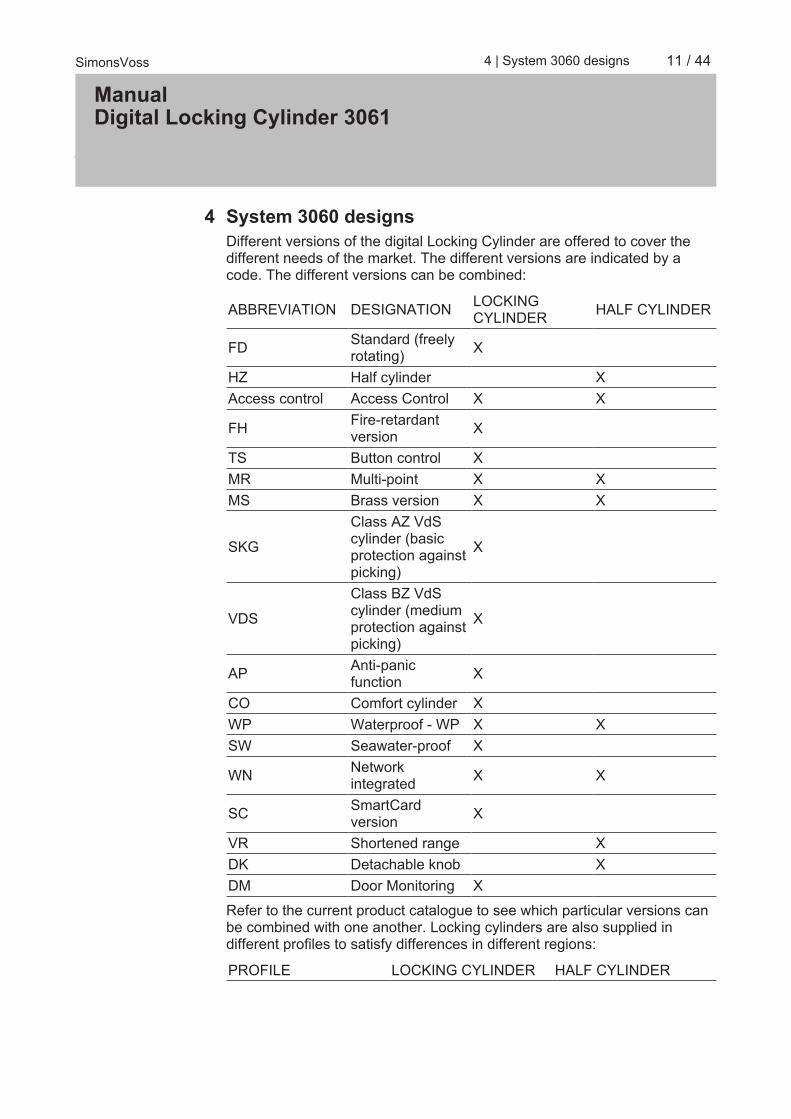
4 System 3060 designsDifferent versions of the digital Locking Cylinder are offered to cover thedifferent needs of the market. The different versions are indicated by acode. The different versions can be combined:
ABBREVIATION DESIGNATION LOCKINGCYLINDER HALF CYLINDER
FD Standard (freelyrotating) X
HZ Half cylinder XAccess control Access Control X X
FH Fire-retardantversion X
TS Button control XMR Multi-point X XMS Brass version X X
SKG
Class AZ VdScylinder (basicprotection againstpicking)
X
VDS
Class BZ VdScylinder (mediumprotection againstpicking)
X
AP Anti-panicfunction X
CO Comfort cylinder XWP Waterproof - WP X XSW Seawater-proof X
WN Networkintegrated X X
SC SmartCardversion X
VR Shortened range XDK Detachable knob XDM Door Monitoring X
Refer to the current product catalogue to see which particular versions canbe combined with one another. Locking cylinders are also supplied indifferent profiles to satisfy differences in different regions:
PROFILE LOCKING CYLINDER HALF CYLINDER

ManualDigital Locking Cylinder 3061
12 / 44SimonsVoss 4 | System 3060 designs
Standard Euro profilecylinder as per DIN18252/EN1303
X X
Scandinavian Oval XBritish oval XSwiss Round X X
Locking Cylinders are also offered in mortise and rim cylinder models forAmerican door profiles.
4.1 FD version (Standard)Locking Cylinder freely rotating on both sides.The .FD double thumb-turn cylinder is available from a length of 30-30 mm.
4.2 HZ version (Standard)The standard version of the half cylinder.
4.3
4.4 ZK versionDesign is similar to standard version but with access logging and time zonecontrol.– Access event logging
The locking cylinder logs up to 3,072 of the most recent access eventswith the date, time and transponder ID (TID). The data can be read viathe network using the programming device.
– Time zone controlTLocking Cylinder can be programmed in such a way that authorizedtransponders are only authorized for access at specific times. For G1,there are 5 (+1) time zone groups available per area (e.g. outerperimeter) within the different time zone schedules while G2 has 100(+1) such groups.
4.5 version for steel and fire retardant doorsDesign is similar to standard version but for doors with sturdy metalsections, such as fire doors, or doors with highly protective shielding. Thisversion is recommended in areas with high interference fields, such asserver rooms, and for all metal doors. The FH version cannot be retrofitted.If wired networks are used, we recommend using this cylinder version dueto its reduced projection.Before a locking cylinder is installed into a fire/smoke retardant door, thefire certification has to be checked first to ensure that conformity is in place.

ManualDigital Locking Cylinder 3061
13 / 44SimonsVoss 4 | System 3060 designs
It must be ensured that any locking devices or sealing strips do not impedethe orderly operation of the MC.
4.6 TS versionDesign as for standard version, but with the additional option of allowing thecylinder to engage without an identification medium. This cylinder versioncan be engaged mechanically with the aid of two buttons on the insidethumb-turn. This means that no transponder is needed when the user is onthe internal. The cylinder will then engage for five seconds (configurable)and the door can be opened or locked. Once this time interval expires, thecylinder rotates freely again on both sides.The .TS version cannot be retrofit.
4.7 MR optionDesign is similar to standard version but the locking cam features fixedpoints where it positions itself when disengaged. This version is particularlysuitable for very smooth-running locks with multi-point locking systems.Please observe the lock manufacturer's declaration of conformity whencombining multi-point locks with a panic function.
4.8 MS versionThe Locking Cylinder can be supplied with stainless steel or brass colourfinish (highly glossy thumb-turn covers).
4.9 SKG or VdS versions (SZ)The Locking Cylinder is also available in a VdS cylinder version as anoption. The additional mechanical security features ensure that VdSClasses AZ and BZ or Class SKG*** are achieved. These versions cannotbe combined with the brass, WP and anti-panic models. The VdS cylindercan only be supplied in combination with access control (ZK) functions.
NOTICE The profile cylinder must be protected with a VdS-approved burglar-resist-ant door plate of class B or C. Such door plates conform to DIN 18257,Class ES 2 or ES 3. The cylinder may not protrude more than 3 mm abovethe door plate. The scope of burglary-resistant measures is based on therespective national provisions.
This version is available as .MS, .FH and WN versions.

ManualDigital Locking Cylinder 3061
14 / 44SimonsVoss 4 | System 3060 designs
4.10 AP versionA cylinder with an anti-panic function must be fitted to all doors where thelock's panic function may be adversely affected by the position of the cam.This version contains an integrated spring mechanism which places thelocking cam in a non-critical position, meaning a panic lock's panic functioncannot be blocked.In contrast to all other cylinders, the .AP type cylinder is fitted the other wayround with the thumb-turn containing the battery and the electronics moduleinstalled on the outside (see diagram).Unlike the standard anti-panic cylinder (AP), the inside thumb-turn of whichis permanently engaged, the inside thumb-turn for the freely-rotating APversion (AP.FD) is disengaged mechanically and cannot be engaged withan identification medium.
1. Inside thumb-turn2. Recessed grip ring3. Battery replacement key4. Outside thumb-turn
ManualDigital Locking Cylinder 3061
15 / 44SimonsVoss 4 | System 3060 designs
The following aspects should be taken into consideration for doors alongrescue routes which have been installed after April 1, 2003 (exit devices asper DIN EN 179 or DIN EN 1125): All Locking Cylinder models may beused for all exit devices where their approval states that the LockingCylinder has no impact on the lock's function. The Locking Cylindertype .AP (anti-panic cylinder) must be used for all exit devices where theLocking Cylinder cam position affects the lock's function. This must bestated in the lock manufacturer's approval.
DANGER Due to the structural design of panic locks, it is not permitted to turn theLocking Cylinder thumb-turn to the stop position when the door is lockedsince this may affect the lock's panic function.
4.11 AP2 VersionA cylinder with an anti-panic function must be fitted to all doors where thelocking device's panic function may be adversely affected by the position ofthe cam. This version contains an integrated spring mechanism whichplaces the locking cam in a non-critical position, meaning a panic lockingdevice's panic function cannot be blocked.You install this version in the same way as a normal Locking Cylinder.The following aspects should be taken into consideration for doors alongrescue routes which have been installed after April 1, 2003 (exit devices asper DIN EN 179 or DIN EN 1125): All Locking Cylinder models may beused for all exit devices where their approval states that the LockingCylinder has no impact on the locking device's function. The LockingCylinder type .AP2 (anti-panic cylinder) must be used for all exit deviceswhere the Locking Cylinder cam position affects the locking device'sfunction. This must be stated in the lock manufacturer's approval.
DANGER Due to the structural design of panic locks, it is not permitted to turn theLocking Cylinder thumb-turn to the stop position when the door is lockedsince this may affect the locking device's panic function.
4.12 CO versionIn the comfort cylinder (CO), the inside knob is permanently interconnectedwith the locking cam, so that doors can be opened and locked from theinside without needing to use a transponder.
4.13 WP Version (FD)The protection rating is increased from IP54 to IP66 in the WP version(weatherproof) of the Locking Cylinder. This version is thus suitable for useoutdoors or on external doors even if the cylinder is not exposed to directsplash water.

ManualDigital Locking Cylinder 3061
16 / 44SimonsVoss 4 | System 3060 designs
Anti-panic cylinder: The WP version is specifically designed for outdoorareas and should be fitted if the outer thumb-turn comes into contact withwater (e.g. rainwater). The WP version features greater resistance to water,meaning the cam should not come into contact with water.This version is available from a length of 30-35 mm and as .FD, .ZK, .MSand .FH models.
4.14 WP version (HZ/CO/AP)The electronic thumb-turn is sealed in the WP version of the half, comfortand anti-panic cylinders, thus providing an increased protection rating ofIP66. This version is thus suitable when the electronics side is outdoors, i.e.the electronic thumb-turn is exposed to rain, for example. Water must notenter through the door.
4.15 SW version (CO)The SW (seawater) version of the comfort cylinder has been speciallydeveloped for use on ships or for direct use on the sea. A special, polishedV4A knob and a coated handle component are used on the outside.
4.16 VR version (HZ)This version features a shortened operating range. It is suitable for use initems such as locker doors and mail box systems when the distance to thenext door is less than 40 cm.
4.17 DK version (HZ)The knob can be detached and is ideal for installation behind cover plateson key switches, for example.
4.18 WN version (HZ)The WN version is fitted with a network flap (LockNode Inside). Thisnetwork cap enables the lock to be networked directly (networkedconnection between lock and the LSM).This version is available for all models.The network cover can be fitted to locking cylinder types manufacturedafter May 2008. This allows such cylinders to be retrofit with a networkconnection without a great deal of installation work.
4.19 DM versionThe Door Monitoring Cylinder allows the Locking Cylinder to transmit doorevents to LSM in real time.

ManualDigital Locking Cylinder 3061
17 / 44SimonsVoss 4 | System 3060 designs
4.20 Hybrid-VersionWith the hybrid version of the digital locking cylinder, active identificationmedia (e.g., transponders) and passive identification media (e.g., MIFAREor DESFire cards) can be used.
4.21 Extra lengthsAll double knob cylinders are available with an overall length of up to 140mm or a maximum of 90 mm on one side. Longer lengths can be suppliedon request. All half cylinders are available with an overall length of up to100 mm or a maximum of 90 mm on the outside. Longer lengths can besupplied on request.
4.22 Examples of locking cylinder useFD (ZK) FH (ZK) TS (ZK) AP (ZK)
Entrance doors Fire doors Apartmententrance doors Anti-panic doors*
Apartmententrance doors Aluminium doors Office doors Emergency exits*
Office doorsConnecting doorsSelf-locking doors
*Comply with EN 179 and EN 1125 requirements and the lockmanufacturer's data sheets.The different versions can be combined as you wish. Exceptions areindicated in the individual model descriptions.

ManualDigital Locking Cylinder 3061
18 / 44SimonsVoss 5 | Installation instructions
5 Installation instructions
5.1 General instructionsWhen installing the digital Locking Cylinder, ensure that there are nosources of low-frequency radio interference in the surrounding area.The profile cylinder housing should be fitted flush in outside areas; it shouldproject a maximum of 3 mm and a profile cylinder escutcheon or securityfitting should be installed if necessary. It is also important to ensure that nowater is able to penetrate the cylinder via the cam section.You must not strike the thumb-turns when installing the cylinder.All thumb-turns are locked into place with a bayonet mount (exception: anti-panic inside knob and SKG/VdS outside knob).The inner side of the Locking Cylinder is laser-engraved with (the letters ILfor inside length) on the profile cylinder housing; the electronics side isidentifiable by the black plastic ring between the thumb-turn and the profilecylinder housing.Batteries are already installed before delivery.All the tasks listed in this section can also be carried out using theinstallation/battery key.
5.2 Programming the locking cylinderBoth the digital Locking Cylinder and the associated transponder must beprogrammed before installation. You can find more detailed information inthe software operation instructions.

ManualDigital Locking Cylinder 3061
19 / 44SimonsVoss 5 | Installation instructions
5.3 Installation variants
5.3.1 Installation of double thumb-turn cylinders (excepttypes .AP/.SKG/.VdS)
1. Installation key2. Side marking3. Recessed grip ring4. Inside thumb-turn5. Battery replacement key6. Locking disc with opening (identical on outside)7. Outer thumb-turn
5.3.1.1 Removing the outer thumb-turnPlace the installation key on the outer thumb-turn in such a way that its twoteeth engage into the outer thumb-turn; if necessary, turn the thumb-turnuntil both teeth lock into the locking disc.
NOTICE The installation tool must be placed flat on the internal front surface of thethumb-turn to ensure that the tool can lock into the locking disc.
Hold the outer thumb-turn firmly and carefully turn the installation tool about30° in a clockwise direction (until you hear a click). Remove the thumb-turn.

ManualDigital Locking Cylinder 3061
20 / 44SimonsVoss 5 | Installation instructions
5.3.1.2 Fastening the digital cylinder into the locking deviceTurn the cam until it is vertical and pointing downwards. Insert the digitallocking cylinder through the locking device in such a way that the insidethumb-turn (see diagram above) is facing the inner side of the door. Fastenthe cylinder into the mortise lock with the fastening screw.
NOTICE You must not strike the thumb-turns when installing the cylinder. Do not al-low the cylinder to come into contact with oil, grease, paint or acids.
5.3.1.3 Fastening the outer thumb-turnReplace the thumb-turn and turn in an anti-clockwise direction whileapplying slight pressure until the outer thumb-turn grips into the indents inthe flange. Possibly place the thumb-turn in this position by pressing ittowards the profile cylinder housing.
NOTICE Turning the bayonet disc when not installed may prevent the thumb-turnfrom being fastened into position. In such a case, push the disc back intothe original 'bayonet disc open' position using the installation tool. (see dia-grams)
1. Bayonet disc2. Thumb-turn3. Bayonet disc closed4. Bayonet disc open

ManualDigital Locking Cylinder 3061
21 / 44SimonsVoss 5 | Installation instructions
Place the installation key on the outer thumb-turn in such a way that its twoteeth engage into the outer thumb-turn (if necessary, turn the thumb-turnuntil both teeth lock into the locking disc). Lock the thumb-turn into positionagain by rotating it 30° in a clockwise direction.
5.3.1.4 Carry out a functional test1. Engage cylinder using a valid ID medium and turn the thumb-turn in
both the locking and opening direction with the door open. The thumb-turn must be able to rotate easily when you do so.
2. Close the door and repeat the process. If the locking cylinder should bestiff, you need to align the door or modify the strike plate.
5.3.2 Fitting an anti-panic cylinder
1. Inside thumb-turn2. Recessed grip ring3. Battery replacement key4. Outside thumb-turn

ManualDigital Locking Cylinder 3061
22 / 44SimonsVoss 5 | Installation instructions
The locking cam is always in a pre-defined position in the AP cylinder whendisengaged. This prevents accidental blocking. Unlike other cylinderversions, the AP cylinder is installed the other way round (inserted into thelock from the inside to the outside).
5.3.2.1 Removing the inside thumb-turnLoosen the inside thumb-turn's threaded pin (see diagram above) using anAllen key. Do not unscrew completely. Hold the cam firmly and then turnthe inside thumb-turn anti-clockwise or, in the case of a freely rotating APcylinder, remove the thumb-turn after loosening the threaded pin.
5.3.2.2 Fastening the digital cylinder into the locking deviceTurn the cam until it is vertical and pointing downwards. Insert the digitallocking cylinder through the locking device from the outside in such a waythat the outer thumb-turn is facing the outer side of the door. Fasten thecylinder into the mortise lock with the fastening screw.
NOTICE You must not strike the thumb-turns when installing the cylinder. Do not al-low the cylinder to come into contact with oil, paint or acids.
5.3.2.3 Fastening the inside thumb-turnScrew the inside thumb-turn onto the thread until it locks into place as itcomes up against the cam. Pull on the inside thumb-turn, or push on theinside thumb-turn of a freely rotating AP cylinder, until it locks into position.Fasten the threaded pin tightly using the Allen key.
5.3.2.4 Functional test– To verify that the AP2 cylinder functions correctly in an anti-panic lock,
you must check that the cam moves easily and that the door openscorrectly using the procedure described below.
– Carry out the functional test in the direction of escape.– You must carry out a functional test whenever the cylinder or the
fastening screw is repositioned.– You will need an authorised identification medium to carry out the
functional test.– Withdraw the dead bolt before the functional test.

ManualDigital Locking Cylinder 3061
23 / 44SimonsVoss 5 | Installation instructions
U section: No restore force on the camR section: Restore force section towards U section
O section: Top dead point in deadbolt throw - no restore force onthe cam
OG: Top threshold sectionUG: Lower threshold section1: Thumb-turn2: Cam position (concealed)
1. With the cylinder engaged, first turn the thumb-turn in the direction oflocking as far as the deadbolt throw in the 'R' section.ð You will feel the restore force. When you release the thumb-turn in
this position, it must turn back to the 'U' section of its own accord.2. Lock the locking device and check the restore force. To do so, turn the
engaged thumb-turn in the direction of locking through the 'R' sectionand into the 'O' section.ð The dead bolt extends. There is no restore force in the 'O' section.
3. Move the thumb-turn slightly over the threshold between the 'O' and'R' section in the same direction of rotation.ð The dead bolt will extend. The restore force must turn the thumb-
turn automatically from this point as far as the 'U' section if it isreleased.
ð If the thumb-turn does not automatically rotate as far as the 'U'section, either the fastening screw has been tightened too firmly orthe locking device has been aligned incorrectly. The test is to berepeated after the fault has been eliminated. A fastening screwwhich has been tightened too firmly acts as a brake on the restoringforce mechanism.

ManualDigital Locking Cylinder 3061
24 / 44SimonsVoss 5 | Installation instructions
4. Lock the door and check that the locking device functions correctly bypressing the door fitting or panic bar in the direction of escape.ð The dead bolt must spring back and it must be possible to open the
door easily.ð If the dead bolt does not draw back when the handle is turned or the
door fitting catches, either the locking cylinder or the locking deviceis incorrectly aligned or defective. The test is to be repeated after thefault has been eliminated as described above.
If you cannot ensure that the locking device will function correctly after thefunctional test, please contact the SimonsVoss hotline.
5.3.3 Installation of SKG/VdS cylindersLoosen the outside knob's threaded pin using an Allen key. Do not unscrewcompletely. Hold the inside knob firmly and then turn the outside knob anti-clockwise.Turn the cam until it is vertical and pointing downwards. Insert the digitallocking cylinder through the lock from the inner side. Fasten the cylinderinto the mortise lock with the fastening screw. Then screw the outside knobback into position on the cylinder and tighten the threaded pin.
5.3.3.1 Installation of core extraction protection adapters (Z4.KA.SET)The core extraction protection adapter (Z4.KA.SET) is compatible with allSKG/VdS cylinders manufactured up to 2010 and all .FD cylinders.Instructions:1. Disassemble the non-electronic knob.2. Remove the rubber seal on the tip of the outside tube.3. Place the core extraction protection adapter on the outside tube and
turn while applying a little pressure, so that it grips into the indents onthe flange (in a similar way to the knob when installed). The openingsin the adapter and the outside tube web must align.
4. Insert the supplied screw through the lock and tighten carefully.5. Replace the knob and turn in an anti-clockwise direction while applying
slight pressure until the outer knob grips into the indents in the flange.Possibly place the knob in this position by pressing it gently towardsthe profile cylinder housing.
NOTICE Turning the bayonet disc when not installed may prevent the thumb-turnfrom being fastened into position. In such a case, push the disc back intothe original 'bayonet disc open' position using the installation tool.

ManualDigital Locking Cylinder 3061
25 / 44SimonsVoss 5 | Installation instructions
6. Place the installation key on the outside thumb-turn in such a way thatits two teeth engage into the outside thumb-turn (if necessary, turn thethumb-turn until both teeth lock into the locking disc). Lock the thumb-turn into position again by rotating it 30° in a clockwise direction.
5.3.3.2 Installation of core extraction protection adapters (Z4.KA.SET2)The core extraction protection adapter (Z4.KA.SET2) is compatible with allSKG/VdS cylinders manufactured from 2011 onwards.Instructions:1. Disassemble the non-electronic knob.2. Then screw the core extraction protection adapter into position on the
cylinder and lock into place using the threaded pins.3. Install the non-electronic knob on the core extraction protection
adapter.An elongated version of the adapter is available for the Italian market.(Z4.KA.SET2.IT).
5.3.4 Half Cylinder DK/MRThe thumb-turn, including the inside tube, can be removed from thecylinder housing to install the DK and MR versions. The procedure isdescribed below. It is only necessary for key switches, for example, if thehalf cylinder cannot be installed using the fastening screw.
5.3.4.1 Disassembly

ManualDigital Locking Cylinder 3061
26 / 44SimonsVoss 5 | Installation instructions
If you need to disassemble the half cylinder, please proceed as follows:1. Using a tool such as a screwdriver, grip into the two slots in the plastic
disc between the thumb-turn and the profile cylinder housing and turnthe tool while applying a little pressure. This breaks the disc.
2. Remove the remains of the plastic disc.3. Engage the half cylinder using an authorised ID medium.4. While the thumb-turn is engaged, turn it anti-clockwise until it will turn
no more (e.g. towards the lock when installed or holding the cam withyour hand when not installed; see Step A in the diagram).
5. Press thumb-turn towards profile cylinder housing until it stops (youwill hear it click. If necessary, move thumb-turn backwards andforwards several times until you hear a click; see Step B and D in thediagram).
6. If needed, engage the half cylinder once more using an authorised IDmedium.
7. While the thumb-turn is engaged, turn it anti-clockwise and applypressure against the stop position (see Step B and D in the diagram).
8. While applying pressure, pull the thumb-turn (including inside tube)from the profile cylinder (see Step D in the diagram).
NOTICE You must not strike the thumb-turn during installation. Do not allow the cyl-inder to come into contact with oil, paint or acids.
5.3.4.2 Installation1. Remove the metal discs on the inside tube and push a plastic disc
onto it instead. You will find the plastic disc in the supplied package.2. Push the removed metal discs onto the inside tube, so that a plastic
disc and a varying number of metal discs, depending on the halfcylinder type, are on the inner tube.
3. Push the inner tube thumb-turn into the profile cylinder housing until itstops.
4. Engage cylinder using an authorised ID medium.5. While the thumb-turn is engaged, press it gently against the profile
cylinder housing while turning clockwise at the same time until theinside tube clicks into place in the profile cylinder housing.
NOTICE Check that it has locked into position correctly by pulling the thumb-turngently while turning it backwards and forwards.
NOTICE You will find the required plastic discs in the supplied package.

ManualDigital Locking Cylinder 3061
27 / 44SimonsVoss 5 | Installation instructions
When installing, ensure that only one plastic disc and the same number ofmetal discs are on the inner tube as when you took it apart. The plastic discmust be placed directly on the thumb-turn.
5.3.4.3 Functions test1. Engage half cylinder using a valid ID medium and turn the thumb-turn
in the locking and opening direction with the door open. The thumb-turn must be able to rotate easily when you do so.
2. Close the door and repeat the process. If the half cylinder should bestiff, you need to align the door or modify the strike plate.
This generally also applies when installing the cylinder in a key switch, forexample.
5.3.5 Installing Swiss RoundBoth cylinders and a fitting need to be removed from doors when installinga Swiss round cylinder.The inside thumb-turn is removed and re-fitted in the same way as HalfCylinder DK / MR.The outside knob is removed and re-fitted in the same way as the outsideknob on a VdS cylinder.1. Disassemble inside thumb-turn and outside thumb-turn. Remove a
fitting from the door.2. Push cylinder into the profile and fasten with the fastening screw.3. Fit inside thumb-turn and outside thumb-turn. Mount fitting again.

ManualDigital Locking Cylinder 3061
28 / 44SimonsVoss 6 | System 3060 audible signals
6 System 3060 audible signalsThe Locking Cylinder emits an audible signal to indicate its status and anauthorisation. The table below lists what the audible signals mean.
2 short audible signalsbefore engaging and ashort tone afterdisengaging.
Normal activation None
1 short audible signal:cylinder does notengage.
Attempted entry with atransponder listed in thelocking system, but:– used outside time
zone.– Activated alarm
system while usingthe SimonsVossBlock Lock.
None
Battery Warning Level1: 8 short audiblesignals before engaging.
Batteries are low. Replace batteries in thecylinder.
Battery Warning Level2: 8 short audiblesignals 30 seconds longwith one second pauseeach time beforeengaging.
Batteries are almostcompletely empty.
Replace batteries in thecylinder immediately.
Freeze mode (G2 only):6 audible signals (long –pause – short).
Battery empty. Cylindercan no longer beopened using anauthorised transponder.Cylinder can only beengaged using a batteryreplacementtransponder.
Replace batteries andreset with a batteryreplacementtransponder.
8 short audible signalsafter disengaging.
Transponder battery islow.
Have transponderbattery replaced.
6.1 Battery warningsA battery management system has been implemented in locking cylindersand transponders which warns the user in good time that the batterycapacity is diminished. This prevents the batteries from becoming fullydischarged. The individual battery warning levels are described below.The locking cylinder batteries feature a redundant system. If one of thebatteries fails or its capacity falls below a certain level, the system emits abattery warning.

ManualDigital Locking Cylinder 3061
29 / 44SimonsVoss 6 | System 3060 audible signals
The battery warning levels between G1 and G2 differ after Battery WarningLevel 2 if the battery capacity falls under the emergency battery warningthreshold values.– Warning Level 1: Low batteries
If the charged capacity falls below 25% in one of the batteries, BatteryWarning Level 1 is activated. After you activate the transponder, you willhear eight brief audible signals in rapid succession before the cylinderengages. You must replace the batteries.
– Warning Level 2: Extremely low batteriesIf the locking cylinder batteries discharge even further, short audiblesignals are heard in rapid succession for about 30 seconds before thecylinder engages after the transponder is activated. The cylinder doesnot engage until the audible signals have finished. The batteries shouldbe replaced as quickly as possible.If this warning level is ignored, the locking cylinder switches to what isknown as storage or freeze mode.
– Emergency battery – Storage mode (G1 cylinders):In storage mode, the cylinder can only be opened with the aid of aprogramming device (Smart CD).
– Emergency battery – Freeze mode (G2 cylinders):In freeze mode, an audible signal will sound if an attempt is made toopen using an authorised transponder (Section ), but the cylinder willnot engage.The G2 cylinder can now only be opened using a battery replacementtransponder or programming device.– Active locking devices: The system administrator can use a G2
battery replacement transponder (freeze mode transponder) forabout 30 seconds to eliminate freeze mode and open the door witha user transponder to replace the batteries.
– SmartCard locking devices: The system administrator can use a G2battery replacement transponder (freeze mode transponder) topermanently eliminate freeze mode (including warning levels) andopen the door with a user transponder to replace the batteries.
NOTICE After using the "2 battery replacement transponder"on SC locks, you mustchange the batteries immediately; if not, the batteries may discharge com-pletely without any further warnings.
WARNINGLEVEL 1
WARNINGLEVEL 2 FREEZE MODE
Active cylinder:8 short audiblesignals beforeengaging
30 seconds longwith one secondpause each timebefore engaging
6 audible signals(long – pause –short)

ManualDigital Locking Cylinder 3061
30 / 44SimonsVoss 6 | System 3060 audible signals
Up to 15,000access events orup to 9 months onstandby
Up to 50 accessevents or up to 30days
Battery change:activate withbatteryreplacementtransponder
Cylinder SC(transponderuse):
8 short audiblesignals beforeengaging
30 seconds longwith one secondpause each timebefore engaging
6 audible signals(long – pause –short)
Cylinder SC(SmartCard use):
LED flashes redbriefly 8 timesbefore engaging
LED flashes redbriefly twice for 30seconds beforeengaging
LED flashes redonce and blueonce
Up to 300 accessevents or up to 30days
Up to 200 accessevents or up to 20days
Battery change:activate withbatteryreplacementtransponder
6.2 Battery warning for transpondersWhen the transponder battery is low, short audible signals are heard inrapid succession on the locking cylinder (not the transponder) after thelocking cylinder disengages each time the transponder is used.

ManualDigital Locking Cylinder 3061
31 / 44SimonsVoss 7 | System 3060 battery replacement
7 System 3060 battery replacement
7.1 General instructionsOnly trained personnel may replace the batteries.You must wear clean gloves made of cloth and free of fat or grease whenreplacing the batteries to prevent the batteries being contaminated byfingerprints. Fingerprints on batteries may reduce battery life considerably.Only use batteries which have been approved by SimonsVoss.
NOTICE You may cause damage to the Locking Cylinder if you reverse the polarity.The batteries used in this device may pose a fire or burn hazard if handledincorrectly. Do not recharge, open or burn batteries, or heat them to over100° C.
NOTICE Dispose of lithium batteries properly immediately after they have dis-charged. Store them out of children's reach; do not open and do not throwinto a fire. Always replace both batteries when changing batteries. Pleasenote safety instructions.
The locking cylinder retains its status, programming and saved protocolseven without power supply.
7.2 Battery lifeBattery life is different for each locking cylinder version as powerconsumption varies when the cylinder is activated or a data connection isestablished.
VERSION BATTERY LIFE NUMBER OFACTIVATIONS
NUMBER OFBATTERIES
Standard cylinderand versions Up to 10 years Up to 300,000 2
WN (LNI /LockNode) Up to 5 years Up to 150,000 2
The specified battery life is for guidance only. A battery warning is notemitted when the aforementioned battery life expires, but is based on themeasured battery status instead.
7.3 Emergency battery procedureAs stated above, a locking cylinder changes to storage mode (G1) or freezemode (G2) if Battery Warning Level 2 is ignored. A different procedure isused each for G1 and G2 to eliminate this mode.

ManualDigital Locking Cylinder 3061
32 / 44SimonsVoss 7 | System 3060 battery replacement
7.3.1 Storage mode (G1)If the locking cylinder is in emergency battery storage mode, proceed asfollows to open the door to change the battery and reset the cylinder.1. Take notebook or PDA (import locking plan beforehand) and
programming device to the door in question.2. Select the corresponding lock from the locking plan.3. Re-programme locking cylinder without making any modifications. This
eliminates the battery warning and storage mode.4. Engage the locking cylinder using an authorised transponder and open
the door. The cylinder will immediately revert to storage mode, as bothbatteries are almost empty.
5. Renew batteries (see below).6. Re-programme locking cylinder without making any modifications. This
eliminates the battery warning check marks and storage mode.7. Engage the locking cylinder using an authorised transponder.
After battery replacement, the locking cylinder signals Warning Level 2again. The locking cylinder's electronics then detect that the batteries arefully charged or have been replaced and the cylinder is available for normaluse again.
7.3.2 Freeze mode (G2)Emergency opening of the door and elimination of emergency retentionmode in G2 is easier than G1 generation systems.1. Programme the G2 battery replacement transponder if necessary.2. Deactivate freeze mode using the G2 battery replacement
transponder.3. Use an authorised transponder to engage the locking cylinder and
open the door.4. Replace the battery.5. Deactivate freeze mode using the G2 battery replacement
transponder.6. Perform an opening transaction on the locking cylinder with an
authorised transponder to test that it is functioning and eliminatefreeze mode.
NOTICE Only use the G2 battery replacement transponder to deactivate freezemode and then immediately replace the cylinder batteries. Misuse may leadto complete battery discharge and, consequently, a complete failure of thecylinder.

ManualDigital Locking Cylinder 3061
33 / 44SimonsVoss 7 | System 3060 battery replacement
7.4 Procedure1. Place the installation/battery key on the inside thumb-turn in such a
way that the two teeth lock into the openings in the locking disc; ifnecessary, turn the thumb-turn until both teeth engage into the lockingdisc.
NOTICE The tool must be placed flat on the inside front surface of the recessed gripring to ensure that the installation/battery key can engage into the lockingdisc.
2. Hold the inside thumb-turn firmly and carefully turn the installation/battery key about 30° in a clockwise direction (until you hear a click).
3. Remove installation/battery key from the thumb-turn.4. Push recessed grip ring backwards towards the door, so that it comes
away from the thumb-turn.5. Hold recessed grip ring firmly and turn thumb-turn about 10° in an anti-
clockwise direction and remove.6. For MH cylinders only: Carefully fold antenna upwards.7. Carefully remove both batteries from the holder.8. Insert the new batteries into the holder at the same time with the
positive poles next to each other; change the batteries as quickly aspossible. Use clean gloves free of fat or grease to handle newbatteries.

ManualDigital Locking Cylinder 3061
34 / 44SimonsVoss 7 | System 3060 battery replacement
9. For MH cylinders only: Lock antenna back into place.10. Replace the thumb-turn (align the triangle mark as in the diagram),
hold the recessed grip ring firmly and fasten the inside thumb-turn byturning in a clockwise direction (about 10°). (Diagram may differslightly from the purchased product)
11. Push recessed grip ring back onto the thumb-turn, so that the thumb-turn and ring close together in a flush fit.
12. Place the installation/battery key on the inside thumb-turn in such away that the two teeth lock into the openings in the locking disc; ifnecessary, turn the thumb-turn until both teeth engage into the lockingdisc.
13. Close the thumb-turn again by turning it about 30° in a clockwisedirection (until you hear a click).
Then activate an authorised ID medium and check that it functions.
7.5 Procedure for outer thumb turn (MH cylinder)4 batteries are built into the MH cylinder: 2 in the inside thumb-turn, 2 in theouter thumb-turn.Proceed as follows to replace the two batteries:
ManualDigital Locking Cylinder 3061
35 / 44SimonsVoss 7 | System 3060 battery replacement
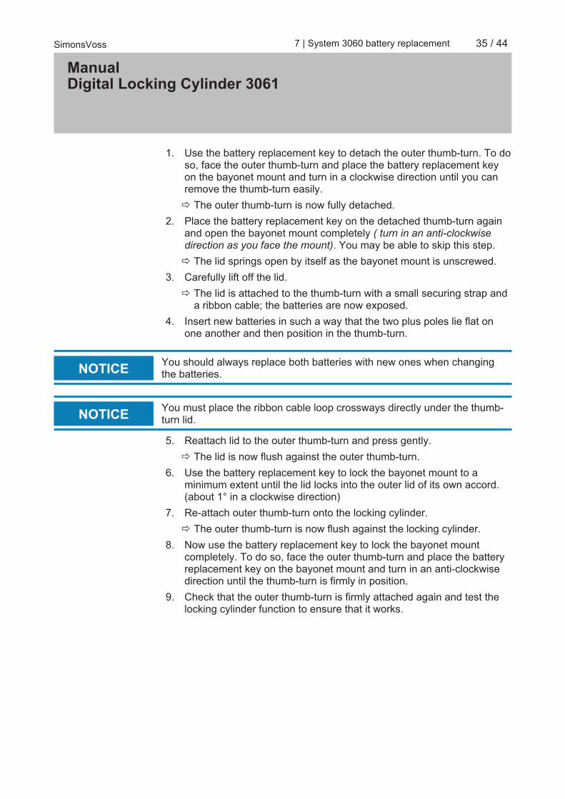
1. Use the battery replacement key to detach the outer thumb-turn. To doso, face the outer thumb-turn and place the battery replacement keyon the bayonet mount and turn in a clockwise direction until you canremove the thumb-turn easily.ð The outer thumb-turn is now fully detached.
2. Place the battery replacement key on the detached thumb-turn againand open the bayonet mount completely ( turn in an anti-clockwisedirection as you face the mount). You may be able to skip this step.ð The lid springs open by itself as the bayonet mount is unscrewed.
3. Carefully lift off the lid.ð The lid is attached to the thumb-turn with a small securing strap and
a ribbon cable; the batteries are now exposed.4. Insert new batteries in such a way that the two plus poles lie flat on
one another and then position in the thumb-turn.
NOTICE You should always replace both batteries with new ones when changingthe batteries.
NOTICE You must place the ribbon cable loop crossways directly under the thumb-turn lid.
5. Reattach lid to the outer thumb-turn and press gently.ð The lid is now flush against the outer thumb-turn.
6. Use the battery replacement key to lock the bayonet mount to aminimum extent until the lid locks into the outer lid of its own accord.(about 1° in a clockwise direction)
7. Re-attach outer thumb-turn onto the locking cylinder.ð The outer thumb-turn is now flush against the locking cylinder.
8. Now use the battery replacement key to lock the bayonet mountcompletely. To do so, face the outer thumb-turn and place the batteryreplacement key on the bayonet mount and turn in an anti-clockwisedirection until the thumb-turn is firmly in position.
9. Check that the outer thumb-turn is firmly attached again and test thelocking cylinder function to ensure that it works.
ManualDigital Locking Cylinder 3061
36 / 44SimonsVoss 8 | Maintenance, cleaning and disinfection
8 Maintenance, cleaning and disinfection
NOTICE Digital locking cylinders MUST not come into contact with oil, grease, paintor acids.
NOTICE The use of unsuitable or aggressive disinfectants can damage the lockingcylinder.Clean the locking cylinder if necessary with a soft, moist cloth.Only use disinfectants explicitly suitable for the disinfection of sensitivemetal surfaces and plastic.
NOTICE HZ.SL:it is recommended to grease the latching edge on the electrical en-closure lever handle.
Empty batteries always must be replaced by new ones approved for use bySimonsVoss. Dispose of old batteries in the proper manner.Carry out a new functional test after changing the batteries in anti-paniccylinders.

ManualDigital Locking Cylinder 3061
37 / 44SimonsVoss 9 | Areas of use
9 Areas of use
9.1 GeneralThe digital locking cylinder is compatible with locks for Euro profile cylinderas per DIN 18252 and EN1303.
9.2 Fire doorsAs a general rule, this cylinder can be fitted into fire doors. However, youmust check that it is actually approved for use in fire doors.
9.3 Doors along rescue routesType .AP should be installed for use in doors with an anti-panic function inwhich the position of the cam may have an effect on the lock's functioning.This must be specified in the lock manufacturer's approval. Also seeindustrial standards EN 179 and EN 1125 and the individual lockmanufacturers' data sheets.
9.4 Installation outdoorsIf you are unable to ensure that no water will come through the door, werecommend using the respective .WP versions. The outer thumb-turn iscompletely sealed in the anti-panic cylinder model and the whole cylinder issealed in the double thumb-turn cylinder variant.

ManualDigital Locking Cylinder 3061
38 / 44SimonsVoss 10 | Accessories
10 Accessories
10.1 Thumb-turnsThe following special thumb-turns are available as accessories:– Outer thumb-turn in a TN4 design– Outer thumb-turn, 42 mm in diameter with recessed grips– Inside thumb-turn, 36 mm in diameter for a .TS cylinder– Outer thumb-turn, shortened– Brass thumb-turn, matt (inside and outer thumb-turn)
These thumb-turns can replace the original locking cylinder thumb-turns atany time. See Installation instructions or Battery replacement for thumb-turninstallation.
10.2 Core extraction protection adapter (Z4.KA.SET)This adapter is compatible with all SKG/VdS cylinders manufactured up to2010 and all .FD cylinders.There is a mechanical extension for core extraction protection fittings as theprofile cylinder profile is not cut out of these fittings. The extension is 8 mmlong and can be retrofitted at any time.
10.3 Core extraction protection extension for SKG/VdS cylinders(Z4.KA.SET2)This adapter is compatible with all SKG/VdS cylinders manufactured in2011 and onwards.There is a mechanical extension for core extraction protection fittings as theprofile cylinder profile is not cut out of these fittings. The extension is 8 mmlong and can be retrofitted at any time.
10.4 Core extraction protection extension for SKG/VdS cylinders(Z4.KA.SET2.IT)This adapter is compatible with all SKG/VdS cylinders manufactured in2011 and onwards.There is a mechanical extension for core extraction protection fittings as theprofile cylinder profile is not cut out of these fittings. The extension length is16 mm for special Italian escutcheons and can be retrofitted at any time.
10.5 ToolIn addition to the installation tool, a battery replacement key is also includedin the supply package. You can use this tool to install or remove outerthumb-turns and replace batteries.

ManualDigital Locking Cylinder 3061
39 / 44SimonsVoss 10 | Accessories
10.6 Battery setA new set of batteries can be ordered, which contains ten CR2450batteries. Only ever use batteries approved by SimonsVoss.

ManualDigital Locking Cylinder 3061
40 / 44SimonsVoss 11 | Data sheets
11 Data sheets
11.1 Locking cylinderProfile cylinder Basic length: Outside 30 mm, internal 30 mm
(AP/WP 35mm)
Installation lengths in 5 mm increments, overall length up to 140 mm(max. 90 mm on one side); special lengths on request.
Batteries Type: CR, 2450, 3 VManufacturer: Sony, Panasonic, VartaQuantity: 2 units
Battery life: up to 300,000 lock operations orup to 10 years on standby
Ambient conditions Operating temperature: -25°C to +65°CStorage temperature: -35°C to +65°C
Protection class:Standard protection rating IP54(when installed); .WP variant:IP66
Air humidity: <95%: non-condensing
Features – 3,000 access events can be logged (ZK)– Network-ready with integrated LockNode (WN)– LockNode can be retrofitted– Time zone groups: G1: 5 / G2: 100– Max. number of transponders per G1 Cylinder: 8000 / G2: 64,000– Different permanent/open modes
Thumb-turns Material: Stainless steelColours: Stainless steel, brushedDiameter: 30 mm
Length: 37 mm (from front surface ofprofile)
FH cylinder thumb-turns Material:
Inside thumb-turn: stainless steelcover; recessed grip: plastic;outer thumb-turn: identical tostandard cylinders
Colours:
Cover: brushed stainless steel;recessed grip: black; outsidethumb-turn identical to standardcylinders
Diameter: 30 mm

ManualDigital Locking Cylinder 3061
41 / 44SimonsVoss 11 | Data sheets
Length: 37 mm (from front surface ofprofile)
AP cylinder thumb-turns Material: Outside thumb-turn: identical to
standard cylinders: Aluminium
Colours:Outside thumb-turn: Brushedstainless steel; internal thumb-turn: Nickel-coated aluminium
Diameter: 30 mm
Length:
Outside: 37 mm (from frontsurface of profile); internal: about36 mm (from front surface ofprofile)
MS cylinder thumb-turns Material:
Outside thumb-turn: identical tostandard cylinders; internalthumb-turn: identical to standardcylinders
Colours:
Outside thumb-turn: Cover madeof high-gloss brass; recessedgrip: matt brass: internal thumb-turn: Cover made of high-glossbrass; recessed grip: Matt brass
Diameter: 30 mm
Length: Outside: 37 mm (from frontsurface of profile)
11.2 Half cylinderThumb-turns Material: Stainless steel
Colours: Stainless steel, brushedDiameter: 30 mm
Length: 37 mm (from front surface ofprofile)
Profile cylinder Basic length: outside 30 mm, internal 10 mm
Installation lengths in 5 mm increments (no installation kit) an overalllength of up to 100 mm with a maximum length of 90 mm on the outerside of the cylinder. Greater lengths on request.
Batteries Type: CR, 2450, 3 VManufacturer: Sony, Panasonic, VartaQuantity: 2 units
Battery life: up to 300,000 lock operations orup to 10 years on standby

ManualDigital Locking Cylinder 3061
42 / 44SimonsVoss 11 | Data sheets
Features – 3,000 access events can be logged (ZK)– Network-ready with integrated LockNode (WN)– LockNode can be retrofitted– Time zone groups: G1: 5 / G2: 100– Max. number of transponders per G1 Cylinder: 8000 / G2: 64,000– Different permanent/open modes
Ambient conditions Operating temperature: -25°C to +65°CStorage temperature: -35°C to +65°C
Protection class:Standard protection rating IP54(when installed); .WP variant:IP66 thumb-turn
Air humidity: <95%: non-condensing
Cam HZ.SL Cam position handle: 37°Cam width from neutral position: 11 mm

ManualDigital Locking Cylinder 3061
43 / 44SimonsVoss 12 | Declaration of conformity
12 Declaration of conformityYou can access documents such as declarations of conformity and othercertificates online at www.simons-voss.com.

ManualDigital Locking Cylinder 3061
44 / 44SimonsVoss 13 | Help & Contact
13 Help & ContactInstruction manuals You will find detailed information on operation and configuration
online under INFOCENTER > DOWNLOADS on our homepage at www.simons-voss.de
Hotline If you have any questions, the SimonsVoss Service Hotline will behappy to help you on +49 (0)89 99 228 333 (German fixed network;call charges vary, depending on the operator)
Email You may prefer to send us an [email protected]
FAQs You will find information and help for SimonsVoss products in theFAQs section under INFO CENTRE > FAQ SECTION at www.simons-voss.de
SimonsVoss Technologies GmbH, Feringastrasse 4, 85774Unterföhring, Germany