manualencoders with profibus interface
TRANSCRIPT

Manual
R67068.0002 - 2
Encoders with PROFIBUS interface
Table of Contents Kübler Group
2 - EN HB Profibus Interface - R67068.0002 - 02
Table of Contents1 Document ........................................................................................................................ 4
2 General Information........................................................................................................ 52.1 Target Group........................................................................................................... 52.2 Symbols used / Warnings and Safety instructions.................................................. 5
3 Product Description ....................................................................................................... 73.1 Technical Data Sendix 58xx ................................................................................... 73.2 Technical Data Sendix 70xx ................................................................................... 83.3 PROFIBUS Interface Description............................................................................ 93.4 Supported Standards and Protocols ....................................................................... 10
4 Installation....................................................................................................................... 114.1 Electrical Installation ............................................................................................... 11
4.1.1 General Information for the Connection.................................................... 114.1.2 Terminal Assignment 58xx........................................................................ 114.1.3 Terminal Assignment 70xx........................................................................ 134.1.4 Termination ............................................................................................... 144.1.5 Network Topology ..................................................................................... 15
5 Commissioning and Operation ..................................................................................... 165.1 Function and Status LED ........................................................................................ 165.2 Quick Start Guide.................................................................................................... 17
5.2.1 Default Settings......................................................................................... 175.2.2 Configuring the Modules ........................................................................... 19
5.3 Protocol Features.................................................................................................... 225.3.1 Device Profile V1.1.................................................................................... 225.3.2 The Requirements Profile ......................................................................... 225.3.3 Slave Mode ............................................................................................... 235.3.4 Encoder Start-up Phase on the PROFIBUS ............................................. 235.3.5 Configuration and Parameterizing ............................................................ 235.3.6 Protective Functions.................................................................................. 23
5.4 Configuration Parameters Description .................................................................... 245.4.1 Modules..................................................................................................... 245.4.2 Speed........................................................................................................ 285.4.3 Station Address......................................................................................... 295.4.4 Scaling ...................................................................................................... 305.4.5 Preset........................................................................................................ 31
5.5 Examples ................................................................................................................ 325.5.1 Changing the Station Address with SSA................................................... 325.5.2 Performing a Preset .................................................................................. 34
6 Annex............................................................................................................................... 366.1 Extended Diagnostic ............................................................................................... 366.2 Service Access Point (SAP).................................................................................... 37

Kübler Group Table of Contents
HB Profibus Interface - R67068.0002 - 02 EN - 3
6.3 Decimal / Hexadecimal conversion table ................................................................ 38
7 Contact ............................................................................................................................ 40
Glossary .......................................................................................................................... 41
1 Document Kübler Group
4 - EN HB Profibus Interface - R67068.0002 - 02
1 DocumentThis document is the English translation of the original German version.
Publisher Kübler Group, Fritz Kübler GmbHSchubertstraße 4778054 Villingen-SchwenningenGermanywww.kuebler.com
Issue date 09/2020Language version German is the original languageCopyright © 2020, Kübler Group, Fritz Kübler GmbHImage sources Siemens - TIA Portal v14
Bihl + Wiedemann – PROFIBUS Master Simulator
Legal noticesAll of the contents of this document are protected by the rights of use and copyrights of FritzKübler GmbH. Any duplication, modification, further use and publications in other electronic orprinted media, as well as their publication in the Internet, even partially, is subject to the previ-ous written authorization of Fritz Kübler GmbH.The brand names and product brands mentioned in this document are trademarks or registeredtrademarks of the respective titleholders.Subject to errors and changes. The stated product features and technical data shall not consti-tute any guarantee declaration.

Kübler Group 2 General Information
HB Profibus Interface - R67068.0002 - 02 EN - 5
2 General InformationPlease read this document carefully before working with the product, mounting itor starting it up.
2.1 Target GroupThe device may only be planned, mounted, commissioned and serviced by persons having thefollowing qualifications and fulfilling the following conditions:• Technical training.• Briefing in the relevant safety guidelines.• Constant access to this documentation.• In case of electrical equipment for potentially explosive atmospheres, the specialized person-
nel needs knowledge about the ignition protection category concept.• For facilities in potentially explosive atmospheres, the authorized person must comply with
the applicable country-specific regulations.
2.2 Symbols used / Warnings and Safety instructions DANGER Classification:
This symbol, together with the signal word DANGER, warns againstimmediately imminent threat to life and health of persons.
The non-compliance with this safety instruction will lead to death orsevere adverse health effects.
WARNING Classification:
This symbol, together with the signal word WARNING, warns againsta potential danger to life and health of persons.
The non-compliance with this safety instruction may lead to death orsevere adverse health effects.
CAUTION Classification:
This symbol, together with the signal word CAUTION, warns againsta potential danger for the health of persons.
The non-compliance with this safety instruction may lead to slight orminor adverse health effects.
ATTENTION Classification:
The non-compliance with the ATTENTION note may lead to materialdamage.

2 General Information Kübler Group
6 - EN HB Profibus Interface - R67068.0002 - 02
NOTICE Classification:
Additional information relating to the operation of the product, andhints and recommendations for efficient and trouble-free operation.

Kübler Group 3 Product Description
HB Profibus Interface - R67068.0002 - 02 EN - 7
3 Product Description
3.1 Technical Data Sendix 58xxSingleturn technology OpticalMultiturn technology Optical, mechanical gearSingleturn resolution (MUR) Max. 16 bits (default 13 bits)Multiturn resolution (NDR) Max. 12 bitsMultiturn resolution (TMR) Max. 28 bits (default 25 bits)Accuracy ± 0.0117° (over the whole
temperature range)Data up-to-dateness 5 ms
Mechanical characteristics for the Sendix 58xx encoders
Maximum rotary speed IP65 up to 70°C
IP65 up to Tmax
IP67 up to 70°C
IP67 up to Tmax
9000 min-1, 7000 min-1 (continuous operation) 7000 min-1, 4000 min-1 (continuous operation)8000 min-1, 6000 min-1 (continuous operation) 6000 min-1, 3000 min-1 (continuous operation)
Starting torque (at 20°C) IP65 IP67
< 0.01 Nm< 0.05 Nm
Mass moment of inertia Shaft version Hollow shaft version
3,0 x 10⁻⁶ kgm2
7,5 x 10⁻⁶ kgm2 (MT)6 x 10⁻⁶ kgm2 (ST)
Permissible shaft load radial axial
80 N40 N
Protection level acc. to EN 60529 Housing side Shaft side
IP67IP65, optional IP67
Working temperature range -40°C ... +80°CMaterials Shaft/hollow shaft Flange Housing
Stainless steelAluminumDie-cast zinc
Shock resistance according to EN 60068-2-27 2500 m/s2, 6 msVibration resistance according toEN 60068-2-6
100 m/s2, 55 ... 2000 Hz

3 Product Description Kübler Group
8 - EN HB Profibus Interface - R67068.0002 - 02
Electrical data for the Sendix 58xx encoders
Supply voltage 10 … 30 V DCCurrent consumption (no load) 10 … 30 V DC max. 110 mASupply voltage reverse polarity protection Yes
Interface PROFIBUS PROFIBUS DP V0Encoder profile Class 2Encoder profile 3062 V1.1
Resolution Singleturn (MUR) Multiturn (NDR) Total resolution (TMR)
Max. 28 bits (default 25 bits)Max. 12 bits Max. 28 bits (default 25 bits)
Type of connection 3 x M12 connector
3.2 Technical Data Sendix 70xxSingleturn technology OpticalMultiturn technology Optical, mechanical gearSingleturn resolution (MUR) Max. 16 bits (default 13 bits)Multiturn resolution (NDR) Max. 12 bitsMultiturn resolution (TMR) Max. 28 bits (default 25 bits)Accuracy ± 0.0117° (over the whole
temperature range)Data up-to-dateness 5 ms
Mechanical data for Sendix 70xx
Maximum rotational speed 6000 min-1
Maximum angular acceleration 5x10⁵ rad/s²Operating/storage andtransport temperature range
-40°C ... +60°C [-40°F … 140°F]
Protection level according to EN 60529 IP67Protection level according to NEMA 250 Type 6Installation height < 2000 m [6562 ft]Shock resistance according to EN / IEC 60068-2-27 500 m/s2, 11 msVibration resistance according to EN / IEC 60068-2-6 5 ... 2000 Hz, 200 m/s2

Kübler Group 3 Product Description
HB Profibus Interface - R67068.0002 - 02 EN - 9
Electrical data for the Sendix 70xx encoders
Supply voltage(depending on the variant)
5 V DC5 … 30 V DC10 … 30 V DC
Current consumption (no load) 5 V DC 5 … 30 V DC 10 … 30 V DC
max. 90 mAmax. 100 mAmax. 100 mA
Protection class according to EN 61140 III (PELV)
EMC - Electromagnetic Compatibility
Relevant Standards EN 55011 Class B:2009 / A1:2010EN 61326-1:2013
Kübler tested the conformity of the system on a typical construction with a motor size 80.System responsibility lies with the motor/system manufacturer.
Interface PROFIBUS PROFIBUS DP V0Encoder profile Class 2Encoder profile 3062 V1.1
Resolution Singleturn (MUR) Multiturn (NDR) Total resolution (TMR)
Max. 16 bits (default 13 bits)Max. 12 bitsMax. 28 bits (default 25 bits)
Type of connection 3 x M12 connector
3.3 PROFIBUS Interface DescriptionThe main task of PROFIBUS DP is the cyclic transmission of process data from the control sys-tem to the peripheral devices and vice versa. The access procedure uses the master-slave prin-ciple. In polling operation, the master serves the slave devices assigned to it one after the other.Data exchange is initiated by a query telegram and ended by an acknowledgment telegramfrom the addressed slave. Thus every slave becomes active only upon request from the master.This prevents simultaneous bus access. The hybrid access method of PROFIBUS allows com-bined operation of several bus masters or mixed operation of PROFIBUS DP andPROFIBUS FMS within a bus section.Prerequisite for this is, however, the proper configuration of the bus system and the unambigu-ous allocation of the slave devices to the masters. PROFIBUS DP distinguishes two mastertypes:Class 1 master (DPM1): generally the automation system (PLC). It is in charge of the cyclictransmission of the operating data and makes the user data available. The Class 1 master canbe addressed by a class 2 master that uses determined functions such as e. g. read or writeservices via an initiate service.Class 2 master (DPM2): the engineering tool that exclusively performs acyclic data transmis-sion. The communication on the bus is based on whether a class 1 master or a class 2 masterinitiates the communication.

3 Product Description Kübler Group
10 - EN HB Profibus Interface - R67068.0002 - 02
NOTICE Direct access to the slaves is not allowed.
The functions are limited to slave support services such as e.g. thereadout of diagnostic information. Therefore, a class 2 master is un-derstood as a programming or diagnostic device.
3.4 Supported Standards and ProtocolsClass 1Resolution 16 bits(typ. singleturn)
Class 2Resolution 32 bits(typ. multiturn)
In/output consistent The encoder uses1 input word and1 output word, which arerespectively consistently trans-mitted via the bus.
The encoder uses2 input words and2 output words, which are re-spectively consistently transmit-ted via the bus.
Input consistent The encoder uses1 input word, which is consist-ently transmitted via the bus.
The encoder uses2 input words, which are respect-ively consistently transmitted viathe bus.
For commissioning, the device requires the corresponding GSD data:
Version Series GSD fileSingleturn 5858 KUEB5868ST.gsd
5878 KUEB5868ST.gsd7058 KUEB7058.gsd7078 KUEB7058.gsd7158 KUEB7158.gsd7178 KUEB7158.gsd
Multiturn 5868 KUEB5868.gsd5888 KUEB5868.gsd7068 KUEB7068.gsd7088 KUEB7068.gsd7168 KUEB7168.gsd7188 KUEB7168.gsd

Kübler Group 4 Installation
HB Profibus Interface - R67068.0002 - 02 EN - 11
4 Installation
4.1 Electrical Installation
4.1.1 General Information for the Connection
ATTENTION Destruction of the device
Before connecting or disconnecting the signal cable, always discon-nect the power supply and secure it against switching on again.
NOTICE General safety instructions
Make sure that the whole plant remains switched off during the elec-trical installation.
• Make sure that the operating voltage is switched on or off simultan-eously for the device and the downstream device.
NOTICE Traction relief
Always mount all cables with traction relief.
NOTICE Interference susceptibility
Proceed as follows:
• Connect the shield to the device housing.• Comply with the maximum cable length for stub lines and for the
total length of the bus network.• Check the maximum supply voltage on the device.
ATTENTION Wear of the memory module
Avoid too frequent writing of the EEPROM. It is used e.g. when set-ting a preset value. The memory module is designed for approxim-ately 500,000 write cycles. If the maximum number of write cycles isexceeded, single memory areas may be damaged and errors mayoccur.
4.1.2 Terminal Assignment 58xxPROFIBUS connection M12 connector
4 Installation Kübler Group
12 - EN HB Profibus Interface - R67068.0002 - 02
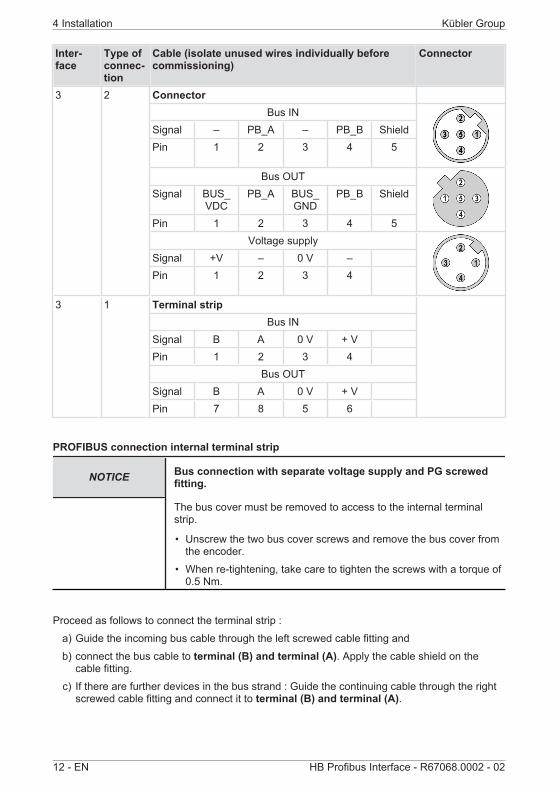
Inter-face
Type ofconnec-tion
Cable (isolate unused wires individually beforecommissioning)
Connector
3 2 ConnectorBus IN
Signal – PB_A – PB_B ShieldPin 1 2 3 4 5
Bus OUTSignal BUS_
VDCPB_A BUS_
GNDPB_B Shield
Pin 1 2 3 4 5Voltage supply
Signal +V – 0 V –Pin 1 2 3 4
3 1 Terminal stripBus IN
Signal B A 0 V + VPin 1 2 3 4
Bus OUTSignal B A 0 V + VPin 7 8 5 6
PROFIBUS connection internal terminal strip
NOTICE Bus connection with separate voltage supply and PG screwedfitting.
The bus cover must be removed to access to the internal terminalstrip.
• Unscrew the two bus cover screws and remove the bus cover fromthe encoder.
• When re-tightening, take care to tighten the screws with a torque of0.5 Nm.
Proceed as follows to connect the terminal strip :a) Guide the incoming bus cable through the left screwed cable fitting andb) connect the bus cable to terminal (B) and terminal (A). Apply the cable shield on the
cable fitting.c) If there are further devices in the bus strand : Guide the continuing cable through the right
screwed cable fitting and connect it to terminal (B) and terminal (A).

Kübler Group 4 Installation
HB Profibus Interface - R67068.0002 - 02 EN - 13
Supply voltagea) Guide the encoder supply voltage through the central screwed cable fitting and connect it
to the left terminals (+V) and terminal (0 V).b) Apply the cable shield on the cable fitting.
103389963
NOTICE Duplicated signals
All signal inputs/outputs are duplicated and connected internally.
Abbreviation Designation DirectionB Profibus OutA Profibus Out0V 0 volt supply Out+V +UB supply Out0V 0 volt supply In+V +UB supply InB Profibus InA Profibus In
4.1.3 Terminal Assignment 70xxCableSignal 0 V +V PB_A
INPB_B
INBUS_GND
BUS_VDC
PB_AOUT
PB_BOUT
Wire la-beling
1 2 4 5 6 7 8 9 Shield
4 Installation Kübler Group
14 - EN HB Profibus Interface - R67068.0002 - 02
4.1.4 TerminationIf a device is the last participant on the bus, the looped-through PROFIBUS must be terminatedactively at both ends with a bus termination resistor between A and B. For closed devices, thetermination must be specified in the order or provided by means of en external resistor. Forgood signal transmission, PROFIBUS segments must be terminated with a bus termination. ForPROFIBUS RS485, the bus termination consists of three resistors.The bus termination can be activated in the device or is prepared in the switch. If more than 32participants are connected to the bus, repeaters must be used to connect the single bus seg-ments. The terminating resistors between the lines are generally 220 Ω. 390 Ω resistors areused between the reference potentials. Generally, the line termination is located in the cables orin the respective PROFIBUS device, but it can also be installed separately. Network Topology[ 15]Cable terminationEvery bus segment must be terminated at both ends with a termination resistor. This cable ter-mination is integrated in the RS485 repeaters, in the bus terminals and in the bus connectors,and it can, if necessary, be activated. The component must be powered before the cable termin-ation can be activated. The RS485 repeaters and the termination have their own power supply.The RS485 transmission technology allows connecting at the maximum 32 devices per bussegment (DTE's and Repeaters).The maximum permissible cable length depends on the transmission speed and on the usedLAN cable. Network Topology [ 15]
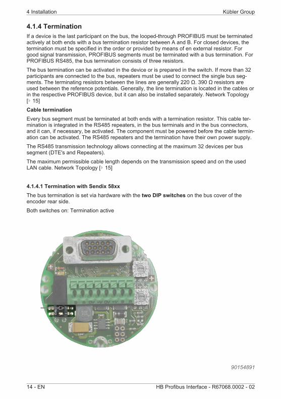
4.1.4.1 Termination with Sendix 58xxThe bus termination is set via hardware with the two DIP switches on the bus cover of theencoder rear side.Both switches on: Termination active
90154891
Kübler Group 4 Installation
HB Profibus Interface - R67068.0002 - 02 EN - 15
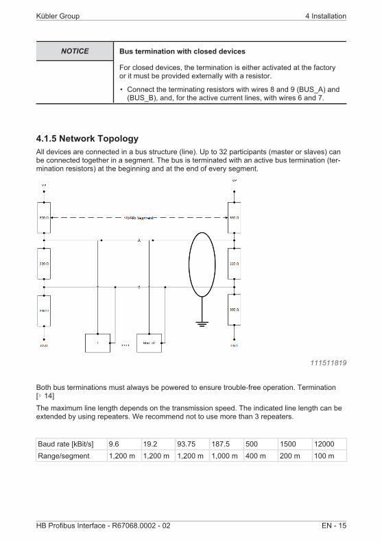
NOTICE Bus termination with closed devices
For closed devices, the termination is either activated at the factoryor it must be provided externally with a resistor.
• Connect the terminating resistors with wires 8 and 9 (BUS_A) and(BUS_B), and, for the active current lines, with wires 6 and 7.
4.1.5 Network TopologyAll devices are connected in a bus structure (line). Up to 32 participants (master or slaves) canbe connected together in a segment. The bus is terminated with an active bus termination (ter-mination resistors) at the beginning and at the end of every segment.
111511819
Both bus terminations must always be powered to ensure trouble-free operation. Termination[ 14]The maximum line length depends on the transmission speed. The indicated line length can beextended by using repeaters. We recommend not to use more than 3 repeaters.
Baud rate [kBit/s] 9.6 19.2 93.75 187.5 500 1500 12000Range/segment 1,200 m 1,200 m 1,200 m 1,000 m 400 m 200 m 100 m

5 Commissioning and Operation Kübler Group
16 - EN HB Profibus Interface - R67068.0002 - 02
5 Commissioning and Operation
5.1 Function and Status LED• Red LED = DIAG• Yellow LED = BUS• Green LED = PWR
Display LED Meaning Error cause AdditionPWR off No bus voltage present No voltage on
the devicePower supply defective
Check the voltagesupply
PWR on Bus voltagepresentDevice ready for oper-ation
Device in configurationmode
BUS off
Device waiting for con-figuration or paramet-erizing
GSD module must beloaded and sent to theencode
Observe the combin-ation with the DIAGLED.
BUS on Connection to themaster establishedDATA_Exchangemode
Process dataexchange
LED combinations during operation
Display LED Meaning Error cause AdditionPWR+BUS on
DATA_Exchangemode
Device ready for pos-ition dataexchange
Diagflashing
Red LED flashing Temperature overrunSensor monitoringSingle-step errorSensor LED currentmonitoring
Connection to themasterwhen connecting+ additional errorcause(Diagnostic headerrequested)

Kübler Group 5 Commissioning and Operation
HB Profibus Interface - R67068.0002 - 02 EN - 17
Error display after powering
Display LED Meaning Error cause AdditionPWR+Diagflashing
Red LED flashing1 x brieflyPause 1.6 sec.
Data connection withsensor faultySensor faulty
Device must be sentback to manufacturerfor check
PWR+Diagflashing
Red LED flashing2 x brieflyPause 1.6 sec.
Wrongnode addressProfibus short-circuitTermination faulty
Check Profibus
General RESET - Switching the device on while pressing the SET key
Display LED Meaning Error cause AdditionPWR+Diagflashing
Short flashing ofthe red LED
Diagnostic mode Device ready for dia-gnostic
5.2 Quick Start Guide
5.2.1 Default SettingsBefore a PROFIBUS DP system can be started up, all connected participants, including themaster system, must be assigned unique bus addresses. Only this way will an unambiguousaddressing be ensured on the bus. The addresses of the stations must first be assigned via thebus.The physical system settings then follow through the parameters set of the master. Besides themaster bus address, this set includes e. g. the baud rate, the timeout times and the number oftransmission repetitions. In addition to the master parameters set, a slave parameters set mustbe saved for every slave to be activated. A data set contains the parameter assignment andconfiguration data of the slave and the address pointer for the logical storage of the I/O data.When the parameter sets are present, the master system begins to start up the slaves one afterthe other, either upon user request or automatically.The first so-called diagnostic cycles show which slave is present on the bus. Only the slavesthat send a proper feedback during the diagnostic cycle are subsequently parameterized duringthe parameterizing cycles with the corresponding data stored in the master. After error-free exe-cution, the configuration cycles compare the required configuration stored in the master with theactual configuration of the slaves. After the last diagnostic cycle, every slave that did not detectany error during the comparison is ready for operation.Each of these slaves is automatically integrated by the master in the operating data exchange.For diagnostic purposes, the master provides a diagnostic buffer for every slave. This buffer canbe read out by the user for other purposes. To make diagnostic easier, a group diagnostic fieldis kept simultaneously. This field shows bit by bit whether it holds diagnostic data for a slave ornot.The following parameters are factory-set:
5 Commissioning and Operation Kübler Group
18 - EN HB Profibus Interface - R67068.0002 - 02
Designation Default Switch ProductBaud rate Automatic Not availableNode address 63 – without SSA Switch setting 0x3F Sendix 58xx
125 - with SSA For devices without removable buscover setting 0xFF (node address viasoftware changeSee Set Slave Address (SSA) [ 30].
Sendix 70xx
Termination Off Switch setting off Sendix 58xx
Name Default Byte BitCode sequence 0 = CW 9 0Class 2 functionality 1 = Class 2 on 9 1Scaling 1 = Scaling on 9 3Scaling type 0 = standard (MUR + TMR) 9 7Scaling parameter MUR MUR = 8192 (13 bits) 10 … 13 0 … 7Scaling parameter TMR TMR = 33554432 (25 bits) 14 … 17 0 … 7
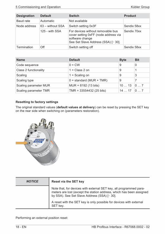
Resetting to factory settingsThe original standard values (default values at delivery) can be reset by pressing the SET keyon the rear side when switching on (parameters restoration).
NOTICE Reset via the SET key
Note that, for devices with external SET key, all programmed para-meters are lost (except the station address, which has been assignedby SSA). See Set Slave Address (SSA) [ 30].
A reset with the SET key is only possible for devices with externalSET key.
Performing an external position reset:

Kübler Group 5 Commissioning and Operation
HB Profibus Interface - R67068.0002 - 02 EN - 19
a) Switch the encoder off.b) When switching it back on, hold the SET key pressed for about 3 seconds, until the DIAG
LED flashes.c) Switch the device off again.ð When switching it on again, all values will be reset to the default settings.
If errors occurred during the programming of the objects, and if these parameters are saved inthe EPROM, addressing the encoder will not be possible when switching it on the next time.This error can only be corrected by a general Reset of the encoder.
Also refer to2 Extended Diagnostic [ 36]
5.2.2 Configuring the ModulesTo be able to perform a general parameterizing of the device, the corresponding GSD file mustbe selected and implemented first (e. g. KUEB7068.GSD). It can be found on the Kübler webpage of the concerned product.The respective software allows including the GSD files.
Then a Module of the GSD file must be selected for the configuration.

5 Commissioning and Operation Kübler Group
20 - EN HB Profibus Interface - R67068.0002 - 02
8 different modules are available :• Universal module• 32-bit input/output, consistent• 32-bit input, consistent• 16-bit input/output, consistent• 16-bit input, consistent• MUR = 13 bits and TMR = 25 bits (input/output, consistent)• Rotational speed (RPM) 16 bits• Speed (units/s) 32 bitsThe modules describe the structure of the input and output data. Input data is data sent by theencoder. Output data is sent from the control to the encoder. At the maximum 2 modules can beused simultaneously.
The following input words can be combined:• Resolution 32 bits, input consistent + Resolution 16 bits Speed in (units/s)• Resolution 16 bits, input consistent + Resolution 32 bits Rotational speed in (rpm)
The modules (except for the 25-bit configuration) allow defining the following :
• Code sequence (byte 9, bit 0)0 = clockwise1 = counter-clockwise
• Class 2 functionality (byte 9, bit 1)0 = no1 = yes
Kübler Group 5 Commissioning and Operation
HB Profibus Interface - R67068.0002 - 02 EN - 21
• Scaling release (byte 9, bit 3)0 = no1 = yes
• Scaling type (byte 9, bit 7)0 = standard (MUR + TMR)1 = alternative (NDR + TMR)
• Scaling parameter MUR or NDR (bytes 10-13)MUR = Measuring Units per RevolutionNDR = Number of Distinguished Revolutions
• Scaling parameter TMR (bytes 14-17)TMR = Total Measuring Range
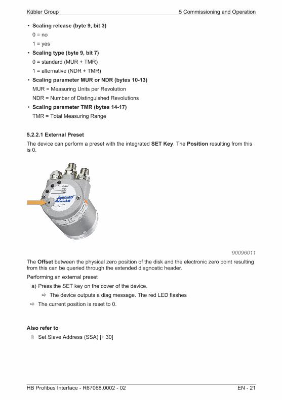
5.2.2.1 External PresetThe device can perform a preset with the integrated SET Key. The Position resulting from thisis 0.
90096011
The Offset between the physical zero position of the disk and the electronic zero point resultingfrom this can be queried through the extended diagnostic header.Performing an external preset
a) Press the SET key on the cover of the device.ð The device outputs a diag message. The red LED flashes
ð The current position is reset to 0.
Also refer to2 Set Slave Address (SSA) [ 30]

5 Commissioning and Operation Kübler Group
22 - EN HB Profibus Interface - R67068.0002 - 02
5.3 Protocol Features
5.3.1 Device Profile V1.1This profile describes a manufacturer-independent and binding specification of the interface forencoders. The protocol defines which Profibus functions are used and how they are used. Thisstandard allows for an open and manufacturer-independent bus system.The device profile is subdivided in two object classes:
Class C1
Class C2
Class C2
Physical position
Basic function
Absolute position
Scaling function
Preset function
Output position value
114716171
• Class C1 describes all basic functions the encoder is to offer.• Class C2 includes a wide range of extended functions, which have to be supported by the
encoders of this class (mandatory) or which are optional. So devices of class C2 include allC1 and mandatory C2 functions, as well as further manufacturer-specific optional functions.Moreover, an address range, which can receive manufacturer-specific special functions, isdefined in the profile.
5.3.2 The Requirements ProfileThe connection between the decentralized process flow and the central control through thecommunication system takes place at the lowest hierarchical level via the field or process bus.At this level, the main requirements are a simple protocol procedure and short data transmis-sion times for the communication.This ensures the shortest system response time possible to the dynamic states of the peripheraldevices. Besides the classical data exchange, the acyclic transmission of parameter, diagnosticand configuration data must be possible too without fundamentally affecting the real-time cap-ability of the bus. This is the only way to ensure a good diagnostic and safe operation.
Kübler Group 5 Commissioning and Operation
HB Profibus Interface - R67068.0002 - 02 EN - 23
5.3.3 Slave ModeThis description contains information about the implementation of the PROFIBUS DP transmis-sion protocol in the slave mode on our devices. The scope of the described functions can belimited according to the device or to the application In particular, less functions are generallyused in the event of protocol conversions.
5.3.4 Encoder Start-up Phase on the PROFIBUSWhen starting up, the encoder is in the BAUD SEARCH state. After having detected the baudrate, it switches to the WAIT_PRM state and waits for the parameterizing data from the DP mas-ter. Parameterizing takes place automatically when the DP master starts.The following parameters are transmitted to the encoder: Counting direction and measuringlength in steps (for more information, see encoder profile of PNO).After successful transmission of the correct parameterizing data the encoder switches to theWAIT_CFG state. The PROFIBUS master sends a configuration byte to determine the numberof inputs/outputs. If the configuration byte is correct, the encoder switches to the DATA_EX-CHANGE state.
5.3.5 Configuration and ParameterizingParameterizing, i. e. the transmission of the parameters for counting direction, encoder resolu-tion, etc., generally takes place within the configuration program of the used PROFIBUS master.To this purpose, the type or GSD file (device file) must be copied in the directory for the type orGSD files. With programs such as COM PROFIBUS or STEP7 Manager, an update of the in-ternal devices list (hardware catalog) must be performed in the software.For further information on the integration of field devices, refer to the documentation of the usedsoftware.Changing the station addressIf the station address needs to be changed, the master must support Class 2. This operation ispossible in the start-up phase of the device.
5.3.6 Protective FunctionsPROFIBUS DP is provided with many protective functions. They ensure safe and error-freecommunication, not only in the harsh environment of the decentralized peripheral devices, butalso in the event of external interferences or failure of one or more participants. Faulty paramet-erizing is detect directly, since participants with wrong parameters are not integrated in the op-erating data exchange.The failure of participants is recorded by the master and displayed for the user with a group dia-gnostic message. Every failure in the transmission path is detected by the slave by means oftime monitoring and leads to the switching off of the outputs.EMC interferences are almost filtered out through the differential signal of the interference-safeRS485 transmission system.Errors during data transmission are detected by frame and check sum monitoring and lead tothe repetition of the telegram.
5 Commissioning and Operation Kübler Group
24 - EN HB Profibus Interface - R67068.0002 - 02
5.4 Configuration Parameters Description
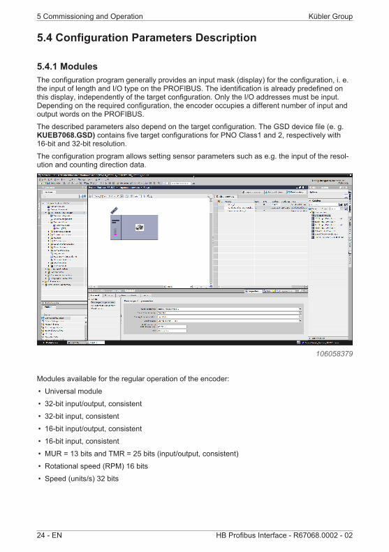
5.4.1 ModulesThe configuration program generally provides an input mask (display) for the configuration, i. e.the input of length and I/O type on the PROFIBUS. The identification is already predefined onthis display, independently of the target configuration. Only the I/O addresses must be input.Depending on the required configuration, the encoder occupies a different number of input andoutput words on the PROFIBUS.The described parameters also depend on the target configuration. The GSD device file (e. g.KUEB7068.GSD) contains five target configurations for PNO Class1 and 2, respectively with16-bit and 32-bit resolution.The configuration program allows setting sensor parameters such as e.g. the input of the resol-ution and counting direction data.
106058379
Modules available for the regular operation of the encoder:• Universal module• 32-bit input/output, consistent• 32-bit input, consistent• 16-bit input/output, consistent• 16-bit input, consistent• MUR = 13 bits and TMR = 25 bits (input/output, consistent)• Rotational speed (RPM) 16 bits• Speed (units/s) 32 bits

Kübler Group 5 Commissioning and Operation
HB Profibus Interface - R67068.0002 - 02 EN - 25
NOTICE Combination of modules
All configurations can be combined with the rotational speed (RPM)16 bits consistent or the speed (units/s) 32 bits consistent.
Various settings can be performed within the modules. They are done in the input mask of theused program.
Direction of rotation:• Increasing in clockwise direction (0) (CW)• Increasing in counter-clockwise direction (1) (CCW)
9007199360906507

5 Commissioning and Operation Kübler Group
26 - EN HB Profibus Interface - R67068.0002 - 02
Class 2 functionality onIf scaling is active, class 2 must be switched on.
9007199360908171
Scaling function control onWhen scaling is switched on – the position depends on the MUR and TMR values.
9007199360909835

Kübler Group 5 Commissioning and Operation
HB Profibus Interface - R67068.0002 - 02 EN - 27
Scaling type MUR + TMRScaling type (MUR + TMR)
9007199360911499
Value for resolution per revolution MURExample: 3600 steps per revolution
9007199360913163
Value for total resolutionExample: Value for total resolution 36000Position range: 0…36000Revolutions 10

5 Commissioning and Operation Kübler Group
28 - EN HB Profibus Interface - R67068.0002 - 02
9007199360914827
5.4.2 SpeedAll modules can be combined with the configuration of an additional speed value. The inputwords are extended, depending on the configuration of the speed value, up to a maximumlength of 8 bytes (64 bits). The speed value is signed and depends on the counting direction.Positive values clockwise, negative values counter-clockwise. Format is “Big Endian”:
Input word Input word Format Max.Byte 0 Byte 1 Byte 2 Byte 3 - -
0 0 RPM 017 70 RPM 6000E8 90 RPM -6000
00 63 FF 9C Unit/s 6553500FF 9C 00 64 Unit/s -6553500
Rotational speed limitations
NOTICE Calculation basis for the speed (steps/s).
The physical singleturn is always assumed as the calculation basis(65536 steps/revolution) when setting the speed (steps/s).
Singleturn encoders: 600 rpm higher rotational speeds produce value ffffhMultiturn encoders: 12,000 rpm higher rotational speeds produce value ffffh

Kübler Group 5 Commissioning and Operation
HB Profibus Interface - R67068.0002 - 02 EN - 29
5.4.3 Station AddressThe station address is set by means of the two address rotary switches. Default address at de-livery is 0x3F (63 dec.)
NOTICE Setting the station address (software orhardware side)
These settings have higher priority than the software setting of themaster. With devices without removable bus cover, the default settingis 0xFFh for the software.
115555851
Switch Values range Ex. for address 3F
1 Least significant address rotary switch x1Values range 1..F *
F
2 Most significant address rotary switch x10Values range 1..7 *
3
Station address 0 is reserved and shall not be used for any node. The resulting node numbersare in the range 1...7Dh hexadecimal (1... 125 decimal).
5 Commissioning and Operation Kübler Group
30 - EN HB Profibus Interface - R67068.0002 - 02
NOTICE Taking over a new station address
A new node number is only taken into consideration at the followingbooting (Reset/Power-on) of the encoder. All other settings in the ob-jects table remain retained.
Changing the station address via software (SSA):If the 2 rotary switches are in Position Fh, the node number can also be set with a Class 2master in the Profibus start sequence via the service access point SAP 55 Set_Slave_Ad-dress (SSA). Set Slave Address (SSA) [ 30]
5.4.3.1 Set Slave Address (SSA)SSA allows setting the station addresses by software. To allow this, the 2 rotary switches mustbe set to position 0xF. Default setting after booting is address 125 (0x7D). This allows settingthe node number also with a Class 2 master in the Profibus start sequence via the service ac-cess point SAP 55 Set_Slave_Address. See Service Access Point (SAP) [ 37].
NOTICE Taking over a new station address
A new station address is only taken into consideration at the followingbooting (Reset/Power-on) of the encoder. All other settings in the ob-jects table remain retained.
The station address is not reset by a reset.
Only valid addresses are saved in a non-volatile memory and be-come active.
5.4.4 ScalingStandard scaling scales as follows:• With MUR and TMR• One revolution corresponds exactly to MUR = TMR values• CW code sequence
Positionscaled = ((Positionunscaled/ Singleturn resolution) * MUR) % TMR
NOTICE Pay attention to the division factor
For the scaled total position (TMR), make sure that the programmedvalue is always an integer divisor of total resolution GP_U.
This formula shows that an exact positioning beyond the range limitsonly is possible if the division factor TMR/MUR is an integral multiple.Otherwise, position errors will occur below 0 and above the maximumrange.

Kübler Group 5 Commissioning and Operation
HB Profibus Interface - R67068.0002 - 02 EN - 31
Alternative scaling scales as follows:• With NDR and TMR• NDR revolutions correspond exactly to the TMR values• CW code sequence
Positionscaled = ((Positionunscaled/ (NDR * Singleturn resolution)) * TMR) % TMR
5.4.5 PresetIn the 'Class 2' mode, the encoder can be preset via PROFIBUS to any position value within thevalues range of 27 bits or 15 bits. This is done by setting the most significant bit (MSB) ofthe output data (4 bytes for Class 2 configuration - 32 bits or 2 bytes for Class 1 configuration -16 bits).
106050699
The preset value transmitted in data bytes 0 - 3 is taken over with the rising edge of bit 32 (= bit7 of data byte 3) as the position value. The encoder goes on counting from this position. A newsetting is only possible after the control bit has been reset. This operation id not confirmed viathe inputs.
NOTICE Warning message when performing the preset.
When performing the preset, the device issues a warning message,since the position can change suddenly by a large value. This is anintentional behavior and not an error.
5 Commissioning and Operation Kübler Group
32 - EN HB Profibus Interface - R67068.0002 - 02
5.5 Examples
5.5.1 Changing the Station Address with SSA
NOTICE Use of SSA
The use of SSA is mainly suitable for devices without removable buscover.
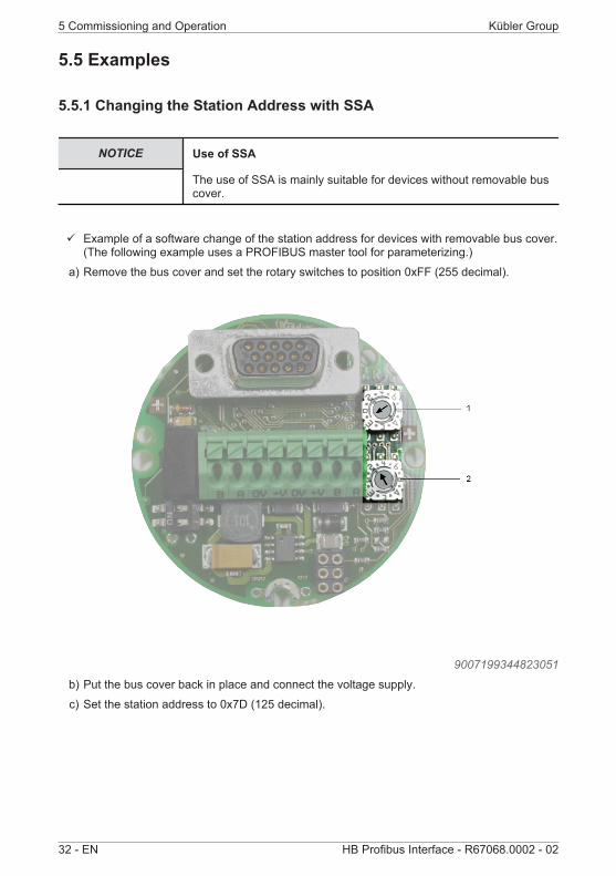
ü Example of a software change of the station address for devices with removable bus cover.(The following example uses a PROFIBUS master tool for parameterizing.)
a) Remove the bus cover and set the rotary switches to position 0xFF (255 decimal).
9007199344823051
b) Put the bus cover back in place and connect the voltage supply.c) Set the station address to 0x7D (125 decimal).

Kübler Group 5 Commissioning and Operation
HB Profibus Interface - R67068.0002 - 02 EN - 33
106363787
Writing the configuration in the control.ü Master / slave connection The device is now recognized under station address 125.
106361867
a) Disconnect the master / slave connection and change the station address to 0x0A (10decimal).
b) Write the configuration in the control.ð Mater / slave connection with new station address 10. The device is now recognized under
station address 10.

5 Commissioning and Operation Kübler Group
34 - EN HB Profibus Interface - R67068.0002 - 02
5.5.2 Performing a Presetü This example sets preset 100 decimal, which is subsequently performed.a) Enter preset value 0x64 in the output word.
106358027
b) Enter trigger bit 1 in the MSB of the output word in byte 0.c) Perform the presetð The current position value changes to 100 decimal.ð The device outputs a warning message.

Kübler Group 5 Commissioning and Operation
HB Profibus Interface - R67068.0002 - 02 EN - 35
NOTICE Warning message when performing the preset.
When performing the preset, the device issues a warning message,since the position can change suddenly by a large value. This is anintentional behavior and not an error.
6 Annex Kübler Group
36 - EN HB Profibus Interface - R67068.0002 - 02
6 Annex
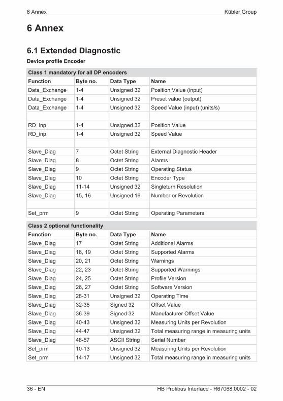
6.1 Extended DiagnosticDevice profile Encoder
Class 1 mandatory for all DP encodersFunction Byte no. Data Type NameData_Exchange 1-4 Unsigned 32 Position Value (input)Data_Exchange 1-4 Unsigned 32 Preset value (output)Data_Exchange 1-4 Unsigned 32 Speed Value (input) (units/s)
RD_inp 1-4 Unsigned 32 Position ValueRD_inp 1-4 Unsigned 32 Speed Value
Slave_Diag 7 Octet String External Diagnostic HeaderSlave_Diag 8 Octet String AlarmsSlave_Diag 9 Octet String Operating StatusSlave_Diag 10 Octet String Encoder TypeSlave_Diag 11-14 Unsigned 32 Singleturn ResolutionSlave_Diag 15, 16 Unsigned 16 Number or Revolution
Set_prm 9 Octet String Operating Parameters
Class 2 optional functionalityFunction Byte no. Data Type NameSlave_Diag 17 Octet String Additional AlarmsSlave_Diag 18, 19 Octet String Supported AlarmsSlave_Diag 20, 21 Octet String WarningsSlave_Diag 22, 23 Octet String Supported WarningsSlave_Diag 24, 25 Octet String Profile VersionSlave_Diag 26, 27 Octet String Software VersionSlave_Diag 28-31 Unsigned 32 Operating TimeSlave_Diag 32-35 Signed 32 Offset ValueSlave_Diag 36-39 Signed 32 Manufacturer Offset ValueSlave_Diag 40-43 Unsigned 32 Measuring Units per RevolutionSlave_Diag 44-47 Unsigned 32 Total measuring range in measuring unitsSlave_Diag 48-57 ASCII String Serial NumberSet_prm 10-13 Unsigned 32 Measuring Units per RevolutionSet_prm 14-17 Unsigned 32 Total measuring range in measuring units

Kübler Group 6 Annex
HB Profibus Interface - R67068.0002 - 02 EN - 37
6.2 Service Access Point (SAP)PROFIBUS defines various services, which must not mandatorily be implemented. The SAPsare defined with their respective number.
SAP (Decimal) SERVICEDefault 0 Cyclical Data Exchange (Write_Read_Data)54 Master-to-Master SAP (M-M Communication)55 Change Station Address (Set_Slave_Add)56 Read Inputs (Rd_Inp)57 Read Outputs (Rd_Outp)58 Control Commands to a DP Slave (Global_Control)59 Read Configuration Data (Get_Cfg)60 Read Diagnostic Data (Slave_Diagnosis)61 Send Parameterization Data (Set_Prm)62 Check Configuration Data (Chk_Cfg)
NOTICE SAP55 is optional
SAP55 is optional and can be locked if the slave has no non-volatilememory for the participant address.

6 Annex Kübler Group
38 - EN HB Profibus Interface - R67068.0002 - 02
6.3 Decimal / Hexadecimal conversion tableDec Hex Dec Hex Dec Hex Dec Hex Dec Hex0 0 51 33 102 66 153 99 204 CC1 1 52 34 103 67 154 9A 205 CD2 2 53 35 104 68 155 9B 206 CE3 3 54 36 105 69 156 9C 207 CF4 4 55 37 106 6A 157 9D 208 D05 5 56 38 107 6B 158 9E 209 D16 6 57 39 108 6C 159 9F 210 D27 7 58 3A 109 6D 160 A0 211 D38 8 59 3B 110 6E 161 A1 212 D49 9 60 3C 111 6F 162 A2 213 D510 0A 61 3D 112 70 163 A3 214 D611 0B 62 3E 113 71 164 A4 215 D712 0C 63 3F 114 72 165 A5 216 D813 0D 64 40 115 73 166 A6 217 D914 0E 65 41 116 74 167 A7 218 DA15 0F 66 42 117 75 168 A8 219 DB16 10 67 43 118 76 169 A9 220 DC17 11 68 44 119 77 170 AA 221 DD18 12 69 45 120 78 171 AB 222 DE19 13 70 46 121 79 172 AC 223 DF20 14 71 47 122 7A 173 AD 224 E021 15 72 48 123 7B 174 AE 225 E122 16 73 49 124 7C 175 AF 226 E223 17 74 4A 125 7D 176 B0 227 E324 18 75 4B 126 7E 177 B1 228 E425 19 76 4C 127 7F 178 B2 229 E526 1A 77 4D 128 80 179 B3 230 E627 1B 78 4E 129 81 180 B4 231 E728 1C 79 4F 130 82 181 B5 232 E829 1D 80 50 131 83 182 B6 233 E930 1E 81 51 132 84 183 B7 234 EA

Kübler Group 6 Annex
HB Profibus Interface - R67068.0002 - 02 EN - 39
Dec Hex Dec Hex Dec Hex Dec Hex Dec Hex31 1F 82 52 133 85 184 B8 235 EB32 20 83 53 134 86 185 B9 236 EC33 21 84 54 135 87 186 BA 237 ED34 22 85 55 136 88 187 BB 238 EE35 23 86 56 137 89 188 BC 239 EF36 24 87 57 138 8A 189 BD 240 F037 25 88 58 139 8B 190 BE 241 F138 26 89 59 140 8C 191 BF 242 F239 27 90 5A 141 8D 192 C0 243 F340 28 91 5B 142 8E 193 C1 244 F441 29 92 5C 143 8F 194 C2 245 F542 2A 93 5D 144 90 195 C3 246 F643 2B 94 5E 145 91 196 C4 247 F744 2C 95 5F 146 92 197 C5 248 F845 2D 96 60 147 93 198 C6 249 F946 2E 97 61 148 94 199 C7 250 FA47 2F 98 62 149 95 200 C8 251 FB48 30 99 63 150 96 201 C9 252 FC49 31 100 64 151 97 202 CA 253 FD50 32 101 65 152 98 203 CB 254 FE
255 FF

7 Contact Kübler Group
40 - EN HB Profibus Interface - R67068.0002 - 02
7 ContactYou want to contact us:Technical supportKübler's worldwide applications team is available on site all over the world for technical advice,analysis or installation support.
International support (English-speaking)
+49 7720 3903 952
Kübler Germany +49 7720 3903 849
Kübler France +33 3 89 53 45 45
Kübler Italy +39 0 26 42 33 45
Kübler Poland +48 6 18 49 99 02
Kübler Turkey +90 216 999 9791
Kübler China +86 10 8471 0818
Kübler India +91 8600 147 280
Kübler USA +1 855 583 2537
Repair service / RMA formIn case of returns, please package the product sufficiently and attach the completed "Returnsform".
www.kuebler.com/rmaPlease send your return to the address below.
Kübler GroupFritz Kübler GmbHSchubertstraße 47D-78054 Villingen-SchwenningenGermany
Phone +49 7720 3903 0
Fax +49 7720 21564
www.kuebler.com

Kübler Group Glossary
HB Profibus Interface - R67068.0002 - 02 EN - 41
Glossaryccw
counterclockwise, counting direction
cwclockwise, counting direction
DTEData Terminal Equipment
HEXHexadecimal
LSBLeast Significant Bit
MSBMost Significant Bit
MURMeasuring Units per Revolution
NDRNumber of Distinguishable Revolutions
PNOProfibus Nutzerorganisation (ProfibusUsers Organization)
Profibus DPProfibus Decentralized Periphery
Profibus FMSProfibus Fieldbus Message Specifica-tion
rpmRounds per Minute
SAPService Access Point
SSASet Slave Address
TMRTotal Measuring Range

Kübler GroupFritz Kübler GmbHSchubertstr. 47D-78054 Villingen-SchwenningenGermanyPhone +49 7720 3903-0Fax +49 7720 [email protected]