manufacturing engineering technology in si units, 6
TRANSCRIPT

Manufacturing Engineering Technology in SI Units, 6th Edition Chapter 23:
Machining Processes: Turning and Hole Making – Part B
(Hole Making: Boring, Drilling, Reaming, Tapping)
Copyright © 2010 Pearson Education South Asia Pte Ltd
Manufacturing Processes (2), IE-352 Ahmed M El-Sherbeeny, PhD
Spring 2018
1
Chapter Outline
1. Introduction 2. The Turning Process 3. Lathes and lathe operations 4. Boring and Boring Machines 5. Drilling, Drills, and Drilling Machines 6. Reaming and Reamers 7. Tapping and Taps
2

Boring and Boring Machines
Properties of Boring Boring:
Enlarges hole made by other process (e.g. turning), or Produces circular internal profiles in hollow workpieces
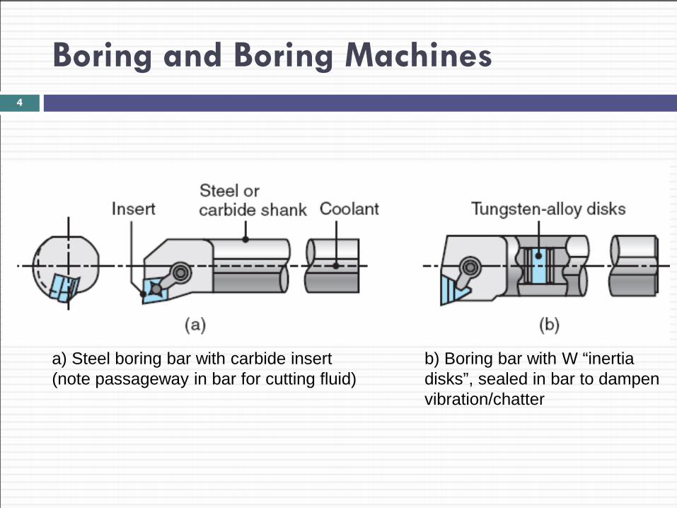
Cutting tools mounted on boring bar (next slide) Boring bars:
Used to reach full length of bore Must be stiff to minimize tool deflection & maintain dimen. acc. Designed, built with capabilities to dampen vibration/chatter ⇒ better to use material with high elastic modulus (e.g. WC)
3
Boring and Boring Machines 4
a) Steel boring bar with carbide insert (note passageway in bar for cutting fluid)
b) Boring bar with W “inertia disks”, sealed in bar to dampen vibration/chatter
Boring and Boring Machines
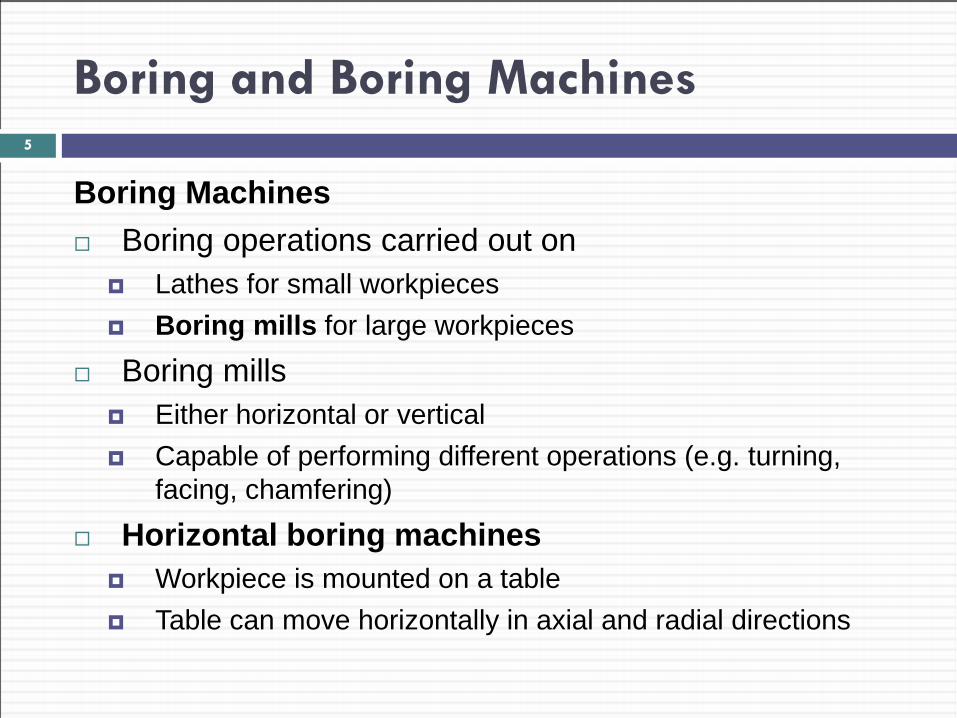
Boring Machines Boring operations carried out on
Lathes for small workpieces Boring mills for large workpieces
Boring mills Either horizontal or vertical Capable of performing different operations (e.g. turning,
facing, chamfering)
Horizontal boring machines Workpiece is mounted on a table Table can move horizontally in axial and radial directions
5
Boring and Boring Machines
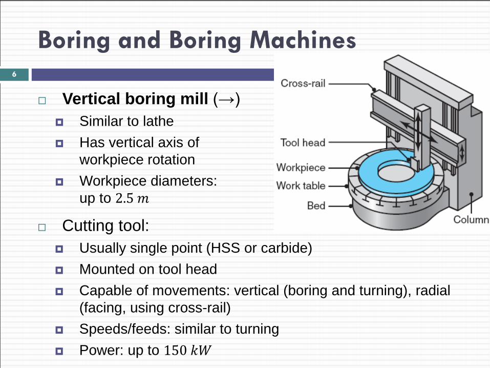
Vertical boring mill (→) Similar to lathe Has vertical axis of
workpiece rotation Workpiece diameters:
up to 2.5 𝑚
6
Cutting tool: Usually single point (HSS or carbide) Mounted on tool head Capable of movements: vertical (boring and turning), radial
(facing, using cross-rail) Speeds/feeds: similar to turning Power: up to 150 𝑘𝑘
Boring and Boring Machines
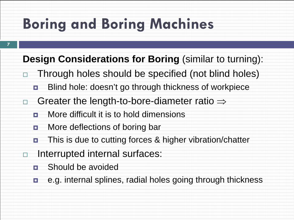
Design Considerations for Boring (similar to turning): Through holes should be specified (not blind holes)
Blind hole: doesn’t go through thickness of workpiece
Greater the length-to-bore-diameter ratio ⇒ More difficult it is to hold dimensions More deflections of boring bar This is due to cutting forces & higher vibration/chatter
Interrupted internal surfaces: Should be avoided e.g. internal splines, radial holes going through thickness
7
Drilling, Drills, and Drilling Machines
Most products have many holes in them e.g. for rivets on plane wings e.g. for bolts in engine blocks
Holes used for: assembly with fasteners (e.g. screws, bolts, rivets) design purposes (e.g. weight reduction, ventilation) appearance
Hole making: Among most important operations in manufacturing Drilling is major, common hole-making process Cost is among highest machining costs in car engine prodon
8
Drilling, Drills, and Drilling Machines: Drills
Drill properties: Have high length-to-diameter ratios (see next slide) Thus, capable of producing deep holes Caution: drills are flexible ⇒ should be used with care to drill holes accurately and to prevent breakage
Drilling Marks: Drills leave burr* on bottom surface upon breakthrough ⇒ requires deburring operations
Rotary motion of drilling ⇒ holes with “circumferential marks” on walls
9
Drilling, Drills, and Drilling Machines: Drills
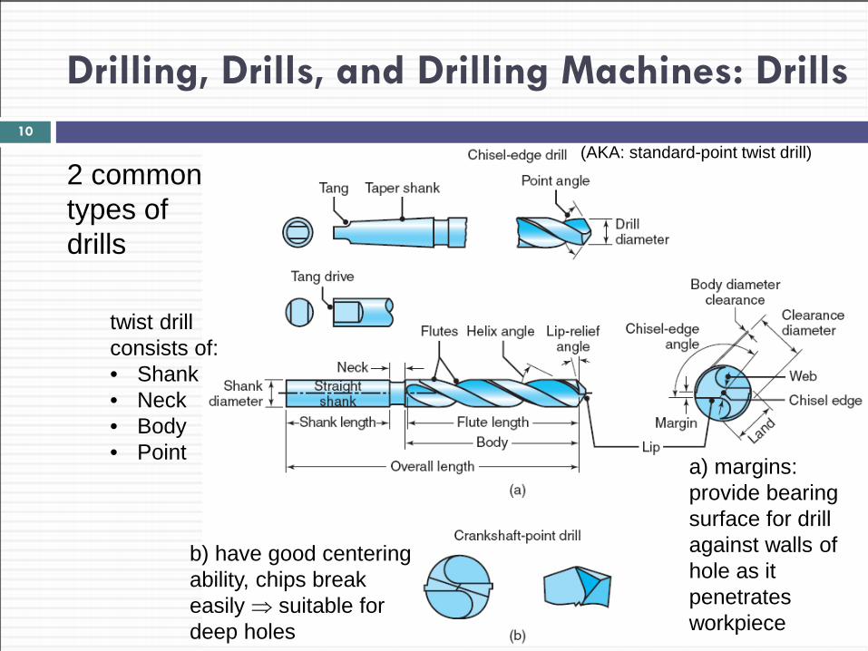
2 common types of drills
10
a) margins: provide bearing surface for drill against walls of hole as it penetrates workpiece
b) have good centering ability, chips break easily ⇒ suitable for deep holes
(AKA: standard-point twist drill)
twist drill consists of: • Shank • Neck • Body • Point
Drilling, Drills, and Drilling Machines: Drills
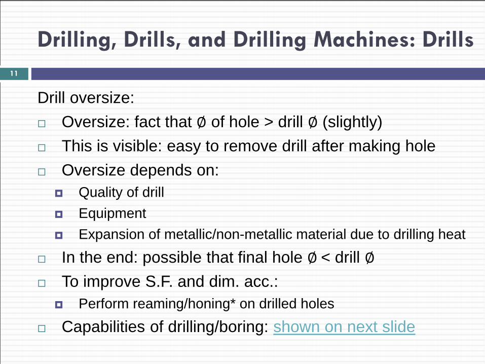
Drill oversize: Oversize: fact that ∅ of hole > drill ∅ (slightly) This is visible: easy to remove drill after making hole Oversize depends on:
Quality of drill Equipment Expansion of metallic/non-metallic material due to drilling heat
In the end: possible that final hole ∅ < drill ∅ To improve S.F. and dim. acc.:
Perform reaming/honing* on drilled holes
Capabilities of drilling/boring: shown on next slide
11
Drilling, Drills, and Drilling Machines: Drills
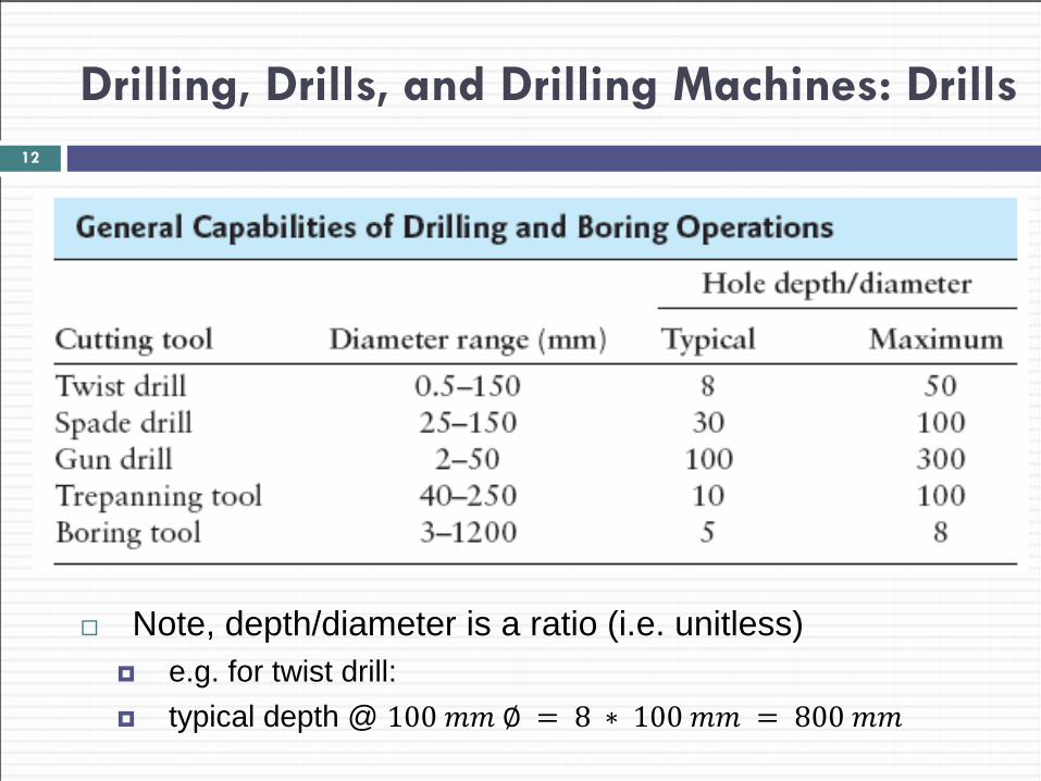
Note, depth/diameter is a ratio (i.e. unitless) e.g. for twist drill: typical depth @ 100 𝑚𝑚 ∅ = 8 ∗ 100 𝑚𝑚 = 800 𝑚𝑚
12
Drilling, Drills, and Drilling Machines: Drills
Twist Drill Most common drill: conventional standard-point twist drill Geometry of drill point:
normal rake angle and 𝑉 of cutting edge vary with distance from center of drill
Main features of twist drill (typical angles): 1. Point angle (118° 𝑡𝑡 135°) 2. Lip-relief angle (7° 𝑡𝑡 15°) 3. Chisel-edge angle (125° 𝑡𝑡 135°) 4. Helix angle (15° 𝑡𝑡 30°)
13
Drilling, Drills, and Drilling Machines: Drills
Cont. Twist Drill Grooves in drills:
Spiral grooves run along length of drill Chips: guided through grooves, upward Grooves: also allow cutting fluid to reach cutting edges Some drills have internal longitudinal holes for cutting fluids (a)
⇒ lubrication, cooling, flushing chips Drills have chip-breaker feature ground along cutting edges
Drill angles (chosen carefully): Produce accurate holes Minimize drilling forces and torque Increase drill life Small change in angles ⇒ great change in performance*
14
Drilling, Drills, and Drilling Machines: Drills
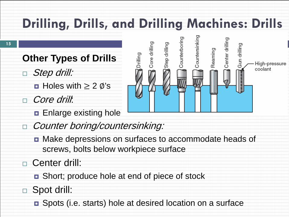
Other Types of Drills Step drill:
Holes with ≥ 2 ∅’s
Core drill: Enlarge existing hole
15
Counter boring/countersinking: Make depressions on surfaces to accommodate heads of
screws, bolts below workpiece surface
Center drill: Short; produce hole at end of piece of stock
Spot drill: Spots (i.e. starts) hole at desired location on a surface
Drilling, Drills, and Drilling Machines: Drills
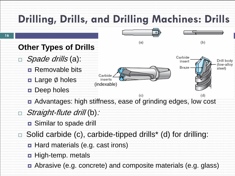
Other Types of Drills Spade drills (a):
Removable bits Large ∅ holes Deep holes
16
Advantages: high stiffness, ease of grinding edges, low cost
Straight-flute drill (b): Similar to spade drill
Solid carbide (c), carbide-tipped drills* (d) for drilling: Hard materials (e.g. cast irons) High-temp. metals Abrasive (e.g. concrete) and composite materials (e.g. glass)
(indexable)
Drilling, Drills, and Drilling Machines: Drills
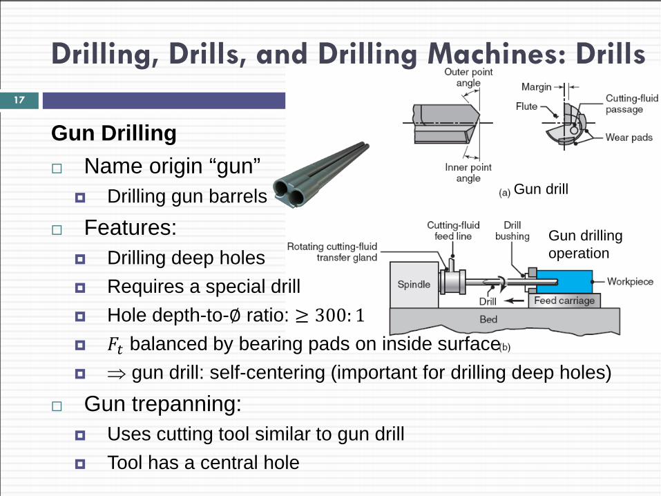
Gun Drilling Name origin “gun”
Drilling gun barrels
Features: Drilling deep holes Requires a special drill Hole depth-to-∅ ratio: ≥ 300: 1 𝐹𝑡 balanced by bearing pads on inside surface ⇒ gun drill: self-centering (important for drilling deep holes)
Gun trepanning: Uses cutting tool similar to gun drill Tool has a central hole
17
Gun drill
Gun drilling operation
Drilling, Drills, and Drilling Machines: Drills
Cont. Gun Drilling Cutting fluid
Forced under high pressure through passage in drill body (fig a) Cooling and lubrication effect Also: flushes out chips that could be trapped in deep holes ⇒ chips don’t interfere with drilling operation ⇒ no need to retract tool to clear chips (i.e. unlike twist drills)
18
Drilling, Drills, and Drilling Machines: Drills
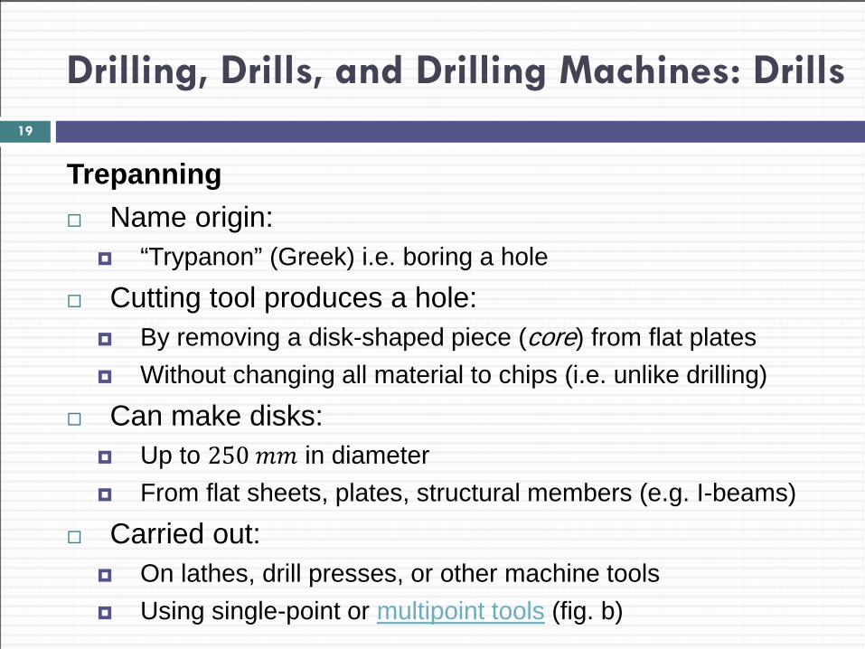
Trepanning Name origin:
“Trypanon” (Greek) i.e. boring a hole
Cutting tool produces a hole: By removing a disk-shaped piece (core) from flat plates Without changing all material to chips (i.e. unlike drilling)
Can make disks: Up to 250 𝑚𝑚 in diameter From flat sheets, plates, structural members (e.g. I-beams)
Carried out: On lathes, drill presses, or other machine tools Using single-point or multipoint tools (fig. b)
19
Drilling, Drills, and Drilling Machines: Drills
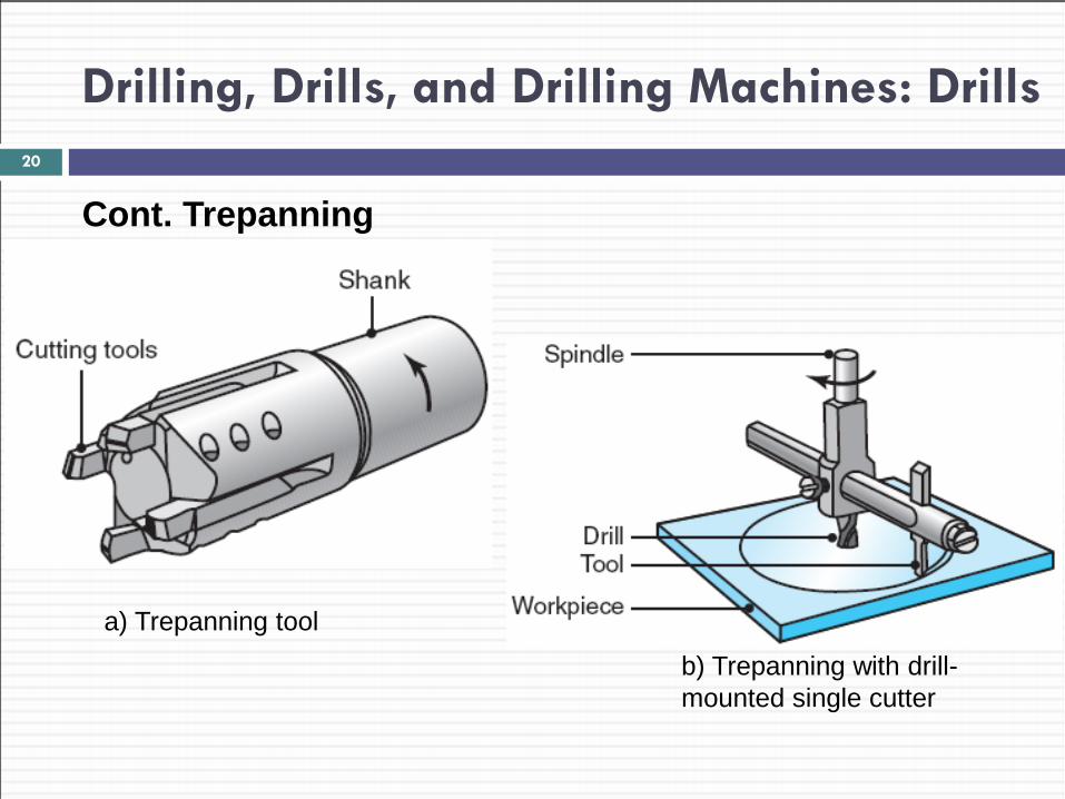
Cont. Trepanning 20
a) Trepanning tool b) Trepanning with drill-mounted single cutter
Drilling, Drills, and Drilling Machines: Material-removal Rate in Drilling
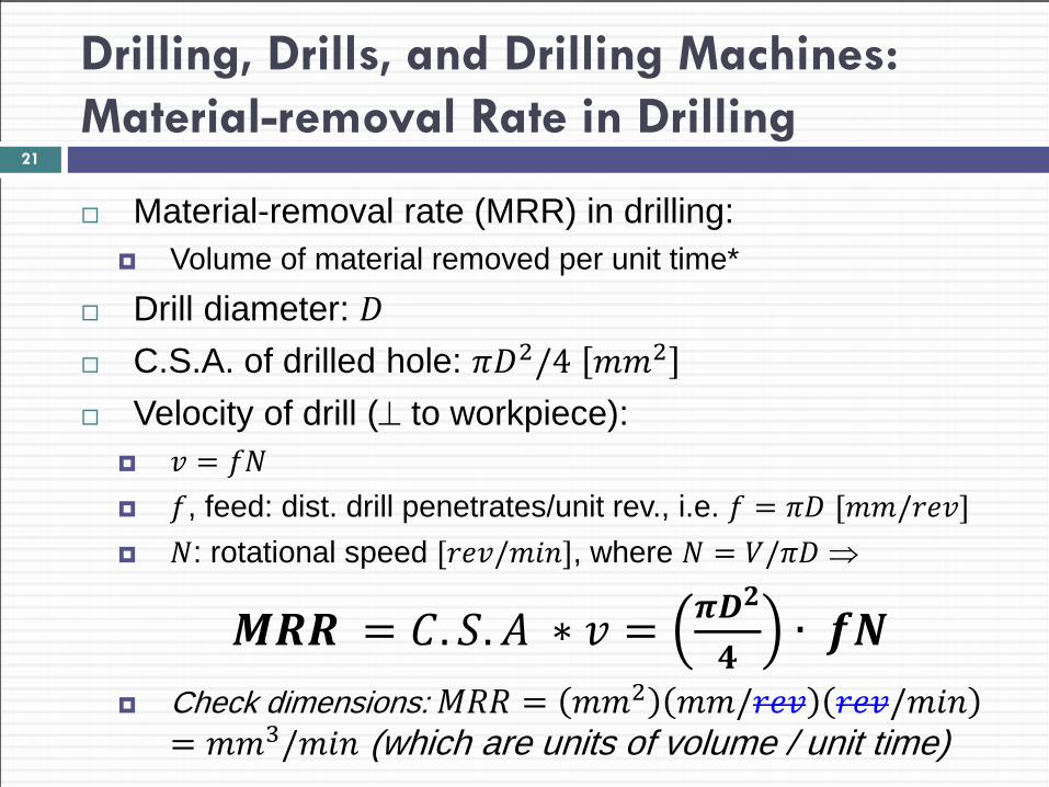
Material-removal rate (MRR) in drilling: Volume of material removed per unit time*
Drill diameter: 𝐷 C.S.A. of drilled hole: 𝜋𝐷2/4 𝑚𝑚2 Velocity of drill (⊥ to workpiece):
𝑣 = 𝑓𝑓 𝑓, feed: dist. drill penetrates/unit rev., i.e. 𝑓 = 𝜋𝐷 [𝑚𝑚/𝑟𝑟𝑣] 𝑓: rotational speed [𝑟𝑟𝑣/𝑚𝑚𝑚], where 𝑓 = 𝑉/𝜋𝐷 ⇒
𝑴𝑴𝑴 = 𝐶. 𝑆.𝐴 ∗ 𝑣 = 𝝅𝑫𝟐
𝟒∙ 𝒇𝒇
Check dimensions: 𝑀𝑀𝑀 = 𝑚𝑚2 𝑚𝑚/𝑟𝑟𝑣 𝑟𝑟𝑣/𝑚𝑚𝑚= 𝑚𝑚3/𝑚𝑚𝑚 (which are units of volume / unit time)
21
Drilling, Drills, and Drilling Machines: Thrust Force and Torque
Thrust force (𝐹𝑡) Acts perpendicular to hole axis (i.e. radially or sideways) Excessive 𝐹𝑡 ⇒ Drill: bends or breaks Workpiece: distorted (esp. if it does not have sufficient stiffness*) or Workpiece: slips into workholding fixture
𝐹𝑡 depends on: 1. Strength of the workpiece material 2. Feed 3. Rotational speed 4. Drill diameter 5. Drill geometry 6. Cutting fluid
22
Drilling, Drills, and Drilling Machines: Thrust Force and Torque
Finding 𝐹𝑡: Accurate calculation is difficult Range: few 𝑓 for small drills to 100 𝑘𝑓 for high-strength materials with large drills
Experimental data: helps in using drills
23
Drilling, Drills, and Drilling Machines: Thrust Force and Torque
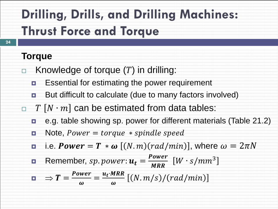
Torque Knowledge of torque (𝑇) in drilling:
Essential for estimating the power requirement But difficult to calculate (due to many factors involved)
𝑇 𝑓 ∙ 𝑚 can be estimated from data tables: e.g. table showing sp. power for different materials (Table 21.2) Note, 𝑃𝑡𝑃𝑟𝑟 = 𝑡𝑡𝑟𝑡𝑡𝑟 ∗ 𝑠𝑠𝑚𝑚𝑠𝑠𝑟 𝑠𝑠𝑟𝑟𝑠 i.e. 𝑷𝑷𝑷𝑷𝑷 = 𝑻 ∗ 𝝎 𝑓.𝑚 𝑟𝑟𝑠/𝑚𝑚𝑚 , where 𝜔 = 2𝜋𝑓 Remember, 𝑠𝑠.𝑠𝑡𝑃𝑟𝑟:𝒖𝒕 = 𝑷𝑷𝑷𝑷𝑷
𝑴𝑴𝑴 𝑘 ∙ 𝑠/𝑚𝑚3
⇒ 𝑻 = 𝑷𝑷𝑷𝑷𝑷𝝎
= 𝒖𝒕∙𝑴𝑴𝑴𝝎
𝑓.𝑚/𝑠 / 𝑟𝑟𝑠/𝑚𝑚𝑚
24
Drilling, Drills, and Drilling Machines: Thrust Force and Torque
EXAMPLE 23.4 Material-removal Rate and Torque in Drilling A hole is being drilled in a block of magnesium alloy with a 10 −𝑚𝑚 drill bit at a feed of 0.2 𝑚𝑚/𝑟𝑟𝑣 and with the spindle running at 𝑓 = 800 𝑟𝑠𝑚. Calculate the material-removal rate and the torque on the drill.
25
Drilling, Drills, and Drilling Machines: Thrust Force and Torque
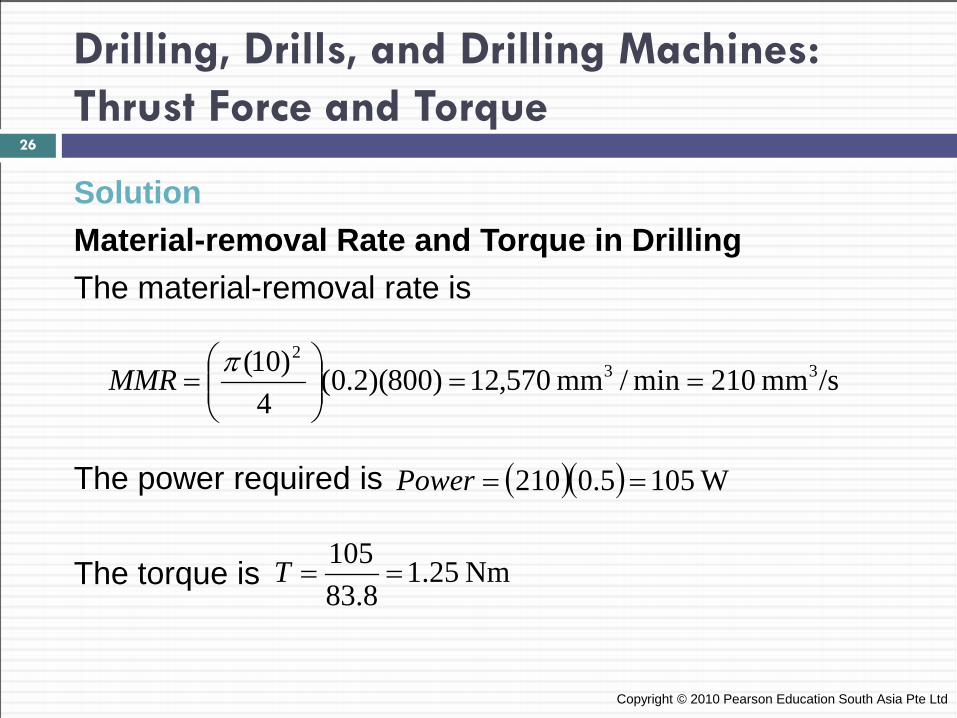
Solution Material-removal Rate and Torque in Drilling The material-removal rate is The power required is The torque is
Copyright © 2010 Pearson Education South Asia Pte Ltd
/smm 210min/mm 570,12)800)(2.0(4
)10( 332
==
=
πMMR
( )( ) W1055.0210 ==Power
Nm 25.18.83
105==T
26
Drilling, Drills, and Drilling Machines: Drill Materials and Sizes
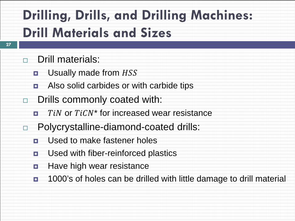
Drill materials: Usually made from 𝐻𝑆𝑆 Also solid carbides or with carbide tips
Drills commonly coated with: 𝑇𝑚𝑓 or 𝑇𝑚𝐶𝑓* for increased wear resistance
Polycrystalline-diamond-coated drills: Used to make fastener holes Used with fiber-reinforced plastics Have high wear resistance 1000’s of holes can be drilled with little damage to drill material
27
Drilling, Drills, and Drilling Machines: Drill Materials and Sizes
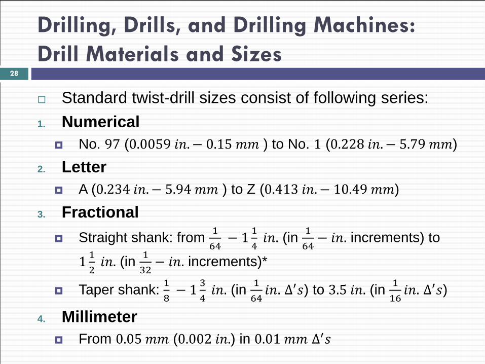
Standard twist-drill sizes consist of following series: 1. Numerical
No. 97 (0.0059 𝑚𝑚.− 0.15 𝑚𝑚 ) to No. 1 (0.228 𝑚𝑚.− 5.79 𝑚𝑚)
2. Letter A (0.234 𝑚𝑚.− 5.94 𝑚𝑚 ) to Z (0.413 𝑚𝑚.− 10.49 𝑚𝑚)
3. Fractional Straight shank: from 1
64 − 1 1
4 𝑚𝑚. (in 1
64− 𝑚𝑚. increments) to
1 12
𝑚𝑚. (in 132− 𝑚𝑚. increments)*
Taper shank: 18
− 1 34
𝑚𝑚. (in 164𝑚𝑚. ∆′𝑠) to 3.5 𝑚𝑚. (in 1
16𝑚𝑚. ∆′𝑠)
4. Millimeter From 0.05 𝑚𝑚 (0.002 𝑚𝑚.) in 0.01 𝑚𝑚 ∆′𝑠
28
Drilling, Drills, and Drilling Machines: Drilling Practice
Drill chucks: Used to hold drills (and similar hole-making tools) Tightened with/without keys Special chucks Have quick change features Do not require stopping the spindle Available for use in production machinery
Lateral deflection of drill: Drills do not have a centering action ⇒ tend to “walk” on workpiece surface at start of operation Problem severe with small-D long drills, may lead to failure
29

Drilling, Drills, and Drilling Machines: Drilling Practice
Avoiding lateral deflection of drill (at start of drill): 1. Guide drill using fixtures 2. Use center drill to make small starting hole before drilling Usually @ 60° point angle
3. Grind drill point to an S shape (important with CNC machines) This has a self-centering characteristic ⇒ no need for center-drilling Produces accurate holes with improved drill life
4. Use centering punch ⇒ produces initial impression 5. Add dimples (or other features) in cast or forged blank
Copyright © 2010 Pearson Education South Asia Pte Ltd
30
Drilling, Drills, and Drilling Machines: Drilling Practice
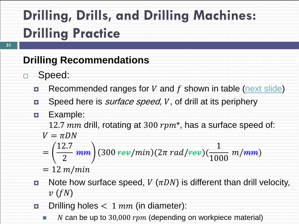
Drilling Recommendations Speed:
Recommended ranges for 𝑉 and 𝑓 shown in table (next slide) Speed here is surface speed, 𝑉, of drill at its periphery Example:
12.7 𝑚𝑚 drill, rotating at 300 𝑟𝑠𝑚*, has a surface speed of: 𝑉 = 𝜋𝐷𝑓
=12.7
2 𝑚𝑚 300 𝑟𝑟𝑣/𝑚𝑚𝑚 (2𝜋 𝑟𝑟𝑠/𝑟𝑟𝑣)(
11000
𝑚/𝑚𝑚)
= 12 𝑚/𝑚𝑚𝑚 Note how surface speed, 𝑉 (𝜋𝐷𝑓) is different than drill velocity,
𝑣 (𝑓𝑓) Drilling holes < 1 𝑚𝑚 (in diameter): 𝑓 can be up to 30,000 𝑟𝑠𝑚 (depending on workpiece material)
31
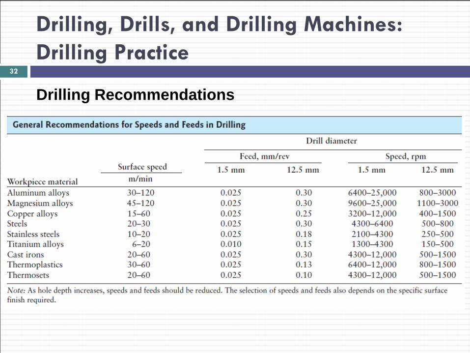
Drilling, Drills, and Drilling Machines: Drilling Practice
Drilling Recommendations
32
Drilling, Drills, and Drilling Machines: Drilling Practice
Drilling Recommendations Feed:
Feed in drilling: dist. drill travels into workpiece per revolution Recommendation: for most workpiece materials:
drills with 𝐷 = 1.5 𝑚𝑚 should have 𝑓 = 0.025 𝑚𝑚/𝑟𝑟𝑣 Example:
A 1.5 𝑚𝑚− 𝐷 drill rotating at 2000 𝑟𝑠𝑚, has linear speed of: 𝑣 = 𝑓 ∗ 𝑓 = 0.025 𝑚𝑚/𝑟𝑟𝑣 2000 𝑟𝑟𝑣/𝑚𝑚𝑚 = 50 𝑚𝑚/𝑚𝑚𝑚
33
Drilling, Drills, and Drilling Machines: Drilling Practice
Drilling Recommendations Chip removal during drilling:
Can be difficult Especially: deep holes in soft and ductile workpiece materials To avoid this: Retract drill periodically (“pecking”), then: Removing chips accumulated along drill flutes Otherwise: drill may break due to high 𝑇, or
“walk-off” location and produce mis-shaped hole
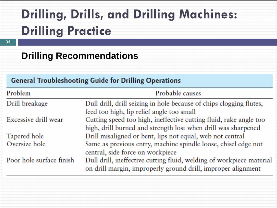
Table: shows guide to general problems in drilling operations
34
Drilling, Drills, and Drilling Machines: Drilling Practice
Drilling Recommendations
35
Drilling, Drills, and Drilling Machines: Drilling Practice
Drill Reconditioning Drills reconditioned by grinding, either:
Manually (i.e. by hand), or With special fixtures
Reconditioning: especially important with CNC machines Hand grinding:
Difficult Requires considerable skill to produce symmetric cutting edges
Grinding on fixtures: Accurate Done on special computer controlled grinders
Coated drills can be recoated
36
Drilling, Drills, and Drilling Machines: Drilling Practice
Measuring Drill Life Drill life measured by no. of holes drilled:
Before they become dull, and Need to be re-worked or replaced
Determining drill life experimentally: Clamping material on dynamometer/force transducer Drilling number of holes Recording 𝑇 or 𝐹𝑡 during each operation After certain no. of holes: 𝑇 & 𝐹𝑡 ↑ since tool becomes dull Drill life here is: no. of holes drilled until this transition begins
Other techniques to measure drill life: Monitoring vibrations and acoustic emissions (Ch. 21: tool life)
37
Drilling, Drills, and Drilling Machines: Drilling Machines
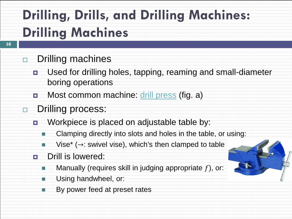
Drilling machines Used for drilling holes, tapping, reaming and small-diameter
boring operations Most common machine: drill press (fig. a)
Drilling process: Workpiece is placed on adjustable table by: Clamping directly into slots and holes in the table, or using: Vise* (→: swivel vise), which’s then clamped to table
Drill is lowered: Manually (requires skill in judging appropriate 𝑓), or: Using handwheel, or: By power feed at preset rates
38
Drilling, Drills, and Drilling Machines: Drilling Machines
39
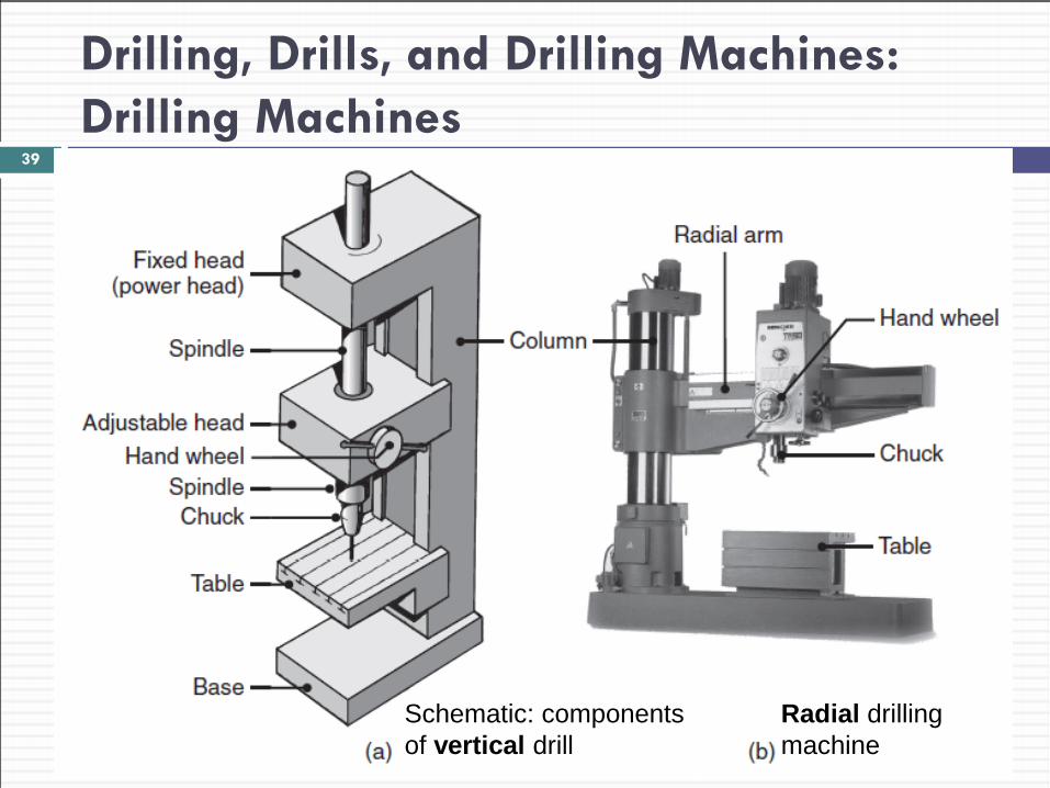
Schematic: components of vertical drill
Radial drilling machine
Drilling, Drills, and Drilling Machines: Drilling Machines
Drill presses: Designated by largest workpiece 𝐷 accommodated on table Typical range 𝐷 = 150 𝑡𝑡 1250 𝑚𝑚
Adjusting spindle speed Necessary to maintain proper cutting speed at drill cutting edge Allows using different drill sizes
Types of drilling machines (traditional machines) 1. Simple: bench type drills, used to drill small-𝐷 holes 2. Large: radial drills (fig. b), used for large workpieces 3. Universal drilling machines: drill head can be swiveled to drill
holes at an angle
40
Drilling, Drills, and Drilling Machines: Drilling Machines
Cont. Types of drilling machines (developments): 4. Numerically controlled three-axis drilling machines (fig.): Operations performed automatically & in desired sequence using turret Turret holds different tooling tools
5. Gang drilling: Drilling machines with multiple spindles* Used for high-production-rate operations Capable of drilling 50 holes in 1 cycle (different sizes, depths, locations) Also used for reaming, counterboring operations
6. Numerical-control turret drilling machines Replacing machine tools and gang-drilling machines
7. Special drilling machines e.g. produce holes in continuous hinges (e.g. piano hinges) Horizontal and produce holes up to 3 −𝑚 long segments per cycle
41
Drilling, Drills, and Drilling Machines: Drilling Machines
42
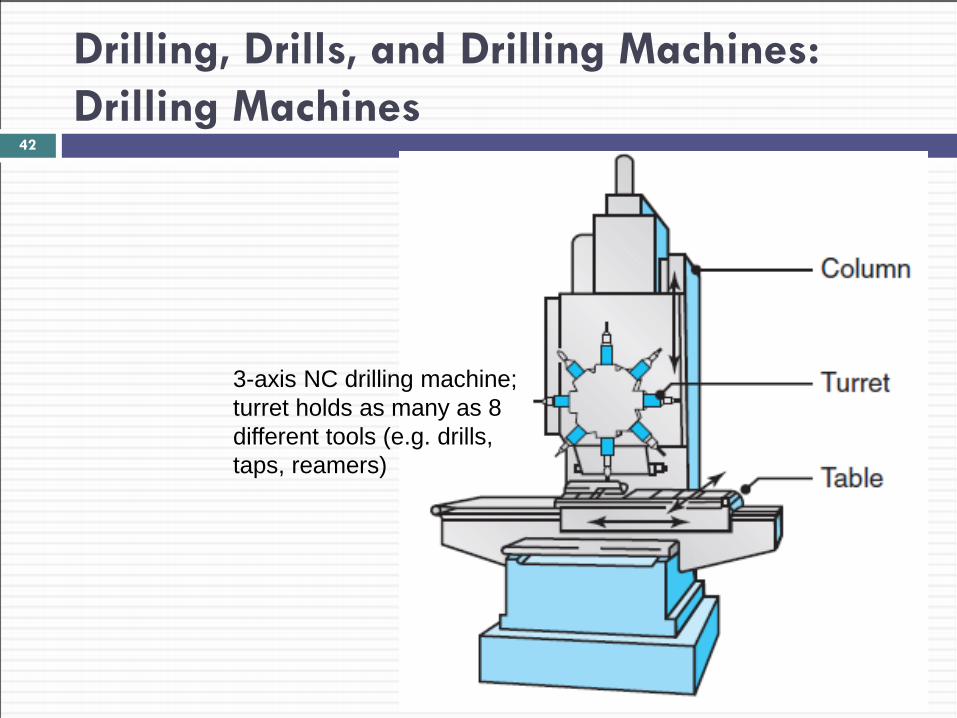
3-axis NC drilling machine; turret holds as many as 8 different tools (e.g. drills, taps, reamers)
Drilling, Drills, and Drilling Machines: Drilling Machines
Workholding devices: Ensure workpiece is located properly Keep workpiece from slipping or rotating during drilling Available in various designs Important features: 3-point locating (for accuracy) 3-D workholding for secure fixtures
43
Drilling, Drills, and Drilling Machines: Design Considerations for Drilling
Basic design guidelines for drilling: 1. Designs should allow holes to be drilled On flat surfaces and ⊥ to drill motion Otherwise: drills deflect and hole will not be located properly
2. Interrupted hole surfaces should be avoided This ensures: dim. acc., longer drill life, avoids vibrations
3. Hole bottoms should match standard drill-point angles 4. Through holes are preferred over blind holes 5. Dimples should be provided: When pre-existing holes not possible, to reduce drill “walk-off”
6. Parts should be designed to drill with minimum of fixturing 7. Blind holes: drill deeper than subsequent reaming/tapping
44

Reaming and Reamers
Reaming: operation used to: Make existing hole dimensionally more accurate (than drilling) Improve surface finish
Sequence to produce accurate holes in workpieces: 1. Centering 2. Drilling 3. Boring 4. Reaming
For even better accuracy & surface finish, holes may be burnished, or internally ground and honed
Copyright © 2010 Pearson Education South Asia Pte Ltd
45

Reaming and Reamers
Reamer: Multiple-cutting edge tool Has straight or helically fluted edges (see below) Removes min. of 0.2 𝑚𝑚 on diameter of drilled hole Harder metals: removes 0.13 𝑚𝑚 Removing smaller layers ⇒ Reamer may be damaged Hole surface may become burnished
46
Terminology for helical reamer
Rose reamers
Reaming and Reamers
Types of Reamers Hand reamers
Straight or have tapered end in the first third of their length
Machine (AKA chucking) reamers: Mounted in a chuck and operated by a machine Available in 2 types: Rose reamers (last slide): remove considerable amount of material Fluted reamers: used for light cuts: 0.1 𝑚𝑚 in hole diameter
Shell reamers Used for holes larger than 20 𝑚𝑚
47
Reaming and Reamers
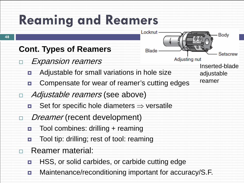
Cont. Types of Reamers Expansion reamers
Adjustable for small variations in hole size Compensate for wear of reamer’s cutting edges
Adjustable reamers (see above) Set for specific hole diameters ⇒ versatile
Dreamer (recent development) Tool combines: drilling + reaming Tool tip: drilling; rest of tool: reaming
Reamer material: HSS, or solid carbides, or carbide cutting edge Maintenance/reconditioning important for accuracy/S.F.
48
Inserted-blade adjustable reamer
Tapping and Taps
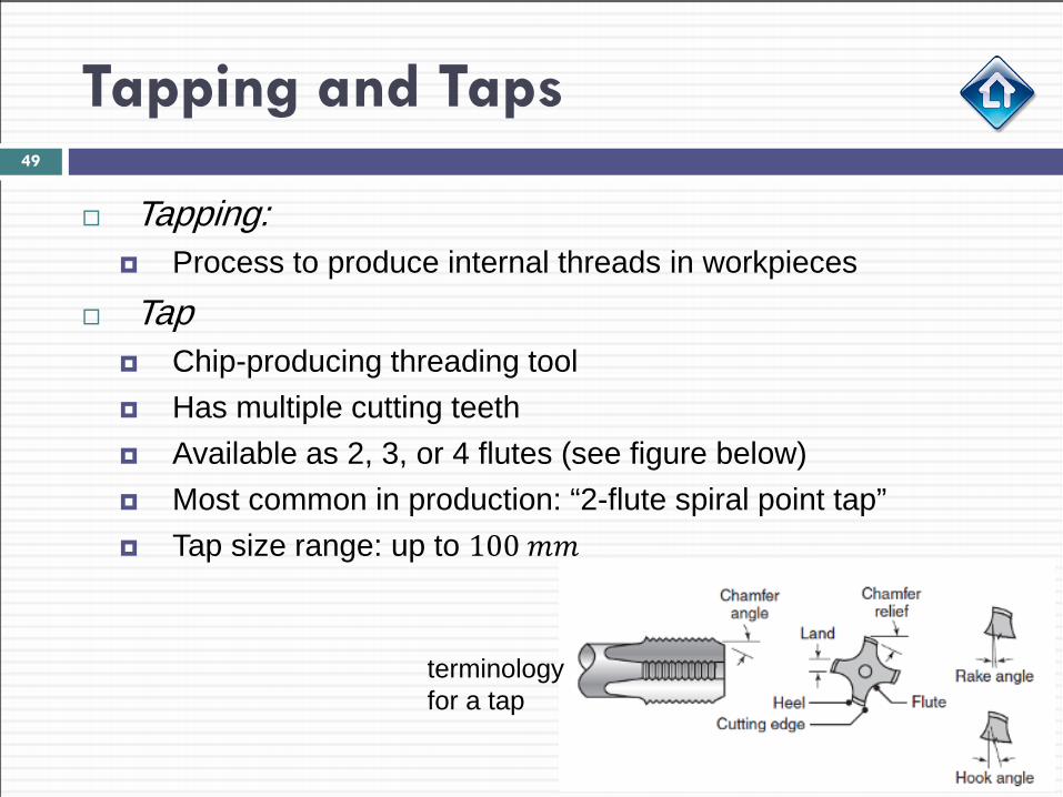
Tapping: Process to produce internal threads in workpieces
Tap Chip-producing threading tool Has multiple cutting teeth Available as 2, 3, or 4 flutes (see figure below) Most common in production: “2-flute spiral point tap” Tap size range: up to 100 𝑚𝑚
49
terminology for a tap
Tapping and Taps
Types of Taps Tapered taps:
Reduce torque required for tapping of through holes
Bottoming taps: Used for tapping blind holes to their full depth
Collapsible taps Used in large-diameter holes
Drapping: Combination of drilling and tapping (in a single tool) Increases tapping productivity Tip: drilling; rest of tool: tapping
50
Tapping and Taps
Removing chips: Problem during tapping (due to small clearances) Chips must be removed Otherwise: large torque ⇒ break the tap Solutions:
Use of cutting fluid Periodic reversal and removal of tap
Result: Effective ways to remove chips Improved tapped hole quality
51
Tapping and Taps
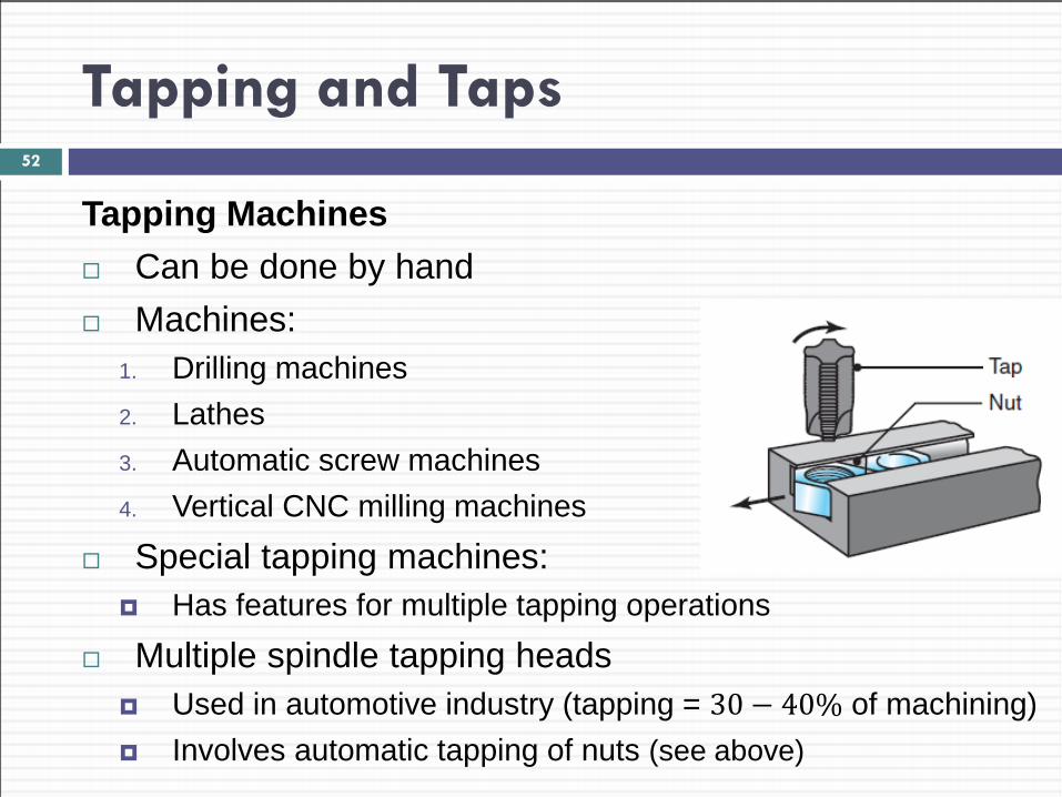
Tapping Machines Can be done by hand Machines:
1. Drilling machines 2. Lathes 3. Automatic screw machines 4. Vertical CNC milling machines
Special tapping machines: Has features for multiple tapping operations
Multiple spindle tapping heads Used in automotive industry (tapping = 30 − 40% of machining) Involves automatic tapping of nuts (see above)
52
Tapping and Taps
Tapping Properties Tap life: as high as 10,000 holes Taps usually made of HSS High-speed tapping:
Increases productivity: surface speeds: as high as 100 𝑚/min Operating speeds: as high as 5000 𝑟𝑠𝑚
Self-reversing tapping systems: used with CNC machines Recent developments:
Applying cutting fluid to cutting zone through spindle and hole in the tap (like in boring)
Also helps flush chips out of the hole
53