maps product description - hf · (maps) product description . 2 ... dessoft tools are used...
TRANSCRIPT
Mitsubishi Adroit Process Suite (MAPS)
Product Description
2
Table of Contents
INTRODUCTION TO THE MAPS SOLUTION ............................................................... 3
1.1. Introduction and summary ............................................................................. 3
2. INTRODUCTION TO THE COMPANIES ......................................................................... 4
2.1. ADROIT Technologies .................................................................................... 4
2.2. DESSOFT ..................................................................................................... 4
3. INTRODUCTION TO THE MAPS SOLUTION .................................................................. 5
3.1. MAPS – LIFE CYCLE ENGINEERING .................................................................. 5
3.1.1. INTRODUCTION ..................................................................................... 5
3.2. The Technologies and Products ....................................................................... 6
3.2.1. INTRODUCTION ..................................................................................... 6
3.2.2. THE PLC PROGRAM ................................................................................. 8
3.2.3. THE SCADA ........................................................................................... 8
3.3. Overview of user screens and operations ......................................................... 9
3.3.1. INTRODUCTION ..................................................................................... 9
3.3.2. DESIGN PROCESS .................................................................................. 9
3.3.3. BUILD THE SCADA ............................................................................... 11
3.3.4. BUILD THE PLC .................................................................................... 13
3.4. Features and benefits of MAPS ..................................................................... 14
3.4.1. STANDARDS APPROACH TO PROJECTS ................................................... 14
3.4.2. STANDARD, SETUP AND DIAGNOSTIC FACEPLATES .................................. 15
3.4.3. SINGLE POINT OF CONFIGURATION ....................................................... 16
3.4.4. WORLD-CLASS SCADA .......................................................................... 16
3.4.5. ON-GOING LIFE-CYCLE MANAGEMENT .................................................... 20
3.4.6. AUTOMATICALLY GENERATED PLC AND SCADA PROJECTS ........................ 20
3.4.7. AUTOMATICALLY GENERATED REPORTS .................................................. 20
3.4.8. AUTOMATICALLY GENERATED MANAGEMENT SCREENS ............................ 20
3.4.9. EASY ACCESS TO PLC PROGRAM OBJECTS FOR DIAGNOSTICS AND FAULT
FINDING ........................................................................................................ 21
3.4.10. EASY ACCESS TO PLC DIAGNOSTICS .................................................... 22
3.5. Industries and applications .......................................................................... 23
3
INTRODUCTION TO THE MAPS SOLUTION
1.1. Introduction and summary
The Mitsubishi Adroit Process Suite (MAPS) software solution is collaboration between the following
Companies; Mitsubishi Electric, Adroit Technologies and DesSoft.
• Mitsubishi Electric manufacture PLC’s and Drives for the automation industry
• Adroit Technologies are the developers of the Adroit SCADA and associated software
• DesSoft are the developers of database driven electrical and instrumentation design and
documentation software
MAPS is focused around offering an integrated PLC/SCADA programming and management tool
that works seamlessly with the Adroit SCADA, the Mitsubishi GX-IEC Developer/GX Works 2
software and the DesSoft engineering design software. It needs to be noted that MAPS does not
require users to use the DesSoft tools in order to get engineering value out of the MAPS product itself.
MAPS delivers value along the entire life-cycle and value chain of any automation solution. From
initial process design, the engineering phase and finally addressing the shortcomings of current
offerings and solutions around the commissioning, handover and operations phase of an automation project.
Process Houses and Systems Integrators save time and can deliver projects quicker and of higher
quality. Customers benefit from the integrated document management and reporting as well as the on-going ability to maintain the solution and documents.
The result is an integrated life-cycle management solution for the automation industry.

4
2. INTRODUCTION TO THE COMPANIES
2.1. ADROIT Technologies
Adroit Technologies has been developing industrial real-time software since 1983. 25 years later
with over 15000 seats in over 10 different countries, it’s products can be found in almost all industries including:
• Automotive
• Energy Management
• Telecommunications and Network Management
• Mining and Mineral Processing
• Water and Electrical Utilities
• Building and Facilities Management
• Nuclear
• Military
• Transport
• Shipping
The products are off-the-shelf, tried and tested and built with the highest quality and the Company boasts many listed and blue-chip customers across the globe.
There is a lot of further information on our website on http://www.adroit.co.za feel free to browse the
site or contact us should you require any further information.
The Company focuses on delivering “Solutions Focused Software” has three main products, the
Adroit it’s flagship Supervisory Control and Data Acquisition Software (SCADA), Alarm Management and Analysis software and the Adroit SCADA Intelligence software.
The solutions are designed to work together to offer easy to use data acquisition, visualization and the associated productivity tools that allow customers to drive productivity through process insight.
2.2. DESSOFT
DesSoft are the developers of a suite of design software packages that are state-of-the-art, open-
ended, database driven, productive focused software systems to create plant design documentation
like P&ID, Loop Connection, Termination Connection, Motor Schematic, Single Line, Power Reticulation and many more diagrams.
5
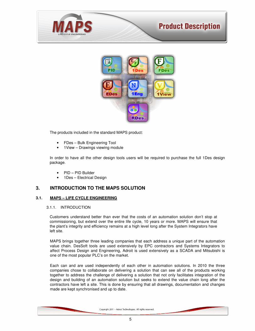
The products included in the standard MAPS product:
• FDes – Bulk Engineering Tool
• 1View – Drawings viewing module
In order to have all the other design tools users will be required to purchase the full 1Des design package.
• PID – PID Builder
• 1Des – Electrical Design
3. INTRODUCTION TO THE MAPS SOLUTION
3.1. MAPS – LIFE CYCLE ENGINEERING
3.1.1. INTRODUCTION
Customers understand better than ever that the costs of an automation solution don’t stop at
commissioning, but extend over the entire life cycle, 10 years or more. MAPS will ensure that
the plant’s integrity and efficiency remains at a high level long after the System Integrators have
left site.
MAPS brings together three leading companies that each address a unique part of the automation
value chain. DesSoft tools are used extensively by EPC contractors and Systems Integrators to
affect Process Design and Engineering, Adroit is used extensively as a SCADA and Mitsubishi is one of the most popular PLC’s on the market.
Each can and are used independently of each other in automation solutions. In 2010 the three
companies chose to collaborate on delivering a solution that can see all of the products working
together to address the challenge of delivering a solution that not only facilitates integration of the
design and building of an automation solution but seeks to extend the value chain long after the
contractors have left a site. This is done by ensuring that all drawings, documentation and changes made are kept synchronised and up to date.
6
The MAPS 1-Eng bulk engineering tool shall be shipped as standard with MAPS but this would then
facilitate the easy extension should the customer wish to use the full electrical design capability of the DesSoft software suite.
This answers the problems of “drift” between design, construction, integration and what is delivered
“as-built” as well as the gradual degradation of the solution and associated documentation as a customer maintains and develops the process system along the way.
3.2. The Technologies and Products
3.2.1. INTRODUCTION
For many years suppliers and organizations such as the International Standards Authority (ISA)
have been preaching the benefits of a standards driven approach. Whilst reducing flexibility a little - the benefits are significant.
The key to the product and a successful and high-quality automation solution lies in the use of
re-usable objects, standards and structure. To this end the MAPS’s product requires EPC’s,
Project Houses, System Integrators and Customers to alter their thinking around their approach
to projects.
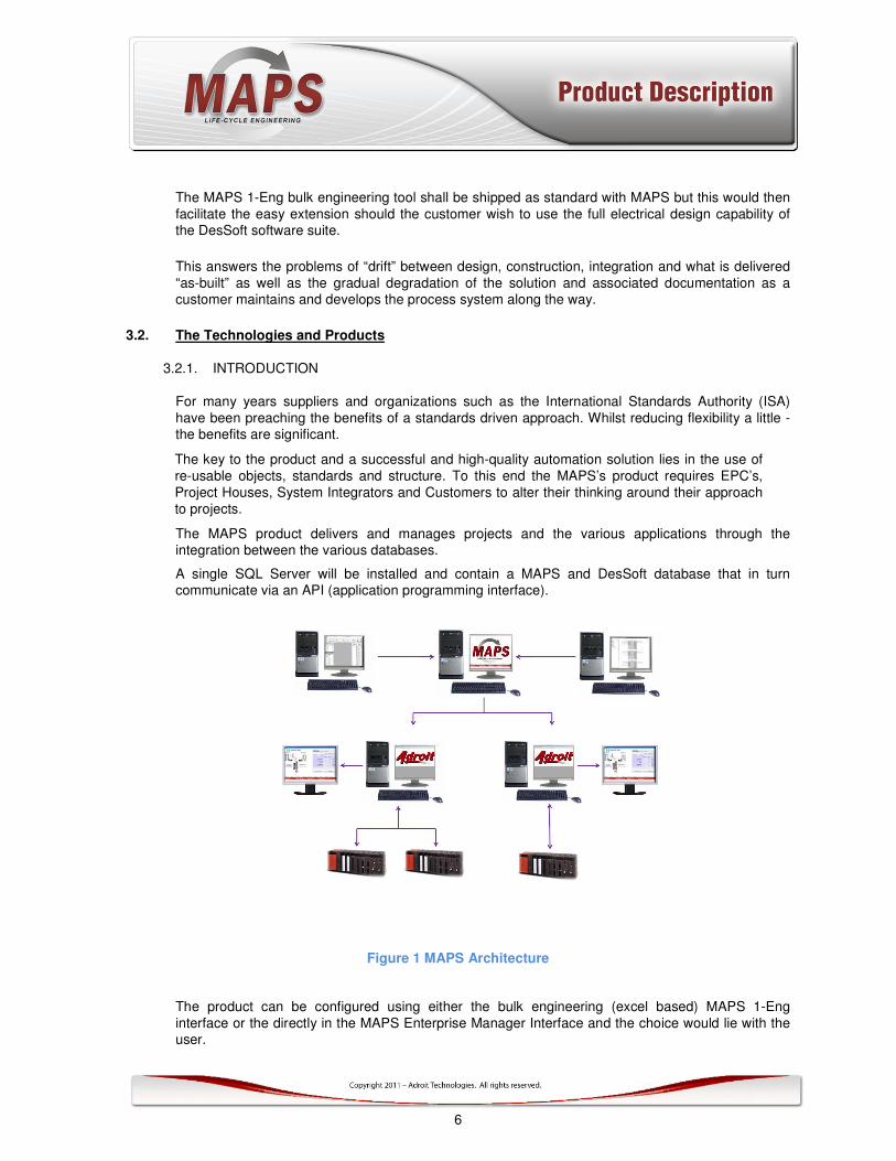
The MAPS product delivers and manages projects and the various applications through the integration between the various databases.
A single SQL Server will be installed and contain a MAPS and DesSoft database that in turn communicate via an API (application programming interface).
Figure 1 MAPS Architecture
The product can be configured using either the bulk engineering (excel based) MAPS 1-Eng
interface or the directly in the MAPS Enterprise Manager Interface and the choice would lie with the user.
7
Should the customer have and use the DesSoft design software the EDes would be the tool as it offers full integration into the electrical design software.
The MAPS software has been designed with the best practices and experience in mind. With more
than 30 standard IEC function blocks matched with SCADA graphics gives users the flexibility of
going with a more complex control structure or a simple control structure. This would very much depend on budget and process type.
Please note this list is dynamic and users should request the latest list of supported FB’s and MAPS objects.
Some examples of these function blocks are
Electrical equipment Templates
DOL_A_v1_0 : Advanced Direct Online Starter (motor)
DOL_B_v1_0 : Basic Direct Online Starter (motor)
DOL_S_v1_0 : Standard Direct Online Starter (motor)
VALVE_D_A_v1_0 : Advanced Double Actuating Valve
VALVE_D_B_v1_0 : Basic Double Actuating Valve
VALVE_D_S_v1_0 : Standard Double Actuating Valve
VALVE_S_A_v1_0 : Advanced Single Actuating Valve
VALVE_S_B_v1_0 : Basic Single Actuating Valve
VALVE_S_S_v1_0 : Standard Single Actuating Valve
Instrumentation equipment Templates
AI_A_v1_0 : Advanced Analog Input
AI_B_v1_0 : Basic Analog Input
AI_S_v1_0 : Standard Analog Input
AO_A_v1_0 : Advanced Analog Output
AO_B_v1_0 : Basic Analog Output
AO_S_v1_0 : Standard Analog Output
DI_A_v1_0 : Advanced Digital Input
DI_B_v1_0 : Basic Digital Input
DI_S_v1_0 : Standard Digital Input
DO_A_v1_0 : Advanced Digital Output
DO_B_v1_0 : Basic Digital Output
DO_S_v1_0 : Standard Digital Output
GS_A_v1_0 : Advanced Group Start
GS_S_v1_0 : Standard Group Start
PID_A_v1_0 : Advanced PID Control
PID_S_v1_0 : Standard PID Control

8
VESSEL_A_v1_0 : Advanced Vessel
VESSEL_B_v1_0 : Basic Vessel
VESSEL_S_v1_0 : Standard Vessel
Note: The more advanced the template the greater the number of signals (scanned tags) required to represent this item of equipment. This can increase the size (and cost) of your required Adroit license - so assign these templates to your equipment carefully.
3.2.2. THE PLC PROGRAM
The result of the MAPS configuration is a structured PLC program containing the FB’s as ordered within an IEC Developer project.
3.2.3. THE SCADA
The result of the MAPS configuration is a complete SCADA project built on the Adroit SCADA product. Including the following:
• PLC Drivers and Devices
• All tags associated with FB’s
• All mimics in structured format containing selected graphic objects. Each graphic object has
associated faceplates to deliver further management capability
• Full navigation
• Logging and Alarming set-up using templates
More details on the features of the SCADA product are contained in the product description appendix.
9
3.3. Overview of user screens and operations
3.3.1. INTRODUCTION
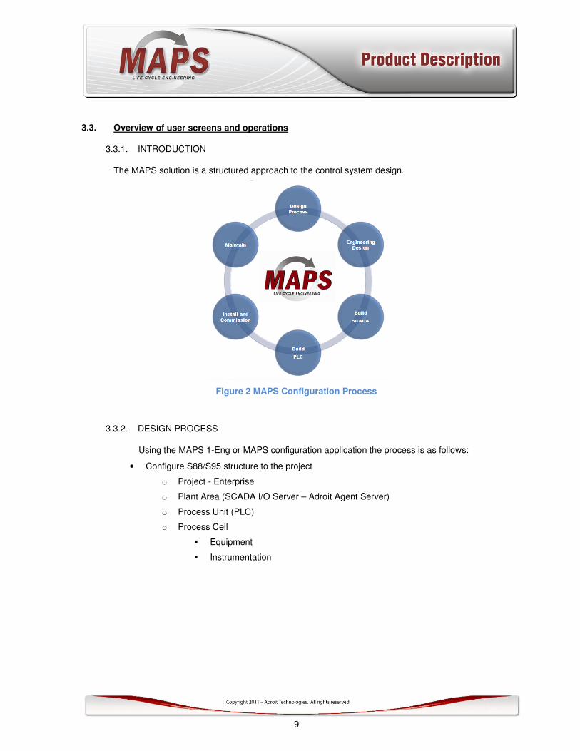
The MAPS solution is a structured approach to the control system design.
Figure 2 MAPS Configuration Process
3.3.2. DESIGN PROCESS
Using the MAPS 1-Eng or MAPS configuration application the process is as follows:
• Configure S88/S95 structure to the project
o Project - Enterprise
o Plant Area (SCADA I/O Server – Adroit Agent Server)
o Process Unit (PLC)
o Process Cell
� Equipment
� Instrumentation

10
Figure 3 - Project Physical Model
Each piece of equipment and instrumentation needs to be associated with a standard
available function block and an associated SCADA graphic.

11
3.3.3. BUILD THE SCADA
The SCADA screens are generated along with an overall navigation structure. All graphic objects are placed
on the associated Process Unit screen.
Figure 4 Configuring the SCADA environment
The user needs to then use the SCADA design environment to re-arrange the objects into the
process/operator view and add the static graphics. As well as add in any other SCADA functionality not
covered within MAPS.

12
Figure 5 Basic objects on screen in the Operator View
Figure 6 Completed SCADA screen
13
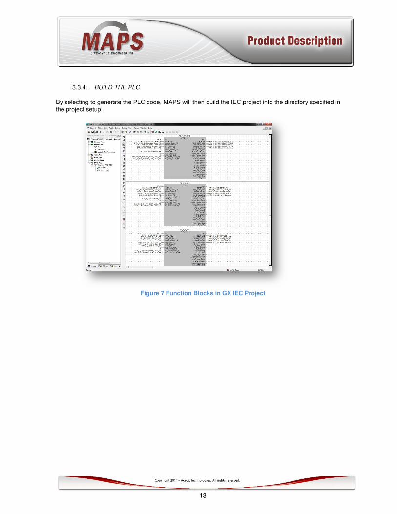
3.3.4. BUILD THE PLC
By selecting to generate the PLC code, MAPS will then build the IEC project into the directory specified in
the project setup.
Figure 7 Function Blocks in GX IEC Project

14
3.4. Features and benefits of MAPS
3.4.1. STANDARDS APPROACH TO PROJECTS
Based on ISA S88/S95 standards and using the pre-defined IEC Function Blocks and associated graphics
will deliver great value in the testing and commissioning phases of a project.
Function Blocks available in MAPS
• Digital Valve – Single Solenoid - Double Sensors
• Digital Valve – Double Solenoid – Double Sensors
• Control Valve (FCV)
• Digital Input (DI)
o Advanced with conditioning
o Basic with no conditioning
• Vessel Level
o Advanced with Analogue and 4 discrete levels
o Standard with Analogue only
o Basic with 2 discrete levels
• Digital Output (DO)
o Advanced
o Standard
o Basic
• Analogue In (AI)
o Advanced
o Standard
o Basic
• Analogue Out (AO)
o Advanced
o Standard
o Basic
• PID Control
o Advanced
o Standard
• Direct on line starter (DOL)
o Advanced
o Standard
o Basic
• DOL forward and reverse
• DOL 2 speed
• Variable Speed Drive (VSD)
• Intelligent VSD (bus based)
All these blocks have been QA tested and proven in the field offering confidence when commissioning and
operating the plant as the control engineers need only concern themselves with physical I/O and the
associated plant control program when fault finding.

15
3.4.2. STANDARD, SETUP AND DIAGNOSTIC FACEPLATES
Each object used in MAPS gives high value faceplates for setup, diagnostics and management. These are
accessed from the SCADA operator view by simply clicking on the graphic object.
Although different for the type and complexity of the Function Block chosen the common navigation will allow
both technicians and operators to understand better what is happening on the control system. Most
faceplates allow access to a filtered alarm and events screen, a trend screen specific to the FB. Apart from a
view of the various interlocks that are used the maintenance staff can select the Maintenance mode that
allows personnel to use the SCADA as a tool to stop/start, open/close etc. The second configuration screen
that can be accessed gives useful diagnostic and where built-in simulation capability for easy testing of the
solution.
Figure 8 Typical Standard Faceplates for an Advanced DOL

16
3.4.3. SINGLE POINT OF CONFIGURATION
The MAPS solution is a structured single point of configuration. Using the MAPS 1-Eng Designer allows for a
rapid building of your Engineering Design, SCADA and PLC project, using Excel as your tool. The finer
details can be done within the MAPS Designer including the final building of the SCADA graphics.
Figure 9 MAPS Design Environment
3.4.4. WORLD-CLASS SCADA
MAPS uses the Adroit SCADA environment as it’s underlying architecture.
This world-class client-server application offers a proven (over 15000 seats), fully scalable and open
architecture SCADA solution.
USER INTERFACE
Users have access to a world-class .NET based graphical user environment to build the rest of the project.
There is a Design and a Runtime (Operator) application.
In summary the Smart-Client Designer offers the following features:
• .NET familiar Design environment
• Windows forms based application
• Support for Adroit vectors and the ability to import XAML from other applications
• Controls for Adroit – trend, alarm, event windows
• Microsoft .NET scripting support in the UI (C# and VB.NET)- Integrated with Visual Studio for de-
bugging
• Support for using standard Windows and ActiveX controls
• The Smart-Client “spider engine” allows for configuration of complex behaviours. The ability to drive
any property of any control with real-time data.
• Many static shapes for using with the UI
• Internet enabled

17
SERVER APPLICATION (Adroit Agent Server):
The Adroit Server application is the most object-oriented of any SCADA on the market today. The core
Server uses plug-in objects (Adroit Agents) that offer different functions and capability. For example the
Scanning object handles all the real-time scanning functions for the Server. The Analogue Agent is used to
then scan variables from the field (PLC/RTU) and offers specific functionality around the Analogue; scaling,
alarming etc. The Server application also supports redundancy through the Adroit Active Clustering
technology.
There are over 50 Agents that perform different tasks and functions, some of the Agents are:
Standard
Analogue, Integer, Digital, String, String List, Date, Text, Expression, Timer
Figure 70 Adroit Analogue Agent
18
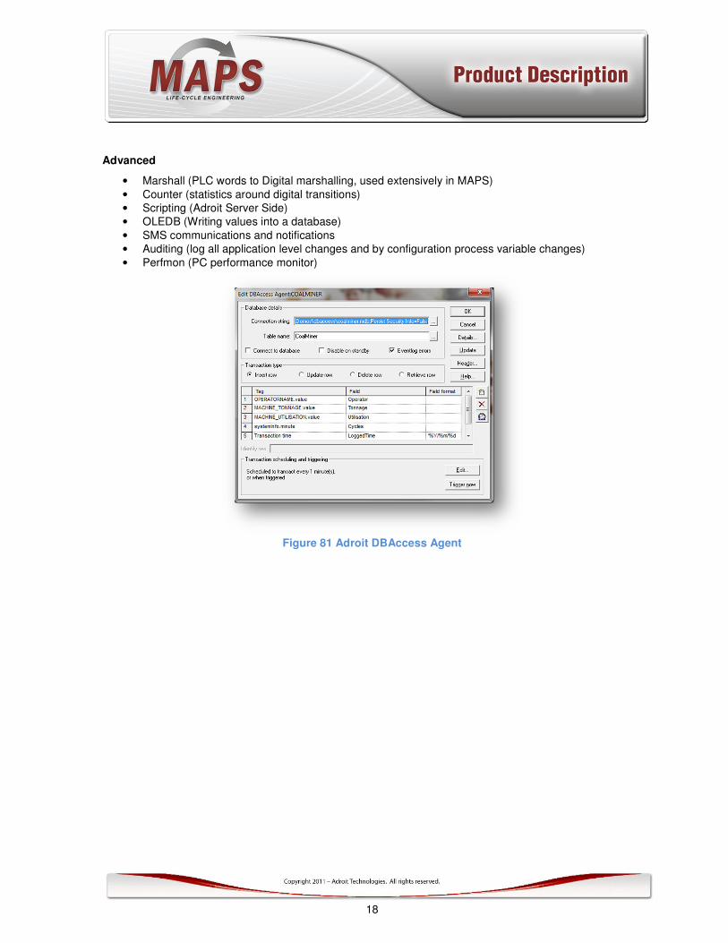
Advanced
• Marshall (PLC words to Digital marshalling, used extensively in MAPS)
• Counter (statistics around digital transitions)
• Scripting (Adroit Server Side)
• OLEDB (Writing values into a database)
• SMS communications and notifications
• Auditing (log all application level changes and by configuration process variable changes)
• Perfmon (PC performance monitor)
Figure 81 Adroit DBAccess Agent

19
Advanced Performance Management Agents (MES/MIS)
• OEE (overall equipment effectiveness – licensed)
• SNMP (licensed)
• Alarm Management (licensed)
• Maximum Demand Agent (Energy Management)
Figure 92 Adroit Maximum Demand Agent
20
3.4.5. ON-GOING LIFE-CYCLE MANAGEMENT
The MAPS solution offers customers the capability of on-going management of their PLC/SCADA solution.
Whether tags are changed in the PLC or the MAPS management environment the project ensures that items
are synchronized between the two programming environments.
3.4.6. AUTOMATICALLY GENERATED PLC AND SCADA PROJECTS
The wizard approach to projects using MAPS will see all users benefit greatly in time spent on design and
configuration. With reductions between 30% and 50% with higher quality more standardized approach. The
fact that projects all have the same structure means that on-going maintenance is made really easy.
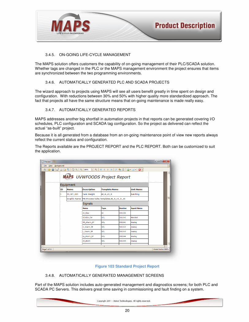
3.4.7. AUTOMATICALLY GENERATED REPORTS
MAPS addresses another big shortfall in automation projects in that reports can be generated covering I/O
schedules, PLC configuration and SCADA tag configuration. So the project as delivered can reflect the
actual “as-built” project.
Because it is all generated from a database from an on-going maintenance point of view new reports always
reflect the current status and configuration.
The Reports available are the PROJECT REPORT and the PLC REPORT. Both can be customized to suit
the application.
Figure 103 Standard Project Report
3.4.8. AUTOMATICALLY GENERATED MANAGEMENT SCREENS
Part of the MAPS solution includes auto-generated management and diagnostics screens; for both PLC and
SCADA PC Servers. This delivers great time saving in commissioning and fault finding on a system.
21
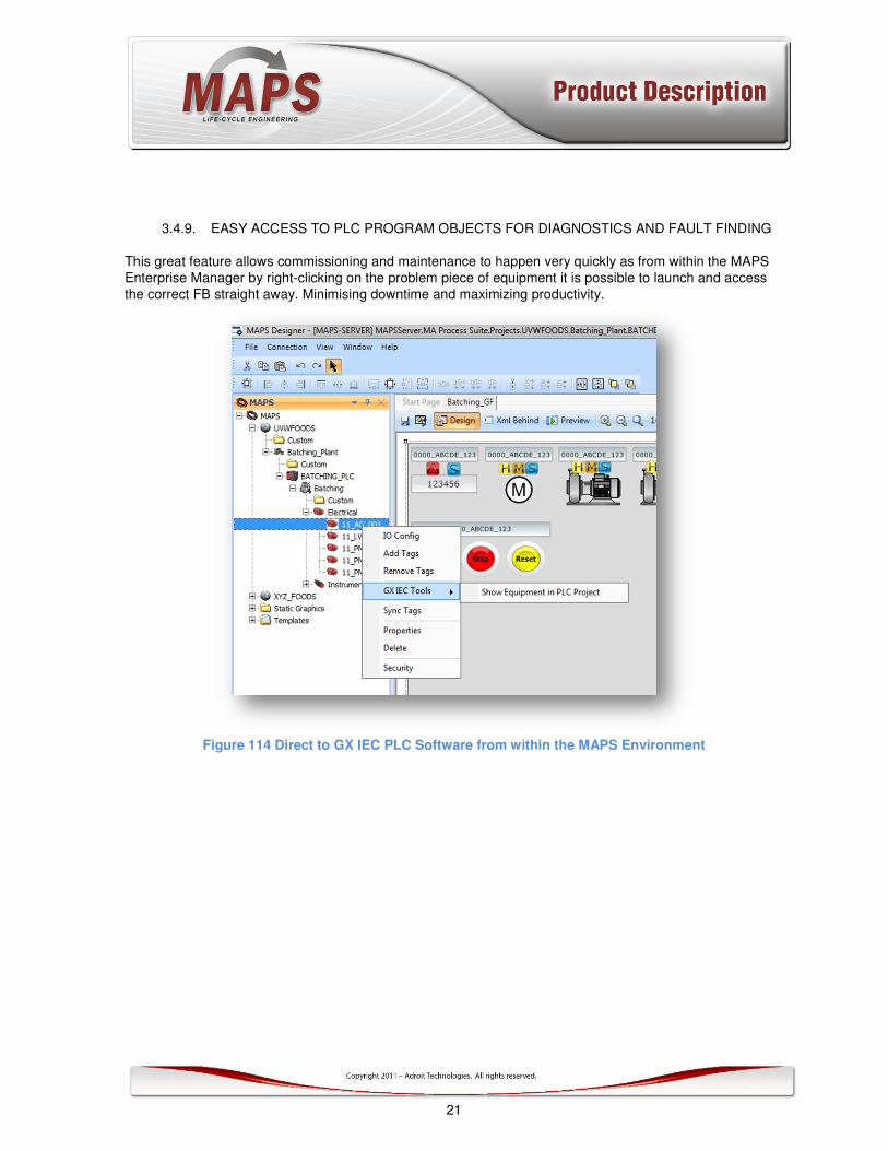
3.4.9. EASY ACCESS TO PLC PROGRAM OBJECTS FOR DIAGNOSTICS AND FAULT FINDING
This great feature allows commissioning and maintenance to happen very quickly as from within the MAPS
Enterprise Manager by right-clicking on the problem piece of equipment it is possible to launch and access
the correct FB straight away. Minimising downtime and maximizing productivity.
Figure 114 Direct to GX IEC PLC Software from within the MAPS Environment

22
3.4.10. EASY ACCESS TO PLC DIAGNOSTICS
This feature allows easy access to the important PLC diagnostics from within the MAPS Enterprise Manager.
Figure 15 Access to PLC Diagnostics

23
3.5. Industries and applications
MAPS can be used in almost any of the following industries:
General Manufacturing Mining
Petrochemical Mineral Processing
Pulp and Paper Automotive
Food and Beverage Pharmaceutical and Medical
Energy Management Building Management
Water Treatment/Distribution Cement
Agriculture Nuclear
Food and Beverage Power Utilities
Telecommunications
There are a limitless number of applications that are suited to Adroit. Various application stories are available from the Adroit web page (http://www.adroit.co.za).