marc jeroense, abb, icc, march 23, 2010 education … · education session hvdc, embrace or reject?...
TRANSCRIPT

© ABB Group September 08 Slide 1
Education SessionHVDC, embrace or reject?
Marc Jeroense, ABB, ICC, March 23, 2010

© ABB Group September 08 | Slide 2
The journey
From a global perspective to the smallest entities

© ABB Group September 08 | Slide 3
Content
Why HVDC? Types of cables
MI Extruded Other
Electric field AC DC Space charge – what is it? Space charge – how do you measure it?
Accessories Joints (flexible, stiff) Termination
Qualification Recommendations (CIGRÉ) Type test Pre-qualification test

© ABB Group September 08 | Slide 4
Why HVDC?
Traditional applications (Classic and HVDC Light)
Sub sea transmission
Long distance transmission
Asynchronous interconnections
New applications (HVDC Light)
…
…
… (next slide)
Estonia
Finland

© ABB Group September 08 | Slide 5
Why HVDC?New HVDC applications
Underground transmission
Oil & Gas
Offshore Wind power

© ABB Group September 08 | Slide 6
Why HVDC?The issue of renewables
Increase the use of renewables, with for instance
Hydro power
Solar power

© ABB Group September 08 | Slide 7
Why HVDC?The issue of renewables
There is a problem though…

© ABB Group September 08 | Slide 8
Why HVDC?The issue of renewables
The renewable energy sources tend to be located far away from the areas of consumption
Losses increase as per distance!

© ABB Group September 08 | Slide 9
120 GW50
GW
50 GW
300 GW
Totally about 500 GWTransmission 2000 – 3000 km
Why HVDC? Remote hydro power resources

© ABB Group September 08 | Slide 10
Energy from deserts

© ABB Group September 08 | Slide 11
Why HVDC?
Why not HVAC?
Charging currents (cable acts as a capacitance)

© ABB Group September 08 | Slide 12
Why HVDC?
current
Uac
Maximum length of ac cables The longer the cable, the more current the cable asks for itself. At a certain length the this cable current heats the cable to its maximum temperature At 10-20% reduction of current, economicaly uninteresting critical length
load

© ABB Group September 08 | Slide 13
No maximum length for DC cable
Udc load
No charging current! No critical length!

© ABB Group September 08 | Slide 14
… and lower losses
Ohmic Losses in conductor Induced losses in conductor Induced losses in sheath Induced losses in armouring Induced losses in neighbouring cables Cable current due to length
AC cables Ohmic Losses in conductor
-
-
-
-
-
DC cables
AC DC0
5
10
15
20
25
30
ac dc
Mea
n el
ectri
c fie
ld [k
V/m
m]

© ABB Group September 08 | Slide 15
Types of HVDC cables
MI – Mass Impregnated paper insulation Maximum conductor temperature
55°C
Maximum voltage commercially available 500 kV
Extruded, like HVDC Light cables Maximum conductor temperature at
least 70°C
Maximum voltage commercially available 320 kV
Less usual: oil pressurised cables for HVDC

© ABB Group September 08 | Slide 16
MI cable development history

© ABB Group September 08 | Slide 17
MI Cable
Conductor
Lead sheathFluidPaper
HVDC Mass Impregnated Non-Draining cable

© ABB Group September 08 | Slide 18
MI CablePartial Discharges at DC - one void
( )αττ −=
−≈
111
minmin UU
UUUn s
r
s
The repetition rate n of the void depends on the:
• asymptotic voltage across Us the void
• time constant τ
• minimum breakdown voltage Umin
• residual voltage Ur (α = Ur / Umin)
Volta
ge U
cac
ross
the
void
Time
Void

© ABB Group September 08 | Slide 19
MI CablePartial Discharges at DC - many voids
Voids in
• butt-gaps
• between paper layers
• inside paper
Void distribution: Φr
( )ατ −≈
11
minUUn s
( ) rr rr
r
r UEn φ
ατ∑ −≈
11
min,
One void
Many voids:
Cable
© ABB Group September 08 | Slide 20
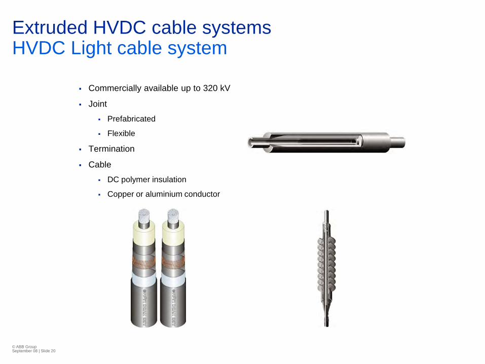
Extruded HVDC cable systemsHVDC Light cable system
Commercially available up to 320 kV
Joint
Prefabricated
Flexible
Termination
Cable
DC polymer insulation
Copper or aluminium conductor

© ABB Group September 08 | Slide 21
Extruded HVDC cable systemWhat power can it transmit?

© ABB Group September 08 | Slide 22
Extruded HVDC cable systemWhat power can it transmit?
Aluminium
0200400600800
100012001400
0 500 1000 1500 2000 2500
Conductor Area [mm2]
Tran
smis
sion
Cap
acity
[M
W]
80 kV
150 kV
320 kV
Copper
0200400600800
100012001400
0 500 1000 1500 2000 2500
Conductor Area [mm2]
Tran
smis
sion
Cap
acity
[M
W]
320 kV
150 kV
80 kV
Transporting power depends on Voltage
Conductor area
Installation conditions

© ABB Group September 08 | Slide 23
Extruded HVDC cable system Qualification
Extruded HVDC cable systems becoming a mature product
More than 20 type tests and several long term tests have qualified the cable system on the 80, 150 and 320 kV level
By the end of 2009 a total of 1903 km HVDC Light cable is in service
0
200
400
600
800
1000
1200
1996 1998 2000 2002 2004 2006 2008 2010
Voltage [kV]Power [MW]
0200400600800
100012001400160018002000
1998 1999 2002 2004 2006 2009
Kilo
met
ers
in s
ervi
ce

© ABB Group September 08 | Slide 24
Extruded HVDC cable system Applications
Pho
to: D
ON
G E
nerg
yP
hoto
: DO
NG
Ene
rgy
Oil & gas On/Offshore Wind
Bulk transport – sea Bulk transport – land

© ABB Group September 08 | Slide 25
Extruded HVDC cable system Experience and projects
Oil and gas
Troll-A 284 km
On/Offshore Wind
BorWin 1 421 km
GotLight 140 km
Bulk transport sea
Estlink 212 km
Cross Sound 85 km
Transbay xx km
Hokkaido Island and Honshu Main Land. 45 km
EWIP 500 km
Bulk transport land
MurrayLink 360 km
DirectLink 390 km
Pho
to: D
ON
G E
nerg
yP
hoto
: DO
NG
Ene
rgy

© ABB Group September 08 | Slide 26
Electric fieldAC
The field distibution depends solely on the permittivity and the geometry of the cable
Elec
tric
Fiel
d

© ABB Group September 08 | Slide 27
Electric fieldDC
”What is the electric field?”
What do you mean?
Capacitive field t=0
Intermediate (transient) field 0<t<∞
Resistive field t=∞
Switching surge fields

© ABB Group September 08 | Slide 28
Electric fieldResistive
AC
general Stable DC
( )( ) ( ) 0, 0 =
∇∂∂
⋅∇+∇⋅∇ Ut
UET rεεσ
Stable DC fields Time-dependent fields
Changing voltage
Changing temperature
constant=ε
=
Field Electric,Τemperatur
fσe

© ABB Group September 08 | Slide 29
Electric fieldResistive
( ) ( )ET γασσ expexp0=
Tem
pera
ture
RadiusTe
mpe
ratu
re
Radius
Tem
pera
ture
Radius
Elec
tric
Fiel
d
Radius
Elec
tric
Fiel
dEl
ectri
c Fi
eld
Radius
σ

© ABB Group September 08 | Slide 30
Electric fieldIntermediate
From capacitive to resistive distribution (loaded cable in example)
Elec
tric
Fiel
d
Radius
Elec
tric
Fiel
d

© ABB Group September 08 | Slide 31
Electric fieldIntermediate Consider a 3-layer Maxwell
capacitor
U
a b c
σε
τ =
τa = 0.5τb =0.1τc

© ABB Group September 08 | Slide 32
Electric fieldResisive and surge
20 25 30 35 40 4519
20
21
22
23
24
25
26
27
28
29Elektrisk fältstyrka Baltic Cable
Radie från ledarcentrum [mm]E
[kv/
mm
]
varm
kall
20 25 30 35 40 45-80
-60
-40
-20
0
20
40Elektrisk fältstyrka Baltic Cable
Radie från ledarcentrum [mm]
E [k
v/m
m]
varmkall
varm stöt

© ABB Group September 08 | Slide 33
Electric fieldSpace charge
Elec
tric
field
0 kV
σ1, ε1

© ABB Group September 08 | Slide 34
Electric fieldSpace charge
Elec
tric
field
+++++++
-------
Udc
σ1, ε1

© ABB Group September 08 | Slide 35
Electric fieldSpace charge
Elec
tric
field
-------
Udc
+++++++
σ1, ε1 σ2, ε2+++++++
σ1>σ2

© ABB Group September 08 | Slide 36
Electric fieldSpace charge
Elec
tric
field
-------
Udc
+++++++
σ1, ε1 σ2, ε2 σ1<σ2-------
© ABB Group September 08 | Slide 37
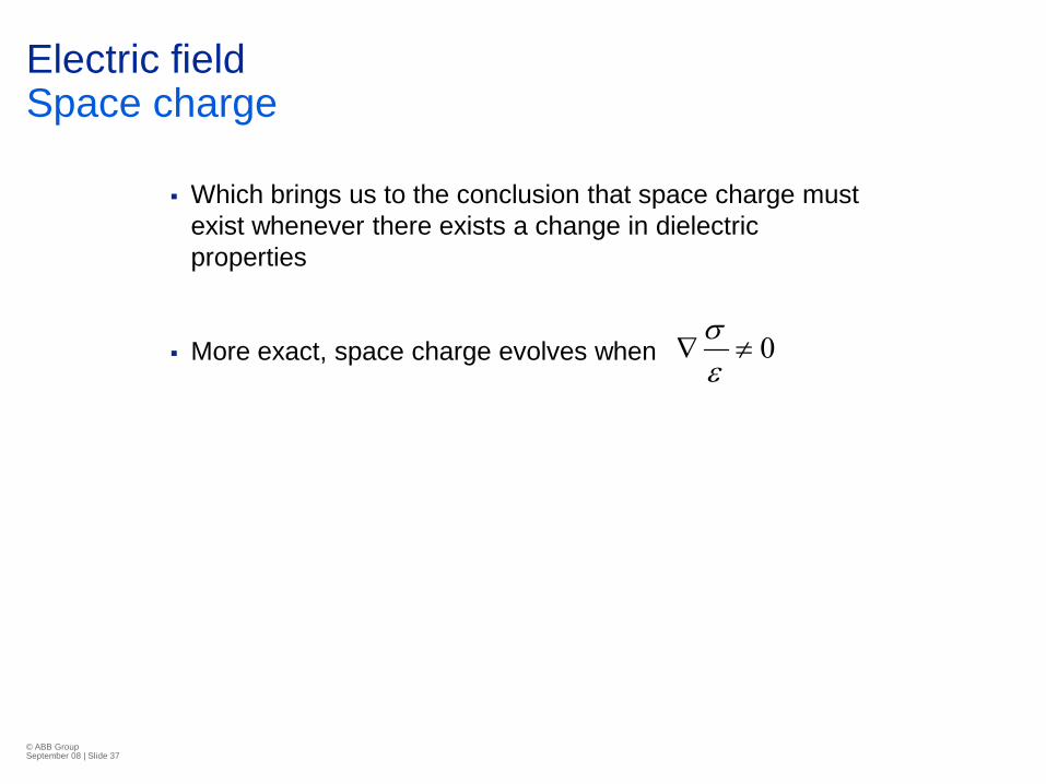
Electric fieldSpace charge
Which brings us to the conclusion that space charge must exist whenever there exists a change in dielectric properties
More exact, space charge evolves when 0≠∇εσ

© ABB Group September 08 | Slide 38
Electric fieldSpace charge
Back to our loaded dc cable with a temperature drop across the inuslation As the conductovity is temperature
dependent
And as the temperature is not constant along te radius
This must mean that
Which in its turn means that we have space charge inside the cable
Stable DC
0≠∇εσ

© ABB Group September 08 | Slide 39
Electric fieldSpace charge
How do you measure it?
-------
Udc
+++++++
σ1, ε1
σ2, ε2
+++++++
pulse
Amp
Acoustic sensor
t
© ABB Group September 08 | Slide 40
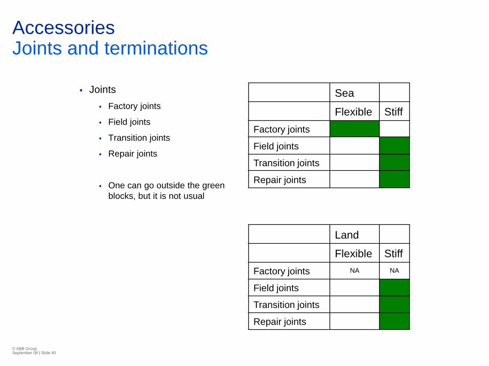
Accessories Joints and terminations
Joints Factory joints
Field joints
Transition joints
Repair joints
One can go outside the green blocks, but it is not usual
Sea
Flexible StiffFactory joints
Field joints
Transition joints
Repair joints
Land
Flexible StiffFactory joints NA NA
Field joints
Transition joints
Repair joints

© ABB Group September 08 | Slide 41
Accessories (HVDC Light example) Joints and terminations80 kV 150 kV 320 kV
150 kV80 kV320 kV

© ABB Group September 08 | Slide 42
AccessoriesCalculations
The basic theory as explained for the cable previously holds for the more complex cases like terminations
…and joints
© ABB Group September 08 | Slide 43
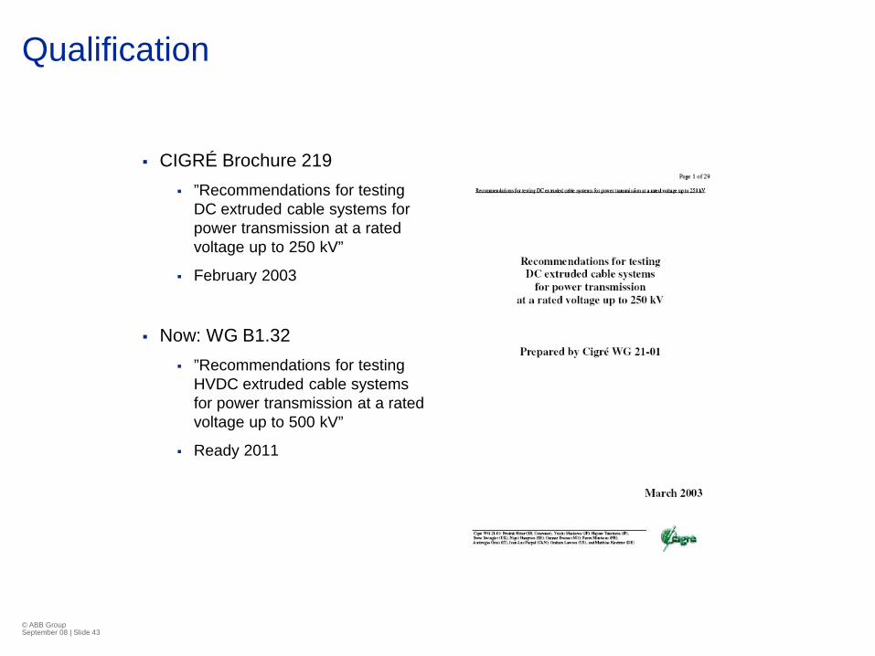
Qualification
CIGRÉ Brochure 219 ”Recommendations for testing
DC extruded cable systems for power transmission at a rated voltage up to 250 kV”
February 2003
Now: WG B1.32 ”Recommendations for testing
HVDC extruded cable systems for power transmission at a rated voltage up to 500 kV”
Ready 2011

© ABB Group September 08 | Slide 44
QualificationCIGRE
A document for paper insulated HVDC cables
A document for extruded cable systems
© ABB Group September 08 | Slide 45
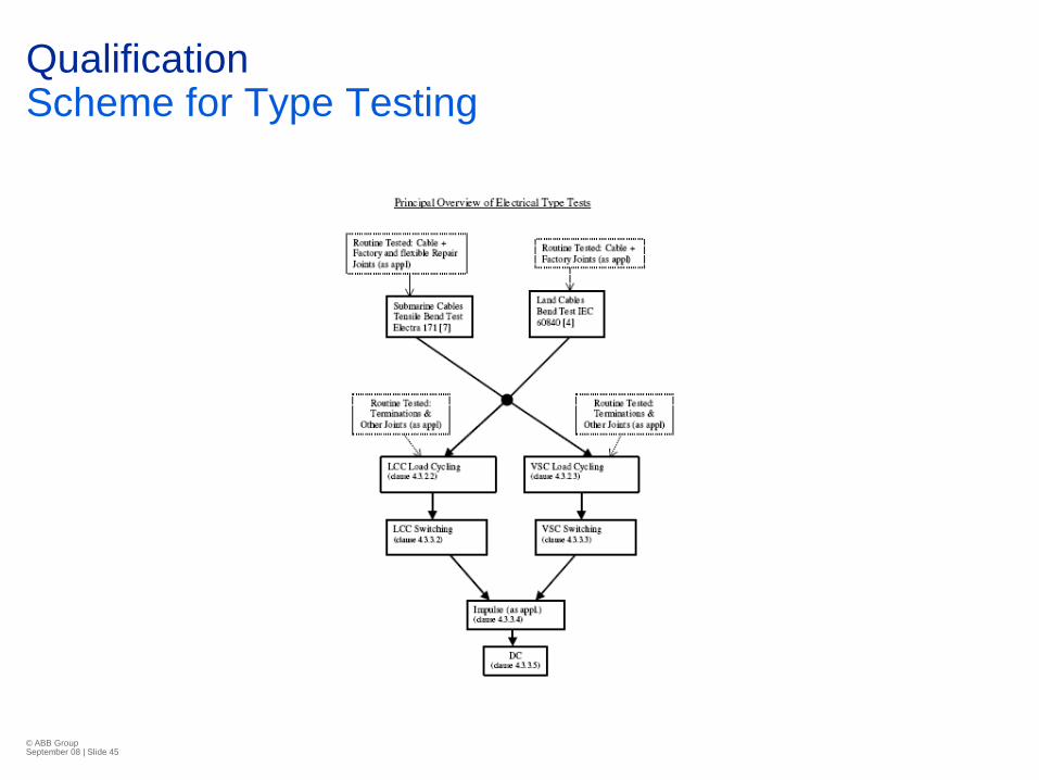
QualificationScheme for Type Testing

© ABB Group September 08 | Slide 46
QualificationScheme for Type Testing

© ABB Group September 08 | Slide 47
QualificationType Testing
Load Cycle TestCurrent I
Voltage
Voltage U
Current ITime
0
0
-KU0
+KU0
8/16 24/24
U

© ABB Group September 08 | Slide 48
QualificationType Testing
Superimposed Switching Surge Withstand Test
”4x10”
Superimposed Lightning Surge Withstand test only if the terminaton is located – unprotected – outisde
LCCVSC

© ABB Group September 08 | Slide 49
Long TermTesting

© ABB Group September 08 | Slide 50
… a last thingI promised you
From a global perspective to the smallest entities

© ABB Group September 08 | Slide 51
Leakage current in the insulation
Current density
Comes down to the number of charges per unit time through a unit surface
The higher the insulation resistance, the lower the leakage current density

© ABB Group September 08 | Slide 52
Leakage current in the insulation
High resistance
Low current density
Low resistance
High current density

© ABB Group September 08 | Slide 53
Leakage current in the insulation
Smallest polymer entity in the insulation spherulite
Cable insulation
Spherulite
© ABB Group September 08 | Slide 54
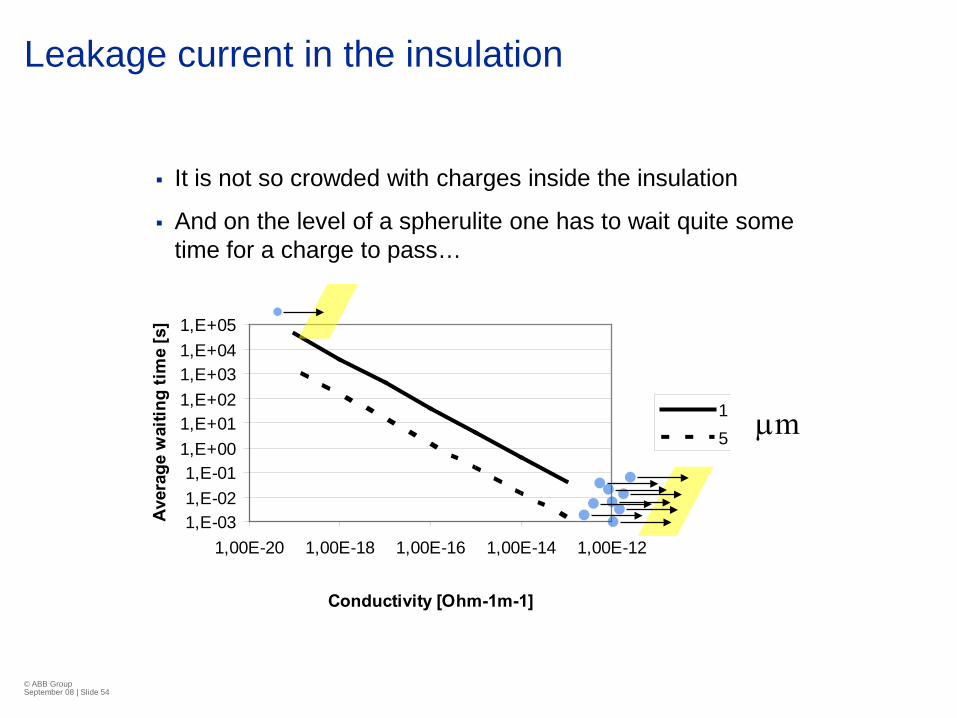
Leakage current in the insulation
It is not so crowded with charges inside the insulation
And on the level of a spherulite one has to wait quite some time for a charge to pass…
1,E-031,E-021,E-01
1,E+001,E+011,E+021,E+031,E+041,E+05
1,00E-20 1,00E-18 1,00E-16 1,00E-14 1,00E-12
Conductivity [Ohm-1m-1]
Aver
age
wai
ting
time
[s]
1 mm5 mmµm

© ABB Group September 08 | Slide 55
The journey
Now we at last has arrived at the level of the charges; the electron for instance.

© ABB Group September 08 | Slide 56
Now back to reality…
Questions?

© ABB Group September 08 | Slide 57
Thank you for your attention!

© ABB Group September 08 | Slide 58
The Principal Physics
Voltage U
Current I
Time
Temperature Increase
Pressure Increase
Fluid Flow
Temperature Decrease
Partial Backflow of Fluid
Pressure Decrease
Void Creation
Positive Expansion Coefficient
Low Viscosity
High Viscosity