marcom professional software - judge toolmarcom professional© software bedienungsanleitung...
TRANSCRIPT

MarCom Professional©
Software
Bedienungsanleitung
Operating instructions
3722558
Version 5.2
0317
��
��
Mahr GmbH Standort Esslingen
Reutlinger Str. 48, 73728 EsslingenTel.: +49 711 9312 600, Fax: +49 711 9312 756
[email protected], www.mahr.com
2 Mahr GmbH • MarCom Professional 5.2© Software
��
Contents
Introduction ......................................................................................................................3
Installation ......................................................................................................................3
Start program ......................................................................................................................4
Menu bar and configuration .......................................................................................................5
1. Program ......................................................................................................................5 1.1 Close window .................................................................................................................5 1.2 Exit ......................................................................................................................5
2. Measuring Instruments ...............................................................................................6 2.1 Reset Measurement Cycle .............................................................................................6 2.2 Previous ......................................................................................................................6 2.3 Next ......................................................................................................................6 2.4 Edit ......................................................................................................................6 2.5 Request Value ................................................................................................................6 2.6 Add a RF Device ............................................................................................................7 2.7 Delete a RF Device ........................................................................................................7 2.8 Delete All RF Devices ....................................................................................................7 2.9 Refresh ......................................................................................................................7
3. Settings ......................................................................................................................8 3.1 Password protection ......................................................................................................8 3.2 Load ......................................................................................................................8 3.3 Save ......................................................................................................................9 3.4 Save as ......................................................................................................................9 3.5 Measuring Station No. ...................................................................................................9 3.6 RF ......................................................................................................................9 3.7 COM ....................................................................................................................10 3.8 File ....................................................................................................................10 3.9 Virtual Interface Box ....................................................................................................10 3.10 Autostart ....................................................................................................................11 3.11 Languages ...................................................................................................................11 3.12 Beep ....................................................................................................................11
4.0 Information (?) ............................................................................................................12 4.1 Info ....................................................................................................................12 4.2 Mahr Homepage ..........................................................................................................12
5. Parameterize Measuring Instruments ......................................................................13 5.1 MC-I Switch ..................................................................................................................13 5.2 Measuring Instrument ..................................................................................................14
6. Connecting RF Devices .............................................................................................21 6.1 i-Stick - Integrated Wireless .........................................................................................21 6.2 e-Stick / FM2 - External Modules .................................................................................25
7. Virtual Interface Box ..................................................................................................28
8. Overview of the Status and Configuration Windows ..............................................33
9. Implementing a Remote Control ...............................................................................34
10. RS232 Settings on a Measuring Instruments ..........................................................35
11. Technical Data ............................................................................................................36 11.1 e-Modules ....................................................................................................................36 11.2 e-Stick Receiver ...........................................................................................................36 11.1 FM2-Modules ...............................................................................................................36 11.2 FM2-Receiver ...............................................................................................................36

3Mahr GmbH • MarCom Professional 5.2© Software
��
MarCom Professional 5.2 ©
Introduction
With the MarCom Software you can transfer your measured values into a text file, into Microsoft Office Excel® or via a keyboard code into any application, all you need is a Mahr measuring instrument connected via a USB port and a Mahr USB data cable or with the integrated wireless receiver (i-Stick). In addition to a USB port it is also possible to use a serial COM interface with the suitable data cable for data transmission.Additionally the MarCom Professional Software is enabling you to transfer your measurement data to a text file, as key code, into an MS Excel spreadsheet or via the virtual interface box to another SPC-/CAQ-software. With the MarCom Professional Software you can operate up to 127 measuring instruments (subtract the amount of hubs being used) via the USB hubs and transfer the measured values from individual measuring instruments to the chosen transfer file.Therefore you can easily centralize the multiple measuring instruments to just one measurement station. With the aid of a USB foot switch (optional) you can also transfer your measured values from each individual measuring instrument to a text file, blank sheets, in separate Microsoft Office Excel® columns or to a CAQ software.
Note: When several USB hubs (e.g. for cascading) are connected together these must be operated in conjunction with an external power supply.
Please read the following operating instructions carefully so that you can become quickly accustomed to the MarCom Software.
Installation
In order to start the installation of the MarCom Software, please execute the Setup-MarCom.exe file and follow the instructions. Once successfully installed you may plug in the USB cable or the receiver (i-Stick/e-Stick/FM2) and continue with the installation of the driver. If you wish to connect multiple USB data cables we recommend that you install the cable and driver successively.
Note: Once the wireless receiver (i-Stick/e-Stick) has been installed, up to 8 wireless measuring instruments can be used. Should you require further 8 wireless measuring instruments a second i-Stick should be plugged into a free USB interface. A total of maximum 4 i-Stick/1 e-Stick wireless receiver with 32/8 measuring instruments can be connected simultaneously.
Minimum system requirements:
• MS Windows 7, 8, 10• One free USB-interface 2.0 or higher• Up to 500 MB of available hard disk space• Recommended: MS-Excel 97 or higher
4 Mahr GmbH • MarCom Professional 5.2© Software
��
Start program
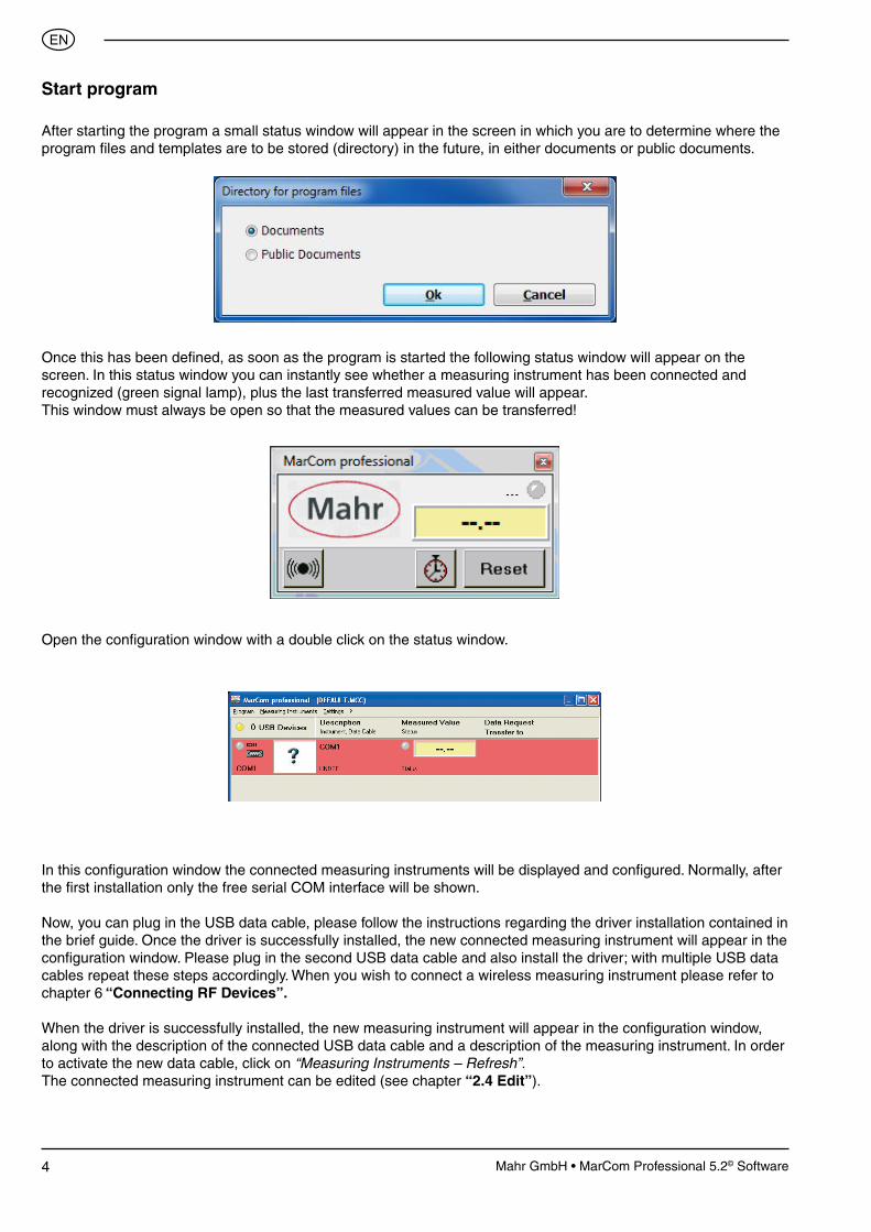
After starting the program a small status window will appear in the screen in which you are to determine where the program files and templates are to be stored (directory) in the future, in either documents or public documents.
Once this has been defined, as soon as the program is started the following status window will appear on the screen. In this status window you can instantly see whether a measuring instrument has been connected and recognized (green signal lamp), plus the last transferred measured value will appear.This window must always be open so that the measured values can be transferred!
In this configuration window the connected measuring instruments will be displayed and configured. Normally, after the first installation only the free serial COM interface will be shown.
Now, you can plug in the USB data cable, please follow the instructions regarding the driver installation contained in the brief guide. Once the driver is successfully installed, the new connected measuring instrument will appear in the configuration window. Please plug in the second USB data cable and also install the driver; with multiple USB data cables repeat these steps accordingly. When you wish to connect a wireless measuring instrument please refer to chapter 6 “Connecting RF Devices”.
When the driver is successfully installed, the new measuring instrument will appear in the configuration window, along with the description of the connected USB data cable and a description of the measuring instrument. In order to activate the new data cable, click on “Measuring Instruments – Refresh”.The connected measuring instrument can be edited (see chapter “2.4 Edit”).
Open the configuration window with a double click on the status window.

5Mahr GmbH • MarCom Professional 5.2© Software
��
Menu bar and configuration
1. Program
1.1 Close window
With this menu you can close the configuration window; alternatively, you can click on the cross with the red background in the top right corner of the configuration window. Even when the configuration window is closed the status window is still open and it is still possible to transfer measured values. With a double click upon the status window the configuration window will reopen.
1.2 Exit
If you click on Exit the complete MarCom Program including the status window will be closed, no further measured values will be transferred. Alternatively you can click on the cross with the red background in the top right corner of the status window.

6 Mahr GmbH • MarCom Professional 5.2© Software
��
2. Measuring Instruments
2.1 Reset Measurement Cycle
In the parameter window the MC-I data cable (e.g. foot switch), or a measuring instrument; the defined measuring cycle will be reset to zero. See sections “5.1 MC-I Switch” and “5.2 Measuring Instrument”.
Alternatively, the measuring cycle can also be reset clicking the Reset button in the status window.
2.2 Previous The red field highlighted in the configuration window will move to the preceding measuring instrument e.g.
from USB2 to USB1. The highlighted measuring instrument can then be edited. Tip: You can also select a measuring instrument to be edited by clicking upon it.
2.3 Next
The field highlighted in red in the configuration window will return to the following measuring instrument e.g. from USB 2 to USB 3. The highlighted measuring instrument can then be edited.
Tip: You can also click upon a measuring instrument to edit it.
2.4 Edit
With Edit the parameter window of the aforementioned red highlighted measuring instrument will open. Here the settings for the connected measuring instrument can be made. See ”5. Parameterize Measuring Instruments”
Tip: The parameter window can also be opened with a double click on the image of the measuring instrument in the configuration window.
2.5 Request Value
For test purposes a measuring value from a measuring instrument can be requested.

7Mahr GmbH • MarCom Professional 5.2© Software
��
2.6 Add a RF Device
Add a new RF device to the MarCom Software. In the submenu there are 3 RF systems available.
i-Stick Integrated Wireless system based on ANT+ technology.
e-Stick A new series of external RF module units which are similar to FM2; however, with a new and compact USB
receiver which uses low Energy RF (wireless) technology.
FM2 An older range of external RF module unit, these can be connected via the cable interface.
For further detailed information regarding how to add an RF device, please refer to chapter “6 Connecting integrated wireless measuring instruments”.
2.7 Delete a RF Device
Connected RF devices can be deleted in the MarCom configuration. To reinstall an instrument in the MarCom Software, please refer to chapter “2.6 Add a RF device”.
2.8 Delete all RF Devices
All connected RF devices can be deleted in the MarCom configuration. To reinstall these instruments in the MarCom Software, please refer to chapter “2.6 Add a RF device”.
2.9 Refresh
The USB port will be examined for a detached or a newly connected cable, additionally the configuration window will return to the last saved version.
Attention: When the cable is either plugged in or out the configuration will automatically be refreshed! Amended settings and settings that have not been saved will be lost!

8 Mahr GmbH • MarCom Professional 5.2© Software
��
3. Settings
3.2 Load
Here the previously saved configuration settings can be reloaded.
3.1 Password Protection
Here you can determine a password for your MarCom configuration, thus protecting against unauthorized third-party access. Simply enter any desired password, repeat the process a second time, and subsequently activate the password protection by pressing Activate.
In order to revoke the password protection, enter the password and then press Abort. To reactivate a password simply enter any desired password, repeat the process a second time, subsequently activate the password protection with the Activate icon.
Attention: Please store your password carefully otherwise you cannot deactivate the password protection!
9Mahr GmbH • MarCom Professional 5.2© Software
��
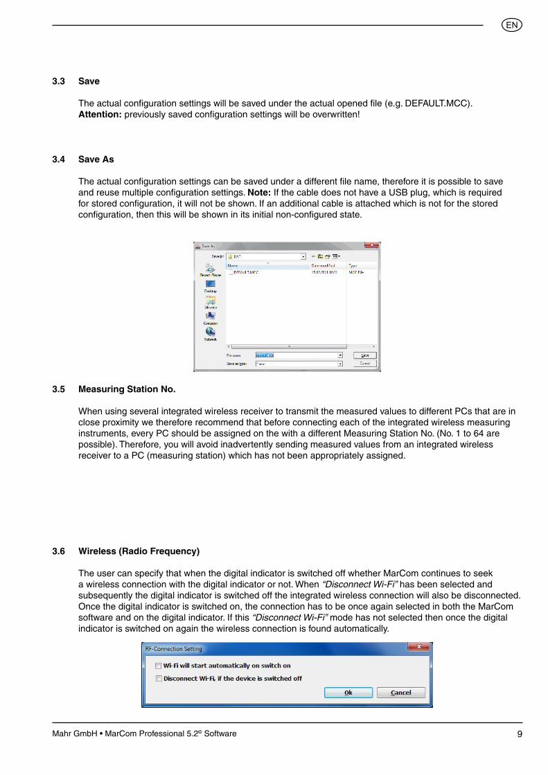
3.4 Save As
The actual configuration settings can be saved under a different file name, therefore it is possible to save and reuse multiple configuration settings. Note: If the cable does not have a USB plug, which is required for stored configuration, it will not be shown. If an additional cable is attached which is not for the stored configuration, then this will be shown in its initial non-configured state.
3.5 Measuring Station No.
When using several integrated wireless receiver to transmit the measured values to different PCs that are in close proximity we therefore recommend that before connecting each of the integrated wireless measuring instruments, every PC should be assigned on the with a different Measuring Station No. (No. 1 to 64 are possible). Therefore, you will avoid inadvertently sending measured values from an integrated wireless receiver to a PC (measuring station) which has not been appropriately assigned.
3.6 Wireless (Radio Frequency)
The user can specify that when the digital indicator is switched off whether MarCom continues to seek a wireless connection with the digital indicator or not. When “Disconnect Wi-Fi” has been selected and subsequently the digital indicator is switched off the integrated wireless connection will also be disconnected. Once the digital indicator is switched on, the connection has to be once again selected in both the MarCom software and on the digital indicator. If this “Disconnect Wi-Fi” mode has not selected then once the digital indicator is switched on again the wireless connection is found automatically.
3.3 Save
The actual configuration settings will be saved under the actual opened file (e.g. DEFAULT.MCC). Attention: previously saved configuration settings will be overwritten!
10 Mahr GmbH • MarCom Professional 5.2© Software
��
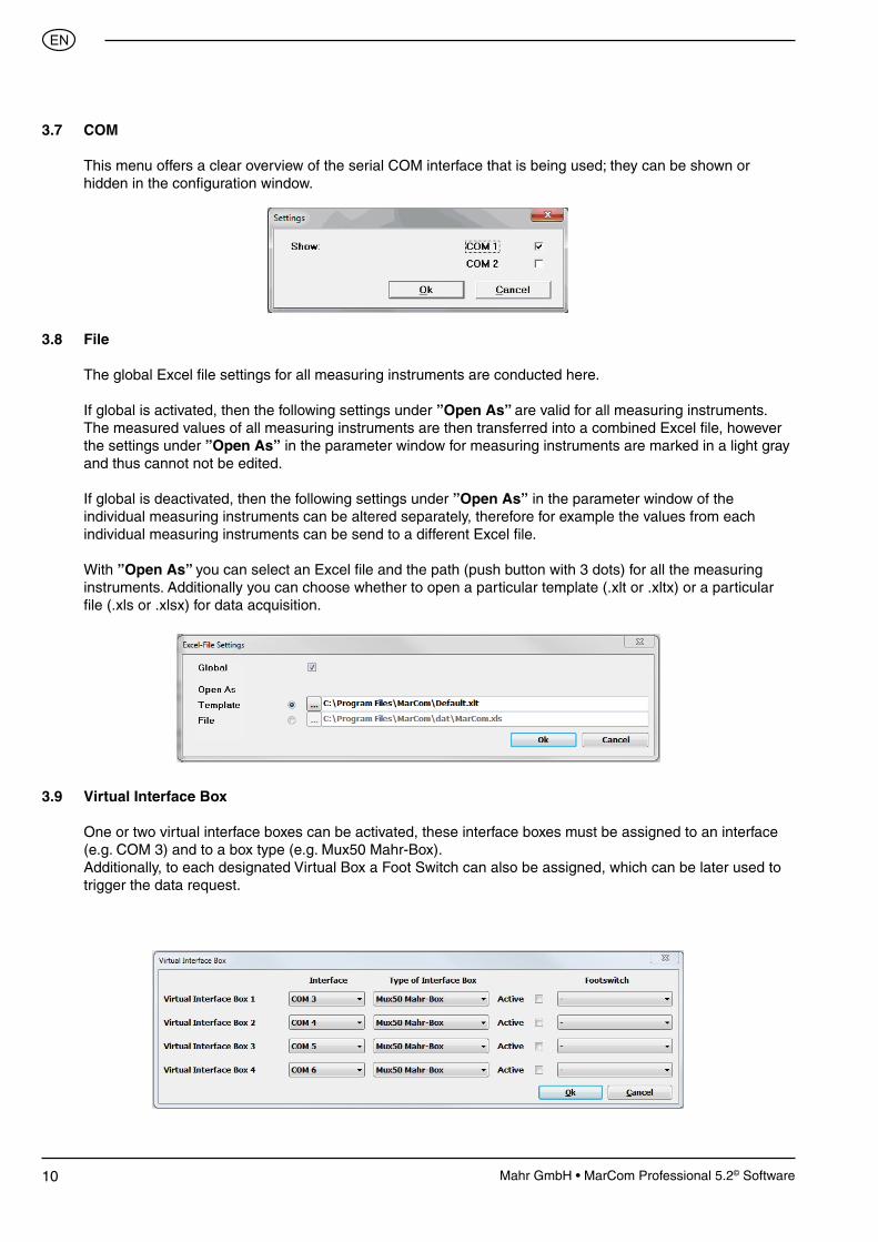
3.7 COM
This menu offers a clear overview of the serial COM interface that is being used; they can be shown or hidden in the configuration window.
3.8 File
The global Excel file settings for all measuring instruments are conducted here.
If global is activated, then the following settings under ”Open As” are valid for all measuring instruments. The measured values of all measuring instruments are then transferred into a combined Excel file, however the settings under ”Open As” in the parameter window for measuring instruments are marked in a light gray and thus cannot not be edited.
If global is deactivated, then the following settings under ”Open As” in the parameter window of the
individual measuring instruments can be altered separately, therefore for example the values from each individual measuring instruments can be send to a different Excel file.
With ”Open As” you can select an Excel file and the path (push button with 3 dots) for all the measuring instruments. Additionally you can choose whether to open a particular template (.xlt or .xltx) or a particular file (.xls or .xlsx) for data acquisition.
3.9 Virtual Interface Box
One or two virtual interface boxes can be activated, these interface boxes must be assigned to an interface (e.g. COM 3) and to a box type (e.g. Mux50 Mahr-Box).
Additionally, to each designated Virtual Box a Foot Switch can also be assigned, which can be later used to trigger the data request.

11Mahr GmbH • MarCom Professional 5.2© Software
��
3.10 Autostart
Specify whether MarCom starts automatically with a Windows start, this is useful when for example using MarCom as a virtual Interface Box.
3.12 Beep
A beep (audible signal tone) as a Wave file can be selected (enabled / disabled) for the transmission of measured data and for the end of a measuring series.
3.11 Language
Select a different language.
Note: Once the type of box has been selected, a tick must be positioned in the respective check box. This is important so that the box will appear subsequently in the configuration window as an option.
In the Parameter window the individual measuring instruments can be subsequently assigned to a virtual interface box, the individual measuring instrument is effectively connected directly to the determined virtual interface box (see Chapter 7 “Virtual Interface Box”). Therefore you can connect a USB or an integrated wireless measuring instrument simply to third-party software such as, for example, CAQ program, whether you are connected via an interface box (Multiplexer).
12 Mahr GmbH • MarCom Professional 5.2© Software
��
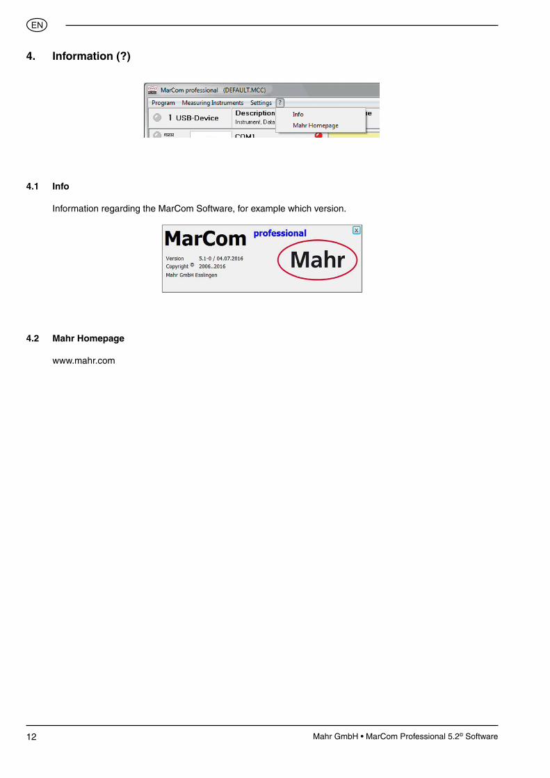
4. Information (?)
4.1 Info
Information regarding the MarCom Software, for example which version.
4.2 Mahr Homepage
www.mahr.com

13Mahr GmbH • MarCom Professional 5.2© Software
��
5. Parameterize Measuring Instruments
5.1 MC-I Switch
The MC-I Cable is fitted on one end with a jack bush so that it can connected to a relay (e.g. foot switch 4102058) with a jack plug (according to JIS C 6560, 3.5 mm), therefore multiple foot switches can be utilized via USB hubs to control individual or multiple measuring instruments.
• Connection: Description of the connected data cable (e.g. MC-I).
• Device: Description of the connected device type (e.g. switch)
• Description: A more detailed description can be entered (e.g. foot switch) in order to clearly identify the switch
• Measurements per Cycle: Enter the number of measurements per cycle for example: when you enter 3, the foot switch must be operated 3 times before a cycle can begin, this is important to the allocation of the measuring instruments.
Example: If by ”Measurements per cycle” 3 is entered then select parameterize a measuring instrument (see 5.2 Measuring Instruments) as “Data Request” via MC-I Switch. Select the appropriate switch and the option “with Measurement No. 2”, then every second time (2 times) the foot switch is operated a measured value will be transferred in the cycle. The first and third (1 and 3) are not activated, therefore no measured data will be transferred. In this situation another instrument could be allocated in in this first or third cycle. When measuring instruments with “Measurement No. 1” and “Measurement No. 3” have been allocated, those measured values which are obtained by the first and third activation of the foot switch transferred.
Note: Please make sure that when entering in “Measurements per cycle” and “with Measurement No.” that in the parameter window the measuring instruments correspond logically. For example do not enter “with Measurement No” 5, although by “Measurements per cycle” only 3 has been entered. • Actual Measurement No: Here the actual status of the cycle is shown, if necessary one can skip to a certain point in the cycle.

14 Mahr GmbH • MarCom Professional 5.2© Software
��
5.2 Measuring Instrument
In this menu all the most important settings for the individual measuring instruments can be administered.
• Connection cable: Select the connected data cable (e.g. 16EXu or Opto Duplex). When connecting the USB data cable, the cable will automatically be recognized and cannot be edited.
• Instrument: Select the connected measuring instrument (e. g. MarCator 1086) the selected instrument will also be displayed as a picture for easier recognition.
• Description: Enter an appropriate description of the connected measuring instrument (e.g. Dial Indicator 2) or the measuring task being conducted.
• Data Request: Select a data request, request measured values
With “None” the value must be send with the measuring instrument, for example with the Data button on the data cable or on the measuring instrument.
Note: Regardless of which data request has been selected the measured value can always be send directly from the instrument.
If the window is a light gray, the contents cannot be selected and the connected measuring instrument will not support request measured values. In this instance the measured value can be sent from the measuring instrument (e.g. by pressing the DATA button).

15Mahr GmbH • MarCom Professional 5.2© Software
��
Via a “MC-I Switch” (foot switch). Here you can select additional values with either “per Measurement” (i.e. each time the switch is operated a value will be sent) or “with Measurement No.” (i.e. the values that are to be send to the measuring cycle after X-times activation of the switch). How to define the measuring cycle can be found in section 5.1 MC-Switch.
Via the “Timer”; here you can set the time control of a cyclical data request. The cycle can be entered in hours, minutes and seconds. The timer cycle will be shown as a Timer symbol in the configuration window, the symbol can be used to start or stop the timer.
Via a “keypad”, request measured values with a predetermined button on the keyboard e.g. F1, F2 up to F12.
Note: The functions buttons F1, F2 etc. are deactivated in MS Excel!
Additionally, a pull-down menu for starting and stopping the timer is available. You can select whether the timer is to be also started and stopped via a function key (e.g. F1), MC-I switch (e.g. foot switch) or global via the timer button in the status window. In this way several timers for various measuring instruments can be simultaneously started and stopped.
Note: The Timer key to start and stop the timer is with selection of a transfer to using a “keyboard code” is not available and is not practical.

16 Mahr GmbH • MarCom Professional 5.2© Software
��
• Transfer to: Select the data format in which the values should be sent to (e.g. MS Excel, text file, keyboard code or a virtual interface box).
With “Text file” the measured values taken from a measuring instrument will be transferred to a text file; you can enter the path and the description of the text file with “File” and then “Text file-Settings”.
Note: When using several measuring instruments the values of each individual measuring instrument should be transferred into separate text file.
Zero setting: When using a RF device an additional point appears in the menu.
Here the type of action can be selected in which the RF device gives the command for zero setting. Whilst “Keypad” and “MC-I Switch” function identically to that of Data Request it is also possible to create an additional button on the user window which is clicked with the mouse.
17Mahr GmbH • MarCom Professional 5.2© Software
��
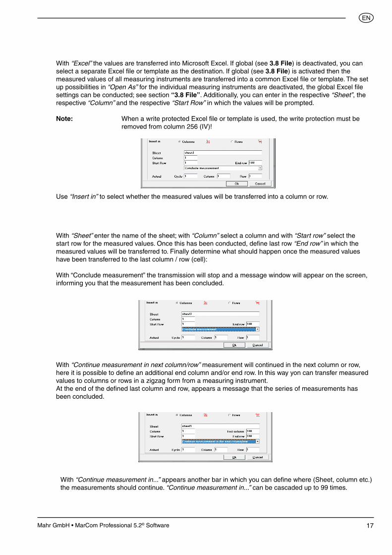
With “Excel” the values are transferred into Microsoft Excel. If global (see 3.8 File) is deactivated, you can select a separate Excel file or template as the destination. If global (see 3.8 File) is activated then the measured values of all measuring instruments are transferred into a common Excel file or template. The set up possibilities in “Open As” for the individual measuring instruments are deactivated, the global Excel file settings can be conducted; see section “3.8 File”. Additionally, you can enter in the respective “Sheet”, the respective “Column” and the respective “Start Row” in which the values will be prompted.
Note: When a write protected Excel file or template is used, the write protection must be removed from column 256 (IV)!
Use “Insert in” to select whether the measured values will be transferred into a column or row.
With “Sheet” enter the name of the sheet; with “Column” select a column and with “Start row” select the start row for the measured values. Once this has been conducted, define last row “End row” in which the measured values will be transferred to. Finally determine what should happen once the measured values have been transferred to the last column / row (cell):
With “Conclude measurement” the transmission will stop and a message window will appear on the screen, informing you that the measurement has been concluded.
With “Continue measurement in...” appears another bar in which you can define where (Sheet, column etc.) the measurements should continue. “Continue measurement in...” can be cascaded up to 99 times.
With “Continue measurement in next column/row” measurement will continued in the next column or row, here it is possible to define an additional end column and/or end row. In this way yon can transfer measured values to columns or rows in a zigzag form from a measuring instrument.At the end of the defined last column and row, appears a message that the series of measurements has been concluded.

18 Mahr GmbH • MarCom Professional 5.2© Software
��
When “Insert in” row is selected, then the above description applies according to the row.
In the field “Actual”, the cycle and the actual cell (row and column) in which the data is to be transferred is shown (defined). These values can be also changed, for example after deletion of measured values into a certain cell to be transferred. In this way data can be transferred to cells in which the previous value was deleted. Once the empty cells are used, “fill up” the transmission normally, continues without overwriting the previously transferred value.
The measurement cycle can be reset be either in the menu “Measuring Instruments - Reset Measuring Cycle “ (see 2.1 Reset Measuring Cycle) or the push button “Reset” in the status window.
Keyboard code settings: you can define 2 end markers (End marker 1 and End marker 2), once a measured value has been transferred the sequence of the End markers will be conducted, i.e. if, for example ENTER is selected, that corresponds to pressing the enter key on the keyboard (measured value is transferred and the position of the measured value depends upon the chosen End markers / sequence). In this way you can jump to any field in your form or table after a measured value has been transmitted.
With “keyboard code” transfer to, the measured values of the measuring instrument are transferred into the actual current position of the cursor. Therefore, it is possible to transmit the measured value independently of the software application. Measured values can therefore be transferred into MS Access, OpenOffice or into a CAQ program.

19Mahr GmbH • MarCom Professional 5.2© Software
��
In order to select the End marker you must click on the ENTER field and select the required character from the Pull-Down menu.
With the decimal separator select the decimal separator according the type used in the country you are in or according to type used in the application.
With “virtual interface box code” the measured values from the measuring instrument will be transferred to a virtual interface box, which for example is connected to a CAQ software.
20 Mahr GmbH • MarCom Professional 5.2© Software
��
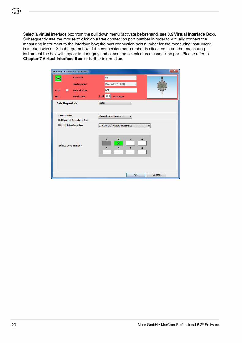
Select a virtual interface box from the pull down menu (activate beforehand, see 3.9 Virtual Interface Box). Subsequently use the mouse to click on a free connection port number in order to virtually connect the measuring instrument to the interface box; the port connection port number for the measuring instrument is marked with an X in the green box. If the connection port number is allocated to another measuring instrument the box will appear in dark gray and cannot be selected as a connection port. Please refer to Chapter 7 Virtual Interface Box for further information.
21Mahr GmbH • MarCom Professional 5.2© Software
��
6. Connecting RF Devices
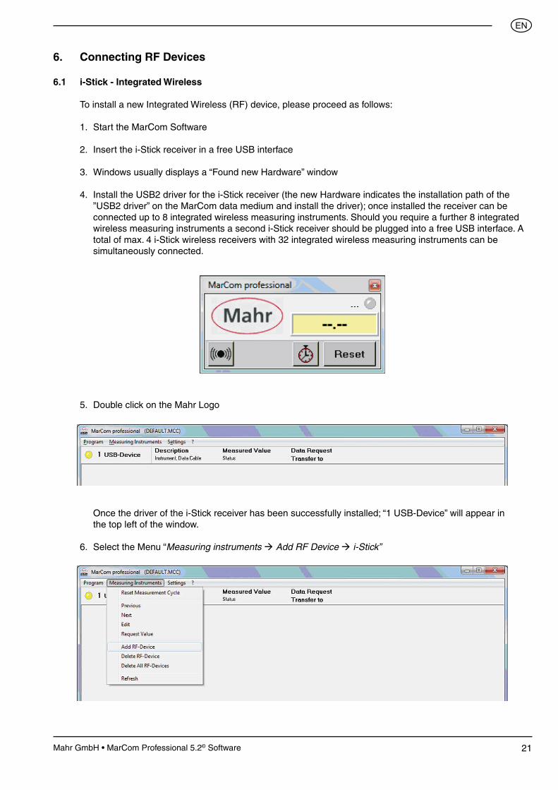
6.1 i-Stick - Integrated Wireless
To install a new Integrated Wireless (RF) device, please proceed as follows:
1. Start the MarCom Software
2. Insert the i-Stick receiver in a free USB interface
3. Windows usually displays a “Found new Hardware” window
4. Install the USB2 driver for the i-Stick receiver (the new Hardware indicates the installation path of the ”USB2 driver” on the MarCom data medium and install the driver); once installed the receiver can be connected up to 8 integrated wireless measuring instruments. Should you require a further 8 integrated wireless measuring instruments a second i-Stick receiver should be plugged into a free USB interface. A total of max. 4 i-Stick wireless receivers with 32 integrated wireless measuring instruments can be simultaneously connected.
5. Double click on the Mahr Logo
Once the driver of the i-Stick receiver has been successfully installed; “1 USB-Device” will appear in the top left of the window.
6. Select the Menu “Measuring instruments Add RF Device i-Stick”

22 Mahr GmbH • MarCom Professional 5.2© Software
��
7. The “Parameterize Measuring Instruments” window will appear.
8. Select a channel (01 to 03). We recommend that when connecting for the first time, that you leave channel set at 01, only change the channel if at a later date you experience any problems with transmission, then change the channel in the MarCom Software and the integrated wireless measuring instrument.
Note: The channel number must match the channel number of the measuring instrument!
9. Select the measuring instrument that is to be connected (e.g. MarCal 16EWRi or MarCator 1086Ri).
10. Enter an appropriate description for the Measuring Instrument (e.g. RF1)
11. Allot the measuring instrument an individual instrument number (from 001 to 999). The prefix e.g. 01 is the measuring station, this can be set under “Settings Enter a Measuring Station No.” (see Chapter 3.5 Measuring Station No.). The Measuring Station No. enables that several measuring positions in close proximity can be used as each instrument has its own individual number. Therefore, you will avoid inadvertently sending measured values from an integrated wireless receiver to a PC (Measuring Station) which has not been appropriately assigned.
Note: Never assign the same instrument number to several integrated wireless measuring instruments!

23Mahr GmbH • MarCom Professional 5.2© Software
��
12. In the Checkbox “ECO” you can activate the energy saving mode for the wireless data transmission, thus reducing energy consumption of the integrated wireless wire measuring instrument up to 30 %.
Note: In the “ECO mode”, the transmission speed will be reduced; rapid transmission intervals of <7 seconds are not recommended or possible. If the “ECO mode” is to be activated then the “ECO mode” on the integrated wireless measuring instrument must also be activated!
13. All other settings such Data Request, Transfer, etc. can be configured in MarCom just as if using a cable (see Chapter “5.2 Parameterize Measuring Instruments”).
14. Subsequently, you must press the “Connect RF-Device” button in order to establish a connection. The MarCom software will search for active integrated wireless measuring instruments; next select the connected measuring instrument (e.g. MarCal 16EWRi or MarCator 1086Ri).

24 Mahr GmbH • MarCom Professional 5.2© Software
��
15. Switch on the wireless measuring instrument.
16. Press the “Menu button” on the wireless measuring instrument for > 2 seconds.
17. “d OFF” (Digital Indicator) or “UnLoc” (digital caliper, digital micrometer) will appear in the display. With “UnLoc”press the „MENU“ resp. „=>“ -button until “OFF d” appears in the display (the wireless function is deactivated).
18. Press „ON/OFF“ by using wireless indicators, „OI“, by using wireless calipers and the „=>“ -button by using wireless micromers to activate the wireless function.
19. „d - - - -“ appears in the display (at present no instrument number has been allocated).
Note: If a instrument number has already been allocated (e.g. d 01002) this can be deleted by pressing the “PRESET” button (on a Digital Indicator) or the “OI” button (on a Digital Caliper), a new instrument number can now be assigned.
20. Press the „DATA“, resp. the „ü“ -button on the wireless measuring instrument to establish a connection.
21. The “Wireless symbol” in the digital indicator’s display will blink, once the connection has been established the wireless symbol will remain in the display; additionally the allocated instrument number will also appear in the display (digital indicator).
22. With a digital indicator briefly press the “Menu” button to exit the menu. When using a Digital Caliper 16 EWRi press and hold the “Menu” -button, when using micromers the „ü“ -button to exit the menu.
23. The “Connection symbol” in the top left corner becomes green. To exit the Parameterize Measuring Instruments window, press OK, this also confirm the setting in MarCom.
24. The first measuring instrument is connected, if further integrated wireless measuring instruments are required, repeat from step 6 . . .
25Mahr GmbH • MarCom Professional 5.2© Software
��
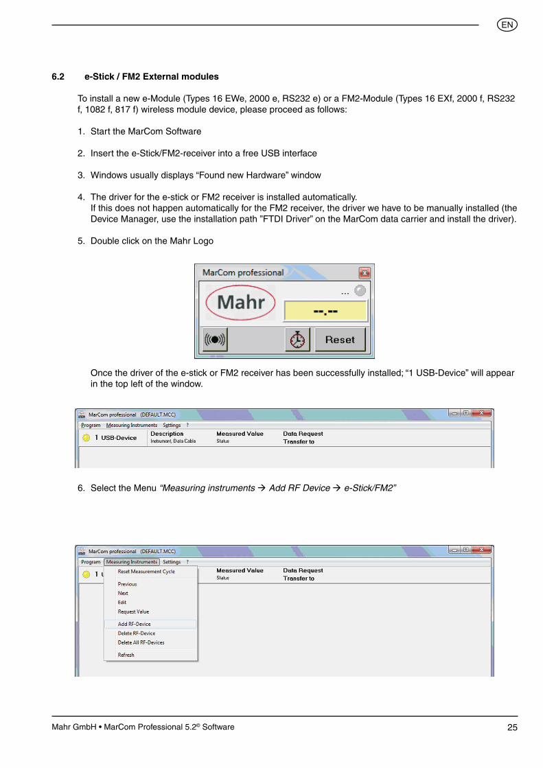
6.2 e-Stick / FM2 External modules
To install a new e-Module (Types 16 EWe, 2000 e, RS232 e) or a FM2-Module (Types 16 EXf, 2000 f, RS232 f, 1082 f, 817 f) wireless module device, please proceed as follows:
1. Start the MarCom Software
2. Insert the e-Stick/FM2-receiver into a free USB interface
3. Windows usually displays “Found new Hardware” window
4. The driver for the e-stick or FM2 receiver is installed automatically. If this does not happen automatically for the FM2 receiver, the driver we have to be manually installed (the Device Manager, use the installation path ”FTDI Driver” on the MarCom data carrier and install the driver).
5. Double click on the Mahr Logo
Once the driver of the e-stick or FM2 receiver has been successfully installed; “1 USB-Device” will appear in the top left of the window.
6. Select the Menu “Measuring instruments Add RF Device e-Stick/FM2”
26 Mahr GmbH • MarCom Professional 5.2© Software
��
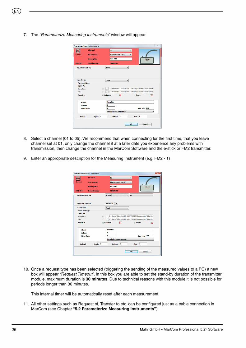
7. The “Parameterize Measuring Instruments” window will appear.
8. Select a channel (01 to 05). We recommend that when connecting for the first time, that you leave channel set at 01, only change the channel if at a later date you experience any problems with transmission, then change the channel in the MarCom Software and the e-stick or FM2 transmitter.
9. Enter an appropriate description for the Measuring Instrument (e.g. FM2 - 1)
10. Once a request type has been selected (triggering the sending of the measured values to a PC) a new box will appear “Request Timeout”. In this box you are able to set the stand-by duration of the transmitter module, maximum duration is 30 minutes. Due to technical reasons with this module it is not possible for periods longer than 30 minutes.
This internal timer will be automatically reset after each measurement. 11. All other settings such as Request of, Transfer to etc. can be configured just as a cable connection in MarCom (see Chapter “5.2 Parameterize Measuring Instruments”).

27Mahr GmbH • MarCom Professional 5.2© Software
��
12. To establish a connection with the sender, the Connect button in the top left must be activated; the MarCom Software only scans after active senders in the transmission range.
13. Press the data button on the wireless module so long (ca. 5 seconds) until the red LED on the wireless sender is extinguished and the green LED briefly lights up.
14. The Serial No. should appear in the configuration window, the connection window should then close. Press the “OK” button to close configuration window.
15. If you changed the operation time “Request Timeout” (see section 10) you will be asked to press the connection button again on the sender. By this you can transfer the new time setting to the module. This will be only possible if you have already connected the transmitter. Afterwards the configuration window closes automatically.
16. The Sender must be returned to the measuring mode, to do so briefly press the data button on the sender. The blue LED is now continuously lit.
Note: The sender is now ready for request, as previously set, see section 10. This means after this is completed and the blue LED is extinguished, it first possible to enable a remote request by pressing the data button on the receiver.

28 Mahr GmbH • MarCom Professional 5.2© Software
��
7. Virtual Interface Box
In order to use the new Mahr virtual interface box and conveniently connect you Mahr measuring instrument to a CAQ software, you must firstly install the actual MarCom Professional 5.2. The driver for the virtual interface box is automatically installed when installing MarCom.
Please proceed as follows:
1. When starting MarCom, the small status window appears on the screen, to open the configuration window double click on the Mahr logo
2. Before you connect the measuring instrument to the virtual interface box, you must beforehand select and activate a virtual interface box. To do this open the “Emulation of Interface Box” menu under “Settings”.
3. In the following dialog window you can activate up to 4 virtual interface boxes. These virtual interface boxes must be allocated an interface (e.g. COM 3) and a box type (e.g. Mux50 Mahr-Box), and subsequently the appropriate check box must be activated. Furthermore the allocation of a foot switch for data request to each Interface Box can also be conducted in this window.

29Mahr GmbH • MarCom Professional 5.2© Software
��
In the configuration window the individual measuring instruments can be selected which will be subsequently the transfer to in the virtual interface box, the individual measuring instruments are thus virtually connected to the virtual interface box (see following). Therefore; you can connect a USB or an integrated wireless measuring instrument simply to a third party software, for example, to a CAQ program, as if you are connected via an interface box (Multiplexer).
4. Please proceed as explained in Chapters “5 Parameterize Measuring Instruments” and 6 “Connecting RF Devices” with the connection of your measuring instruments (e.g. integrated wireless measuring instruments, USB data cable, MC-I foot switch, etc.).
5. To connect individual measuring instruments to the inputs on the virtual interface box, please open the configuration window of the appropriate measuring instrument. In this window please select as “Transfer to” the Virtual Interface Box instead of the standard setting; Excel.
In the pull down menu select Virtual Interface Box, which you have previously activated in “Settings – Virtual Interface Box.” Subsequently use the mouse to click on a free connection port number in order to virtually connect the measuring instrument to the interface box. The port connection port number for the measuring instrument is marked with an X in the green box.

30 Mahr GmbH • MarCom Professional 5.2© Software
��
If the “Select port number” is allocated to another measuring instrument the box will appear in dark gray and cannot be selected.

31Mahr GmbH • MarCom Professional 5.2© Software
��
6. Once the “Select port number” has been selected, close the configuration window with OK and continue with the next measuring instrument. When all your measuring instruments have been virtually connected to the interface close both configuration windows.
Note: To transfer measured values, the virtual interface box must be activated and the small status window is active.
In order that you do not have to manually start the MarCom software after every new start or reboot of the PC, you can add MarCom to the “Windows Autostart”, to do this activate the Autostart in the Settings menu (please refer to Chapter 3.10 Autostart).
7. You have now successfully completed the connection of your measuring instruments to the virtual interface box Mux-50 and activated the Box (in this example) to the COM 3 interface. Subsequently you must assign your CAQ software to the new interface box.
In the following screenshots show an example from qs-Stat to Q-Das.
8. In qs-Stat select the Characteristics Type of the Input Type of a Mux-50 compatible interface box (e.g. Bobe M (Mux), Brecht Mux 8, Mitutoyo Mux50 etc.).

32 Mahr GmbH • MarCom Professional 5.2© Software
��
Ill: qs-Stat
Ill: MarCom
9. Once the Input Type has been selected (in this example a Bobe M (Mux), select the device settings for this type. Then select the interface for the interface box (in this example COM 3) and a channel (Port Connection No.) of the connection measuring instrument.
10. Finally check the configuration of the interface settings, usually the default settings can be used.
11. The configuration of the virtual interface box and the CAQ software is now completed and you can now begin your measurements.
33Mahr GmbH • MarCom Professional 5.2© Software
��
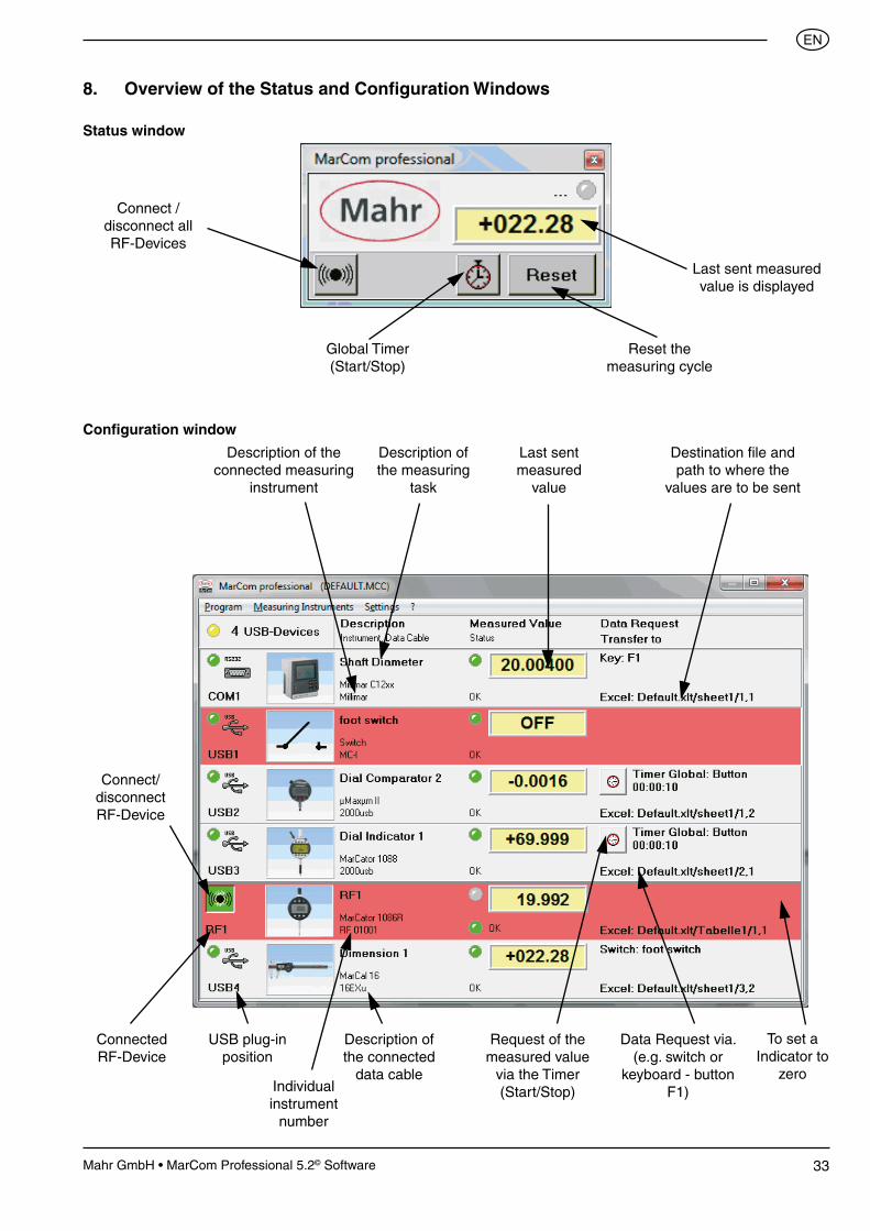
USB plug-in position
Description of the connected
data cable
Request of the measured value
via the Timer (Start/Stop)
Data Request via. (e.g. switch or
keyboard - button F1)
Description of the connected measuring
instrument
Description of the measuring
task
Destination file and path to where the
values are to be sent
Last sent measured
value
Connect/disconnect RF-Device
Connected RF-Device
Individual instrument
number
8. Overview of the Status and Configuration Windows
Status window
Global Timer (Start/Stop)
Reset the measuring cycle
Last sent measured value is displayed
Configuration window
Connect / disconnect all RF-Devices
To set a Indicator to
zero

34 Mahr GmbH • MarCom Professional 5.2© Software
��
9. Implementing a Remote Control
The Remote Control (4102221) no external driver is required. Once a USB receiver has be connected Windows own driver will be installed. After the this driver has be installed you can press a button on the remote control which simulates a keyboard command, see above illustration.With MarCom these keyboard commands can be assigned functions.
In the shortlist you can select functions for each button on the remote control. Please be aware the function buttons “Page up” and “Page down” are blocked for all other applications, once the MarCom is exited these functions button resume their original function.
Page down
F5
Page up
No function

35Mahr GmbH • MarCom Professional 5.2© Software
��
10. RS232 Settings on a measuring instrument
With measuring instruments that have a free configurable RS232 interface and cannot be directly connected to a Serial COM port or a USB port with a USB data cable require a RS232-USB adapter cable. The RS232 parameter must be set up according to the pre-configured MarCom Software, in the majority of cases this is the standard setting of the measuring instrument, nevertheless these should also be checked.
As to set up these parameters on the appropriate measuring instrument, please refer to the operating instruments of the measuring instrument.
If an adapter cable is used, the original RS232 data cable of the measuring instrument is required (see Order no. in brackets).
The settings are as follows:
Adapter cable Millimar USB (for Millimar 1240, C1208, C1210, C1216, C1245, S1840 etc.) Order no.: 4102331 + (7024634)
Millimar Millitron 1240 Protocol M1240 R/D COMPUTER Format 8 N 1 Baud 9600 Handshake kein Prot — Baud 9600 Interface RS232C Char 8n1
Adapter cable 817 USB (for Digimar CX1, CX2, 817 CLM etc.) Order no.: 4102333 + (7024634)
817 CLM / MarCheck Menü 13. Data and printer Interface RS232 Out User RS232 Baudrate 9600 Data format 1. No parity 8 Bits Interface mode 1. Handshake ON (CTS)
CX1 Channel 5 Baudrate 9600 Data format 1. No parity 8 Bits Interface mode 1. Computer or 4. Data manual transmit Interface mode 1. Computer requires CTS
CX2 FORMAT 8-N-1 HANDSH NONE BAUD 9600
Adapter cable MSP 2 USB Order no.: 4102334 + (4102711)
MSP 2 QuadraChek Transmit value/ Send meas. list Baud 4800 Baud 4800 FORMAT 7-E-2 Dat 7 Par E Stp 2 Close CR
Adapter cable Millimar 832 USB Order no.: on Request Baud 4800

36 Mahr GmbH • MarCom Professional 5.2© Software
��
11. Technical Data
11.1. e-Modules
Types: 16 EWe, 2000 e, RS232 e
Radio transmission frequency 2.4GHz Technology Bluetooth Smart Qualified Design ID (BlueGiga BLE112) B018943 Battery 1 x CR 1/3N (3V) Operational temperature range +10°C … +35°C Relative humidity 30% - 90% (non-condensing) Appliance class IP40 Transmission range (depending on local conditions) approx. 10m Dimensions L x W x H 52 x 26 x 16 mm
11.2 e-Stick Receiver
Type: e-stick
Transmission frequency 2.4GHz Interface USB Technologie Bluetooth Smart Manufacturer/type BlueGiga / BLED112Transmission range (depending on local conditions) approx. 10m
11.3 FM2-Modules
Types: 16 EXf, 2000 f, RS232 f, 1082 f, 817 f
Radio transmitter frequencies 433.05MHz - 434.79MHzFrequency channels 68 Transmitter batteries (housing type A) 1 x CR 1/3 N (3V) Operational temperature range +10°C … +35°C Relative humidity 30% - 90% (non-condensing) Appliance class IP40 Transmission range (depending on local conditions) up to 100m Dimensions L x W x H 52 x 26 x 16 mm
11.4 FM2-Receiver
Type: FM2
Radio transmitter frequency 433.05 - 434.79MHz Frequency channels 68 Power supply 5V via USB connection Interfaces USB / RS232 (4800,8,N,1) Operational temperature range +10°C … +35°C Relative humidity 30% - 90% (non-condensing) Appliance class IP40 Transmission range (depending on local conditions) up to 100m Dimensions L x W x H 120 x 58 x 25 mm USB cable length < 3m RS232 cable length < 3m

37Mahr GmbH • MarCom Professional 5.2© Software
��
Notes
........................................................................................................................................................
........................................................................................................................................................
........................................................................................................................................................
........................................................................................................................................................
........................................................................................................................................................
........................................................................................................................................................
........................................................................................................................................................
........................................................................................................................................................
........................................................................................................................................................
........................................................................................................................................................
........................................................................................................................................................
........................................................................................................................................................
........................................................................................................................................................
........................................................................................................................................................
........................................................................................................................................................
........................................................................................................................................................
........................................................................................................................................................
........................................................................................................................................................
........................................................................................................................................................
........................................................................................................................................................
........................................................................................................................................................
........................................................................................................................................................
........................................................................................................................................................
........................................................................................................................................................
........................................................................................................................................................
........................................................................................................................................................
........................................................................................................................................................
........................................................................................................................................................
........................................................................................................................................................
........................................................................................................................................................
........................................................................................................................................................
........................................................................................................................................................
........................................................................................................................................................
........................................................................................................................................................
........................................................................................................................................................
........................................................................................................................................................
........................................................................................................................................................
........................................................................................................................................................
........................................................................................................................................................
........................................................................................................................................................
........................................................................................................................................................
........................................................................................................................................................
........................................................................................................................................................
........................................................................................................................................................
........................................................................................................................................................
........................................................................................................................................................
........................................................................................................................................................
........................................................................................................................................................
........................................................................................................................................................

© by Mahr GmbH
We reserve the right to make changes to our products, especially due to technical improvements and further developments.
All illustrations and technical data are therefore without guarantee.