mark sensors - mh-electronics.com - home · mx10 mx10f series mp2f (power supply unit) ms-s30w gr...
TRANSCRIPT

MX10
MX10F series
MP2F (power supply unit)
MS-S30W
GR series
MA series
MC series
MU10 series
Mark Sensors
Mark
Sensors
409
HOME

410
Mark
Sensors
Mark Sensors
Sample Applications
Checking for upside-downelectronic components
Sorting by cap Register mark detection with U-shaped through-beam sensor
Checking for upside-downchip resistors
Detection of marks onlaminated tubes
Detection of labels on bottles
These sensors detect the brightness and saturation of color print orpaint on objects without making contact with the object and are mainlyused on bag making machines, automatic wrapping machines, printingpresses, etc. Color sensors are used for various types of control suchas detection of register marks in red, blue, yellow, etc. for positioning forwrapping and cutting. A broad range of applications for these sensorsalso include differentiation between colors where incorrect colors maycause quality control problems and the detection of different levels ofreflectance between paint colors on the front and back sides of objects(parts) in a production line checking for the incorrect side facing up.
Sensor for timing Register mark
YellowPattern Red Blue yellowRed green
Luminescence mark sensorModel GR12UVS
Detection CapabilityReference for selection of mark sensor for detecting registermarks (correlation between mark colors, background colors andlight source colors)
Sensor light source:R: red light G: green light B: blue light
Mark color
Background colorBlack Blue Green Red Orange Yellow White
WhiteYellowOrange
RedGreenBlueBlack
RGBRGBRGBRBBB
RGBRGBRGBRBB
B
RGBRGBRGB
R
BB
GBG
GB
RRBRB
BG
GBRGBRGBRGB
B
GG
RGBRGBRGB
BB
GBRGBRGBRGB
(*) Detection may not succeed depending on the shading, etc. Be sure to check the
operation with samples.
The ultraviolet LED used as the light source and the optical systemintegrating the light-sensitive element with enhanced sensitivity tovisible light allow easy detection of fluorescent marks (hiddenmarks, fluorescent glue, etc.).Applications:
Detection of fluorescent register marksDetection of presence of fluorescent glueDetection of presence of transparent sheet containing fluorescer

418
415
420
424
428
430
412
411
Mark
Sensors
Mark Sensors
List of models
Type
Tun
gste
nla
mp
MP2F (Special power supply unit for MX Series)
Gene
rictyp
eO
ptic
alfib
erA
mpl
ifier
built
-inLE
D
Detectionmethod
Limitedreflection type
Through-beam typeReflective
type
Depends on fiberoptic cable
Limitedreflection type
U-shapedthrough-beam
Model
MX10
MX10F
MS-S30W
GR12RSGR12RGR12GSGR12GGR40RGR60RGR12UVSMA-U2RMA-U2RPNMA-U2GMA-U2GPNMA-U2BMA-U2BPNMC-U2RMC-U2RTCMC-U2GMC-U2GTCMC-U2BMC-U2BTCMU10NMU10NR
Fib
erop
ticca
ble
FT(Through-
beam)
FR(Reflective)
FX(Coaxial
reflective)
FS(SUS coaxial
reflective)
Lightsource
Tungstenlamp
White LED
Red LED
Green LED
Red LED
Red LED
Green LED
Blue LED
Red LED
Green LED
Blue LED
Green LEDRed LED
Ultraviolet LED
Detecting distance
13mm(8 mm from lens hood)
20mm
5mm
8mm
1.5mm
30mm±2mm
12mm±2mm
20~70mm20~90mm
Interval betweentransmitter and receiver: 2mm fixed
Interval betweentransmitter and receiver: 2mm fixed
Interval between transmitterand receiver: 10 mm fixed
Smallestdetectablemark width
0.1mm
1mm
0.1mm
0.5mm
1mm
――
1mm
2mm
Applicablepower supplyunit (amplifier)
MP2F
PS SeriesIP Series
Seepage...
12mm±2mm
Power supply unit

412
Mark
Sensors
MXseries
Tungsten lamp typeprovides high resolution MX10 Series
is capable of detecting yellow markson white background
MX10F SeriesFiber type allows flexible installation
Response time of 20 µs max. and cyclic responsefrequency of 25 kHz provides high-speedresponse and detection of small “register” marks
TypeDetection method Detecting distance Model Operation mode Output mode
Reflective type
Through-beam type
Reflective type
Coaxial reflective type
* Model Nos. for fiber type sensors are set model Nos. respectively including an amplifier (MX10F) and a typical fiber optic cable.
20mm
5mm
8mm
1.5mm
*F
iber
type
13mm(8 mm from lens hood surface)
MX10
MX10F-FT
MX10F-FR
MX10F-FX
MX10F-FS
Light-ON/Dark-ON selectable
Current output
Voltage output
Model Power supply
AC/DC100~240V
Power supplied to sensor Operation mode Output mode
MP2F DC12V、100mADC4.5V、780mA
Timer functionselectable
Relay outputCurrent outputVoltage outputBurnt-out lamp
alert output
Power supply unit
Optional PartsType
Standard lensStandard
lamp
Lamp
Model
L12
LM66
LM67
DescriptionAspheric lens offering high resolution (accessory)
(accessory)
Filament orientationdifferent from LM66
Mark Sensors

413
Mark
Sensors
MX Rating/Performance/Specification
Environmental Specification
Type
Model
Fiber unit type
Detection method
Detecting distance
Power supply
Current consumption
Output mode
Operation mode
Spot diameter
Smallest detectable
mark width
Activation position repeatability
Response time
Cyclic response frequency
General-purpose type
MX10
Optical fiber type
MX10F–––
Reflective (differential comparison)
13mm (8 mm from lens hood)
Sensor: 12 – 24V DC ±10% Ripple: 10% max.Lamp: 4.5V AC/DC4.5V ±10% 50/ 60Hz
Sensor: 35 mA max., Lamp: AC4.5V 3.6W(0.8A)
Light-ON/Dark-ON selectable (with switch)
0.1mm
20 µs
10 kHz max.
Tungsten bulb
Sensitivity adjustment: multi-turn volume dialPosition indication on dial: ruler on drum
Operation indicator (red LED)
Zinc die-cast
Permanently attached cord (vinyl insulated ø6)Two 0.5 mm2 and three 0.3 mm2 cores, 4 m
600 g max.
MP2F
MX10-30, MX10-60 and MX10-120 for minute objectdetection are also available. Contact Takex for
details.
Tungsten bulbReplacement: insert socketTime for stabilization: about 30 minutes after illumination / Life: 10,000 hours av. (when usedaccording to rating)
Mounting: M5 x 5 screw (mountable in three orientations)Wiring: core extension: 20 m with standard cord, 50 m with cord of 1.25 mm2 or thicker
[Lamp voltage must be 4.5 V min. Shielded wires must be used.]
–––––––––
1 x 4mm ø15mm ø6mm ø6mm ø1.5mm
0.1mm (black mark on whit background)1mm min.
(opaque object)0.1mm (black mark on whit background)
Current output: Rating: sink current 100 mA (30 VDC) max.
Voltage output: Rating: output impedance 3.9 kΩ (residual voltage: 1 V max.)
FTThrough-beam type
20 mm max(0~25mm)
FRReflective type Coaxial reflective type
5 mm max(0.5~8mm)
FX
8 mm max(0.5~12mm)
FS
1.5 mm max(0.2~3mm)
Rat
ing/
perf
orm
ance
Spe
cific
atio
n
Light source
Adjustment
Indicator
Case material
Connection
Mass
Applicable amplifier
Notes
Env
ironm
ent
Ambient light
Ambient temperature
Ambient humidity
Protective structure
Temperature rise
1,000 lx max. (radiation from above)
Storage: –10- +50 °C (non-freezing)
35-85%RH (non-condensing)
IP66
15deg(Case temperature as mounted on iron plate of 60 x 80 x 1.6 (t))

414
Mark
Sensors
MX
MP2F
8 9 10 11 12 13 14
1 2 3 4 5 6 7
Input + + + 12V 0V 4.5V 0V
+ Black (output)
Brown ( )
Blue (0V)
To (9)
To (11)
To (12)
DC12 ~24V
Burnt-out lamp alert outputVoltage-current output
AC/DCAC/DC100
240V〜
Sh
ield
ed
Bla
ck
Re
d
Wh
ite
Gre
en
Blu
e
MX10FMX10
COM COM NO NO NC
Relay output
Gate sensor
Current outputVoltage output External gate
Input/Output Circuit and Connection
Connection Example
Principle of Operation
Light emitted from the lamp goes through the half mirrorand object lens and then converges on the detection mark.Then the converged light is reflected as a beam accordingto the brightness, saturation, etc. of the mark and goesthrough the half mirror and object lens to enter the light-sensitive element (1), which is called detected light.While the light from the lamp is radiated on the mark,some of it also goes through the guide glass andsensitivity adjustment mechanism to enter the light-sensitive element (2), which is called reference light.The two types of light (detected light and reference light)are converted into electric signals in the individual light-sensitive elements (1) and (2), which are input into thedifferential amplifier for comparison and output as adetection signal.
Inte
rna
l c
irc
uit
Red
Black:
White
output
0V
DC12~24V
OP.L
Black:
Red
White
Green
Blue
output
ShieldedGround
0V
DC12~24V
AC/DC4.5V
Half mirror
LampReference light
Sensitivity adjustment (SENS)
Output
Differential amplifier
Detected light
Light-sensitive element (1)
Light-sensitive element (2)
Guide glass
Detection mark

415
Mark
Sensors
MP2F① EXT. GATING
Polarity selector switch for external synchronization signal.
Set at ON for L mode and OFF for H mode.
② Delay time range selector switch
ON: 1-10 seconds / OFF: 0.1-1 second
③ Operation mode selector switch
Timer disabled, one-shot, on-delay, off-delay, latch
④ Power indicator (green LED)
⑤ Operation indicator (red LED)
⑥ Sensor lamp burnt-out bulb alert indicator (red LED)
⑦ Delay time adjustment
Rating/Performance/SpecificationType
Power supply
Power consumption
Operation mode
Output mode
Input mode
Minimum input duration
Power supplied to sensor
External gate
Response time
MP2F
AC/DC100~240V ±10%
25 VA max.25 W max.
Timer functions (on-delay, off-delay, one-shot, latch, timer disabled)Delay time: 0.1-1 s or 1- 10s
Voltage input Straight polarityH : 6~12V
Input impedance 4.7 KΩL : 0~1V
400 µs (in off-delay, one-shot and latch modes)DC12V ±5% 100mA/DC4.5V ±5% 0.8A
Contact input/voltage input Voltage inputH : 6~12V
H/L mode selectableL : 0~1V
10 µs max. (with timer disabled)
P.L: power indicator (green LED)OP.L: operation indicator (red LED)
LAMP ALARM: burnt-out bulb alert indicator (red LED)
TIME: delay time adjustment (0.1-1s/1-10s)
EXT. GATING switch: for external gating polarity switching; ON for L, OFF for HDelay time range selector switch: ON for 1-10s, OFF for 0.1-1 s
Operation mode selector switch: for switching between timer disabled, one-shot, on-delay, off-delay and latch
Resin
Plug-in terminal block
350 g max.
MX10/MX10F Series
Relay output 1c
Rating: 3A (250 VAC) noninductive load
Current output/voltage output Burnt-out bulb alert output(current output/voltage output)
Rating: Current output: sink current 100 mV (30 VDC) max.Voltage output: output impedance 3.9 kΩ (12 VDC)
Rat
ing/
perf
orm
ance
Spe
cific
atio
n
Indicator
Volume
Switch
Material
Connection
Mass
Applicable sensor
Environmental Specification
Env
ironm
ent
Ambient temperature
Ambient humidity
Protective structure
Vibration
Shock
Dielectric withstanding
Insulation resistance
–10 - +50 °C (non-freezing)
35-85%RH (non-condensing)
IP20
10-55 Hz / 1.5 mm amplitude / 2 hours each in 3 direction
1000m / s2 / 2 times each in 3 directions
Between power supply terminal and contact terminal: 1,500 VAC for 1 minute / Between contacts: 1,000 VAC for 1 minute
Between power supply terminal and contact output terminal/contacts: 500 VDC, 100 MΩ or higher
①⑦
⑥
⑤④
③
②

416
Mark
Sensors
MP2F Input Circuit
Output Circuit
Operation
Selector Switches
(1)When not using external gating in modes
other than the latch mode, set H for EXT.
GATING.
(2)In the latch mode, gating input can be
used for reset with EXT. GATING setting
“H” (L input).
(3)In the latch mode with EXT. GATING
setting “L,” the output signal is activated
when the mark sensor and gating sensors
are activated and the output is held until
the gating sensor is deactivated.
(4)Delay time can be set with the TIME
volume.
Minimum/maximum delay time can be set
at “MIN”/“MAX.”
(Timer operation)
11
9
12
+12V11
8
12
+12V
Sensor input Gating input
Relay output Voltage output
7 NC
5 COM
6 NO
11
10
12
+12V
Burnt-out bulb alert output
11
4
12
+12V
(Note) At power-up, about 3 V is output
until the lamp is illuminated.
Contact capacity: 250 VAC 3 A(noninductive load)
(Operation with timer disabled)
(1) EXT. GATING
Polarity selector switch for
external synchronization signal.
Set at ON for L mode and OFF
for H mode.
(2)TIME
Delay time range selector switch.
Setting at ON specifies a range
between 1 and 10 seconds, OFF
between 0.1 and 1 second.
(Timer is disabled when NORM
is ON.)
Operation withtimer disabled
One-shot On-delay Off-delay Latch
ON OFF ON OFF ON OFF ON OFF
(3)Operation mode switchingSet the selector switches according to the output mode.
(Note) Switches with settings not shown in the figure do not affect theoperation of the respective modes.
t
t
tt
t tt
t
(t indicates delay time)
Mark sensor
Gating sensor
(One-shot)
(On-delay)
(Off-delay)
(Latch)
ONOFF
OFF
OFF
OFF
ON
ON
Output
ON
Mark sensor
Gating sensor
ON
ON
OFF
OFF
Output
Output
(GATE「H」ON)
(GATE「L」ON)
OPEN
ON OFF
ON OFF
ON OFF
ON OFF
1-10 seconds 0.1-1seconds
“H”ON or open“L”ON
ON OFF

417
Mark
Sensors
60 ± 2 mounting hole (elongate)
12
72
3 (max)
9
14
100
2616
609
4.5
(max)6DIN rail35mm
MX・MP2F Dimensions (in mm)
MX10F
The orientation of the attachment of fiber optic
cable is fixed. Same as for MX10 except for fiber optic cable
attachment.
10
M4 x 0 5(2 nuts and 1 internal toothed
washer provided)
15
M6 x 0.75
(2 nuts and 1 internal too hed washer provided)
10
M4 x 0 5
(2 nuts and 1 internal too hed washer provided)
5ø1 5
ø1.1 Annealed stainless steel tube
Model FT (through-beam) 500 mm Model FR (reflective) 500 mm Model FX (coaxial reflective) 500 mm Model FS Annealed stainlesssteel tube 70 mm
Fiber optic cable(enlarged view of tip)
Top lens
75 145
2841 5
30
5
58
38.5
15
21
Moisture-proof material case
37 28
Cord: 4 m ø6
P otective cover
Display panel
Mounting screws M5 x 5mm
(8)58
38 5
151 5
12 56
37
28
ø18 ø9
Cord: 4 m ø6
Fiber optic cable
MX10
MP2F
Screw tighteningtorque: 0.3 N・m
Screw tighteningtorque: 0.3 N・m
Screw tighteningtorque: 0.3 N・m

418
Mark
Sensors
Light-ON/Dark-ON selector switch
Stability indicator (green)
Operation indicator (orange)
8-position indicator
D.ON L.ON
SENS.
MIN. MAX.
8-turn sensitivity adjustment
TAKEX
MS-S30W
MS-S30W High-response sensor
supporting a wide rangeof colorsWhite LEDDetecting distance 30 mmHigh response 30 µsMulti-turn pot. for easy adjustment
Type
Panel Layout and Functions
Detectionmethod Detecting distance Model Operation
mode Output mode
Limitedreflection type
MS-S30WLight-ON/Dark-
ON selectorswitch
NPN/PNP opencollector
SENS.
Adjustment pot. for fine tuning. Turning clockwise increases
the amplifier sensitivity and allows detection of marks in dark
colors.
Turning beyond the MIN. or MAX. makes a clicking sound.
8-position indicator
Allows reading of the current sensitivity setting made with the
8-turn adjustment.
L.ON/D.ON
Light-ON/Dark-ON selector switch
Stability indicator
Illuminated when the received light intensity level is 90% or
lower or 110% or higher of the operation level.
Operation indicator
Illuminated when the output transistor is activated.
30mm±2mm
White LED mark sensor
419
Mark
Sensors
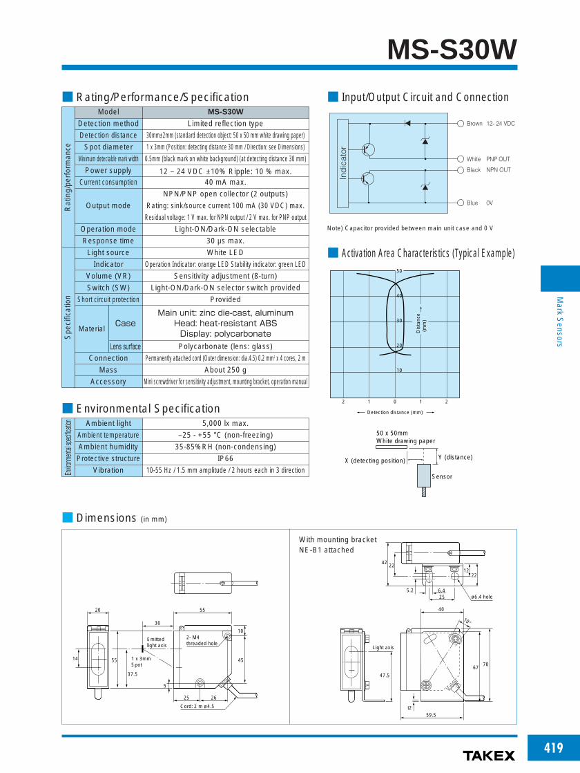
MS-S30W Rating/Performance/Specification Input/Output Circuit and Connection
Activation Area Characteristics (Typical Example)
Dimensions (in mm)
Model
Detection method
Detection distance
Spot diameter
Minimum detectable mark width
Power supply
Current consumption
Output mode
Operation mode
Response time
MS-S30W
Limited reflection type
30mm±2mm (standard detection object: 50 x 50 mm white drawing paper)
1 x 3mm (Position: detecting distance 30 mm / Direction: see Dimensions)
0.5mm (black mark on white background) (at detecting distance 30 mm)
12 – 24 VDC ±10% Ripple: 10 % max.40 mA max.
NPN/PNP open collector (2 outputs)
Rating: sink/source current 100 mA (30 VDC) max.
Residual voltage: 1 V max. for NPN output / 2 V max. for PNP output
Light-ON/Dark-ON selectable
30 µs max.
White LED
Operation Indicator: orange LED Stability indicator: green LED
Sensitivity adjustment (8-turn)
Light-ON/Dark-ON selector switch provided
Provided
Polycarbonate (lens: glass)
Permanently attached cord (Outer dimension: dia.4.5) 0.2 mm2 x 4 cores, 2 m
About 250 g
Mini screwdriver for sensitivity adjustment, mounting bracket, operation manual
Main unit: zinc die-cast, aluminumHead: heat-resistant ABSDisplay: polycarbonate
Rat
ing/
perf
orm
ance
Spe
cific
atio
n
Light source
Indicator
Volume (VR)
Switch (SW)
Short circuit protection
Material
Connection
Mass
Accessory
Case
Lens surface
Environmental Specification
Environmentalspecification Ambient light
Ambient temperature
Ambient humidity
Protective structure
Vibration
5,000 lx max.
–25 - +55 °C (non-freezing)
35-85%RH (non-condensing)
IP66
10-55 Hz / 1.5 mm amplitude / 2 hours each in 3 direction
Ind
icat
or
Brown 12- 24 VDC
White PNP OUT
Black NPN OUT
Blue 0V
Note) Capacitor provided between main unit case and 0 V
21012
50
40
30
20
10
Dis
tanc
e (
mm
)
Detection distance (mm)
Sensor
Y (distance)X (detecting position)
50 x 50mmWhite drawing paper
ø6.4 hole
6.425
59.5
40
Light axis
10°
5.2
t2
42 22
22
7067
47.5
12
Emitted light axis
1 x 3mmSpot
45
37.5
5514
10
25 26
5520
30
2- M4 threaded hole
Cord: 2 m ø4.5
5
With mounting bracket NE-B1 attached

420
Mark
Sensors
GRseries
Generic type with LED
Water resistance to IP 67standard allows washingtogether with lineequipment.This is achieved bycomplete resin filling
Ultraviolet luminescence mark sensorModel: GR12UVSIdeal for detection of hidden or fluorescent marks
Sample ApplicationDetection of transparent register marks or stickers containing fluorescer
Marks reliably detected without influence of background color or pattern
Mark sensor with detecting distance of30-120 mm also available
Model: GR100R (PN)
TypeDetectionmethod Detecting distance Model Light source Operation mode Output mode
Limitedreflection type
12mm±2mm
20~70mm
20~90mm
GR12RS
GR12R
GR12GS
GR12G
GR40R
GR60R
GR12UVS
Red LED
Green LED
Red LED
Ultraviolet LED
Light-ON/Dark-ON selector
switch
NPN opencollector
Side-on
GR12UVS
Transparent register mark
12mm±2mm
Mark sensor

421
Mark
Sensors
GR Rating/Performance/Specification
Environmental Specification
Type
Detection method
Detecting distance
Power source
Current consumption
Output mode
Operation mode
Spot diameter
Smallest detectable
mark width
Response time
Side-on
Head-on
GR12RS
GR12R
GR12GS
GR12G
GR40R
–––––––
20~70mm
ø1.5mm *1 ø0.5mm
1 mm(black mark on white background)
Red LED(680nm)
25 mA max. 26 mA max.
NPN open collector outputRating: sink current 100 mV (30 VDC) max.
Light-ON/Dark-ON selectable (with switch)
GR60R
–––––––
GR12UVS
–––––––
12mm ±2mm20~90mm
ø4mm *1
1 mm(red mark on white background)
Green LED(568nm)
Ultraviolet LED(375nm) *2
30 mA max.
Zone-reflective type
12mm ±2mm
ø1mm
1 ms max.
4-turn sensitivity adjustment without stopper provided
Light reception indicator (red LED)Stability indicator (green LED)
Light reception indicator (orange LED)Stability indicator (green LED)
Provided
Polycarbonate (lens of GR12UVS: glass)
Permanently attached cord (outer diameter: dia.4.2)0.3 mm2 x 3cores, 3 m
About 100 g max.
*1 At detecting distance 40 mm
*2 (Note)
Do not look straight into the light source while illuminated. The strong UV ray may damage the eye if
seen only for a short time. If it is unavoidably necessary to look, be sure to use glasses, etc. with UV
protection.
––––––––––
Red LED(660nm)
25 mA max.
12 – 24 VDC ±10% Ripple: 10 % max.
Rat
ing/
perf
orm
ance
Spe
cific
atio
n
Light source (Lightwavelength)
Volume (VR)
Indicator
Short circuit protection
Case material
Connection
Mass
Notes
Env
ironm
ent Ambient light
Ambient temperature
Ambient humidity
Protective structure
Vibration
3,000 lx max
–25 - +55 °C (non-freezing)
35-85%RH (non-condensing)
IP67
10-55 Hz / 1.5 mm amplitude / 2 hours each in 3 direction
Stability indicator and light reception indicator
Applicable power supply unit
PS SeriesHigh capacity of 200 mA at 12 VDC
(General-purpose type) PS3N
PS3N-SR
(Multifunctional type) PS3F
PS3F-SR
78
80
32
Received light intensity (%)
120100
Stable light reception levelOperation level
Stability indicator
Light reception indicator Illuminated
Illuminated
The stability indicator (green LED) is illuminated when the received lightintensity at light reception is well above (120 % of) the output operation level.
While the stability indicator is illuminated, stable detection is unaffected bychange in environment such as ambient temperature.

422
Mark
Sensors
GR Input/Output Circuit and Connection
Activation Area Characteristics (Typical Example)
GR12RS・GR12R(50 x 50 White drawing paper)
GR12GS・GR12G(50 x 50 White drawing paper)
GR40R(50 x 50 White drawing paper)
GR60R(50 x 50 White drawing paper)
BrownIndicator
Black
Blue
Lead color
Output
0V
12- 24 VDC
Inte
rnal
circ
uit
GR12UVS(50 x 50 White drawing paper)
The output transistor turns off when load short circuit or
overload occurs.Check the load and turn the power back on.
3 32 21 10
Posi ion (mm)
30
20
10
Dis
tanc
e (m
m)
3 32 21 10
30
20
10 Dis
tanc
e (m
m)
Position (mm)
3 32 21 10
20
10
30
40
50
60
70
80
90
100
110
120
Position (mm)
Dis
tanc
e (m
m)
3 32 21 10
20
10
30
40
50
60
70
80
100
110
120
90
Posi ion (mm)
Dis
tanc
e (m
m)
15
10
5
2 21 10
Dis
tanc
e (m
m)
Posi ion (mm)
Cord
Light-ON/Dark-ON selector switch
Operation mode switching
Turning all the way to the left enables theLight-ON mode.Turning all the way to the right enables theDark-ON mode.

423
Mark
Sensors
GR Dimensions (in mm)
40
25
4
4
4
3 2
3 2
30
14
20
6
1413
(8)
Light axis
(8)
3 5
23
10
SENS.
2–ø3 2
Co d 3 mø4 2
Light On/Dark On selector switch
7.7
40
29 5
4
4
4
3 2
3.2
30
14
20
6
214
(0 5)13
(8)
8 2
Light axis
3 5
23
107.7
2–ø3 2
Co d 3mø4 2
4
4
3 2
3 230
14
13
(8)
2–ø3.2
selector switch
404
23
2
3 5
2014 6
(8)
11 516
Light axis
13 5
Light On/Dark On
Cord3mø4 2
Side-on typeGR12RSGR12GSGR40RGR60R
GR12UVS
Head-on typeGR12RGR12G
Sensitivity adjustmentThe sensitivity adjustment is a 4-turn pot. without stopper. Turning four revolutionsclockwise (to LIGHT) enables the maximum sensitivity and turning four revolutionscounterclockwise (to DARK) enables the minimum sensitivity. There is no stop onthe pot. and it can be turned more than four revolutions. Turning the pot the otherway immediately makes the adjustment effective and there is no play in theadjustment.1. Place the detection object at the given position and direct the spot on a region
with high reflectance. Turn up the sensitivity adjustment gradually from MIN andfind the point at which the light reception indicator (LIGHT) is illuminated (PointA).
2. Direct the spot on a region with low reflectance, further turn up the sensitivityadjustment gradually from Point A until the light reception indicator is illuminated.Turn down the adjustment gradually from that point and find the point at whichthe light reception indicator goes out (Point B).If the light reception indicator is not illuminated even after turning four revolutions,the point reached after turning four revolutions is regarded as Point B.
3. Set the adjustment at midway between Points A and B.
BA
MIN MAX
3B
MIN MAX
2A
MIN MAX
1

424
Mark
Sensors
MAseries
Teaching function available foradjustment
Automatic setting of optimumsensitivity for stable detectionFull auto teaching: set without stopping markAuto teaching: set with mark stoppedExternal teaching: setting from a distant location
Through-beam sensor capable of fullauto or auto teaching mode
TypeDetectionmethod
Detectioninterval Model Operation mode Output mode Light source
U-shapedthrough-beam
MA-U2R
MA-U2G
MA-U2B
MA-U2RPN
MA-U2GPN
MA-U2BPN
Red LED
Green LED
Blue LED
Red LED
Green LED
Blue LED
2 mm fixedLight-ON/ Dark-ON
selector switch
NPN open collector
PNP open collector
The center of detection is constantly cleanedfor stable detection, even with Japanesepaper, etc., that generates a large amount ofdust.
The top lens is also cleaned by the “springeffect” of work caused by release of tensionthat occurs when the work runs out.
Open and easy-to-handle
Highly visible lightreception indicator(orange LED) andstability indicator (green LED)
SET buttonSimply press for sensitivity setting
Light-ON/Dark-ONselector switch
D.: Dark-ONL.: Light-ON
Sensitivity externally adjustable
Self-teaching
mark sensor

425
Mark
Sensors
MA Rating/Performance/Specification
Environmental Specification
Type
Detection method
Detection interval
Power supply
Current consumption
Operation mode
External teaching input
Response time
Minimum detectable mark width
Light source(light wavelength)
NPN type
PNP type
NPN type
PNP type
MA-U2R
MA-U2RPN
Red LED(660nm)
LIGHT: light reception indicator (orange LED)STB: stability indicator (green LED)
Full auto teaching/auto teaching with SET button or external teaching input
Provided
Light-ON/Dark-ON selector switch provided
Glass
Heat resistant ABS
Permanently attached cord (outer diameter: dia.4) 0.2 mm2 x 4 cores, 3 m, black
120 g max.
MA-U2G
MA-U2GPN
Green LED(570nm)
MA-U2B
MA-U2BPN
Blue LED(450nm)
Through-beam type (U-shaped)
2 mm fixed
12 – 24 VDC ±10% Ripple: 10 % max.
NPN output type: 40 mA max. / PNP output type: 45 mA max.
NPN open collector outputCurrent output: Rating: sink current 100 mA (30 VDC) max. (residual voltage: 1 V max.)
PNP open collector outputCurrent output: Rating: source current 100 mA (30 VDC) max. (residual voltage: 2 V max.)
Light-ON/Dark-ON selectable (with switch)
No-voltage input (contact/non-contact)
0.7 ms max.
1 mm
Rat
ing/
perf
orm
ance
Out
putt
ype
Spe
cific
atio
n
Indicator
Sensitivity adjustment
Short-circuit protection
Switch (SW)
Connection
Mass
MaterialLens
Case
Env
ironm
ent
Ambient light
Ambient temperature
Ambient humidity
Protective structure
Vibration
Shock
Dielectric withstanding
Insulation resistance
5,000 lx max.
–25 - +55 °C (non-freezing)
35-85%RH (non-condensing)
IP67
10-55 Hz / 1.5 mm amplitude / 2 hours each in 3 direction
1000m / s2 / 2 times each in 3 directions
1,000 VAC for 1 minute
500 VDC, 20 MΩ or higher
White LED typeA model with white LED used as the light source is available.For detection involving large variations, stable operation is availablefairly regardless of mark colors.Test the operation with an evaluation unit before use.Model MA-U2W (PN)

426
Mark
Sensors
MA
Dimensions (in mm for all models)
Input/Output Circuit and Connection
The output transistor turns off when load short circuit oroverload occurs.Check the load and turn the power back on.
When not using external teaching method, cut the pink lead at thebase or connect it to the positive terminal of the power supply.
NPN output type
PNP output type
0.8
32
18
2
3 13.5
15.5
10 37.5 1
50
4.5
33 30
69
75
2–ø4.2
Light axis
Cord 3m ø4
Brown
Black
Pink
Lead color
Blue
Indicator
Inte
rnal
circ
uit
12-24 VDC
Output + Power supply
0V
External teaching input
Contact or non-contact input
Load
Indicator
Inte
rnal
circ
uit
Brown
Black
Pink
Blue
Lead color
Contact or non-contact input
+Power supply
12-24 VDC
Output
0V
External teaching input
Load

427
Mark
Sensors
MA Operation panel
Sensitivity Setting
Indicators
TAKEX
MA-U2R
LIGHT STB
SET
D. L.
Operation panel
Indicator
SET button for teaching
Light-ON/Dark-ONselector switchD.: Dark-ONL.: Light-ON
LIGHT: light reception indicator (orange LED)
Illuminated when a certain amount of light is received.
STB: stability indicator (green LED)
Illuminated when the received light intensity is in a range
that allows stable light reception or blocking.
Flashes during teaching.
Sensitivity full auto teaching with mark in passage–Convenient for detection of marks passing at high speed–
①Press and hold down the SET button.
The green LED (indicator) flashes, indicating that the sensor is
in the standby mode.
②Let the mark pass while holding down the SET button.
When the slow flashing of the green LED has been confirmed,
release the button. Sensitivity setting is complete.
STB lamp (green LED)
The green LED (indicator) shows teaching processes.
When the SET button has been held down for a certain period of time, the STB
lamp starts flashing and, about 3 seconds later, the flashing becomes slower.
* Releasing the SET button before the flashing of the green LED
becomes slow, the full auto teaching mode is exited and the
STB lamp keeps flashing.
In this case, press the SET button again and repeat the
procedure from (1).
* In full auto teaching, a variation in the receiver light intensity is
captured for the CPU to set the optimum sensitivity and
operation level.
For this reason, the mark may be passed anytime as long as
the SET button is held down even if the STB lamp is flashing
slowly.
ON
ON OFF
About 3 secondsLet the work pass in this period
SET buttonSTB lamp (green LED)
Sensitivity auto teaching with stationary mark–Example of detection of register marks–
①Press the SET button once with no mark (object) present.
The STB lamp (green LED) starts flashing, indicating that a
data has been stored.
②Place the mark (object) at the given position and press the SET button
again.
The flashing of the STB lamp changes to illumination, indicating that
sensitivity setting is completed.
* The order of the steps (1) and (2) mentioned above may be reversed. The latest data are
always effective no matter how many times teaching has been performed.
External sensitivity setting・External input may be used for sensitivity setting in the same way as
sensitivity setting with the SET button of the sensor.
The basic operation is exactly the same as with the SET button.
・Ensure an input duration of at least 100 ms.
・The external teaching input is connected with the SET switch on the
operation panel by OR logic.
NPN output type・ Place a switch, etc. between the
external input line (pink) and 0 V
(blue). Input is activated when the
external input line is short-circuited to 0 V.
・When not using external teaching, connect the pink line with H (+).
PNP output type・Place a switch, etc. between the
external input line (pink) and + V
(brown). Input is activated when
the external input line is short-circuited to + V.
・When not using external teaching, connect the pink line with L (–).
Pink
B ue 0V
Input
Brown +V
Pink
B ue 0V
Input
MarkPress
SET button
(Ex.) Detection of register marks
Mark
Operation level x 1.2
Operation level x 0.8
Operation level
Light reception indicator (orange LED)
Stability indicator (green LED)
Illuminated
Illuminated
Illuminated
SET button
Press
SET button
Press
Mark

428
Mark
Sensors
MCseries
A Blue LED type is now available(ideal for detecting yellow register marks)
Lens surface is constantly cleaned Large curved Glass lens will
not cause damage to workWater resistance to IP 67 standard
for washability, multi-turn manually
adjustable without tool for fine
adjustment
Type
Sample Application
Detectionmethod Model Light sourceDetection
interval
2 mm fixed
Ope
nco
llect
or
Operation mode RemarksOutput mode
U-shapedthrough-beam
Red LED
Green LED
Blue LED
MC-U2R
MC-U2R-TC
MC-U2G
MC-U2G-TC
MC-U2B
MC-U2B-TC
Light-ON/Dark-ON
selectorswitch
For detection oflabels
For detection ofregister marks
Effective fordetection of
yellow marks
NPN
NPN and PNPoutputs
NPN
NPN and PNPoutputs
NPN
NPN and PNPoutputs
The center of detection is constantly cleaned for
stable detection, even with Japanese paper, etc.,
that generates a large amount of dust.The top lens is also cleaned by the “spring effect” of
work caused by release of tension that occurs
when the work runs out.
Detection of overlapped labels Positioning of register marks on filmwrapper (transparent or translucent) ina place subject to splashing water
U-shaped mark sensor
Detection of register marks onwrappers of Japanese confectionary(Japanese paper)

429
Mark
Sensors
MC
0.8
32
18
2
3 13.5
15.5
10 37.5 1
50
4.5
33 30
69
75
2–ø4.2
Light axis
Cord 3m ø4
Rating/Performance/Specification Input/Output Circuit and Connection
Panel Layout
Model
Detection method
Detection interval
Power supply
Current consumption
Output mode
Operation mode
Response time
Type For detection of labels
MC-U2R
20 mA max.
Red LED (680nm) Green LED (570nm) Blue LED (450nm)
28 mA max. 22 mA max.
NPN open collector outputRating: sink current 100 mA (30 VDC) max. (*1)
Light-ON/Dark-ON selectable (with switch)
0.5 us max.
OPL: Operation indicator (Red LED), STB: Stability indicator (Green LED)
SENS: 4-turn sensitivity adjustment without stopper provided
Light-ON/Dark-ON selector switch provided Emission intensity selector switch providedL: Light-ON, D: Dark-ON L.: low powered, H: high powered
Provided
Case: heat-resistant ABS, Lens: Glass
Permanently attached cord (outer diameter: dia.4) 0.2 mm2 x 3 cores, 3 m, black
120 g max.
(*1) Models that provide PNP and NPN outputs are also available.Model Nos.: MC-U2R-TC and MC-U2G-TC.
U-shaped through-beam
2 mm fixed
12 – 24 VDC ±10% Ripple: 10 % max.
Register mark detection
MC-U2G MC-U2B
Rat
ing/
perf
orm
ance
Spe
cific
atio
n
Light source (light wavelength)
Indicator
Volume (VR)
Switch (SW)
Short-circuit protection
Material
Connection
Mass
Notes
Environmental Specification
Dimensions (in mm for all models)
Env
ironm
ent
Ambient light
Ambient temperature
Ambient humidity
Protective structure
Vibration
Shock
Dielectric withstanding
Insulation resistance
5,000 lx max.
–25 - +55 °C (non-freezing)
35-85%RH (non-condensing)
IP67
10-55 Hz / 1.5 mm amplitude / 2 hours each in 3 direction
100 m/s2 / 2 times each in 3 directions
500 VAC for 1 minute
500 VDC, 20 MΩ or higher
Inte
rnal
circ
uit
Indicator
Brown 12-24 VDC
Blue 0V
Black output
Lead color
The output transistor turns off when load
short circuit or overload occurs.Check the load and turn the power back on.
①Indicators OP.L: operation indicator (red LED)STB.: stability indicator (green LED)
②Sensitivity adjustment: 4-turn volume without stopper
③Light-ON, Dark-ON selector switch D: Dark ONL: Light ON
④Emission intensity selector switch L.: low poweredH: high powered
1
2
3
4
MC-U2 *
TC
OPL STB
SENS
L LH D

430
Mark
Sensors
MU10series
For detection of markson edge of transparent ortranslucent film
Both Light-ON and Dark-ONoutputs available
U-shaped sensor requiring no light axisalignment, eliminates the possibility ofmisalignment caused by vibrationDistance: 10 mm fixed
Light reception indicator and easy-to-usesensitivity adjustment provided, also excellentresistance to noise
Sensitivity Adjustment
Detection CapabilityMU10NR uses a red LED as the light source, which
allows detection of black register mark printed onopaque paper. Applications may include detection ofpaper double feed on labeling machines, etc.
MU10N uses a green LED as the light source, whichallows detection of register marks printed ontransparent or translucent paper with transmissionfactor of 10-100%.
: detectable: may be detectable depending on shade×: unlikely to be detectable-: inappropriate application
Detection may not succeed depending on the shading. Be sureto provide samples.
TypeDetectionmethod
Detectioninterval Model Light source Operation mode Output mode
U-shapedthrough-beam
MU10NR
MU10N
Current outputVoltage output
10 mm fixedRed LED
Green LED
Light-ON and Dark-ON
2 outputs (by 2 output
leads)
Detectionobject
Mark colorModel 赤赤 黒 茶 紺 緑 青 赤 黒 茶 紺 緑 青
MU10NMU10NR ―――――― × ×
――――――
Film sheet withtransmission factor of10-100%
Film sheet withtransmission factor of10% or lower
Reference for selection of model
* The following example shows the procedure to adjust for light blocking condition with a register mark. For light reception condition withregister marks, adjust in a reverse manner.
1. Turn the sensitivity adjustment counterclockwise to the minimum sensitivity.2. With no mark present, turn up (clockwise) the sensitivity adjustment gradually from the minimum position and find the point at which the
indicator is illuminated (Point b).3. With the mark present, turn down (counterclockwise) the sensitivity adjustment gradually from the maximum position and find the point at
which the indicator is illuminated (Point a). If the indicator is not illuminated even at the maximum, the maximum is regarded as Point a.4. Set the adjustment at midway between Points a and b.
(ロ) ((イ)
Sensitivity adjustment
Counterclockwise Clockwise
Register mark
Yellow Pattern Red Red green, Blue yellow
U-shaped mark sensor

431
Mark
Sensors
MU10 Rating/Performance/Specification
Model
Detection method
Detection interval(between transmitter and receiver)
Power supply
Current consumption
Output mode
Operation mode
Response time
Type Red LED type
MU10NR
Green LED type
MU10N
Red LED (680nm) Green LED (570nm)
Provided
Light reception indicator (red LED)
Polycarbonate
Permanently attached cord (outer diameter: dia.6)
0.3 mm2 x 4 cores, 3 m
220 g max.
U-shaped through-beam
10 mm fixed
12 – 24 VDC ±10% Ripple: 10 % max.
35 mA max.
Current output/Voltage output (Rating): Current output: sink current 100 mA (30 VDC) max.Voltage output: output impedance 4.7 kΩ
Light-ON/Dark-ON 2 outputs (by 2 output leads)
3 ms max.
Rat
ing/
perf
orm
ance
Spe
cific
atio
n
Light source
Sensitivity adjustment
Indicator
Material
Connection
Mass
Environmental Specification
Input/Output Circuit and Connection Dimensions (in mm)
Env
ironm
ent
Ambient light
Ambient temperature
Ambient humidity
Protective structure
Vibration
Shock
Dielectric withstanding
Insulation resistance
3,000 lx max.
–10 - +55 °C (non-freezing)
35-85%RH (non-condensing)
IP40
10-55 Hz / 1.5 mm amplitude / 2 hours each in 3 direction
1000 m/s2 / 2 times each in 3 directions
1,500 VAC for 1 minute
500 VDC, 20 MΩ or higher
Indicator
Brown
White
Black
Blue
12-24 VDC
Dark-ON output
Light-ON output
OV
Inte
rnal
circ
uit
Lead color Sensitivity adjustment Light reception indicator
35
60
40
45
22
2010
10
Light
axis
57.5
5
2- 5 hole
Cord 3 mø6
Applicable power supply unitPS SeriesHigh capacity of 200 mA at 12 VDC 78
80
32
(General-purpose type) PS3NPS3N-SR
(Multifunctional type) PS3FPS3F-SR
TOP