mark v locating system - zendesk...4 digitrak® mark v operator’s manual dear customer, thank you...
TRANSCRIPT

DIGITAL
CONTROL
INCORPORATED [email protected]
www.DigiTrak.com
Mark V Locating System
Operator’s Manual

DIGITAL CONTROL INCORPORATED
2 DigiTrak® Mark V Operator’s Manual
3-5000-00-E2, Aug 2013
© 2001-2013 by Digital Control Incorporated. All rights reserved.
Trademarks
The DCI logo, CableLink®, DataLog
®, DigiTrak
®, Eclipse
®, F2
®, F5
®, iGPS
®, MFD
®, SST
®, target-in-the-
box®, Target Steering
®, and TensiTrak
® are U.S. registered trademarks and DucTrak™, FBC™, FBP™,
F Series™, FSD™, FasTrak™, LWD™, SBP™, SE™, SED™, SuperCell™, and TeleLock™ are trademarks of Digital Control Incorporated.
Limited Warranty
All products manufactured and sold by Digital Control Incorporated (DCI) are subject to the terms of a Limited Warranty. A copy of the Limited Warranty is included at the end of this manual; it can also be obtained by contacting DCI Customer Service, 425-251-0559 or 800-288-3610, or at DCI's website, www.digitrak.com.
Important Notice
All statements, technical information, and recommendations related to the products of DCI are based on information believed to be reliable, but the accuracy or completeness thereof is not warranted. Before utilizing any DCI product, the user should determine the suitability of the product for its intended use. All statements herein refer to DCI products as delivered by DCI and do not apply to any user customizations not authorized by DCI nor to any third-party products. Nothing herein shall constitute any warranty by DCI nor will anything herein be deemed to modify the terms of DCI’s existing Limited Warranty applicable to all DCI products. The most recent version of this manual is available on DCI's website.
Compliance Statement
This equipment complies with Part 15 of the Rules of the FCC and with Industry Canada license-exempt RSS standards and with Australia Class License 2000 for LIPD (low interference potential devices). Operation is subject to the following two conditions: (1) this equipment may not cause harmful interference, and (2) this equipment must accept any interference received, including interference that may cause undesired operation. DCI is responsible for FCC compliance in the United States: Digital Control Incorporated, 19625 62nd Ave S, Suite B103, Kent WA 98032; phone 425-251-0559 or 800-288-3610.
Changes or modifications to any DCI equipment not expressly approved and carried out by DCI will void the user’s Limited Warranty and the FCC’s authorization to operate the equipment.
CE Requirements
DigiTrak receivers are classified as Class 2 radio equipment per the R&TTE Directive and may not be legal to operate or require a user license to operate in some countries. The list of restrictions and the required declarations of conformity are available on DCI’s website, www.digitrak.com, under the Service & Support tab. Click on DOWNLOADS and select from the CE Documents pull-down menu to download, view, or print the documents.

DIGITAL CONTROL INCORPORATED
DigiTrak® Mark V Operator’s Manual 3
Contact Us
United States
DCI Headquarters
19625 62nd Ave S, Suite B103
Kent, Washington 98032, USA
+1.425.251.0559 / 1.800.288.3610
+1.425.251.0702 fax
Australia 2/9 Frinton Street
Southport QLD 4215
+61.7.5531.4283
+61.7.5531.2617 fax
China 368 Xingle Road
Huacao Town
Minhang District
Shanghai 201107, P.R.C.
+86.21.6432.5186
+86.21.6432.5187 fax
Europe Brueckenstraße 2
97828 Marktheidenfeld
Germany
+49.9391.810.6100
+49.9391.810.6109 fax
India DTJ 1023, 10th Floor
DLF Tower A, DA District Center
Jasola, New Delhi 110044
+91.11.4507.0444
+91.11.4507.0440 fax
Russia Molodogvardeyskaya Street, 4
Building 1, Office 5
Moscow, Russia 121467
+7.499.281.8177
+7.499.281.8166 fax
DIGITAL CONTROL INCORPORATED
4 DigiTrak® Mark V Operator’s Manual
Dear Customer,
Thank you for choosing a DigiTrak locating system. We are extremely proud of the equipment we have been designing and building in Washington State since 1990. We believe in providing a unique, high-quality product and standing behind it with superior customer service and training.
Please take the time to read this entire manual, especially the section on safety. Also, please fill in the product registration card provided with this equipment and either mail it to DCI headquarters, fax it to us at 253-395-2800, or complete and submit the form online at our website, www.digitrak.com. We will put you on the Digital Control mailing list and send you product upgrade information and our FasTrak newsletter.
Feel free to contact us if you have any problems or questions. Our Customer Service department is available 24 hours a day, 7 days a week. International contact information is available on our website.
As the horizontal directional drilling industry grows, we’re keeping our eye on the future to develop equipment that will make your job faster and easier. Visit us online any time to see what we’re up to.
We welcome your questions, comments, and ideas.
Digital Control Incorporated Kent, Washington 2013
See our DigiTrak Training Videos on YouTube at www.youtube.com/dcikent.

DIGITAL CONTROL INCORPORATED
DigiTrak® Mark V Operator’s Manual 5
Table of Contents
Safety Precautions and Warnings ................................................................................................................. 6 General .................................................................................................................................................... 6 Equipment and Battery Disposal ............................................................................................................. 7 Pre-Drilling Testing .................................................................................................................................. 7 Interference .............................................................................................................................................. 8 Equipment Maintenance .......................................................................................................................... 8
Introduction.................................................................................................................................................... 9
On/Off ............................................................................................................................................................ 9
Display Symbols .......................................................................................................................................... 10
General Operation ....................................................................................................................................... 11
Procedure for Changing Transmitter Frequency ........................................................................................ 11
Receiver Display Menu Functions .............................................................................................................. 12 Procedure for 1-Point Calibration Using Method 1 ..................................................................................... 18 Procedure for 1-Point Calibration Using Method 2 ..................................................................................... 19
Locating Instructions ................................................................................................................................... 24 Handling the Receiver ............................................................................................................................ 24 Marking Locate Positions ....................................................................................................................... 24 Locating the Transmitter ........................................................................................................................ 24
Finding the FLP ................................................................................................................................ 25 Finding the Tool and the LL .............................................................................................................. 26 Confirmation of Exact Heading and Tool Position ............................................................................ 27 Finding the RLP ................................................................................................................................ 28
Remote Display ........................................................................................................................................... 29 Main Information Screen ........................................................................................................................ 29 Menu Options ......................................................................................................................................... 31
Power On/Off .................................................................................................................................... 31 Telemetry Channel Selections .......................................................................................................... 31 Backlight On/Off ................................................................................................................................ 31 Hour Meter ........................................................................................................................................ 31
Remote Steering Instructions ................................................................................................................ 32 DataLog Function ................................................................................................................................... 32
LIMITED WARRANTY

DIGITAL CONTROL INCORPORATED
6 DigiTrak® Mark V Operator’s Manual
Safety Precautions and Warnings
Carefully review this manual and be sure you always operate your DigiTrak locating system properly to obtain accurate depth, pitch, roll, and locate points. If you have any questions about the operation of the system, please contact DCI Customer Service for assistance.
General
Warning All operators must read and understand the following safety precautions and warnings and must review this operator’s manual before using the DigiTrak F5 Locating System.
Serious injury and death can result if underground drilling equipment makes contact with an underground utility such as a high-voltage electrical cable or a natural gas line.
Substantial property damage and liability can result if underground drilling equipment makes contact with an underground utility such as a telephone, cable TV, fiber-optic, water, or sewer line.
Work slowdowns and cost overruns can occur if drilling operators do not use the drilling or locating equipment correctly to obtain proper performance.
DCI equipment is not explosion-proof and should never be used near flammable or explosive substances.
In the event of electrostatic shock, the display screen may go blank. No data loss will occur. Click the trigger to reset the receiver, or toggle down to reset the remote display.
Hot surfaces can occur on cable transmitters if housing requirements are not met. Always ensure the transmitter is installed properly in the housing during use.
Directional drilling operators MUST at all times:
Understand the safe and proper operation of drilling and locating equipment, including the use of ground mats and proper grounding procedures.
Ensure that all underground utilities have been located, exposed, and accurately marked prior to drilling.
Wear protective safety clothing such as dielectric boots, gloves, hard hats, high-visibility vests, and safety glasses.
Locate and track the transmitter in the drill head accurately and correctly during drilling.
Maintain a minimum distance of 8 in. (20 cm) from the front of the receiver to the user’s torso to ensure compliance with FCC requirements.

DIGITAL CONTROL INCORPORATED
DigiTrak® Mark V Operator’s Manual 7
Comply with federal, state, and local governmental regulations (such as OSHA).
Follow all other safety procedures.
DigiTrak locating systems cannot be used to locate utilities.
Continued exposure of the transmitter to heat due to frictional heating of the drill head can cause inaccurate information to be displayed and may permanently damage the transmitter.
Remove the batteries from all system components during shipping and prolonged storage; damage caused by leakage may occur.
Equipment and Battery Disposal
This symbol on equipment indicates that the equipment must not be disposed of with your other household waste. Instead, it is your responsibility to dispose of such equipment at a designated collection point for the recycling of batteries or electrical and electronic equipment. If the equipment contains a banned substance, the label will show the pollutant (Cd = Cadmium; Hg = Mercury; Pb = Lead) near this symbol. Before recycling, ensure batteries are discharged or the terminals are covered with adhesive tape to prevent shorting. The separate collection and recycling of your waste equipment at the time of disposal will help conserve natural resources and ensure it is recycled in a manner that protects human health and the environment. For more information about where you can drop off your waste equipment for recycling, please contact your local city office, your household waste disposal service, or the shop where you purchased the equipment.
The battery charger provided with your DigiTrak locating system is designed with adequate safeguards to protect you from shock and other hazards when used as specified within this document. If you use the battery charger in a manner not specified by this document, the protection provided may be impaired. Do not attempt to disassemble the battery charger, it contains no user-serviceable parts. The battery charger shall not be installed into caravans, recreational vehicles, or similar vehicles.
Pre-Drilling Testing
Before each drilling run, test your DigiTrak locating system with the transmitter inside the drill head to confirm it is operating properly and providing accurate drill head location and heading information.
During drilling, the depth will not be accurate unless:
The receiver has been properly calibrated and the calibration has been checked for accuracy so the receiver shows the correct depth.
The transmitter has been located correctly and accurately and the receiver is directly above the transmitter in the drill head underground or at the front locate point.
The receiver is placed on the ground or held at the correct height-above-ground distance, which has been set correctly.
Always test calibration after you have stopped drilling for any length of time.

DIGITAL CONTROL INCORPORATED
8 DigiTrak® Mark V Operator’s Manual
Interference
Interference can cause inaccuracies in the measurement of depth and loss of the transmitter’s pitch, roll, or heading. Always perform a background noise check prior to drilling.
Sources of interference include, but are not limited to, traffic signal loops, invisible dog fences, cable TV, power lines, fiber-trace lines, metal structures, cathodic protection, telephone lines, cell phones, transmission towers, conductive earth, salt, salt water, rebar, and radio frequencies.
Interference at the remote display may also occur from other sources operating nearby on the same frequency, such as car rental agencies using their remote check-in modules or other directional drilling locating equipment.
Background noise must be minimal and signal strength must be at least 150 points above the background noise during all locating operations.
Because this equipment may generate, use, and radiate radio frequency energy, there is no guarantee that interference will not occur at a particular location. If this equipment does interfere with radio or television reception, which can be determined by powering the equipment off and on, try to correct the interference using one or more of the following measures:
o Reorient or relocate the receiving antenna.
o Increase the separation between the receiver and affected equipment.
o Consult the dealer, DCI, or an experienced radio/TV technician for help.
o Connect the DCI equipment to an outlet on a different circuit.
Equipment Maintenance
Turn off all equipment when not in use.
Store the equipment in cases, away from heat, cold, and moisture. Test to confirm proper operation prior to use.
Clean the screens on the receiver and remote display using a damp soft cloth without chemicals or cleaning agents.
Clean the receiver, remote, and battery charger case using only a soft moist cloth and mild detergent.
Do not use chemicals to clean the transmitter.
Inspect the equipment daily and contact DCI if you see any damage or problems. Do not disassemble or attempt to repair the equipment.
Do not store or ship this equipment with batteries inside. Always remove the batteries from the equipment before shipping or periods of non-use.

DIGITAL CONTROL INCORPORATED
DigiTrak® Mark V Operator’s Manual 9
Introduction
The DigiTrak Mark V Locating System is a dual-frequency locating system with operating frequencies at 32.77 and 1.52 kHz. The 32.77-kHz frequency is the standard frequency used by most DigiTrak trans-mitters. The lower frequency is provided to reduce the effects of passive interference, such as wire mesh or rebar. The frequency can be changed during drilling or setup.
Locating the drill head is streamlined with the Mark V graphic display, which guides you in positioning a target (or a line) in a box on the display window to locate the transmitter in the drill head. You can also locate using the plus/minus signs, as on earlier DigiTrak models. The DigiTrak Mark V system uses the same NiCad battery packs and battery chargers as the Mark III system.
This manual gives information and instructions for the DigiTrak Mark V Locating System. Many of the principles are the same as in the previous DigiTrak systems, so we frequently recommend in this manual that you refer to the DigiTrak Mark III Directional Drilling Locating System Operator’s Manual to understand how to best operate the system—we have provided a copy of this manual with your Mark V manual. If you need a copy of the Mark III Operator’s Manual, please call Digital Control Incorporated (DCI) at 800-288-3610 or 425-251-0559.
On/Off
On – To turn the Mark V receiver on, click the trigger once. You will then see the locating screen. The display symbols that appear on the locating screen, as shown below, are described in the next section (see “Display Symbols” section below).
+
Telemetry
Channel Setting
Plus/Minus
Locating Indicator
Transmitter Battery Transmitter Temperature
Pitch/Roll Update
Indicator
Transmitter Roll
(Clock)
Target-in-the-box® Locating Display
Signal Strength
Transmitter Pitch
Receiver Battery
Locating Screen

DIGITAL CONTROL INCORPORATED
10 DigiTrak® Mark V Operator’s Manual
Off – To turn the unit off, you must first access the menu choices. Click the trigger until you reach the
power on/off menu , then hold the trigger in during the countdown from 3 to 0 to shut the receiver off.
(See “Receiver Display Menu Functions” section below for more information on the power on/off menu.)
Display Symbols
Telemetry Channel Setting – Shows the current channel setting for the receiver. The receiver must be set to the same channel as the remote display. There are four channel settings (1, 2, 3, 4) and an Off setting.
Locating Icon – Represents a bird’s-eye view of the receiver. This icon is referred to as the "box" when using the target-in-the-box and line-in-the-box locating techniques.
Target – Represents the front and rear locate points (FLP and RLP). When the receiver is positioned directly above a locate point, the target will be in the box.
Line – Represents locate line (LL). When the receiver is positioned directly above the LL, the line will be in the box. The LL also allows for off-track locating when access over the tool is limited (see DigiTrak Mark III Operator’s Manual).
+/– Plus/Minus Locating Indicator – The plus or minus sign in front of the signal strength value is used to guide the operator in finding the locate points (FLP and RLP) and the locate line (LL).
Signal Strength – Displays the amount of signal from the transmitter. The signal strength scale ranges from 0 to 999, where 0 indicates no signal and 999 indicates signal saturation (receiver and transmitter are very close).
Transmitter Battery – Depicts the battery status of the transmitter.
Transmitter Temperature – Shows temperature status of transmitter. An arrow pointing up next to the thermometer indicates increasing temperature; an arrow pointing down indicates decreasing temperature. A digital temperature reading is displayed below the clock whenever the trigger is held in.
Receiver Battery – Depicts the battery status of the receiver.
Transmitter Pitch – Shows the inclination of the transmitter (tool), displayed either in percent slope or degrees. The pitch value is shown with the drill tool indicator behind it; the indicator will point up for positive pitch and down for negative pitch. Note the smaller superscripted "0" after the "5" in this example. This smaller number shows pitch in tenths of a percent (0.1%) when using sensitive-pitch transmitters.
Pitch/Roll Update Indicator - The dot in the center of the clock should blink every 1.25 seconds, indicating that current pitch, roll, battery and temperature information is being received from the transmitter.

DIGITAL CONTROL INCORPORATED
DigiTrak® Mark V Operator’s Manual 11
Transmitter Roll – The clock shows the 12 roll positions of the transmitter (tool).
Frequency Indicator – Represents the frequency setting for the receiver as either 1
52, 32
77, or search mode. The frequency setting can be viewed from the menu mode
or upon release of a held trigger.
General Operation
When you first turn on the Mark V receiver, you will briefly see numbers that represent the firmware in your receiver. After the firmware version, you will see the frequency setting of the receiver, either 1
52 or
3277
(for 1.52 kHz or 32.77 kHz). You will then see the locating screen.
To access the menu functions, you simply click the trigger; each trigger click advances you to the next menu function. Each menu has a countdown sequence. To change a menu setting, you hold the trigger in while the counter goes down to 0. Once the counter reaches 0, release the trigger and you will hear three confirmation beeps indicating that the menu setting has been changed. The display will then go back to the locating screen.
During locating, to display the transmitter temperature and depth or predicted depth, you hold the trigger in. While locating you also need to hold the trigger in for 1 second at one of the three locate points: the front or rear locate point (FLP or RLP) or the locate line (LL). This is necessary to lock in on a reference signal strength so that the receiver knows where it is with respect to the transmitter. Note that the receiver frequency setting will briefly display upon release of a held trigger.
The receiver and transmitter must be set to the same frequency. The receiver and transmitter frequency settings can be changed during drilling or while the drill head is above ground. The receiver also has a search mode setting that allows it to automatically switch to the same frequency as the transmitter. For instructions on how to change the receiver frequency setting, see the “FREQUENCY” menu under the “Receiver Display Menu Functions” section. To change the transmitter frequency, see “Procedure for Changing Transmitter Frequency” below.
Procedure for Changing Transmitter Frequency
Three methods are given in this section for changing the transmitter frequency. When using any of these methods, DCI recommends that you first set the receiver frequency to search mode so that it will auto-matically switch to the frequency of the transmitter. Then, when the transmitter frequency is changed, the receiver will beep three times as confirmation that the transmitter frequency has changed.
Changing Transmitter Frequency Above Ground
1. Place the transmitter in a horizontal position and wait 10 seconds. 2. Place the transmitter in a vertical position with the battery end down and wait 10 seconds. 3. Place the transmitter in a horizontal position; the frequency change should occur in about 10 seconds.
Changing Transmitter Frequency Below Ground
1. Stop the rotation of the transmitter for 10 seconds. 2. Slowly roll the transmitter for 10 seconds (no more than three revolutions). 3. Do a fast roll for 10 seconds then stop; the frequency change should occur in about 10 seconds.

DIGITAL CONTROL INCORPORATED
12 DigiTrak® Mark V Operator’s Manual
Changing Transmitter Frequency at Startup
1. To start the transmitter at the 32.77-kHz frequency, hold the transmitter vertical with the battery end down and insert the batteries.
2. To start the transmitter at the 1.52-kHz frequency, hold the transmitter vertical with the battery end up and insert the batteries.
NOTE: If the signal strength appears to be very low (e.g., less than 200 points at 5 ft/1.5 m), verify that the transmitter and receiver are set at the same frequency.
Receiver Display Menu Functions
Each of the receiver display menus is described in this section along with instructions for how to change the menu settings. The menus are listed in the order that they appear on the front label of the receiver (see figure below), starting with the ultrasonic menu. The locating mode is the standard default display that you will see when you turn on the receiver.

DIGITAL CONTROL INCORPORATED
DigiTrak® Mark V Operator’s Manual 13
Receiver Display Menus as Shown on Front Label

DIGITAL CONTROL INCORPORATED
14 DigiTrak® Mark V Operator’s Manual
ULTRASONIC
This display menu allows you to take an ultrasonic (height-above-ground) measurement.
1. Click the trigger to advance to the ultrasonic menu. 2. Hold the trigger in while holding the receiver steady through the countdown sequence from 2 to 0. 3. When the counter reaches 0, you will hear three confirmation beeps and the ultrasonic height will be
displayed along with a checkmark at the bottom of the display. 4. Release the trigger to return to the locating screen.
Ultrasonic Menu Screen Successful Ultrasonic Measurement
NOTE: If the receiver is less than 12 in. (30 cm) above the ground or sitting on the ground or if the ultrasonic function is not operating properly, an ultrasonic reading of 0 will be displayed, you will hear two long tones, and a crossed check mark will appear at the bottom of the display.
Display Showing Zero (0) Ultrasonic Measurement
DATALOG
This display menu allows you to record a DataLog reading. The procedure sends information to the remote display at the drill rig for recording by the DataLog module. The drill operator must push the "record" button on the DataLog module before a DataLog reading can be recorded. Please also refer to the DataLog Operator’s Manual.

DIGITAL CONTROL INCORPORATED
DigiTrak® Mark V Operator’s Manual 15
NOTE: The DataLog menu only appears when the telemetry system is on.
1. Click the trigger to access the DataLog menu. 2. Hold the trigger in while holding the receiver level and steady through the countdown sequence from
3 to 0. 3. When the counter reaches 0, you will hear three confirmation beeps and will see a checkmark at the
bottom of the display, indicating that a reading has been sent back to the DataLog module. 4. Release the trigger to return to the locating screen. 5. The remote display will also sound three confirmation beeps when it receives the receiver's signal,
and the LCD reading on the DataLog module will be incremented by one count. If the DataLog unit fails to increment one count, the above steps must be repeated.
DataLog Display Menu
POWER
This display menu allows you to turn off the receiver power.
1. Click the trigger to advance to the power menu. 2. Hold the trigger in through the countdown sequence from 3 to 0.
Power Off Screen
3. When the counter reaches 0, you will hear three confirmation beeps and will see a checkmark at the bottom of the display.
4. Release the trigger and the unit will shut off.

DIGITAL CONTROL INCORPORATED
16 DigiTrak® Mark V Operator’s Manual
FREQUENCY
This display menu allows you to change the receiver frequency. The procedure below describes how to
observe the three different frequency setting options and how to change to the desired frequency.
1. Click the trigger to advance to the frequency menu. 2. One of the three options will be displayed (1
52, 32
77, or search mode, which is indicated by an alterna-
ting display of 152
and 3277
). 3. Hold in the trigger through the countdown sequence from 2 to 0. 4. Three quick beeps indicate that the setting has been changed. 5. While still holding the trigger in, the receiver will cycle through the three possible settings. 6. Release the trigger when the desired setting is displayed.
Frequency Setting Screen
TELEMETRY
This display menu allows you to change the telemetry channel setting. This is the channel that the receiver uses to communicate with the remote display. The two must be set to the same channel.
1. Click the trigger to advance to the telemetry menu, where the current channel setting is displayed. 2. Hold the trigger in through the countdown sequence from 2 to 0.
Telemetry Channel Setting
3. When the counter reaches 0, you will hear three confirmation beeps and will see a checkmark at the bottom of the display.

DIGITAL CONTROL INCORPORATED
DigiTrak® Mark V Operator’s Manual 17
4. While still holding the trigger in, the channel settings will cycle slowly through all five settings—Off, 1, 2, 3, 4.
5. Release the trigger when the correct setting is displayed, and you will return to the locating screen.
BACKLIGHT
This display menu allows you to turn on or off the display backlight.
1. Click the trigger to advance to the backlight menu; a light bulb will appear on the display. If the backlight is on, the bulb will be lit up; if it is off, the bulb will appear unlit.
2. Hold the trigger in through the countdown sequence from 2 to 0.
Backlight Is Turned Off Backlight Is Turned On
3. When the counter reaches 0, you will hear three confirmation beeps and the light bulb will either light up as the backlight comes on or it will become unlit and the backlight will turn off.
4. Release the trigger to return to the locating screen.
NOTE: The backlight automatically comes on for a few seconds at startup, then it defaults to the off setting, even if you have reset it previously.
1-PT CALIBRATION
This display menu allows you to calibrate the receiver using the 1-point calibration procedure. To ensure correct depth readings for dual-frequency operation, you must calibrate the receiver in both frequencies. This requires that you calibrate twice—first at one frequency, then at the other frequency. The transmitter and receiver frequency settings must be set to match during each calibration procedure. For instructions on how to change the transmitter frequency, see the “Procedure for Changing Transmitter Frequency” section. To change the receiver frequency setting, see the “FREQUENCY” menu description above.
The 1-point calibration procedure is performed with the transmitter in the tool using either of two methods, as described later in this section. DCI does not recommend calibrating every day, but you should verify the receiver’s depth readings at several locations using a tape measure.
Calibration is necessary prior to first-time use and when any of the following occur:
The transmitter is changed. The receiver is changed. The housing/drill tool is changed.

DIGITAL CONTROL INCORPORATED
18 DigiTrak® Mark V Operator’s Manual
Do not calibrate if:
You are within 10 ft (3 m) of metal structures, such as steel pipe, chain link fence, metal siding, construction equipment or automobiles.
The receiver is over rebar or underground utilities. The receiver is in the vicinity of excessive electrical interference. The transmitter is not installed into the housing. The transmitter is not turned on.
The 1-point calibration menu display appears as follows:
1-Point Calibration Screen
Use either procedure given below to calibrate using the 1-point calibration technique.
Procedure for 1-Point Calibration Using Method 1
1. Using a tape measure, place the receiver on the ground parallel to the transmitter (in drill head) so that the distance from the centerline of the transmitter to the inside edge of the receiver is 10 ft 5 in. (3.18 m), as shown in the sketch given below.
Mark V Receiver
(top view)
Transmitter
in Drill Head
2.5 in. (6.4 cm)
Depth Antenna
Centerline
Transmitter
Centerline
10 ft 5 in. (3.18 m)
10 ft 7.5 in. (3.24 m)
1-Point Calibration – Method 1
2. Click the trigger to advance to the 1-point calibration screen. 3. Hold the trigger in while holding the receiver steady through the countdown sequence from 5 to 0. 4. When the counter reaches 0, you will hear three confirmation beeps and will see a checkmark at the
bottom of the display to indicate a successful calibration has been conducted.

DIGITAL CONTROL INCORPORATED
DigiTrak® Mark V Operator’s Manual 19
5. Release the trigger to return to the locating screen. You must now verify the calibration by checking depth readings at three locations.
6. To verify calibration, place the receiver on the ground parallel to the transmitter so that the distance from the centerline of the transmitter to the inside edge of the receiver measures a given amount on the tape measure; in the example shown in the sketch below, a distance of 6 ft 5 in. (1.96 m) is used. Due to the position of the depth antennas in the receiver, you must add a 5-in. (13-cm) allowance to the distance you intend to check.
Mark V Receiver
(top view)
Transmitter
in Drill Head
6 ft 5 in. (1.96 m)
2.5 in. (6.4 cm)
Depth Antenna
Centerline
Transmitter
Centerline
6 ft 7.5 in. (2.02 m)
Verifying Calibration – Method 1
7. Pull in the trigger to view the depth display, which in our example reads 6 ft (1.83 m).* Note that the depth shown will be the measured distance minus the 5-in. (13-cm) allowance.
8. Repeat the above two steps in at least two more locations.
Procedure for 1-Point Calibration Using Method 2
1. Using a tape measure, place the receiver on the ground on its side so that the distance from the centerline of the transmitter to the bottom of the receiver measures 10 ft (3.05 m), as shown in the sketch given below.
10 ft (3.05 m) Mark V Receiver
(side view)
Transmitter
in Drill Head
Depth Antenna
Centerline
Transmitter
Centerline
10 ft 7.5 in. (3.24 m)
1-Point Calibration – Method 2
*Depth tolerance is 5%; thus, at a distance of 6 ft (1.83 m), the error tolerance is 3.6 in. (9 cm).

DIGITAL CONTROL INCORPORATED
20 DigiTrak® Mark V Operator’s Manual
2. Click the trigger to advance to the 1-point calibration screen. 3. Hold the trigger in while holding the receiver steady through the countdown sequence from 5 to 0. 4. When the counter reaches 0, you will hear three confirmation beeps and will see a checkmark at the
bottom of the display to indicate a successful calibration has been conducted. 5. Release the trigger to return to the locating screen. You must now verify the calibration by checking
depth readings at three locations. 6. To verify calibration, place the receiver on the ground on its side so that the distance from the
centerline of the transmitter to the bottom of the receiver measures a given amount on the tape measure; in the example shown in the sketch below, a distance of 6 ft (1.83 m) is used.
6 ft (1.83 m) Mark V Receiver
(side view)
Depth Antenna
Centerline Transmitter
Centerline
Transmitter
in Drill Head
6 ft 7.5 in. (2.02 m)
Verifying Calibration – Method 2
7. Pull in the trigger to view the depth display, which in our example reads 6 ft (1.83 m).* Note that the depth shown will match the measured distance. You do not need to add the 5-in. (13-cm) antenna allowance using this method; however, it can be difficult to view the display for depth readings with the receiver on its side.
8. Repeat the above two steps in at least two more locations.
2-PT CALIBRATION
This display menu allows you to calibrate the receiver with the transmitter in the ground using a 2-point calibration procedure. The receiver and transmitter must be turned on, and the receiver must be held directly over the transmitter and at least 12 in. (30 cm) above the ground. The pitch of the transmitter needs to be less than ±15% for the calibration to be accurate. During the 2-point calibration procedure, the receiver must be raised straight up at least 20 in. (51 cm)—be sure to hold the receiver level and in the same plane with the transmitter.
*Depth tolerance is 5%; thus, at a distance of 6 ft (1.83 m), the error tolerance is 3.6 in. (9 cm).

DIGITAL CONTROL INCORPORATED
DigiTrak® Mark V Operator’s Manual 21
1. Click the trigger to advance to the 2-point calibration menu.
2-Point Calibration Screen – First Point
2. Hold the trigger in while holding the receiver level and steady through the countdown sequence from 5 to 0.
3. When the counter reaches 0, you will hear three confirmation beeps and will see a checkmark at the bottom of the display.
4. Release the trigger, and the display will show the receiver (side view) with P2 on the display and the countdown will be restarted at 5.
2-Point Calibration Screen – Second Point
5. Raise the receiver straight up at least 20 in. (51 cm), and then hold the trigger in. 6. When the counter reaches 0, you will hear three confirmation beeps and will see a checkmark at the
bottom of the display to indicate a successful calibration has been conducted. 7. Release the trigger to return to the locating screen. 8. The 2-point procedure may need to be completed a few times to get a good calibration. 9. Refer to the DigiTrak Mark III Directional Drilling Locating System Operator’s Manual (Receiver
Section, under "Calibrating the Receiver") for instructions on how to verify a proper 2-point calibration.
DIGITAL CONTROL INCORPORATED
22 DigiTrak® Mark V Operator’s Manual
SELFTEST
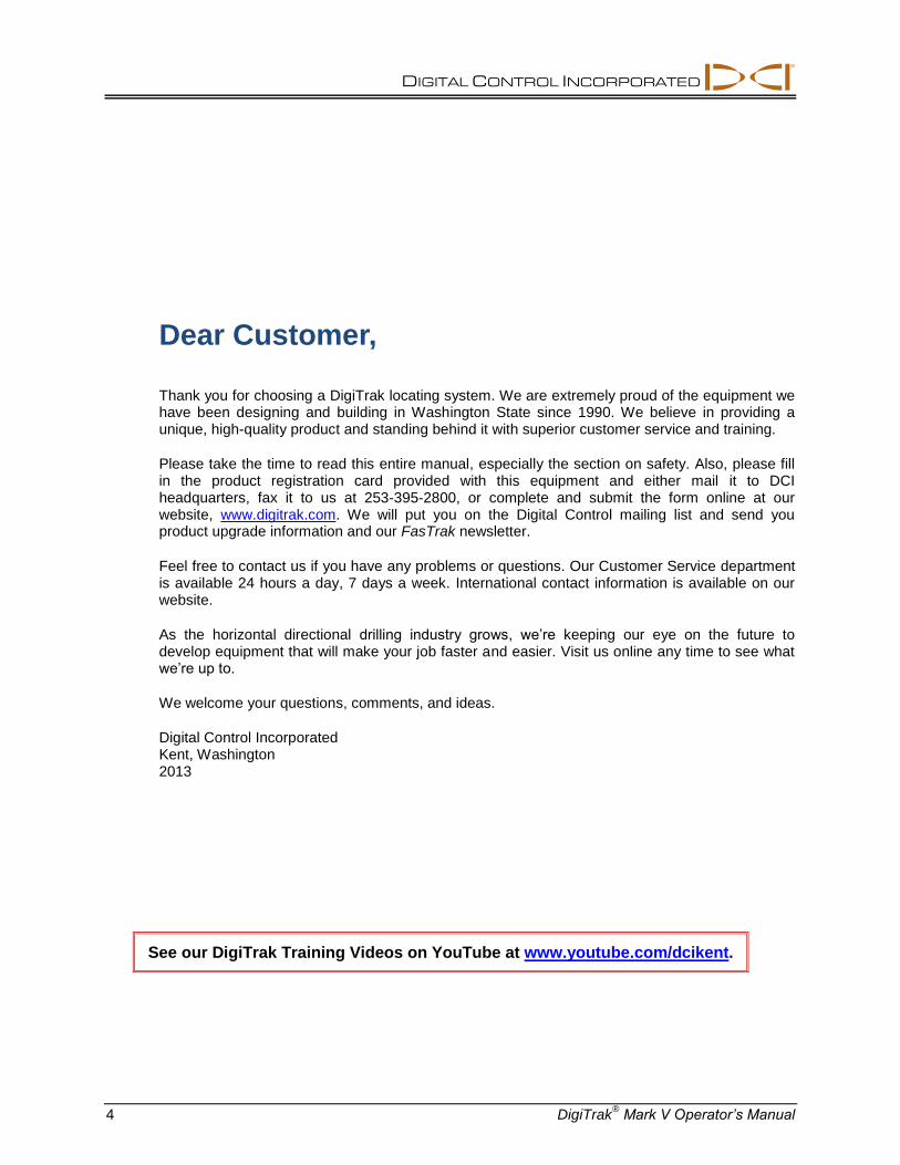
This display menu allows you to conduct a self-diagnostic test on the receiver. This test must be con-ducted in an interference-free area with no active transmitters within range.
1. Click the trigger to advance to the selftest menu. 2. Hold the trigger in through the countdown sequence from 2 to 0, and then release the trigger. 3. When the counter reaches 0, there will be a pause and then you will hear three confirmation beeps
and will see a checkmark at the bottom of the display, unless a fault is detected. If a fault is detected, you will see Err displayed along with an error code indicating the nature of the problem (for example, the 001 error code indicates that there is background noise or a transmitter is on). Before continuing, you must troubleshoot the problem or retest in a different area.
Selftest Menu Display Selftest Error Screen
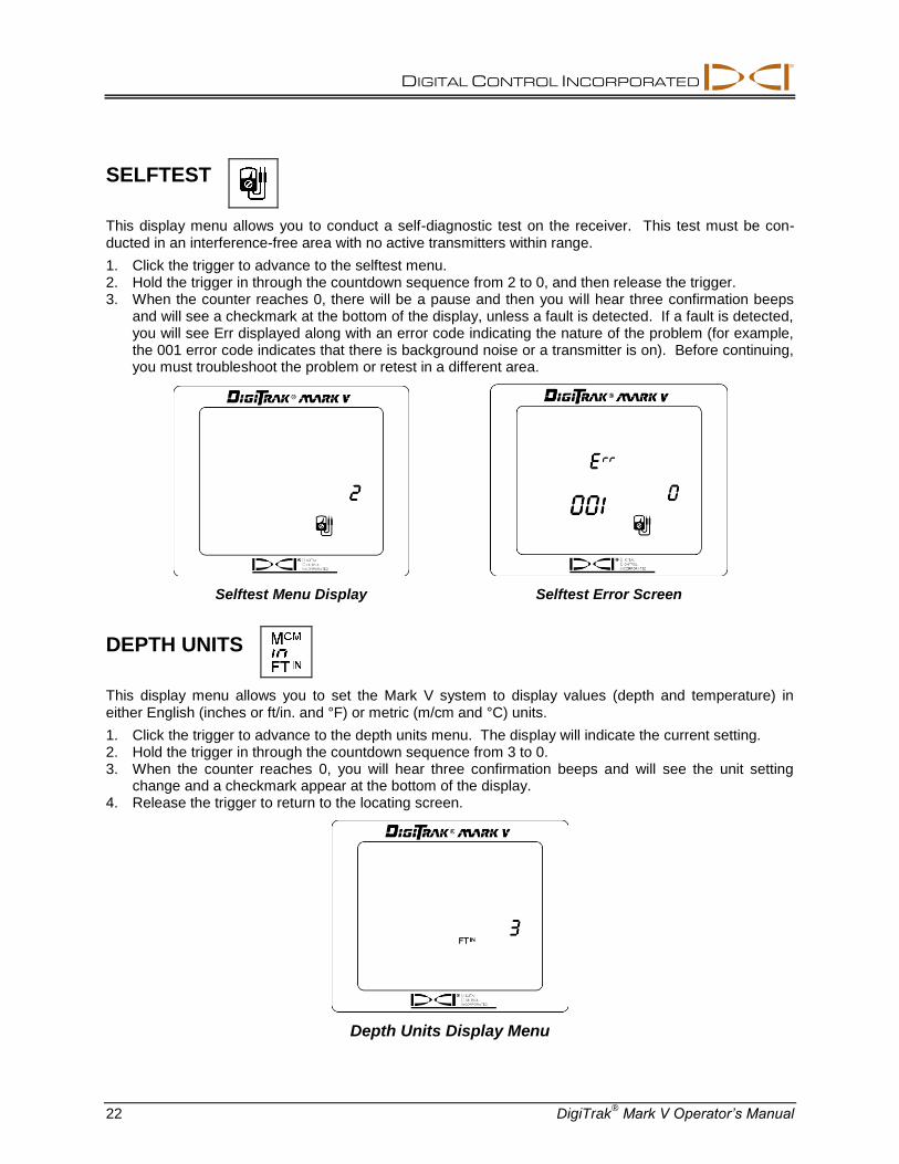
DEPTH UNITS
This display menu allows you to set the Mark V system to display values (depth and temperature) in either English (inches or ft/in. and °F) or metric (m/cm and °C) units.
1. Click the trigger to advance to the depth units menu. The display will indicate the current setting. 2. Hold the trigger in through the countdown sequence from 3 to 0. 3. When the counter reaches 0, you will hear three confirmation beeps and will see the unit setting
change and a checkmark appear at the bottom of the display. 4. Release the trigger to return to the locating screen.
Depth Units Display Menu

DIGITAL CONTROL INCORPORATED
DigiTrak® Mark V Operator’s Manual 23
PITCH UNITS
This display menu allows you to set the Mark V system to display pitch values in either degrees or percent of slope.
1. Click the trigger to advance to the pitch units menu. The display will indicate the current setting. 2. Hold the trigger in through the countdown sequence from 3 to 0. 3. When the counter reaches 0, you will hear three confirmation beeps and will see the unit setting
change and a checkmark appear at the bottom of the display. 4. Release the trigger to return to the locating screen.
Pitch Units Display Menu
HOUR METER
This display menu allows you to view the actual run time for the Mark V receiver.
1. Click the trigger to advance to the hour meter menu. 2. The hour meter will display the run time in hours, minutes, and seconds, and the hand on the clock
will be rotating to count down 5-second increments. (You do not need to hold the trigger in.) 3. The display will return to the locating screen when the trigger is clicked once.
Thousands
of Hours
Hours
Seconds
Minutes
Hour Meter Display
NOTE: The hour meter is useful when measuring transmitter lithium battery usage.

DIGITAL CONTROL INCORPORATED
24 DigiTrak® Mark V Operator’s Manual
Locating Instructions
Handling the Receiver
IMPORTANT NOTE: It is critical that you hold the receiver correctly to obtain accurate readings. You must hold the receiver level at all times and maintain a constant height-above-ground distance.
Marking Locate Positions
The front and rear locate points (FLP and RLP) and the locate line (LL) must be found and accurately marked during the locating procedure. To mark a locate position after you have found it, stand with the receiver level immediately above the locate point. Look down the vertical axis that runs through the center of the display to project a plumb line to the ground. The point where this plumb line hits the ground is the location that you should mark.
HINT: If you mark the FLP and the RLP, and then find the LL, you can determine the exact location of the transmitter/tool. It will be immediately below the point where the line connecting the FLP and the RLP intersects the LL. For complete information on the FLP, RLP, and LL, see the DigiTrak Mark III Directional Drilling Locating System Operator’s Manual.
Locating the Transmitter
With the DigiTrak Mark V, you can locate the transmitter/tool and its heading while it moves, whether standing in front of it, behind it, or toward the side. You can also locate the tool either facing toward or away from the drill rig.
The following technique guides you to the tool while standing out in front of it, facing the drill rig. This is the recommended method for locating. As you continue to drill or as the bore path curves, you may be facing the last marked locate point rather than the drill rig.
The first position to find is the front locate point or FLP. The FLP gives you the heading of the tool and the predicted tool depth. The FLP’s distance ahead of the tool is dependent upon the tool’s depth and
pitch; the deeper the tool, the further in front the FLP will be. The FLP is represented as a target on the receiver's display.
Center of Display
Vertical Axis
Place Marker Straight Down on Ground
Front of Receiver
Plumb Line
Plumb Line for Marking Locate Points

DIGITAL CONTROL INCORPORATED
DigiTrak® Mark V Operator’s Manual 25
Finding the FLP
1. Stand out in front of the tool (facing the drill) at a distance approximately 2 times the assumed depth. 2. Hold the trigger in for 1 second and release to lock in the signal, then begin walking toward the drill. 3. As you approach the FLP, the target appears in the top left corner of the display and the signal
strength increases.
Target in Top Left Corner Target Moving Toward the Box
4. Continue to walk forward until the target moves into the tracking icon (box). Note that the "+" sign changes to a "–", like it does with the Mark III system.
Target in the Box
5. Turn the receiver 90 to the tool’s direction, and again center the target in the box by moving the receiver forward or backward as needed. This is the FLP, which is where the tool will end up if it does not get a steering command.
6. With the target in the box, hold the trigger in for at least 1 second to lock in the signal. During this time, you will see the predicted depth (with an arrow pointing down to a target ahead of the transmitter) and the ultrasonic height. The predicted depth is the depth the tool will be at when it reaches this point (the FLP) if you do not give a steering command.

DIGITAL CONTROL INCORPORATED
26 DigiTrak® Mark V Operator’s Manual
Arrow pointing to target indicates the target is in the box and the receiver is above the FLP or the RLP. If there is not an arrow, then the reading is the slant distance to the transmitter.
Transmitter temperature replaces pitch reading when trigger is held in.
Predicted Depth Screen
7. Mark the location directly below the display screen as the FLP. 8. Release the trigger to return to the locating screen.
Finding the Tool and the LL
1. At the FLP, turn again to face the tool (and drill) and walk forward toward the last rod locate point. 2. Note that the LL appears in the top left of the display. 3. Walk forward and the LL moves closer to the box. 4. Center the LL in the box. Note that the "–" sign changes to a "+" sign, like it does with the Mark III
system.
LL Moving Toward the Box Line in the Box
5. Hold the trigger in to see the depth display. Note the ultrasonic setting to verify a correct height-above-ground measurement.
NOTE: The arrow that appears below the depth measurement and that points to the transmitter also appears on the remote display when a depth reading is taken.

DIGITAL CONTROL INCORPORATED
DigiTrak® Mark V Operator’s Manual 27
Arrow pointing to tool head indicates the line is in the box and the receiver is above the transmitter or the LL. If there is not an arrow, then the reading is the slant distance to the transmitter.
Transmitter temperature replaces pitch reading when trigger is held in.
Depth Screen
6. Mark this location as the LL. You should now be standing above the tool. 7. Release the trigger and you will briefly see the receiver frequency (see figure below) before the
display returns to the locating screen.
Receiver Frequency Display After Releasing Held Trigger
Confirmation of Exact Heading and Tool Position
Like the FLP, there is a point behind the transmitter called the rear locate point or RLP. When the FLP and RLP are connected, they make a line that represents the transmitter’s heading. Where this line intersects the LL is the position of the tool. Using the locate points and the LL to find the tool is more
reliable and efficient than using the peak signal. The RLP is represented as a target on the receiver's display.

DIGITAL CONTROL INCORPORATED
28 DigiTrak® Mark V Operator’s Manual
Finding the RLP
1. While standing above the tool still facing the drill, continue walking toward the drill; the target will appear in the top left corner of the display and the signal strength will decrease.
Target in Top Left Corner
2. Walk forward until the target moves into the box. Note that the "+" sign changes to a "–" sign, like it does with the Mark III system.
Target in the Box
3. Turn the receiver 90 to the tool’s direction and again put the target in the box by moving the receiver forward or backward as needed.
4. Mark this location as the RLP. 5. Connect the RLP to the FLP by a line. This line represents the transmitter/tool's heading. NOTE: If you hold the trigger in at the RLP, you will see a predicted depth reading. This depth is only valid at the FLP and must be ignored at the RLP. The receiver cannot discern between the RLP and the FLP.

DIGITAL CONTROL INCORPORATED
DigiTrak® Mark V Operator’s Manual 29
Remote Display
The Mark V remote display screen is configured in the same way as that on the receiver, and it uses the same display symbols. The remote display, however, has a main information screen and then only four menu options (power on/off, telemetry channel selection, backlight on/off, and hour meter). The main information screen is described below, and then the menu options are explained. Specific information on remote steering with the Mark V remote display and its use with a DataLog mapping system is also included.
Main Information Screen
The main information screen shown below is displayed when you turn on the Mark V remote display unit. The on/off button on the remote works similarly to the trigger on the receiver. The speaker on the remote warns the operator if the transmitter's temperature is increasing—temperature increases are accom-panied by tones from the speaker to indicate that appropriate and immediate attention is required. The speaker also emits tones during the DataLog function when a DataLog reading is received.
Front of Mark V Remote Display
The main information screen indicates when the receiver is over the transmitter or the locate line (LL), as shown below. The depth reading has an arrow below it pointing to the transmitter to indicate that the reading is the actual depth of the transmitter or LL rather than the slant distance. If there is not an arrow pointing down from the depth reading (as shown in the above graphic), then the distance is the slant distance.
Speaker
Remote Display Battery Status
On/Off
Button
Remote Steering Indicator
(with target in center) Roll/Pitch Indicator
(should be flashing)

DIGITAL CONTROL INCORPORATED
30 DigiTrak® Mark V Operator’s Manual
Arrow pointing to tool head indicates the line is in the box and the receiver is above the transmitter or the LL. If there is not an arrow, then the reading is the slant
distance to the transmitter.
Depth Reading When Receiver Is Above Transmitter or LL
By holding in the on/off button for 2 seconds or more, the receiver’s frequency setting will display in the bottom left and the transmitter temperature will display in place of the pitch information, as shown below.
Frequency and Temperature Reading with On/Off Button Held In
As shown below, the arrow below the depth reading is pointing to a target in front of the transmitter—this indicates that the receiver has the target in the box and is above the front or rear locate point (FLP or RLP). If the receiver is over the FLP, then the reading is the predicted depth. If there is not an arrow with the depth reading, then the distance is the slant distance to the transmitter.
Arrow pointing to target indicates the target is in the box and the receiver is above the FLP or the RLP. If there is not an arrow, then the reading is the slant distance to
the transmitter.
Up or down arrow indicates increasing or decreasing trend in transmitter
temperature.
Predicted Depth Reading When Receiver Is Above FLP or RLP

DIGITAL CONTROL INCORPORATED
DigiTrak® Mark V Operator’s Manual 31
Menu Options
The menu options are accessed in the same way as on the receiver. Click the on/off button to get to the menu screens, and then hold the button in for the countdown.
Power On/Off
With the power on/off menu displayed, as shown in the picture to the right, hold the button in for the countdown sequence from 3 to 0 to turn the unit off.
Telemetry Channel Selections
The telemetry channel menu, shown in the picture on the right, allows you to change the telemetry channel setting. Hold the button in to cycle through the four channel options (1, 2, 3, 4), and release when the desired setting is selected.
3
Backlight On/Off
At the backlight on/off menu option, shown in the picture on the right, hold the on/off button in to turn the display backlight on or off.
Hour Meter
The hour meter menu option displays the amount of time that the remote display unit has been running (turned on). In the picture on the right, the hour meter shows that the remote display unit has been running for 2,145 hours, 35 minutes, and 12 seconds. Click the on/off button once to exit the hour meter and return to the main information screen.

DIGITAL CONTROL INCORPORATED
32 DigiTrak® Mark V Operator’s Manual
Remote Steering Instructions
Instructions for using the Mark V system for remote steering are given below. Please refer first to "Remote Steering" under the Remote Display section in the DigiTrak Mark III Directional Drilling Locating System Operator’s Manual for instructions on how to set up the equipment.
Once the transmitter is lined up with the receiver, the arrow will appear below the depth reading and, when perfectly aligned, the target symbol in the center of the remote steering indicator will blink. If the tool gets off course, then the arrows to the left or right will start flashing, depending on the direction in which it has gone off course. The further the tool goes off course, then the further to the left or right of the target symbol the flashing arrows will be. For example, the arrow to the left of the target symbol will start blinking if the tool deviates to the left, and as it goes further to the left, then the arrows further to the left of the target symbol will be flashing.
Remote Steering Indicator
with Target in Center
Arrow pointing totool head indicatestransmitter is lined
up with receiver.
Display During Remote Steering When Transmitter Is Aligned with Receiver
DataLog Function
The DigiTrak Mark V remote display unit works differently when using the DataLog function than earlier DigiTrak remote displays. The correct procedure for taking a DataLog reading using the Mark V system is given below. Please also refer to the DataLog Operator's Manual.
1. Press the "Write" button on the DataLog module to place the unit in standby mode, which is indicated by a flashing LCD on the DataLog module.
2. At the Mark V receiver, record a DataLog reading (see instructions on page 9). 3. The remote display will sound three confirmation beeps when it receives the DataLog information,
and the LCD count on the DataLog module will be incremented by one.


DIGITAL
CONTROL
INCORPORATED
19625 62nd Ave S, Suite B103
Kent Washington 98032, USA
425.251.0559 / 800.288.3610
[email protected], www.DigiTrak.com
Page 1 of 2 DigiTrak® Mark V Operator’s Manual
LIMITED WARRANTY
Digital Control Incorporated ("DCI") warrants that when shipped from DCI each DCI Product will conform to DCI’s current published specifications in existence at the time of shipment and will be free, for the warranty period (“Warranty Period”) described below, from defects in materials and workmanship. The limited warranty described herein (“Limited Warranty”) is not transferable, shall extend only to the first end-user (“User”) purchasing the DCI Product from either DCI or a dealer expressly authorized by DCI to sell DCI Products (“Authorized DCI Dealer”), and is subject to the following terms, conditions and limitations:
1. A Warranty Period of twelve (12) months shall apply to the following new DCI Products: receivers/locators, remote displays, battery chargers and rechargeable batteries, and DataLog
® modules and interfaces. A Warranty Period of ninety
(90) days shall apply to all other new DCI Products, including transmitters, accessories, and software programs and modules. Unless otherwise stated by DCI, a Warranty Period of ninety (90) days shall apply to: (a) a used DCI Product sold either by DCI or by an Authorized DCI Dealer who has been expressly authorized by DCI to sell such used DCI Product; and (b) services provided by DCI, including testing, servicing, and repairing an out-of-warranty DCI Product. The Warranty Period shall begin from the later of: (i) the date of shipment of the DCI Product from DCI, or (ii) the date of shipment (or other delivery) of the DCI Product from an Authorized DCI Dealer to User.
2. DCI’s sole obligation under this Limited Warranty shall be limited to either repairing, replacing, or adjusting, at DCI’s option, a covered DCI Product that has been determined by DCI, after reasonable inspection, to be defective during the foregoing Warranty Period. All warranty inspections, repairs and adjustments must be performed either by DCI or by a warranty claim service authorized in writing by DCI. All warranty claims must include proof of purchase, including proof of purchase date, identifying the DCI Product by serial number.
3. The Limited Warranty shall only be effective if: (i) within fourteen (14) days of receipt of the DCI Product, User mails a fully completed Product Registration Card to DCI; (ii) User makes a reasonable inspection upon first receipt of the DCI Product and immediately notifies DCI of any apparent defect; and (iii) User complies with all of the Warranty Claim Procedures described below.
WHAT IS NOT COVERED
This Limited Warranty excludes all damage, including damage to any DCI Product, due to: failure to follow DCI’s operator’s manual and other DCI instructions; abuse; misuse; neglect; accident; fire; flood; Acts of God; improper applications; connection to incorrect line voltages and improper power sources; use of incorrect fuses; overheating; contact with high voltages or injurious substances; use of batteries or other products or components not manufactured or supplied by DCI; or other events beyond the control of DCI. This Limited Warranty does not apply to any equipment not manufactured or supplied by DCI nor, if applicable, to any damage or loss resulting from use of any DCI Product outside the designated country of use. By accepting a DCI Product and not returning it for a refund within thirty (30) days of purchase, User agrees to the terms of this Limited Warranty, including without limitation the Limitation of Remedies and Liability described below, and agrees to carefully evaluate the suitability of the DCI Product for User’s intended use and to thoroughly read and strictly follow all instructions supplied by DCI (including any updated DCI Product information which may be obtained at the above DCI website). In no event shall this Limited Warranty cover any damage arising during shipment of the DCI Product to or from DCI.
User agrees that the following will render the above Limited Warranty void: (i) alteration, removal or tampering with any serial number, identification, instructional, or sealing labels on the DCI Product, or (ii) any unauthorized disassembly, repair or modification of the DCI Product. In no event shall DCI be responsible for the cost of or any damage resulting from any changes, modifications, or repairs to the DCI Product not expressly authorized in writing by DCI, and DCI shall not be responsible for the loss of or damage to the DCI Product or any other equipment while in the possession of any service agency not authorized by DCI.
DCI reserves the right to make changes in design and improvements upon DCI Products from time to time, and User understands that DCI shall have no obligation to upgrade any previously manufactured DCI Product to include any such changes.

DIGITAL CONTROL INCORPORATED
DigiTrak® Mark V Operator’s Manual Page 2 of 2
THE FOREGOING LIMITED WARRANTY IS DCI’S SOLE WARRANTY AND IS MADE IN PLACE OF ALL OTHER WARRANTIES, EXPRESS OR IMPLIED, INCLUDING BUT NOT LIMITED TO THE IMPLIED WARRANTIES OF MERCHANTABILITY AND FITNESS FOR A PARTICULAR PURPOSE, IMPLIED WARRANTY OF NON-INFRINGEMENT, AND ANY IMPLIED WARRANTY ARISING FROM COURSE OF PERFORMANCE, COURSE OF DEALING, OR USAGE OF TRADE, ALL OF WHICH ARE HEREBY DISCLAIMED AND EXCLUDED. If DCI has substantially complied with the warranty claim procedures described below, such procedures shall constitute User’s sole and exclusive remedy for breach of the Limited Warranty.
LIMITATION OF REMEDIES AND LIABILITY
In no event shall DCI or anyone else involved in the creation, production, or delivery of the DCI Product be liable for any damages arising out of the use or inability to use the DCI Product, including but not limited to indirect, special, incidental, or consequential damages, or for any cover, loss of information, profit, revenue or use, based upon any claim by User for breach of warranty, breach of contract, negligence, strict liability, or any other legal theory, even if DCI has been advised of the possibility of such damages. In no event shall DCI’s liability exceed the amount User has paid for the DCI Product. To the extent that any applicable law does not allow the exclusion or limitation of incidental, consequential or similar damages, the foregoing limitations regarding such damages shall not apply.
This Limited Warranty gives you specific legal rights, and you may also have other rights which vary from state to state. This Limited Warranty shall be governed by the laws of the State of Washington.
WARRANTY CLAIM PROCEDURES
1. If you are having problems with your DCI Product, you must first contact the Authorized DCI Dealer where it was purchased. If you are unable to resolve the problem through your Authorized DCI Dealer, contact DCI’s Customer Service Department in Kent, Washington, USA at the above telephone number between 6:00 a.m. and 6:00 p.m. Pacific Time and ask to speak with a customer service representative. (The above “800” number is available for use only in the USA and Canada.) Prior to returning any DCI Product to DCI for service, you must obtain a Return Merchandise Authorization (RMA) number. Failure to obtain an RMA may result in delays or return to you of the DCI Product without repair.
2. After contacting a DCI customer service representative by telephone, the representative will attempt to assist you in troubleshooting while you are using the DCI Product during actual field operations. Please have all related equipment available together with a list of all DCI Product serial numbers. It is important that field troubleshooting be conducted because many problems do not result from a defective DCI Product, but instead are due to either operational errors or adverse conditions occurring in the User’s drilling environment.
3. If a DCI Product problem is confirmed as a result of field troubleshooting discussions with a DCI customer service representative, the representative will issue an RMA number authorizing the return of the DCI Product and will provide shipping directions. You will be responsible for all shipping costs, including any insurance. If, after receiving the DCI Product and performing diagnostic testing, DCI determines the problem is covered by the Limited Warranty, required repairs and/or adjustments will be made, and a properly functioning DCI Product will be promptly shipped to you. If the problem is not covered by the Limited Warranty, you will be informed of the reason and be provided an estimate of repair costs. If you authorize DCI to service or repair the DCI Product, the work will be promptly performed and the DCI Product will be shipped to you. You will be billed for any costs for testing, repairs and adjustments not covered by the Limited Warranty and for shipping costs. In most cases, repairs are accomplished within 1 to 2 weeks.
4. DCI has a limited supply of loaner equipment available. If loaner equipment is required by you and is available, DCI will attempt to ship loaner equipment to you by overnight delivery for your use while your equipment is being serviced by DCI. DCI will make reasonable efforts to minimize your downtime on warranty claims, limited by circumstances not within DCI’s control. If DCI provides you loaner equipment, your equipment must be received by DCI no later than the second business day after your receipt of loaner equipment. You must return the loaner equipment by overnight delivery for receipt by DCI no later than the second business day after your receipt of the repaired DCI Product. Any failure to meet these deadlines will result in a rental charge for use of the loaner equipment for each extra day the return of the loaner equipment to DCI is delayed.