maschiatori mgr msgr mtr mp100 ca - ober.it msgr mtr.pdf · cabezales de roscado ... se excluyen de...
TRANSCRIPT
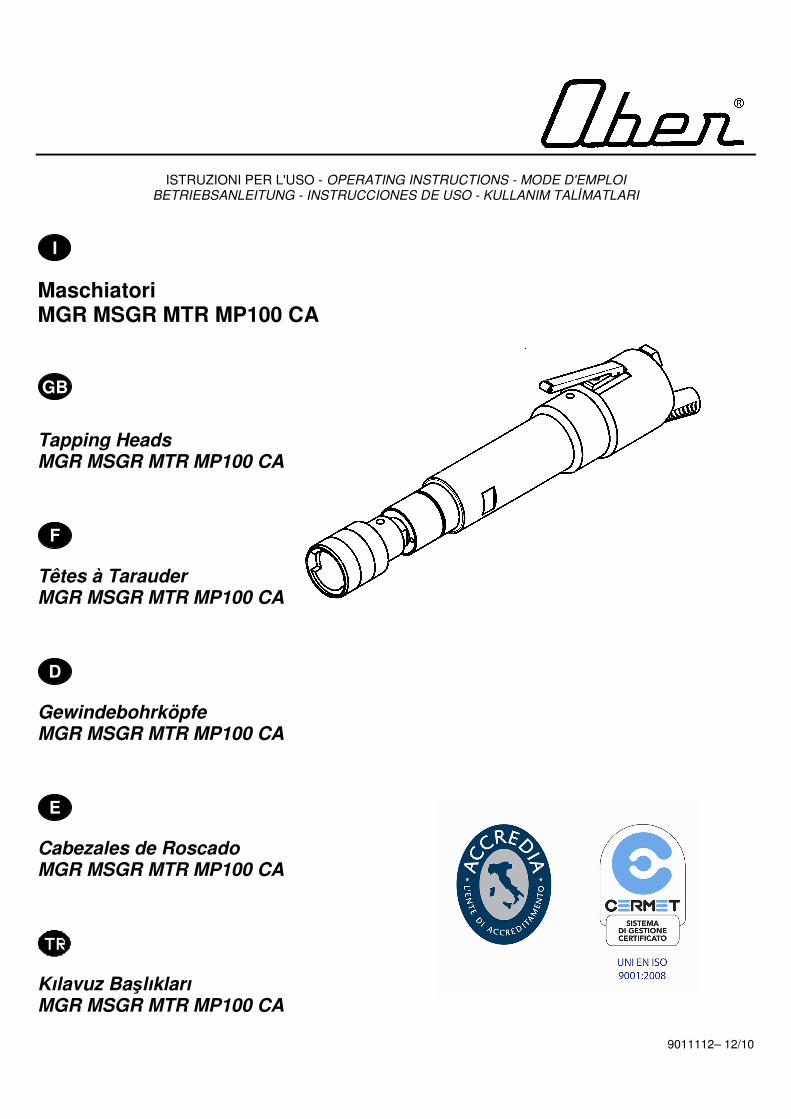
ISTRUZIONI PER L'USO - OPERATING INSTRUCTIONS - MODE D'EMPLOI BETRIEBSANLEITUNG - INSTRUCCIONES DE USO - KULLANIM TALİMATLARI
I
Maschiatori MGR MSGR MTR MP100 CA
GB
Tapping Heads MGR MSGR MTR MP100 CA
F
Têtes à Tarauder MGR MSGR MTR MP100 CA
D
Gewindebohrköpfe MGR MSGR MTR MP100 CA
E
Cabezales de Roscado MGR MSGR MTR MP100 CA
Kılavuz Başlıkları MGR MSGR MTR MP100 CA 9011112– 12/10

GARANZIA Ober S.p.A. garantisce i propri prodotti per un periodo di dodici mesi dalla data di acquisto e tale garanzia comprende la riparazione e la sostituzione delle parti che presentano difetti di lavorazione o vizi di materiale ed è riconosciuta solo ai prodotti inviati o presentati, ai Centri Assistenza Autorizzati, ai rivenditori o direttamente in Ober, completi e non manomessi, sono escluse le parti di ricambio singole danneggiate. Il prodotto deve essere accompagnato da un documento fiscale comprovante la data di acquisto (scontrino fiscale, fattura o bolla di consegna). Sono esclusi dalla garanzia i prodotti già riparati da persone non autorizzate, manomessi o modificati arbitrariamente ed inoltre gli eventuali danni derivanti da cattiva installazione, uso e manutenzione. Sono anche escluse dalla garanzia tutte le parti che presentano normale usura e quelle di ordinaria manutenzione. L’eventuale utilizzo di parti di ricambio non originali Ober possono danneggiare l’utensile o ridurne le prestazione e fa decadere il diritto di garanzia.
WARRANTY Ober S.p.A. guarantees its products for a period of twelve months from the data of purchase. The guarantee covers the repair and substitution of parts with machining or material defects. The guarantee is only valid if the products are dispatched or brought to an Authorised Assistance Centre, agent or Ober S.p.A. The products must not be tampered with and they must be complete. Damaged individual spare parts are not covered by the guarantee. The product must be accompanied by a document to prove the date of purchase (receipt, invoice or delivery note). Products that have been tampered with or repaired by unauthorised personnel are not covered by the guarantee. Damage caused by incorrect installation, use or maintenance is also excluded from the guarantee. Routine maintenance and normal wear are not covered by the guarantee. The use of spare parts other than original Ober ones can damage tools and reduce performance levels. Such action will also cause the guarantee to be declared null and void.
GARANTIE Ober S.p.A. garantit ses produits pour une période de douze mois à partir de la date d'achat ; cette garantie comprend la réparation et le remplacement des parties qui présentent des vices de fabrication ou des défauts de matériau et n'est reconnue que sur les produits envoyés ou apportés aux Centres d'Assistance Autorisés ou directement chez Ober, complets et inaltérés ; la garantie ne comprend pas les pièces détachées abîmées. Le produit doit être accompagné d'un document fiscal attestant la date d'achat (ticket de caisse, facture ou bulletin de livraison). La garantie ne comprend pas les produits déjà réparés par des personnes non autorisées, altérés ou modifiés de manière arbitraire ainsi que les dommages dus à des erreurs d'installation, d'utilisation et d'entretien. Sont également exclues de la garantie les pièces d'usure et celles qui doivent être régulièrement remplacées. L'emploi de pièces détachées non d'origine Ober peut endommager l'outil ou en limiter les performances et annule le droit de garantie.
GARANTIE Ober S.p.A. gewährt für die Produkte eigener Herstellung zwölf Monate Garantie ab Kaufdatum. Die Garantie umfasst die Reparatur bzw. den Austausch der Teile, die Verarbeitungs- oder Materialfehler aufweisen. Der Garantieanspruch gilt nur für Produkte, die vollständig und ohne unzulässigen Änderungen an autorisierte Kundendienststellen, an Händler oder direkt an Ober gesandt oder bei diesen eingereicht werden. Einzelne beschädigte Ersatzteile sind von der Garantie ausgeschlossen. Das Produkt muss stets von einem Kaufbeleg mit dem Kaufdatum begleitet sein (Kassenzettel, Rechnung oder Lieferschein). Von der Garantie ausgeschlossen sind bereits von nicht befugten Personen reparierte und geänderte Produkte sowie Schäden infolge von unsachgemässer Montage, Verwendung und Wartung. Von der Garantie ausgeschlossen sind ferner Verschleissteile und Teile, die für die normale Instandhaltung erforderlich sind. Die Verwendung von nicht originalen Ersatzteilen kann zur Beschädigung des Werkzeugs führen bzw. dessen Leistung mindern und führt zum Verfall der Garantie.
GARANTÍA Ober S.p.A. garantiza sus propios productos por un periodo de doce meses a partir de la fecha de compra y dicha garantía incluye la reparación y la sustitución de las partes que presentan fallas de fabricación o defectos del material y se reconoce sólo a los productos que se envíen o presenten, en los Centros de Asistencia Autorizados, a los revendedores o directamente a Ober, completos y que no estén forzados, se excluyen las piezas de repuesto separadas y estropeadas. El producto debe estar acompañado por un documento fiscal que compruebe la fecha de compra (recibo fiscal, factura o albarán). Se excluyen de la garantía los productos ya reparados por personal no autorizado, alterados o modificados arbitrariamente y además los posibles daños provocados por instalación, uso y mantenimiento inadecuados. Se excluyen también de la garantía todas las piezas que presentan normal desgaste y las de mantenimiento ordinario. El uso eventual de piezas de repuesto no originales Ober puede provocar daños a la herramienta o reducir su prestación y en tal caso caduca el derecho de garantía.

GARANTİ Ober S.p.A., ürünleri, satın alınma tarihinden itibaren on iki ay süreyle garanti kapsamındadır. Bu garanti, çalışma mekanizması veya malzeme kusurlarının onarılmasını ve bozuk parçaların değiştirilmesini kapsar. Bu garanti, sadece Yetkili Yardım Merkezi, bayiler veya Ober S.p.A. tarafından gönderilmiş veya buralardan satın alınmış ürünler için geçerlidir. Bu ürünler değiştirilmemeli ve eksiksiz olmalıdır. Hasarlı tüm yedek parçaların değişimi garanti kapsamında değildir.
Ürün ile birlikte satın alım tarihini ispatlayan bir belge (makbuz, fatura veya sevk irsaliyesi) ibraz edilmelidir. Üzerinde değişiklik yapılan veya yetkili olmayan personel tarafından onarılan ürünler, garanti kapsamında değildir. Ayrıca, hatalı montaj, kullanım veya bakımdan kaynaklanan hasarlar da garanti kapsamı dışındadır. Rutin bakım ve normal yıpranma, garanti kapsamı dışındadır. Orijinal Ober yedek parçalarından farklı yedek parçaların kullanılması, araçlara hasar verebilir ve performans seviyelerini düşürebilir. Bu tür işlemler sonucunda da garanti geçersiz olacaktır.


1
I L’operatore dovrà avere letto attentamente e compreso le presenti istruzioni, prima di utilizzare la macchina. La macchina, i collegamenti e gli accessori devono essere impiegati esclusivamente per lo scopo espressamente indicato. Qualsiasi modifica alla macchina ed ai suoi accessori deve essere espressamente autorizzata dall’ufficio tecnico della ditta costruttrice. Prima di eseguire qualsiasi operazione di manutenzione, registrazione, o non rientrante nel normale
ciclo di funzionamento, escludere il collegamento alla rete di alimentazione. GB
The operator must read and fully understand these instructions before using the machine. The machine, connections and accessories must only be used for the purpose specified. Any adjustments to the motor and accessories must only be done after permission has been granted from the manufacturer's technical department. The mains supply must be disconnected before any maintenance, adjustments or non-standard
functioning cycles are undertaken.
F Avant d'utiliser la machine, l'opérateur doit avoir lu avec attention les présentes instructions et les avoir assimilées. La machine, les branchements et les accessoires ne doivent être utilisés que pour le but expressément indiqué. Toute modification apportée à la machine et à ses accessoires doit être expressément autorisée par le bureau technique du fabricant.
Avant d'effectuer toutes opérations d’entretien et de réglage ou des opérations non comprises dans le cycle de fonctionnement normal, débrancher le réseau d'alimentation.
D Der Benutzer muss vor Verwendung des Geräts diese Anleitung aufmerksam gelesen und verstanden haben. Das Gerät, die Anschlüsse und das Zubehör dürfen nur für den ausdrücklich angegebenen Zweck verwendet werden. Änderungen am Gerät und dessen Zubehör erfordern einer ausdrücklichen Genehmigung durch die technische Abteilung der Herstellerfirma.
Vor allen Wartungsarbeiten, Einstellungen bzw. sonstigen Arbeiten, die nicht zum normalen Betriebszyklus zählen, muss der Anschluss an das Versorgungsnetz unterbrochen werden.
E
EI operador tendrá que leer atentamente y entender las presentes instrucciones antes de utilizar esta máquina. La máquina, las conexiones y los accesorios se deben emplear exclusivamente para el fin específico indicado. Cualquier modificación de la máquina y de sus accesorios debe estar especialmente autorizada por el Departamento Técnico de la empresa fabricante. Antes de efectuar cualquier operación de mantenimiento, regulación, o que no esté incluida en et ciclo de
funcionamiento normal, desconectar la conexión a la red de alimentación.
Operatör, motoru kullanmadan önce bu talimatları okumalı ve tamamen anlamalıdır. Motor, bağlantılar ve aksesuarlar sadece belirlenen amaç için kullanılmalıdır. Motor ve aksesuarlarda yapılacak herhangi bir ayarlama, üretici firmanın teknik departmanının onayı alındıktan sonra yapılmalıdır. Herhangi bir bakım, ayarlama veya standart dışı çalışma yapılmadan önce motorun ana şebekeyle olan bağlantısı kesilmelidir.

2
INDICE I Parti principali ................................................................................................................................................... pag. 3 Caratteristiche tecniche .................................................................................................................................... pag. 5 Alimentazione ................................................................................................................................................... pag. 11 Utilizzo .............................................................................................................................................................. pag. 16 Manutenzione ................................................................................................................................................... pag. 24 Accessori .......................................................................................................................................................... pag. 28
CONTENTS GB Main components................................................................................................................................................ pg. 4 Technical features............................................................................................................................................... pg. 6 Compressed air supply system........................................................................................................................... pg. 12 Use...................................................................................................................................................................... pg. 17 Maintenance ....................................................................................................................................................... pg. 25 Accessories......................................................................................................................................................... pg. 28
INDEX F Parties principales............................................................................................................................................ page 4 Caractéristiques techniques ............................................................................................................................ page 7 Alimentation ..................................................................................................................................................... page 12 Utilisation ......................................................................................................................................................... page 17 Entretien........................................................................................................................................................... page 25 Accessoires...................................................................................................................................................... page 28
INHALTSVERZEICHNIS D Hauptteile.............................................................................................................................................................. s. 4 Technische Eigenschaften.................................................................................................................................... s. 8 Druckluftanschluss................................................................................................................................................ s. 12 Anwendung ........................................................................................................................................................... s. 17 Wartung ................................................................................................................................................................ s. 25 Zubehör................................................................................................................................................................. s. 28
ÍNDICE E Partes principales ............................................................................................................................................. pág. 4 Características técnicas.................................................................................................................................... pág. 9 Alimentación ..................................................................................................................................................... pág. 13 Uso.................................................................................................................................................................... pág. 18 Mantenimiento .................................................................................................................................................. pág. 26 Accesorios ........................................................................................................................................................ pág. 28
İÇİNDEKİLER Ana Bileşenler................................................................................................................................................. sayfa 4 Teknik özellikler .............................................................................................................................................. sayfa 10 Basınçlı hava besleme sistemi ...................................................................................................................... sayfa 13 Kullanım .......................................................................................................................................................... sayfa 18 Bakım.............................................................................................................................................................. sayfa 26 Aksesuarlar ..................................................................................................................................................... sayfa 28

3
PARTI PRINCIPALI I A).......................................................................................................................................................................Mandrino B)........................................................................................................................................................... Gruppo riduttore C) ................................................................................................................................................ Corpo esterno utensile D) ......................................................................................................................................................Leva di avviamento E)...................................................................................................................................... Pulsante inversione rotazione F)...................................................................................................................................................................Silenziatore G) ...............................................................................................................................................Attacco aria compressa Fig.1
Modello L (mm) P (mm) ØM (mm) ØN (mm) ØR (mm) MGR33-55-77 272 60 33.5 43 40 MSGR33-55 297 60 33.5 43.5 40 MTR11 479 96.5 51 54 60 MTR44-66 444 96.5 51 54 48 MTR88 460 96.5 51 54 60 MTR115 418 96.5 51 54 48 MP100 CA 489 96.5 51 50 58

4
MAIN COMPONENTS GB A)............................................................................................................................................................................Chuck B)...............................................................................................................................................................Reduction unit C) .....................................................................................................................................................................Tool body D) ................................................................................................................................................................Starting lever E)................................................................................................................................................ Reverse rotation button F).........................................................................................................................................................................Silencer G) ....................................................................................................................................................Compressed air inlet
PARTIES PRINCIPALES F A).........................................................................................................................................................................Mandrin B)......................................................................................................................................................... Groupe réducteur C) ..............................................................................................................................................Corps extérieur de l'outil D) ............................................................................................................................................. Bouton de mise en route E)........................................................................................................................ Bouton d’inversion du sens de rotation F)..................................................................................................................................................................... Silencieux G) ................................................................................................................................Orifice alimentation air comprimé
HAUPTTEILE D A)......................................................................................................................................................................Bohrfutter B)................................................................................................................................................. Untersetzungsgetriebe C) .......................................................................................................................................................Werkzeuggehäuse D) ........................................................................................................................................................................Schalter E)..........................................................................................................................................................Umschaltenknopf F)...............................................................................................................................................................Schalldämpfer G) ...................................................................................................................................................... Druckluftanschluss
PARTES PRINCIPALES E A)..........................................................................................................................................................................Mandril B)............................................................................................................................................................. Grupo reductor C) ...............................................................................................................................Cuerpo exterior de la herramienta D) ..........................................................................................................................................Leva de puesta en marcha E).......................................................................................................................... Interruptor de inversíon de la marcha F)....................................................................................................................................................................Silenciador G) .....................................................................................................................................Conexión del aire comprimido
ANA BİLEŞENLER A)..................................................................................................................................................................Torna kafası B)....................................................................................................................................................... Redüksiyon ünitesi C) .............................................................................................................................................................Çalıştırma kolu D) ................................................................................................................................................................. Alet gövdesi E)...............................................................................................................................................Ters döndürme düğmesi F)......................................................................................................................................................................Susturucu G) .......................................................................................................................................................Basınçlı hava girişi

5
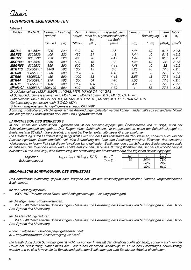
CARATTERISTICHE TECNICHE I Tabella 1
Modello Codice Velocità a vuoto
Potenza Consumo Coppia a 6 bar
Capacità di maschiatura su acciaio
Peso Ø fissaggio
Rumorosità Lp
Vibrazioni ah
(giri/min.) (W) (Nl/min.) (Nm) (mm) (Kg) (mm) (dB(A)) (m/s2)
MGR33 8305528 720 220 430 12 2-5 1.44 40 81.6 < 2.5 MGR55 8305529 400 220 430 21 4-8 1.44 40 81.6 < 2.5 MGR77 8305530 220 220 430 28 4-12 1.44 40 81.6 < 2.5 MSGR33 8305531 650 300 600 16 3-8 1.48 40 82 < 2.5 MSGR55 8305532 350 300 600 30 4-14 1.48 40 82 < 2.5 MTR115 8305527.1 1400 500 1000 13 3-8 3.25 48 77.8 < 2.5 MTR88 8305522.1 600 500 1000 28 4-12 3.9 60 77.8 < 2.5 MTR66 8305525.1 450 500 1000 38 4-16 3.55 48 77.8 < 2.5 MTR44 8305524.1 270 500 1000 64 4-16 3.55 48 77.8 < 2.5 MTR11 8305526.1 100 500 1000 180 6-30 4.2 60 77.8 < 2.5 MP100 CA 8305537.1 300/100 600 800 180 6-30 4 58 77.8 < 2.5 Attacco aria MGR, MSGR 1/4” GAS; MTR, MP100 CA 1/2" GAS Ø int. tubo min. MGR 8 mm, MSGR 10 mm, MTR, MP100 CA 13 mm Attacco mandrino MGR, MSGR, MTR44, MTR66, MTR115: B12; MTR88, MTR11, MP100 CA: B16 Livello di rumorosità determinato secondo ISO/CD 15744 Livello di vibrazioni all’impugnatura determinato secondo ISO 8662
Avvertenza: verificare che le prestazioni richieste rientrino nel campo di quelle disponibili, in caso contrario occorrerà scegliere un modello diverso nell'ampia gamma proposta da OBER. RUMOROSITÀ DELL’UTENSILE La tabella delle caratteristiche tecniche riporta il livello di pressione sonora (e di potenza acustica, nel caso in cui questo superi gli 85 db(A)). Le protezioni per l’udito devono essere utilizzate qualora il livello di pressione sonora in posizione operatore superi gli 85 dB(A) e sono consigliate per valori inferiori a tale soglia. Il rischio rumore è legato, oltre che all’intensità della sorgente, anche al tempo di esposizione ed è quindi opportuno valutare l’impiego del singolo utensile nel corso della giornata lavorativa ed attenersi alle disposizioni vigenti nei singoli Paesi al fine di salvaguardare gli utilizzatori. La formula e la tabella seguenti consentono di apprezzare l’influenza del tempo di utilizzo sul livello di esposizione giornaliera, grazie al coefficiente di impiego c, che per i maschiatori è compreso tra il 20 ed il 40%.
Leq,d = Leq + 10 Log10 Te/ T0
VIBRAZIONI DELL’UTENSILE L’utensile in oggetto, provato nel rispetto delle condizioni imposte dalle norme tecniche di riferimento per la pressione di alimentazione: • ISO 2787 (Rotary and percussive pneumatic tools – performance tests) per le indicazioni generali di prova: • ISO 8662 (Hand-held portable power tools – Measurement of vibration at the handle) recepita dalla UNI EN 28662 per i fattori di ponderazione: • ISO 5349 (Mechanical vibration - Guidelines for the measurements and the assessments of human exposure to hand-trasmitted vibration
è caratterizzato dal seguente livello di vibrazioni:
ah = accelerazione ponderata in frequenza <2.5m/s2
Il rischio vibrazioni è legato, oltre che all’intensità della sorgente, anche al tempo di esposizione ed è quindi opportuno valutare l’impiego del singolo utensile nel corso della giornata lavorativa ed attenersi alle disposizioni vigenti nei singoli Paesi al fine di salvaguardare gli utilizzatori.
Te= c T0 T0 = 8h
Livello esposizione giornaliera
Leq c Leq,d
85 20% 30% 40%
78,0 79,8 81,0

6
TECHNICAL FEATURES GB Table 1
Model Code No-load speed
Power Consumption
Torque at 6 bar
Steel threading
Weight
Ø fitting Noise Lp
Vibrations ah
(rpm) (W) (Nl/min.) (Nm) (mm) (Kg) (mm) (dB(A)) (m/s2)
MGR33 8305528 720 220 430 12 2-5 1.44 40 81.6 < 2.5 MGR55 8305529 400 220 430 21 4-8 1.44 40 81.6 < 2.5 MGR77 8305530 220 220 430 28 4-12 1.44 40 81.6 < 2.5 MSGR33 8305531 650 300 600 16 3-8 1.48 40 82 < 2.5 MSGR55 8305532 350 300 600 30 4-14 1.48 40 82 < 2.5 MTR115 8305527.1 1400 500 1000 13 3-8 3.25 48 77.8 < 2.5 MTR88 8305522.1 600 500 1000 28 4-12 3.9 60 77.8 < 2.5 MTR66 8305525.1 450 500 1000 38 4-16 3.55 48 77.8 < 2.5 MTR44 8305524.1 270 500 1000 64 4-16 3.55 48 77.8 < 2.5 MTR11 8305526.1 100 500 1000 180 6-30 4.2 60 77.8 < 2.5 MP100 CA 8305537.1 300/100 600 800 180 6-30 4 58 77.8 < 2.5 Air inlet MGR, MSGR 1/4” GAS; MTR, MP100 CA 1/2" GAS Ø inside tube min. MGR 8 mm, MSGR 10 mm, MTR, MP100 CA 13 mm Fitting chuck MGR, MSGR, MTR44, MTR66, MTR115: B12; MTR88, MTR11, MP100 CA: B16 Noise emission levels determined by using ISO/CD 15744 Levels of vibrations at the handle determined by using ISO 8662
Note: make sure that the performance features required correspond to those described above, otherwise it will be necessary to choose a different model from the broad range offered by OBER. TOOL NOISE The table of technical specifications indicates the noise level- where the noise level exceeds 85 dB (A) the noise power is also indicated. Ear protectors must be worn where the noise level exceeds 85 dB (A) at the operator position. We recommend that you also wear ear protectors below this noise level. Noise risk and hearing damage are related to the intensity of the noise source and the length of exposure. Noise risk must be assessed on a case by case basis taking into account these two factors. Measures should be taken to protect the user against hearing damage in accordance with current Health and Safety regulations. The formula and table can be used to calculate the daily exposure level for a tool using the use coefficient c. The use coefficient c for a tapping head is between 20 and 40%.
Leq,d = Leq + 10 Log10 Te/ T0
TOOL VIBRATION The tool in question, tested with regard to the conditions required by the relevant technical standards for feed pressure: • ISO 2787 (Rotary and percussive pneumatic tools - performance tests) for general test indications:
• ISO 5349 (Mechanical vibration - Guidelines for the measurements and the assessments of human exposure to hand-transmitted vibration for weighting factors:
• ISO 5349 (Mechanical vibration - Guidelines for the measurements and the assessments of human exposure to hand-transmitted vibration
characterised by the following level of vibrations:
ah = frequency-weighted acceleration <2.5m/s2
The risk from vibrations is linked not only to the intensity of the source, but also to the exposure time and it is therefore advisable to evaluate the use of the individual tool during the working day and stick to the regulations in force in individual countries in order to protect users.
Te= c T0 T0 = 8h
Leq c Leq,d
85 20% 30% 40%
78,0 79,8 81,0
Dally exposure level

7
CARACTERISTIQUES TECHNIQUES F Tableau 1
Modèle Code Vitesse à vide
Puissance Consom-mation
Couple à 6 bar
Capacité de tauraudage
sur acier
Poids Ø fissage
Bruit Lp
Vibration ah
(tou/min) (W) (Nl/min.) (Nm) (mm) (Kg) (mm) (dB(A)) (m/s2)
MGR33 8305528 720 220 430 12 2-5 1.44 40 81.6 < 2.5 MGR55 8305529 400 220 430 21 4-8 1.44 40 81.6 < 2.5 MGR77 8305530 220 220 430 28 4-12 1.44 40 81.6 < 2.5 MSGR33 8305531 650 300 600 16 3-8 1.48 40 82 < 2.5 MSGR55 8305532 350 300 600 30 4-14 1.48 40 82 < 2.5 MTR115 8305527.1 1400 500 1000 13 3-8 3.25 48 77.8 < 2.5 MTR88 8305522.1 600 500 1000 28 4-12 3.9 60 77.8 < 2.5 MTR66 8305525.1 450 500 1000 38 4-16 3.55 48 77.8 < 2.5 MTR44 8305524.1 270 500 1000 64 4-16 3.55 48 77.8 < 2.5 MTR11 8305526.1 100 500 1000 180 6-30 4.2 60 77.8 < 2.5 MP100 CA 8305537.1 300/100 600 800 180 6-30 4 58 77.8 < 2.5 Orifice alim.air MGR, MSGR 1/4” GAS; MTR, MP100 CA 1/2" GAS Ø int. tube min. MGR, 8 mm, MSGR 10 mm, MTR, MP100 CA 13 mm Fixation mandrin MGR, MSGR, MTR44, MTR66, MTR115: B12; MTR88, MTR11, MP100 CA: B16 Niveau sonore déterminé selon les normes ISO/CD 15744 Niveau des vibrations sur la poigneé déterminé selon les normes ISO 8662
Attention: vérifiez que les caracteristiques requises correspondent aux possibilites de l’outil; sinon il conviendra de choisir un modèle différent parmi tous ceux de la gamme OBER. BRUIT DE L'OUTIL Le tableau des caractéristiques techniques indique le niveau de pression sonore (et de puissance acoustique, si celle-ci dépasse les 85 db(A)). Les protections pour l'appareil auditif doivent être utilisées lorsque le niveau de pression sonore sur le poste de l'opérateur dépasse les 85 dB(A) et elles sont recommandées pour des valeurs inférieures à ce seuil. Le risque sonore est lié, outre à l'intensité de la source, à la durée d’exposition. Il convient donc d’évaluer l'utilisation de chaque outil dans la journée de travail et de respecter les dispositions en vigueur dans les différents pays afin de protéger les utilisateurs. La formule et les tableaux suivants permettent d’apprécier l'influence de la durée d'utilisation sur le niveau d'exposition quotidienne, grâce au coefficient d'utilisation c, qui, pour les têtes à tarauter, est compris entre 20 et 40%.
Leq,d = Leq + 10 Log10 Te/ T0
VIBRATIONS DE L'OUTIL
Le présent outil, testé conformément aux conditions prescrites par les normes techniques de référence pour la pression d’alimentation:
• ISO 2787 (Outils pneumatiques rotatifs et à percussion – essais de performances) pour les indications générales d’essai:
• ISO 5349 (Vibrations mécaniques – Directives pour la mesure et l’évaluation de l’exposition de l’homme à des vibrations transmises par les mains) pour les facteurs de pondération:
• ISO 5349 (Vibrations mécaniques – Directives pour la mesure et l’évaluation de l’exposition de l’homme à des vibrations transmises par les mains) présente le niveau de vibrations suivant: ah = accélération pondérée en fréquence <2,5m/s2 Le risque de vibrations est lié à l’intensité de la source ainsi qu’au temps d’exposition. Il est donc opportun d’évaluer l’utilisation de l’outil durant la journée de travail et de respecter les dispositions en vigueur dans les différents pays pour la protection des utilisateurs.
Te= c T0 T0 = 8h
Niveau d'exposition Journalière
Leq c Leq,d
85 20% 30% 40%
78,0 79,8 81,0
8
TECHNISCHE EIGENSCHAFTEN D Tabelle 1
Modell Kode-Nr. Leerlauf-drehzal
Leistung Ver-brauch
Drehmo-ment bei 6
bar
Kapazität beim gewindeschneiden
auf Stahl
Gewicht Ø Befestigung
Lärm Lp
Vibrat. ah
(U/min.) (W) (Nl/min.) (Nm) (mm) (Kg) (mm) (dB(A)) (m/s2)
MGR33 8305528 720 220 430 12 2-5 1.44 40 81.6 < 2.5 MGR55 8305529 400 220 430 21 4-8 1.44 40 81.6 < 2.5 MGR77 8305530 220 220 430 28 4-12 1.44 40 81.6 < 2.5 MSGR33 8305531 650 300 600 16 3-8 1.48 40 82 < 2.5 MSGR55 8305532 350 300 600 30 4-14 1.48 40 82 < 2.5 MTR115 8305527.1 1400 500 1000 13 3-8 3.25 48 77.8 < 2.5 MTR88 8305522.1 600 500 1000 28 4-12 3.9 60 77.8 < 2.5 MTR66 8305525.1 450 500 1000 38 4-16 3.55 48 77.8 < 2.5 MTR44 8305524.1 270 500 1000 64 4-16 3.55 48 77.8 < 2.5 MTR11 8305526.1 100 500 1000 180 6-30 4.2 60 77.8 < 2.5 MP100 CA 8305537.1 300/100 600 800 180 6-30 4 58 77.8 < 2.5 Druckluftanschluss MGR, MSGR 1/4” GAS; MTR, MP100 CA 1/2" GAS Ø Schlauchdurchmesser innen min. MGR 8 mm, MSGR 10 mm, MTR, MP100 CA 13 mm Futterwechsel MGR, MSGR, MTR44, MTR66, MTR115: B12; MTR88, MTR11, MP100 CA: B16 Geräuschpegel gemessen nach ISO/CD 15744 Schwingungspegel am Handgriff gemessen nach ISO 8662
Achtung: Kontrollieren, ob die gewünschten Anwendungen geleistet werden können, andernfalls soll ein anderes Modell aus der grossen Produktpalette der Firma OBER gewählt werden. LARMEMISSION DES WERKZEUGS In der Tabelle der Technischen Eigenschaften ist der Schalldruckpegel (bei Überschreiten von 85 dB(A) auch der Schalleistungspegel) angegeben. Das Tragen eines Gehörschutzes ist vorgeschrieben, wenn der Schalldruckpegel am Bedienerstand 85 dB(A) überschreitet, und wird bei Werten unterhalb dieser Grenze empfohlen. Die Gefährdung durch Lärmbelastung hängt nicht allein von der Emissionsstärke an der Quelle ab, sondern auch von der Aussetzungsdauer. Daher empfiehlt sich eine Beurteilung des über den Arbeitstag verteilten Einsatzes des einzelnen Werkzeuges. In jedem Fall sind die im jeweiligen Land geltenden Bestimmungen zum Schutz des Bedienungspersonals einzuhalten. Die folgende Formel und Tabelle ermöglichen, dank des Nutzungskoeffizienten, der bei Gewindebohrköpfe zwischen 20 und 40% liegt, eine Beurteilung der Auswirkung der Einsatzdauer auf den täglichen Belastungspegel.
Leq,d = Leq + 10 Log10 Te/ T0
MECHANISCHE SCHWINGUNGEN DES WERKZEUGS Das betreffende Werkzeug, geprüft nach Vorgabe der von den einschlägigen technischen Normen vorgeschriebenen Bedingungen für den Versorgungsdruck:
• ISO 2787 (Pneumatische Druck- und Schlagwerkzeuge - Leistungsprüfungen) für die allgemeinen Prüfanweisungen:
• ISO 5349 (Mechanische Schwingungen - Messung und Bewertung der Einwirkung von Schwingungen auf das Hand-Arm-System des Menschen) für die Gewichtungsfaktoren:
• ISO 5349 (Mechanische Schwingungen - Messung und Bewertung der Einwirkung von Schwingungen auf das Hand-Arm-System des Menschen) ist durch folgenden Vibrationspegel gekennzeichnet: ah = frequenzbewertete Beschleunigung <2,5m/s2
Die Gefährdung durch Schwingungen ist nicht nur von der Intensität der Vibrationsquelle abhängig, sondern auch von der Dauer der Aussetzung. Daher muss der Einsatz des einzelnen Werkzeugs im Laufe des Arbeitstages berücksichtigt werden und es sind jeweils die im Einsatzland geltenden Bestimmungen zum Schutz der Arbeiter einzuhalten.
Leq c Leq,d
85 20% 30% 40%
78,0 79,8 81,0
e= c T0 T0 = 8h
Täglicher Belastungspegel

9
CARACTERISTICAS TECNICAS E Tabla 1
Modelo Còdigo Velocidad en vacío
Potencia Consumo Par a 6 bar
Capacidad de roscado sobre acero
Peso Ø fijación
Ruidos Lp
Vibraciones ah
(r.p.m.) (W) (Nl/min.) (Nm) (mm) (Kg) (mm) (dB(A)) (m/s2)
MGR33 8305528 720 220 430 12 2-5 1.44 40 81.6 < 2.5 MGR55 8305529 400 220 430 21 4-8 1.44 40 81.6 < 2.5 MGR77 8305530 220 220 430 28 4-12 1.44 40 81.6 < 2.5 MSGR33 8305531 650 300 600 16 3-8 1.48 40 82 < 2.5 MSGR55 8305532 350 300 600 30 4-14 1.48 40 82 < 2.5 MTR115 8305527.1 1400 500 1000 13 3-8 3.25 48 77.8 < 2.5 MTR88 8305522.1 600 500 1000 28 4-12 3.9 60 77.8 < 2.5 MTR66 8305525.1 450 500 1000 38 4-16 3.55 48 77.8 < 2.5 MTR44 8305524.1 270 500 1000 64 4-16 3.55 48 77.8 < 2.5 MTR11 8305526.1 100 500 1000 180 6-30 4.2 60 77.8 < 2.5 MP100 CA 8305537.1 300/100 600 800 180 6-30 4 58 77.8 < 2.5 Conexión aire MGR, MSGR 1/4” GAS; MTR, MP100 CA 1/2" GAS Ø int. tubo min. MGR 8 mm, MSGR 10 mm, MTR, MP100 CA 13 mm Fijación mandril: MGR, MSGR, MTR44, MTR66, MTR115: B12; MTR88, MTR11, MP100 CA: B16 Nivel del ruido determinado según ISO/CD 15744 Nivel de vibraciones en la empuñadura determinado según ISO 8662
Advertencia: controlar que las prestaciones requeridas se encuentren dentro del campo de las disponibles; en caso contrario, escoger otro modelo de la amplia gama propuesta por OBER. RUIDO DE LA HERRAMIENTA La tabla de las características técnicas detalla el nivel de presión sonora (y de potencia acústica, en el caso en que la misma supere los 85 dB(A). Las protecciones para el oído se deben utilizar cada vez que el nivel de presión sonora en la posición del operador supere los 85 dB(A), se aconsejan también para valores inferiores a dicho limite. El peligro del ruido, además de estar relacionado con la intensidad de la fuente, depende también del tiempo de exposición y es conveniente, por lo tanto, tener en cuenta el empleo de cada herramienta durante la jornada de trabajo y atenerse a las normas vigentes en su País, para salvaguardar a los usuarios. La fórmula y la tabla siguientes permiten apreciar la influencia del tiempo de uso según el nivel de exposición por dia; gracias al coeficiente de empleo c, que para las cabezales de roscado está comprendido entre el 20 y el 40%.
Leq,d = Leq + 10 Log10 Te/ T0
VIBRACIONES DE LA HERRAMIENTA Esta herramienta ensayada en cumplimiento de las condiciones previstas por las normas técnicas de referencia por lo que concierne a la presión de alimentación: • ISO 2787 (Rotary and percussive pneumatic tools - performance tests) por lo que concierne a las indicaciones generales de ensayo: • ISO 5349 (Mechanical vibration - Guidelines for the measurements and the assessments of human exposure to
hand-trasmitted vibration por lo que concierne a los factores de ponderación: • ISO 5349 (Mechanical vibration - Guidelines for the measurements and the assessments of human exposure to
hand-trasmitted vibration se caracteriza por el siguiente nivel de vibraciones:
ah = aceleración ponderada en frecuencia <2.5m/s2 El riesgo de vibraciones depende, además de la intensidad de la fuente, del tiempo de exposición, por tanto es oportuno evaluar el empleo de cada herramienta durante la jornada laboral y atenerse a las disposiciones vigentes en cada país de uso para proteger la salud de los trabajadores.
e= c T0 T0 = 8h
Nivel de exposición por día
Leq c Leq,d
85 20% 30% 40%
78,0 79,8 81,0

10
TEKNİK ÖZELLİKLER Tablo 1
Model Kod Devir Güç Hava Tüketim Tork Çelik
diş Ağırlık Ø bağlantı Gürültü Lp Titreşim ah
(dev/dak) (W) (Nl/dak.) (Nm) (mm) (Kg) (dB(A)) (m/s2)
MGR33 8305528 720 220 430 12 2-5 1.44 40 81.6 < 2.5 MGR55 8305529 400 220 430 21 4-8 1.44 40 81.6 < 2.5 MGR77 8305530 220 220 430 28 4-12 1.44 40 81.6 < 2.5 MSGR33 8305531 650 300 600 16 3-8 1.48 40 82 < 2.5 MSGR55 8305532 350 300 600 30 4-14 1.48 40 82 < 2.5 MTR115 8305527.1 1400 500 1000 13 3-8 3.25 48 77.8 < 2.5 MTR88 8305522.1 600 500 1000 28 4-12 3.9 60 77.8 < 2.5 MTR66 8305525.1 450 500 1000 38 4-16 3.55 48 77.8 < 2.5 MTR44 8305524.1 270 500 1000 64 4-16 3.55 48 77.8 < 2.5 MTR11 8305526.1 100 500 1000 180 6-30 4.2 60 77.8 < 2.5 MP100 CA 8305537.1 300/100 600 800 180 6-30 4 58 77.8 < 2.5
Hava girişi MGR, MSGR 1/4” GAS; MTR, MP100 CA 1/2"1/4 BENZİNLİ Iç tüp çapı min. MGR 8 mm, MSGR 10 mm, MTR, MP100 CA 13 mm Torna kafası bağlantısı: MGR, MSGR, MTR44, MTR66, MTR115: B12; MTR88, MTR11, MP100 CA: B16 Gürültü emisyon seviyeleri ISO/CD 15 744 kullanılarak belirlenmiştir Saptaki titreşim seviyesi ISO 8662 kullanılarak belirlenmiştir
Not: gereken performans özellikleri ile yukarıda açıklananların aynı olduğundan emin olun; eğer değilse OBER tarafından sunulan kapsamlı yelpazeden bir başka model seçmeniz gerekecektir. ALET GÜRÜLTÜ SEVİYESİ The table of technical specifications indicates the noise level- where the noise level exceeds 85 dB (A) the noise power is also indicated. Ear protectors must be worn where the noise level exceeds 85 dB (A) at the operator position. We recommend that you also wear ear protectors below this noise level. Noise risk and hearing damage are related to the intensity of the noise source and the length of exposure. Noise risk must be assessed on a case by case basis taking into account these two factors. Measures should be taken against hearing damage in accordance with current Health and Safety regulations. Bir alet için günlük maruz kalma seviyesi, c kullanım katsayısı kullanılarak ve formül ve tablo yardımıyla hesaplanabilir. Kılavuz tezgahları için c kullanım katsayısı %20 - %40 arasındadır.
Leq,d = Leq + 10 Log10 Te/ T0
TOPLAM TİTREŞİM Söz konusu alet, ilgili besleme basıncı teknik standartları tarafından gerekli kılınan koşullara göre test edilmiştir: • ISO 2787 (Döner ve darbeli pnömatik aletler - performans testleri) genel test göstergeleri için:
• ISO 5349 (Mekanik titreşim - El üzerinden aktarılan titreşim için maruz kalma seviyelerinin ölçümü ve değerlendirmesi için yönergeler
ağırlık faktörleri için: • ISO 5349 (Mekanik titreşim - El üzerinden aktarılan titreşim için maruz kalma seviyelerinin ölçümü ve
değerlendirmesi için yönergeler aşağıdaki titreşim seviyelerine sahiptir:
ah = frekans ağırlıklı hızlanma <2,5m/s2
Titreşim ile ilgili riskler yalnızca kaynağın yoğunluğu ile değil aynı zamanda maruz kalma süresi ile de bağlantılıdır ve bu nedenle, ilgili aletin kullanımının bir iş günü boyunca değerlendirilmesi ve kullanıcıyı koruma amaçlı yürürlükteki düzenlemelere uygun hareket edilmesi tavsiye edilir.
Te= c T0 T0 = 8h
Günlük maruz kalma seviyesi
Leq c Leq,d 85 %20
%30 %40
78,0 79,8 81,0

11
ALIMENTAZIONE I IMPIANTO Un buon impianto di alimentazione dell'aria compressa deve fornire all'utenza aria priva di impurità e di condensa, lubrificata se necessario, ed alla corretta pressione. Devono quindi essere curate le modalità di collegamento dei tubi le cui dimensioni debbono essere adeguate alla quantità di aria richiesta complessivamente dalle diverse utenze ed alla lunghezza delle tubazioni stesse. In fig.2 è rappresentato lo schema generale di un impianto correttamente eseguito. Da notare che raccordi e valvole debbono avere una dimensione minima dei condotti non inferiore a quella dei tubi in cui sono inseriti. PRESSIONE DI ALIMENTAZIONE. La pressione all'ingresso dell'utensile deve essere compresa fra 5.5 e 6.5 bar. Valori inferiori determinano perdite di potenza, valori superiori possono causare danni e comunque abbreviano la vita dell'utensile. QUANTITÀ D'ARIA. Vedere tabella 1. Il valore indicato si riferisce al funzionamento continuo. Il funzionamento intermittente provoca un minor consumo, in relazione al tempo di utilizzo. TUBO E RACCORDI. Vedere tabella 1. Se la lunghezza supera i 5 m, aumentare il diametro. Usare tubi resistenti all'olio. Usare raccordi che non creino strozzature al passaggio dell'aria, non utilizzare tubi danneggiati, usurati o deteriorati. Ispezionare i tubi di alimentazione prima dell’utilizzo. PULIZIA DELL'ARIA. L'aria deve essere esente da impurità (polvere, acqua di condensa, olio denso, ecc). Usare sempre un filtro, applicato il più possibile vicino all'utensile. Scaricare il filtro giornalmente. LUBRIFICAZIONE. Gli utensili OBER funzionano con lubrificazione. Una adeguata lubrificazione, garantita da lubrificatori a micronebbia, favorisce le prestazioni e la durata dei componenti. Usare soltanto olio speciale per utensili pneumatici (codice OBER 5989902). Usare preferibilmente lubrificatori automatici. La quantità di olio sufficiente è di 1-2 gocce giornaliere. fig.2
I
GB
F
D
E
1) Compressore 1) Compressor 1) Compresseur 1) Kompressor 1) Compresor 1) Kompresör 2) Tubo principale 2) Main pipe 2) Tuyau principal 2) Hauptschlauch 2) Tubo principal 2) Ana boru 3) Tubo di raccordo 3) Pipe connection 3) Tube de raccord 3) Anschlußschlauch 3) Tubo de empalme 3) Boru bağlantısı 4) Sifone di scarico 4) Exhaust siphon 4) Siphon d'échapp. 4) Abflusssyphon 4) Sifón de descarga 4) Egzoz sifonu 5) Valvola di chiusura 5) Closing valve 5) Soupape d'arrêt 5) Verschlussventil 5) Válvula de cierre 5) Kapatma valfi 6) Filtro 6) Filter 6) Filtre 6) Filter 6) Filtro 6) Filtre 7) Riduttore 7) Reduction unit 7) Réducteur 7) Druckverminderer 7) Reductor 7) Redüksiyon ünitesi 8) Lubrificatore 8) Lubricator 8) Graisseur 8) Schmierung 8) Lubricador 8) Yağlayıcı 9) Tubo motore 9) Motor hose 9) Tube moteur 9) Geräteschlauch 9) Tubo motor 9) Motor hortumu

12
COMPRESSED AIR SUPPLY SYSTEM GB A good compressed air system must supply air that is free from impurities and condensation, lubricated if necessary and at the correct pressure. Careful attention must therefore be paid to the connection of the pipes and hoses, which must have dimensions compatible with the overall quantity of air required by each different user and the length of the pipes themselves. Fig. 1 illustrates the general layout of a system set up correctly. Note that the inside dimensions of connections and valves must not be smaller than those of the pipes and hoses in which they are inserted. AIR PRESSURE. The pressure of the compressed air supplied to the motor must be between 5.5 and 6.5 bar. Lower pressure results in a loss of power, higher pressure may cause damage and in any case shorten the life of the motor. QUANTITY OF AIR. See table 1. The indicated quantity refers to non-stop operation. Intermittent operation carries lower consumption levels (proportional to the rime of use). PIPES, HOSES AND CONNECTIONS. See table 1: If the length exceeds 5 m, increase the diameter. Use oil-resistant pipes and hoses. Use connections that do not obstruct the passage of air. CLEANING THE AIR. The air must be free from impurities (dust, condensation, dense oil, etc.). Always use a filter, placing it as close as possible to the motor. Empty the filter daily. LUBRICATION. The motors work with lubrication. Proper lubrication enhances the performance of the components and makes them last longer. Use only special oil for pneumatic motors (OBER code 5989902). We recommend using automatic lubricators. The sufficient quantity of oil contained in the compressed air is 3-5 mg/m3.
ALIMENTATION F INSTALLATION Une bonne installation d'alimentation de l'air comprimé doit fournir à l'usager de l'air sans impureté, sans condensation, lubrifiée en cas de nécessité, et d'une pression correcte. Il convient donc de veiller particulièrement au branchement des tuyaux, dont les dimensions doivent correspondre à la quantité d'air requise en général par les différents types d'usagers ainsi qu'à leur longueur. La figure 1 représente le schéma général d'une installation correcte. Observez que la dimension minimum des gaines de raccords et soupapes ne doit être en aucun cas inférieure à celle des tuyaux où elles sont insérées. PRESSION D'ALIMENTATION. A l'entrée du moteur, la pression doit être comprise entre 5.5 et 6.5 bar. Une pression inférieure entraîne des pertes de puissance; une pression supérieure risque de provoquer des dommages et en tous cas abrège la vie du moteur. QUANTITE D'AIR. Voir tableau 1. La valeur indiquée se réfère à un fonctionnement continu du moteur. Un fonctionnement intermittent entraîne une consommation inférieure en fonction du temps d'utilisation. TUYAU ET RACCORDS. Voir tableau 1. Si la longueur dépasse 5 mètres, augmentez le diamètre. Utilisez des tuyaux résistants à l'huile. Utilisez des raccords qui ne créent pas d'étranglement lors du passage de l'air. PURETE DE L'AIR. L'air doit être sans impureté (poussière, eau de condensation, huile dense, etc.). Utilisez toujours un filtre, appliqué le plus près possible du moteur. Nettoyez le filtre tous les jours. GRAISSAGE. Les moteurs fonctionnent s'ils sont graissés. Un graissage approprié favorise les prestations et la durée des pièces. Utilisez uniquement l'huile spéciale pour moteurs pneumatiques (code OBER 5989902). Utilisez de préférence des graisseurs automatiques. Il suffit une quantité d’huile contenue dans l’air comprimé de 3-5 mg/m3.
DRUCKLUFTANSCHLUSS D ANLAGE Dem Nutzgerät muss durch eine gute Anlage für die Druckluftzuführung reine und kondensfreie Luft garantiert werden. Die Anlage muss bei Bedarf geschmiert werden und den entsprechenden Druck besitzen. Die Bedingungen für den Anschluss der Schläuche müssen beachtet werden. Die Abmessungen müssen der insgesamt benötigten Luftmenge und der Länge der Schlauchverbindungen selbst entsprechen, um die angeschlossenen Nutzgeräte zu versorgen. Auf Abb. 1 ist das allgemeine Schema einer korrekt angeschlossenen Anlage abgebildet. Zu beachten ist, dass die Anschlussstücke und Ventile einen minimalen Leitungsdurchmesser besitzen müssen, der nicht kleiner als jener der Schläuche ist, in die sie eingesetzt werden. ZUGEFÜHRTER DRUCK. Der Druck am Eingang des Motors muss zwischen 5,5 und 6,5 bar betragen. Niedrigere Werte verursachen einen Leistungsverlust, höhere Werte verursachen Schäden am Werkzeug und in jedem Fall eine geringere Lebensdauer. LUFTMENGE. Siehe Tabelle 1. Der angegebene Wert bezieht sich auf einen andauernden Betrieb. Bei punktuellem Einsatz ist der Verbrauch entsprechend der Einsatzzeit geringer. SCHLAUCH UND ANSCHLÜSSE. Siehe Tabelle 1. Bei einer Länge über 5 m muss der Durchmesser vergrössert werden. Ölresistente Schläuche verwenden. Anschlussstücke verwenden, die den Luftfluss nicht beeinträchtigen.
13
LUFTREINIGUNG. Die Luft muss frei von Unreinheiten sein (Staub, Kondenswasser, dickflüssiges Öl, usw.). Immer einen Filter verwenden, der so nah wie möglich am Motor angebracht sein sollte. Den Filter täglich reinigen. SCHMIERUNG. Die Motoren funktionieren mit Schmierung. Eine geeignete Schmierung begünstigt die Anwendung und die Lebensdauer der Teile. Nur Spezialöl für pneumatische Motoren verwenden (Kode OBER 5989902). Vorzugsweise automatische Schmiergeräte verwenden. Die genügende Menge Öl enthalten in der Druckluft ist 3-5 mg/m3.
ALIMENTACIÓN E INSTALACIÓN Una buena instalación de aire comprimido tiene que suministrar, al usuario, aire sin impurezas ni condensaciones, lubricado si es necesario, y a la presión correcta. Por lo tanto, la conexión de los tubos se tiene que realizar con mucho esmero prestando atención a que las dimensiones de los mismos sean adecuadas a la cantidad de aire requerida por los diferentes usos y a la longitud de los mismos tubos. En la fig. 1 se ilustra el esquema general de una instalación montada correctamente. Se recuerda que la dimensión mínima de las conducciones de los empalmes y las válvulas tiene que se superior a la de los tubos a los que se conectan. PRESIÓN DE ALIMENTACIÓN. La presión en la entrada del motor tiene que estar comprendida entre 5,5 y 6,5 bar. Valores inferiores pueden provocar pérdidas de potencia, valores superiores pueden acarrear daños y, en cualquier caso, disminuir la vida del motor. CANTIDAD DE AIRE. Ver tabla nº 1. El valor indicado se refiere al funcionamiento continuo. El funcionamiento intermitente provoca un menor consumo, en relación con el tiempo de uso. TUBO Y EMPALMES. Ver tabla nº 1. Si la longitud supera los 5 metros, aumentar el diámetro. Usar tubos resistentes al aceite. Usar empalmes que no estrangulen el paso del aire. LIMPIEZA DEL AIRE. El aire no debe contener impurezas (polvo, agua de condensación, aceite denso, etc.). Utilizar siempre un filtro, aplicado lo más cerca posible al motor. Limpiar el filtro diariamente. LUBRICACIÓN. Los motores funcionan con lubricación. Una lubricación adecuada favorece las prestaciones y la duración de los componentes. Utilizar solamente aceite especial para motores neumáticos (código OBER 5989902). Utilizar preferentemente lubricadores automáticos. La cantidad bastante de aceite contenido en el aire comprimido es 3-5 mg/m3.
BASINÇLI HAVA BESLEME SİSTEMİ İyi bir basınçlı hava sistemi, kirlilik ve yoğuşmanın olmadığı temiz hava sağlamalı, gerektiğinde yağlanmalı ve doğru basınçta tutulmalıdır. Bu nedenle, her bir farklı kullanıcı için gereken toplam hava miktarına ve boruların uzunluklarına uygun boyutlarda olması gereken boruların ve hortumların bağlantılarına özellikle dikkat edilmelidir. Şekil 1, sistemin doğru kurulum düzenini gösterir. Bağlantıların ve valflerin iç boyutları, içine yerleştirilecekleri boruların ve hortumların boyutlarından küçük olmamalıdır. HAVA BASINCI. Motora sağlanan havanın basıncı 5,5 ve 6,5 bar arasında olmalıdır. Daha düşük basınç güç kaybına, daha yüksek basınç hasara sebep olabilir ve her iki durumda da motorun kullanım ömrü kısalır. HAVA MİKTARI. Bkz. tablo 1. Gösterilen miktar, kesintisiz çalışma için geçerli miktardır. Aralıklı çalışmalar için tüketim seviyeleri daha düşüktür (kullanım süresi ile orantılı olarak). BORULAR, HORTUMLAR VE BAĞLANTILAR. Bkz. tablo 1: Uzunluk 5 m'den fazlaysa, çapı artırın. Yağ geçirmez borular ve hortumlar kullanın. Hava geçişine engel olmayacak bağlantılar kullanın. HAVANIN TEMİZLENMESİ. Havada kirlilik olmamalıdır (toz, yoğuşma, yoğun yağ, vb.). Her zaman filtre kullanın ve filtreyi motora en yakın konuma yerleştirin. Filtreyi her gün boşaltın. YAĞLAMA. Motorların çalışması için yağlanması gerekir. Düzgün yağlama, bileşenlerin performansını artırır ve daha uzun süre kullanılmalarını sağlar. Sadece pnömatik motorlara özel yağ kullanın (OBER kodu 5989902). Otomatik yağlayıcı kullanmanızı öneririz. Basınçlı havada bulunan yeterli yağ miktarı 3-5 mg/m3' tür.

14
COLLEGAMENTO I Fig.3 1. Togliere il tappo sul raccordo ingresso aria (a) 2. Avvitare un raccordo per il tubo di alimentazione. Assicurarsi che il raccordo ed il tubo abbiano le caratteristiche
indicate in tabella 1 (Nota: la tenuta sul filetto di collegamento dell'utensile-raccordo va assicurata con una buona guarnizione e non con un serraggio troppo forte) (b)
3. Far uscire aria dal tubo per alcuni secondi per assicurarsi che siano espulse impurità e condensa che potrebbero essere all'interno del tubo soprattutto se esso è stato inattivo per qualche tempo (c)
4. Collegare l'utensile. (d) 5. Prima di mettere in funzione l’utensile leggere attentamente le presenti istruzioni e quelle del fascicolo per la
sicurezza N. 9011036 che ne costituisce parte integrante.
Fig.3
c
a
b
d

15
CONNECTION GB Fig.3 1. Remove the cap on the air inlet. (a) 2. Screw in a connection for the hose supplying air. Make sure that the connection and the hose have the features
indicated in table 1 (Note: do not screw in the connection too tightly but secure it by a suitable gasket).(b) 3. Turn on the air supply for a few seconds to allow the expulsion of all impurities and condensation which may have
accumulated inside the hose, especially if it has not been used for some time.(c) 4. Connect the tool. (d) 5. Before switching on the tool, read very carefully these instructions and those in the safety booklet no. 9011036, an
integral part of this.
BRANCHEMENT F Fig.3 1. Otez le bouchon du raccord d'entrée d'air.( a) 2. Vissez un raccord pour le tuyau d'alimentation. Veillez à ce que le raccord et le tuyau présentent les caractéristiques
indiquées au tableau 1 (Remarque: Pour vous assurer de la résistance au niveau du filet de l’orifice de branchement sur l'outil, utilisez un bon joint et ne serrez pas trop fort) (b).
3. Faites sortir l'air par le tuyau pendant quelques secondes pour vous assurer qu'il n'y a plus d'impureté ni d'eau de condensation à l'intérieur, surtout s'il n'a pas fonctionné depuis longtemps.( c)
4. Branchez l'outil.(d) 5. Avant d’utiliser l’outil, lire attentivement ces instructions et celles contenues dans la brochure de sécurité N. 9011036
qui est partie intégrante du produit.
ANSCHLUSS D Abb.3 1. Pfropfen am Anschluss für die Luftzufuhr abnehmen. (a) 2. Ein Anschlussstück für den Zufuhrschlauch anschrauben. Kontrollieren, ob das Anschlussstück und der Schlauch
den in Tabelle 1 angegebenen Eigenschaften entspricht (Anmerkung: Die Befestigung auf dem Gewinde des Werkzeuganschlussstückes wird durch eine gute Dichtung und eine nicht zu streng angezogene Schlauchklemme gesichert).(b)
3. Luft für einige Sekunden aus dem Schlauch strömen lassen, um alle Unreinheiten und Kondensrückstände zu vermeiden, die sich im Inneren des Schlauches befinden könnten, vor allem, wenn dieser seit längerer Zeit nicht in Verwendung war. (c)
4. Das Werkzeug anschliessen. .(d) 5. Vor inbetriebnahme des gerates lese man diese anweisungen, sowie diejenigen der sicherheitsbroschüre Nr.
9011036, die integrierender bestandteil dieser ausführungen ist, aufmerksam durch.
E CONEXIÓN Fig.3 1. Sacar el tapón en el empalme de la entrada del aire. (a) 2. Enroscar un empalme para el tubo de alimentación. Asegurarse de que el empalme y el tubo posean las
características indicadas en la tabla nº 1 (Nota: la estanqueidad en la rosca de conexión entre la herramienta y el empalme se asegura mediante una buena junta y no por un apriete demasiado fuerte).(b)
3. Dejar salir el aire del tubo durante unos segundos para asegurarse de que se expulsen todas las impurezas y condensaciones que podría haber en su interior, sobre todo, si ha permanecido inactivo por un largo periodo. (c)
4. Conectar la herramienta.(d) 5. Antes de poner en marcha la herramienta lea con attención las presentes instrucciones y las del fasciculo relativo a
la seguridad N. 9011036 que forma parte integrante.
BAĞLANTI 1. Hava giriş beslemesi konektörünün fişini çıkarın (a) 2. Hava besleme hortumuna bir konektör vidalayın. Konektör ve hortumun tablo 1 de gösterilen özelliklere sahip
olduğuna emin olun (Not: sadece vidayı çok sıkmak yerine, bağlantı ü zerinde iyi bir sızdırmazlık keçesi kullanın). (b)
3. Hortumdaki yabancı maddeleri ve yoğuşmayı gidermek için hortumdan bir kaç saniye hava boşaltın (özellikle uzun süredir kullanılmıyorsa). (c)
4. Hava besleme hortumunu girişe bağlayın. (d) 5. Aleti açmadan önce bu talimatları ve ayrılmaz bir parçası olan 9011036 numaralı güvenlik el kitabındaki
talimatları dikkatli bir biçimde okuyun.
16
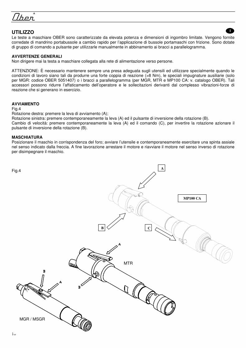
MP100 CA
A
CB
UTILIZZO I Le teste a maschiare OBER sono caratterizzate da elevata potenza e dimensioni di ingombro limitate. Vengono fornite corredate di mandrino portabussole a cambio rapido per l’applicazione di bussole portamaschi con frizione. Sono dotate di gruppo di comando a pulsante per utilizzarle manualmente in abbinamento ai bracci a parallelogramma. AVVERTENZE GENERALI Non dirigere mai la testa a maschiare collegata alla rete di alimentazione verso persone. ATTENZIONE: È necessario mantenere sempre una presa adeguata sugli utensili ed utilizzare specialmente quando le condizioni di lavoro siano tali da produrre una forte coppia di reazione (>8 Nm), le speciali impugnature ausiliarie (solo per MGR: codice OBER 5051407) o i bracci a parallelogramma (per MGR, MTR e MP100 CA: v. catalogo OBER). Tali accessori possono ridurre l’affaticamento dell’operatore e le sollecitazioni derivanti dal complesso vibrazioni-forze di reazione che si generano in esercizio. AVVIAMENTO Fig.4 Rotazione destra: premere la leva di avviamento (A); Rotazione sinistra: premere contemporaneamente la leva (A) ed il pulsante di inversione della rotazione (B). Cambio di velocità: premere contemporaneamente la leva (A) ed il comando (C), per invertire la rotazione azionare il pulsante di inversione della rotazione (B). MASCHIATURA Posizionare il maschio in corrispondenza del foro; avviare l’utensile e contemporaneamente esercitare una spinta assiale nel senso indicato dalla freccia. A fine lavorazione arrestare il motore e riavviare il motore nel senso inverso di rotazione per disimpegnare il maschio. Fig.4
MGR / MSGR
MTR

17
I CONNESSIONE PNEUMATICA CAMBIO VELOCITA’ (MP100 CA) Fig.4 La connessione pneumatica con l’attacco rapido diametro 4 mm., dovrà essere eseguita utilizzando per la comutazione una valvola monostabile a tre posizioni (tre vie). In assenza di aria nel raccordo rapido, il maschiatore avrà un regime di rotazione di circa 300 giri/minuto (rpm). Commutando la valvola a tre vie, (dando pressione al raccordo) il numero di giri varierà automaticamente a 100 giri/minuto (rpm). IMPORTANTE L’impiego della valvola è indispensabile per il corretto funzionamento del cambio di velocità, perché toglie la contropressione che impedirebbe il corretto avanzamento dell’attuatore.
GB PNEUMATIC EXCHANGE CONNECTION SPEED (MP100 CA) Fig.4 The pneumatic connection with the quick coupler diameter 4 mm., must be carried out using the switching a valve monostable three positions (three ways). In the absence of air in fast pipe fitting, the maschiatore will have a speed of about 300 revolutions per minute (rpm). Switching the three way valve, (giving pressure to the grande raccordo anulare) the number of laps will vary automatically to 100 revolutions per minute (rpm). IMPORTANT
Is the use of the valve is indispensable for the functioning of correct exchange of speed, because it removes the pressure that would prevent the smooth progress of the actuator.
F Vitesse de connexion change pneumatique (MP100 CA) Fig.4 La liaison pneumatique avec le coupleur rapide de diamètre 4 mm., doit être effectuée à l'aide du commutation d'une vanne monostable trois positions (trois façons). En l'absence d'air rapide en tuyauterie, le maschiatore auront une vitesse d'environ 300 tours par minute (rpm). Commutation de la vanne, trois cours (donnant la pression de la grande raccordo anulare) le nombre de tours variera automatiquement à 100 tours par minute (rpm). IMPORTANT Est l'utilisation de la vanne est indispensable pour le fonctionnement du correcte échange de vitesse, parce qu'elle supprime la pression que permettrait d'éviter le bon déroulement de l'actionneur.
D PNEUMATISCHE EXCHANGE CONNECTION SPEED (MP100 CA) Abb. 4 Die pneumatische Verbindung mit der schnellkupplung Durchmesser 4 mm., durchgeführt werden müssen mit dem umschalten ein Ventil monostabil drei Positionen (drei Möglichkeiten). In Abwesenheit von Luft in schnelle pipe fitting, die maschiatore wird eine Geschwindigkeit von etwa 300 Umdrehungen pro minute (rpm). Das Umschalten der drei Wege Ventil - (der Druck auf die Grande raccordo anulare) die Anzahl der Runden wird automatisch auf 100 Umdrehungen pro minute (rpm). Wichtig ist der Gebrauch des ventils ist unverzichtbar für das Funktionieren der richtig Austausch von geschwindigkeit, weil es entfernt den druck verhindern würde, dass den reibungslosen Ablauf des antriebes.
E Conexión Neumática cambio VELOCITA' (MP100 CA)

18
Fig.4 La conexión neumática con el ataque rápido diámetro 4 mm., deberá realizarse utilizando para la comutazione una válvula monostabile a tres posiciones (tres vías). En ausencia de aire en conexión rápida, el maschiatore tendrá un régimen de rotación de aproximadamente 300 revoluciones/minuto (rpm). ; La válvula de tres vías, (dando presión al enlace) el número de vueltas variará automáticamente a 100 revoluciones/minuto (rpm). IMPORTANTE uso de la válvula es indispensable para el correcto funcionamiento del cambio de velocidad, porque quita la contrapresión que impediría la correcta ejecución dell'attuatore.
Pnömatik trampa bağlantısı hızı (MP100 CA) Incir. 4 Pnömatik çabuk coupler çaplı bağlantı 4 milimitre., uygulanma kullanıyor değişiyor bir vana monostable. Çabuk boru fitting içindeki hava yokluğunun içinde, maschiatore bir dakika başına yaklaşık 300 devrim hızı var (rpm). Değişiyor üç yol vana, (baskı grande raccordo anulare veriyor) sayı kucak dakika başına 100 devrime otomatik olarak değişmeyecek (rpm). Önemli olur Vana yararı vazgeçilemez doğru çalışıyor trampa ol speed çünkü o pürüzsüz çalıştırıcı ilerlemesini önlemeyecek baskıyı kaldırır. USE GB OBER tapping heads are extremely powerful plus compact dimensions. They are supplied with quick release chucs for fitting tap holder bushes with clutch. They are supplied with a switch for manual use with parallelogram arms. GENERAL WARNINGS Never point the tap ping head towards people when it is connected to the power supply. WARNING: A firm grip must always be kept on the tools and, especially when the working conditions produce a high level of kickback (>8 Nm), always use the special auxiliary handles (only for MGR: OBER code 5051407) or the parallel arms (for MGR, MTR and MP100 CA: indicated in the OBER catalogue). These accessories can reduce the operator’s work load and the stress deriving from the complex vibrations and kickback generated during use. STARTING (Fig.4) Clockwise rotation: push the starting lever (A); Counterclockwise rotation: push the starting lever (A), and the button (B) at the same time. Change of speed: to contemporarily press the lever (A) and the command (C) to reverse the rotation to operate the button of inversion of the rotation (B). TAPPING Position the tap in its hole. Start up the tool and push in the direction indicated by the arrow. At the end of your work, stop the motor, and re-start the motor in the opposite sense of rotation to release the tap.
UTILISATION F Les têtes à tarauder OBER sont caractérisées par une puissance élevées et des dimensions d’encombrement limitées. Elles sont fournies équipées d’un mandrin porte-douilles à changement rapide pour l’application de douilles porte-douilles à changement rapide pour l’application de douilles porte-tarauds avec friction. Elles sont fournies avec groupe de commande à poussoir pour une utilisation manuelle en combinaison avec les bras à parallélogramme. PRECAUTIONS GENERALES Ne jamais diriger la tête à tarauder reliée au réseau d’alimentation vers les personnes. ATTENTION: Toujours maintenir une prise contrôlée des outils; utiliser les poignées auxiliaires (seulement pour MGR: code OBER 5051407), ou les bras a parallelogram (pour MGR, MTR et MP100 CA: indiqués dans le catalogue OBER),

19
spécialement si les conditions de travail sont telles qu’elles produisent un couple de réaction élevé (>8 Nm). Ces accessoires peuvent réduire la fatigue de l’opérateur et les sollicitations dérivant du complexe vibrations-forces de réaction qui sont générées au cours du fonctionnement. DEMARRAGE Fig.4 Rotation à droite: appuyer sur la manette (A). Rotation à gauche: appuyer sur la manettes (A) et le poussoir (B) dans le même temps. Échange de vitesse: presser le levier en même temps, (A), et le commandement (C), pour inverser la rotation actionner le bouton d'inversion de la rotation, (B). TARAUDAGE Positionner le taraud en face du trou. Mettre en marche l'outil et pousser en même temps, dans l'axe, dans le sens indiqué par la flèche. Quand l'usinage est terminé, arrêter le moteur et faire redémarrer le moteur dans le sens inverse de rotation pour libérer le taraud.
ANWENDUNG D Die Gewindebohrköpfe OBER sind sehr leistungsfähig und haben einen geringen Platzbedarf. Sie werden zusammen mit Spannfutter zur Buchsenhaltung mit Schnellwechsel geliefert, damit Gewindebohrerträgerbuchsen mit Kupplung verwendet werden können. Sie werden mit einem Steuersatz mit Drucktaste geliefert, damit man sie von Hand, zusammen mit den Prallelogrammarmen, verwenden kann. ALLGEMEINE HINWEISE Der angeschlossene Gewindebohrköpf darf nie auf Personen gerichtest werden. ACHTUNG:Bei den Geräten ist stets für festen Griff zu sorgen und besonders bei Arbeitsbedingungen, bei denen ein starkes Reaktionsmoment (>8 Nm) auftritt, die speziellen Hilfsgriffe (nur für MGR: OBER Bestellnr. 5051407) oder die Parallelarme (für MGR, MTR und MP100 CA: im Katalog von OBER angegeben) zu verwenden. Dieses Zubehör trägt dazu bei, die Ermüdung des Bedieners und die Belastungen duch die Kombination von Schwingungen und Reaktionskräften beim Betrieb einzuschränken. ANLAUF Abb.4 Rechtslauf: den Schalter (A) drücken; Linkslauf: Gleichzeitig Schalter (A) und den Linkslaufknopf (B) drücken. Getriebe: drücken Sie gleichzeitig die Hebel (A) und dem Befehl (C), die umkehrung der drehrichtung betätigen der Taste der Umkehrung der rotation (B). GEWINDEBOHREN Den Gewindebohrer in Übereinstimmung mit der Bohrung positionieren. Das Werkzeug einschalten und gleichzeitig in die vom Pfeil angegebene Richtung drücken. Nach Ausführung der Arbeit den Motor abstellen, das Werkzeug in umgekehrter Richtung anlassen, um den Gewindbohrer auszufahren.
USO E Los cabezales de roscado OBER son dotados de elevada potencia y reducida dimensión. Se suministran con mandrino portamachos de cambio rápido para la aplicación de mandrino portamachos con embrague. Se suministran con grupo de mando de pulsador para utilizarlos manulmente combinados con paralelogramos. ADVERTENCIAS GENERALES No hay que dirigir nunca el cabezal de roscado hacia las personas si está conectado a la red de alimentación. ATENCIÓN: Es necesario sujetar siempre en el modo adecuado las herramientas utilizando, especialmente cuando las condiciones de trabajo produzcan un par de reacción importante (>8 Nm), las empuñaduras auxiliares presentes a tal efecto (solo por MGR: código OBER 5051407), o los brazos de paralelogramo (por MGR, MTR y MP100 CA: indicados en el catálogo OBER). Dichos accesorios pueden reducir el esfuerzo del operador y las solicitaciones derivadas del conjunto vibraciones-fuerzas de reacción que se producen durante el funcionamiento. PUESTA EN MARCHA Fig.4 Rotación a la derecha: pulsar la palanca (A). Rotación a la izquierda: apretar la palanca (A) y el interruptor de inversíon de la marcha (B) al mismo tiempo. Cambio de velocidad: presionar al mismo tiempo la palanca (A) y el mando (C), para invertir la rotación accionar el botón de inversión de la rotación (B).

20
ROSCADO Colocar el macho en correspondencia con el agujero; Poner en marcha la herramienta y simultáneamente empujar en el sentido indicado por la flecha. Una vez terminada la elaboración detener el motor y poner nuevamente en marcha el motor en el sentido inverso para desocupar el macho.
KULLANIM OBER kılavuz başlıkları son derece sağlamdır ve küçük boyutlara sahiptir. Kavramalı kılavuz tutma kelepçesi montajı için hızlı çıkarılabilir torna kafaları ile birlikte teslim edilirler. Paralel kenar kollar ile manuel kullanım için bir anahtar ile birlikte teslim edilirler. GENEL UYARILAR Güç kaynağına bağlı iken kılavuz ping başlığını kesinlikle insanlara doğru tutmayın. UYARI: Özellikle yüksek seviyelerde geri tepmenin (>8 Nm) söz konusu olduğu çalışma koşullarında sağlam bir kavrama sağlanmalı ve mutlaka özel yardımcı saplar (yalnızca MGR: OBER kod 5051407) veya paralel kollar (MGR, MTR ve MP100 CA için: OBER kataloğunda gösterilmiştir) kullanılmalıdır. Bu aksesuarlar, kullanım sırasında oluşan karmaşık titreşim ve geri tepme etkilerinden kaynaklanan kullanıcı iş yükü ve gerilim seviyelerini azaltır. ÇALIŞTIRMA (Şekil 4) Saat yönünde döndürme: çalıştırma koluna basın (A); Saat yönünün tersine döndürme: çalıştırma koluna (A) ve düğmeye (B) aynı anda basın. Vites kutusu: kaldıraca simultane olarak bas ( A) ve komut ( C), reverse dönüş dönüşü ters çevirerek düğmesini çalıştırır (B). KILAVUZ ÇEKME Kılavuzu deliğine yerleştirin. Aleti çalıştırın ve ok ile gösterilen yöne itin. İşinizin sonunda motoru durdurun, ters döndürme yönünde yeniden çalıştırın ve kılavuzu çıkarın.
I MONTAGGIO DEGLI UTENSILI DI MASCHIATURA (fig.5) Le teste a maschiare OBER a richiesta vengono fornite complete di mandrino portabussole a cambio rapido; per il montaggio degli utensili si deve spingere a fondo il maschio (1) nella bussola (2); mentre per la loro sostituzione si deve premere la baionetta (P) ed estrarre. MONTAGGIO DELLA BUSSOLA PORTA-MASCHI (fig.5) Innestare bussola e maschio nel mandrino (3), facendo scorrere assialmente la manopola del mandrino, come indicato dalla freccia e rilasciare (viceversa per estrarre la bussola). Fig.5 SOSTITUZIONE MANDRINO (fig.6) Svitare il grano posto a lato del mandrino. Inserire tra corona e mandrino l’apposita chiave a bietta. Dare un colpo di mazzuolo sulla chiave per sfilare il mandrino dall’albero. Procedere al montaggio del mandrino assicurando l’accoppiamento mandrino-albero, pulendo accuratamente le superfici. Serrare il grano. Fig.6
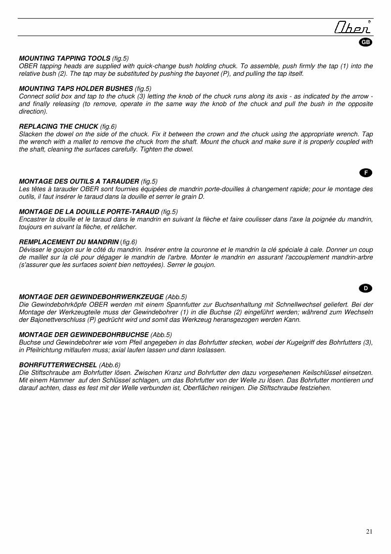
21
GB MOUNTING TAPPING TOOLS (fig.5) OBER tapping heads are supplied with quick-change bush holding chuck. To assemble, push firmly the tap (1) into the relative bush (2). The tap may be substituted by pushing the bayonet (P), and pulling the tap itself. MOUNTING TAPS HOLDER BUSHES (fig.5) Connect solid box and tap to the chuck (3) letting the knob of the chuck runs along its axis - as indicated by the arrow - and finally releasing (to remove, operate in the same way the knob of the chuck and pull the bush in the opposite direction). REPLACING THE CHUCK (fig.6) Slacken the dowel on the side of the chuck. Fix it between the crown and the chuck using the appropriate wrench. Tap the wrench with a mallet to remove the chuck from the shaft. Mount the chuck and make sure it is properly coupled with the shaft, cleaning the surfaces carefully. Tighten the dowel.
F MONTAGE DES OUTILS A TARAUDER (fig.5) Les têtes à tarauder OBER sont fournies équipées de mandrin porte-douilles à changement rapide; pour le montage des outils, il faut insérer le taraud dans la douille et serrer le grain D. MONTAGE DE LA DOUILLE PORTE-TARAUD (fig.5) Encastrer la douille et le taraud dans le mandrin en suivant la flèche et faire coulisser dans l'axe la poignée du mandrin, toujours en suivant la flèche, et relâcher. REMPLACEMENT DU MANDRIN (fig.6) Dévisser le goujon sur le côté du mandrin. Insérer entre la couronne et le mandrin la clé spéciale à cale. Donner un coup de maillet sur la clé pour dégager le mandrin de l'arbre. Monter le mandrin en assurant l'accouplement mandrin-arbre (s'assurer que les surfaces soient bien nettoyées). Serrer le goujon.
D MONTAGE DER GEWINDEBOHRWERKZEUGE (Abb.5) Die Gewindebohrköpfe OBER werden mit einem Spannfutter zur Buchsenhaltung mit Schnellwechsel geliefert. Bei der Montage der Werkzeugteile muss der Gewindebohrer (1) in die Buchse (2) eingeführt werden; während zum Wechseln der Bajonettverschluss (P) gedrücht wird und somit das Werkzeug heransgezogen werden Kann. MONTAGE DER GEWINDEBOHRBUCHSE (Abb.5) Buchse und Gewindebohrer wie vom Pfeil angegeben in das Bohrfutter stecken, wobei der Kugelgriff des Bohrfutters (3), in Pfeilrichtung mitlaufen muss; axial laufen lassen und dann loslassen. BOHRFUTTERWECHSEL (Abb.6) Die Stiftschraube am Bohrfutter lösen. Zwischen Kranz und Bohrfutter den dazu vorgesehenen Keilschlüssel einsetzen. Mit einem Hammer auf den Schlüssel schlagen, um das Bohrfutter von der Welle zu lösen. Das Bohrfutter montieren und darauf achten, dass es fest mit der Welle verbunden ist, Oberflächen reinigen. Die Stiftschraube festziehen.

22
E MONTAJE DE LAS HERRAMIENTAS DE ROSCADO (fig.5) Los cabezales de roscado OBER se suministran con el mandril portacasquillos con cambio rápido; para montar las herramientas hay que meter el macho en su casquillo correspondiente y apretar el pasador D. MONTAJE DEL CASQUILLO PORTAMACHOS (fig.5) Acoplar casquillo y terraja en el mandril tal como indica la flecha, haciendo deslizar axialmente la manopla del mandril, tal como indica la flecha, y soltarla. SUSTITUCION DEL MANDRIL (fig.6) Aflojar la tuerca a lado del mandril. Introducir, entre la corona y el mandril, la llave de cuña. Dar un golpe de mazo sobre la llave para extraer el mandril del eje. Montar el mandril asegurando el acoplamiento mandril-eje, limpiando las superficies con atención. Ajustar la tuerca.
KILAVUZ ALETLERİNİN MONTE EDİLMESİ (şekil 5) OBER kılavuz başlıkları hızlı değiştirme kelepçe tutma kavramaları ile birlikte teslim edilmektedir. Monte etmek için kılavuzu (1), ilgili kelepçeye (2) bastırın. Kılavuz, kavrama somununa (P) basılırken çekilerek de değiştirilebilir. KILAVUZ TUTMA KELEPÇELERININ MONTE EDILMESI (şekil 5) Kutu ve kılavuzu torna kafası başının eksen boyunca yer alacağı - okla gösterilen şekilde - ve daha sonra bırakılacağı şekilde torna kafasına (3) bağlayın (sökmek için torna kafası başını aynı şekilde çalıştırın ve kelepçeyi ters yönde çevirin. TORNA KAFASININ DEĞİŞTİRİLMESİ (şekil 6) Torna kafasının yan tarafındaki tespit pimini gevşetin. Uygun anahtarı kullanarak kafa ile torna kafası arasında sabitleyin. Anahtara çekiç ile vurarak torna kafasını çıkarın. Torna kafasını takın ve yüzeyleri dikkatlice temizleyerek mil ile uygun şekilde bağlandığından emin olun. Tespit pimini sıkın.
I DIFFICOLTÀ DI AVVIAMENTO. Qualora l'utensile collegato alla rete aria, non si avvii, verificare che la leva di alimentazione non sia bloccata, introdurre alcune gocce di nafta nel raccordo di alimentazione aria e tentare nuovamente l'avviamento. Se il motore non girasse ancora, staccare l'alimentazione e tentare di sbloccarlo nuovamente ruotando manualmente il mandrino. CALI DI POTENZA. Controllare che il foro d'ingresso aria non sia occluso e che l'aria sia adeguatamente lubrificata. Pulire il silenziatore allo scarico lavandolo con nafta. Si raccomanda di non rimuovere tale silenziatore: ciò porterebbe a prestazioni lievemente più elevate, ma contemporaneamente ad un aumento della rumorosità oltre i livelli previsti.
! ATTENZIONE: INTERROMPERE SEMPRE L'ALIMENTAZIONE DELL'ARIA COMPRESSA PRIMA DI ESEGUIRE SULL'UTENSILE OPERAZIONI DIVERSE DA QUELLA DI MASCHIATURA.
GB PROBLEMS IN STARTING. If the tool connected to the compressed air supply should not turn on, make sure the supply lever is not blocked, place a few drops of naphtha in the connection to the air supply and try once again to start the tool. If the motor is still not running, disconnect it from the pneumatic supply and try to release it by turning the chuck by hand. DECREASED POWER. Make sure the air inlet is not obstructed and that the air is properly lubricated. Clean the exhaust silencer with naphtha. Do not remove the silencer: this would result in a slightly higher performance, but at the same time it would increase noise beyond the foreseen levels.
! ATTENTION: ALWAYS INTERRUPT THE SUPPLY OF COMPRESSED AIR BEFORE USING THE TOOL FOR OTHER OPERATIONS RATHER THAN TAPPING.

23
F DIFFICULTES DE DEMARRAGE. Si l'outil branché sur le réseau d'air ne se met pas en marche, vérifiez que le bouton d'alimentation ne soit pas bloqué, versez quelques gouttes de d’huile dans l’orifice d'alimentation d'air et refaites-le partir Si le moteur ne tourne toujours pas, coupez l'alimentation et essayez encore de le débloquer en faisant tourner le mandrin à la main. BAISSES DE PUISSANCE. Contrôlez que le trou d'entrée d'air et le filtre métallique ne soient ni sales ni obstrués et lavez-les éventuellement avec du gazoil. Nettoyez le silencieux à hauteur de l'échappement d'air et éventuellement lavez-le avec du gas-oil. Nous recommandons de ne pas enlever ce silencieux: cela donnerait des performances légèrement plus élevées mais entraînerait simultanément une augmentation du bruit au-dessus des niveaux prevues.
! ATTENTION: COUPEZ TOUJOURS L'ALIMENTATION DE L'AIR COMPRIME AVANT TOUTE INTERVENTION QUELLE QU'ELLE SOIT SUR L'OUTIL A L'EXCEPTION DU TARAUDAGE
D ANLAUFSCHWIERIGKEITEN. Sollte das Werkzeug, obwohl es an das Druckluftnetz angeschlossen ist, nicht anlaufen, kontrollieren ob der Schalter blockiert ist, einige Tropfen Naphtha in das Anschlußstück der Luftzuführung geben und erneut anlaufen lassen. Falls der Motor immer noch nicht läuft, die Zuführung abtrennen und versuchen, ihn erneut zu lösen, indem das Bohrfutter manuell gedreht wird. LEISTUNGSABFALL. Kontrollieren, ob das Luftzufuhrloch und die Filrnetze nicht verstopft oder schmutzig sind und eventuell mit Naphtha reinigen. Den Schalldämpfer am Ausgang auf Verstopfung und Verschmutzung kontrollieren und eventuell mit Naphtha spülen. Diesen beim Arbeiten nicht entfernen; man würde zwar etwas bessere Leistungen erreichen, hätte aber zugleich eine Lärmerhöhung über die erlaubte Grenze hinaus. ! ACHTUNG: STETS DIE DRUCKLUFTZUFUHR UNTERBRECHEN, WENN AM WERKZEUG ARBEITEN
VORGENOMMEN WERDEN.
E DIFICULTAD DE PUESTA EN MARCHA. Cuando la herramienta conectada a la red del aire no se ponga en marcha, controlar que el interruptor de alimentación no esté bloqueado. Introducir unas gotas de gasóleo en el empalme de alimentación del aire e intentar ponerla en marcha nuevamente Si el motor no girase aun, desconectar la alimentación y tratar de desbloquearlo nuevamente haciendo girar el mandril en forma manual. PÉRDIDAS DE POTENCIA. Controlar que el orificio de entrada del aire y el filtro de red no estén obturados ni sucios; si es necesario, lavarlos con gasóleo. Limpiar el silenciador de descarga con gasóleo. Se aconseja no quitar dicho silenciador, ya que se obtendrian prestaciones mayores pero, al mismo tiempo, aumentaria el nivel acústico por encima de los limites previstos..
! ATENCIÓN: INTERRUMPIR SIEMPRE LA ALIMENTACIÓN DEL AIRE COMPRIMIDO ANTES DE EFECTUAR EN LA HERRAMIENTA CUALQUIER OPERACIÓN QUE NO SEA ENROSCAR/DESENROSCAR.
ÇALIŞTIRMA SORUNLARI. Basınçlı hava beslemesine bağlı aletin açılmaması durumunda besleme kolunun tıkanmış olmadığından emin olun, hava beslemesi bağlantısına birkaç damla neft damlatın ve bir kez daha çalıştırmayı deneyin. Motor yine de çalışmazsa, pnömatik besleme bağlantısını kesin ve torna kafasını elle çevirerek çıkarmaya çalışın. DÜŞÜK GÜÇ. Hava girişinin tıkanmış olmadığından ve havanın uygun şekilde yağlanmış olduğundan emin olun. Egzoz susturucuyu neft ile temizleyin. Susturucuyu çıkarmayın: bu performansı bir miktar artıracak, ancak öngörülen seviyelerin üzerinde gürültüye neden olacaktır.
! DİKKAT: ALETİ KILAVUZ AÇMA DIŞINDA HERHANGİ BİR İŞLEM İÇİN KULLANMADAN ÖNCE BASINÇLI HAVA BESLEMESİNİ MUTLAKA KESİN.

24
MANUTENZIONE I Eseguire periodicamente un lavaggio del motore introducendo nafta nella presa d'aria, far funzionare qualche secondo, poi lubrificare. Questa operazione basta spesso per rendere perfettamente efficiente l'utensile che ha perso potenza od addirittura si è bloccato a causa di intasamenti. Se l'utensile viene lasciato inattivo per lunghi periodi, è opportuno introdurre olio nella presa d'aria e farlo funzionare qualche secondo prima di riporlo. Le parti interne resteranno così lubrificate. Ogni 500 ore di lavoro circa, è consigliabile smontare l'utensile, verificare la condizione dei cuscinetti e del motore, pulire tutto e lubrificare di nuovo con grasso per estreme pressioni. Per questo tipo di intervento e per altri diversi da quelli sopraelencati è consigliabile rivolgersi ai Centri Assistenza autorizzati o direttamente a OBER.
! Le alette autolubrificanti (a richiesta) contengono PTFE. Osservare le normali precauzioni di salute e sicurezza concernenti il PTFE quando si maneggiano tali alette. Le particelle di usura delle alette che possono trovarsi nel motore e sulle alette stesse non devono venire a contatto col fuoco. Lavarsi le mani prima di fumare perché il PTFE riscaldato dalla brace può produrre esalazioni in grado di causare reazioni allergiche.
MAINTENANCE GB Periodically clean the motor by introducing naphtha through the air inlet, let the motor run for a few seconds and then lubricate. This operation is often sufficient to restore the tool to perfect efficiency after it has lost power or has even become jammed due to obstruction. If the tool is left unused for long periods we recommend putting some oil into the air inlet and letting it run for a few seconds before putting it away. In this way the internal components will remain lubricated. After approximately every 500 hours of operation, it is advisable to take the tool apart, check the condition of the bearings, clean the gears thoroughly and lubricate with grease for extreme pressures. For this type of maintenance or other operations not indicated above, we recommend contacting an authorized Assistance Center or directly contacting OBER.
! Self-lubricating vanes (on request) have a PTFE content. Observe the normal Health and Safety recommendations concerning PTFE when handling this type of vanes. The particles from wear of vanes that may be present inside the motor or on the vanes themselves must not get in contact with fire. Wash your hands before smokig as PTFE heated by the glow can produce fumes which may give rise to allergic reaction.
ENTRETIEN F Lavez régulièrement le moteur en versant du gas-oil dans la prise d'air, faites-le fonctionner quelques secondes, après quoi graissez-le. Il suffit bien souvent de cette seule opération pour obtenir un bon fonctionnement de l'outil qui a perdu de sa puissance ou encore qui s'est bloqué à cause d'une obstruction. Si l'outil reste inutilisé pendant de longues périodes, il convient de verser de l'huile dans la prise d'air et de le faire fonctionner pendant quelques secondes avant de le remettre à sa place. Ainsi l'intérieur restera lubrifié. Toutes les 500 heures environ de travail, il est opportun de démonter l'outil, vérifier l'état des roulements, nettoyer à fond les engrenages et les lubrifier à nouveau avec de la graisse par fortes pressions. Pour ce type d'intervention et pour d'autres qui ne seraient pas mentionnées ci-dessus, il est conseillé de s'adresser aux Centres d'Assistance agrées ou bien encore directement à OBER.
! Les ailettes autolubrifiantes contiennent du PTFE. Respectez les consignes habituelles de santé et de sécurité concernant le PTFE lorsque vouz manipulez ce type de ailettes. Les particules dues à l’usure des ailettes qui peuvent se trouver dans le moteur ou bien sur les ailettes ne doivent pas entrer en contact avec le feu. Lavez-vous les mains avant de fumer car le PTFE chauffé par la cendre peut produire des fumes pouvant développer des réactions allergiques.
WARTUNG D Regelmässig eine Motorreinigung vornehmen, indem Naphtha in den Belüftungsgrill gegeben wird, ein paar Minuten einschalten, dann schmieren. Meist reicht diese Operation, um ein Werkzeug, das an Leistung verloren oder sich wegen Verschmutzung sogar blockiert hat, wieder einwandfrei funktionstüchtig zu machen. Wird das Werkzeug für lange Zeit nicht verwendet, ist es ratsam, etwas Öl in den Belüftungsgrill zu geben, und es für ein paar Minuten einzuschalten, bevor man es wegräumt. Die Innenteile bleiben so geschmiert. Etwa alle 500 Arbeitsstunden ist es ratsam, das Werkzeug auseinanderzunehmen, die Lager zu prüfen, das Getriebe zu reinigen und erneut mit Hochdruck-Fett zu schmieren. Für diesen Eingriff, oder weitere, oben nicht genannte ist es ratsam, sich an die autorisierten Service-Stellen oder direkt an OBER zu wenden.
! Die selbstschmierenden (auf Anfrage) Lamellen im Gerät enthalten PTFE. Beim Umgang mit diesen Rotorblättern sind die allgemeinen Gesundheits- und Sicherheitsempfehlungen zu befolgen. Kleinste Teile dieser Lamellen können im Gehäuse oder an den Lamellen selbst vorkommen. Diese Partikel dürfen nicht mit Flammen in Kontakt kommen. Vor Rauchen die Hände waschen, weil erhitzte PTFE Teilchen Rauch entwickeln können der eine allergische Reaktion verursachen kann.
25
MANTENIMIENTO E Lavar periódicamente el motor introduciendo gasóleo en la toma del aire, dejarlo en marcha durante unos segundos y lubricarlo. A menudo, basta esta operación para restablecer perfectamente las prestaciones de una herramienta que haya perdido potencia o se haya bloqueado debido a obturaciones. Si no se utiliza la herramienta durante largos periodos, se aconseja introducir aceite dentro de la toma de aire y dejarla funcionar durante unos segundos antes de guardarla. De esta manera, las piezas interiores quedan lubricadas. Cada 500 horas de trabajo se aconseja desmontar la herramienta, controlar las condiciones de los cojinetes, limpiar completamente los engranajes y lubricar con grasa para presiones extremas. Para este tipo de intervención u otras diferentes a las citadas anteriormente, se aconseja ponerse en contacto con los Centros de Asistencia Autorizados o directamente con OBER.
! Las aletas autolubricantes (sobre pedido) contienen PTFE. Cuando se manipulen dichas aletas, hay que observar las precauciones normales de salud y seguridad relativas al PTFE. Las partículas de desgaste de las aletas que se pueden hallar en el motor o en las aletas mismas, no deberán entrar en contacto con el fuego. Antes de fumar es necesario lavarse las manos ya que las partículas de PTFE pueden producir reacciones alérgicas.
BAKIM Motoru düzenli olarak temizlemek için hava girişinden neft akıtıp birkaç saniye motoru çalıştırın ve ardından yağlayın. Alet gücünü kaybettikten veya bir engel nedeniyle tıkandıktan sonra aleti tekrar mükemmel şekilde verimli hale getirmek için bu işlem genellikle yeterlidir. Alet uzun süre çalıştırılmadıysa, aleti kaldırmadan önce hava giriş deliğine bir miktar yağ koyup, birkaç saniye çalıştırılmasını öneririz. Bu şekilde dahili bileşenler yağlanmış olacaktır. Yaklaşık her 500 saatlik çalışma süresinden sonra aletin yerinden çıkarılması, yatakların durumunun kontrol edilmesi, dişlilerin tamamen temizlenmesi ve aşırı basınçlar için gres yağı ile yağlanması tavsiye edilir. Bu tür bakım işlemleri ile yukarıda açıklanmayan diğer işlemler için bir yetkili Yardım Merkezine ya da doğrudan OBER'e başvurmanızı öneririz.
! Kendiliğinden yağlamalı pervanelerde (isteğe göre) PTFE içeriği bulunur. Bu tip pervaneler ile işlem yaparken PTFE hakkındaki Sağlık ve Güvenlik önerilerine uygun hareket edin. Motorun içinde veya pervanelerin üzerinde bulunan aşınma kaynaklı parçacıkların ateşle temas etmesi önlenmelidir. Alevle ısınan PTFE alerjik reaksiyonlara yol açan duman üretebileceğinden, sigara içmeden önce ellerinizi yıkayın.
26
MATERIALI I Gli utensili pneumatici Ober sono costituiti da parti di acciaio, alluminio, ghisa, gomma e plastica e non contengono sostanze nocive per l’ambiente e le persone. È comunque necessario prevedere uno smaltimento differenziato dei singoli materiali ed attenersi alle disposizioni nazionali in materia di riciclaggio e gestione dei rifiuti.
MATERIALS GB OBER pneumatic tools consist of parts in steel, aluminium, cast iron, rubber and plastic and do not contain substances which damage the environment or are harmful to people. However, the individual materials must be disposed of separately, following the National indications for recycling and handling waste.
MATERIAUX F Les outils pneumatiques Ober sont formés de pièces en acier, aluminium, fonte, caoutchouc et plastique et ne contiennent pas de substances nocives pour l’environnement et les personnes. Il est toutefois nécesessaire de prévoir une mise à la décharge différenciée des matériaux et de respecter les dispositions nationales en matière de recyclage et de traitement des déchets.
WERKSTOFFE D Die Pneumatikwerkzeuge von Ober bestehen auf Stahl, Aluminium, Gusseisen, Gummi und Kunststoff und enthalten keine gesundheits und umweltschädlichen Stoffe. Bei der Entsorgung ist jedoch die Trennung der einzelnen Werkstoffe vorzusehen und es müssen die im jeweiligen Land geltenden Vorschriften für Recycling und Abfallentsorgung beachtet werden.
MATERIALES E Las herramientas neumáticas Ober están realizadas con acero, aluminio, fundición y plástico; no contienen sustancias dañinas para el medio ambiente y las personas. En todo caso, es necesario eliminar los diferentes materials por separado y cumpliendo las disposiciones nacionales sobre reciclaje y gestión de los residuo.
MALZEMELER Ober pnömatik motorları, çevre ve insanlar için zararlı madde içermeyen çelik, alüminyum, dökme demir, kauçuk ve plastik bileşenlerden üretilmiştir. Ancak, her bir malzeme ulusal atık geri dönüşüm düzenlemelerine göre ayrı ayrı imha edilmelidir.

27
ACCESSORI / ACCESSORIES / ACCESSOIRES / ZUBEHÖR / ACCESORIOS / AKSESUARLAR MANDRINO A CAMBIO RAPIDO / QUICK RELEASE CHUCK / MANDRIN CHANGEMENT RAPIDE / SPANNFUTTER MIT SCHNELLWECHSEL / MANDRIL CON CAMBIO RÁPIDO / HIZLI DEĞIŞTIRILEBILIR TORNA KAFASI B12 cod. / code / code / Kode-Nr. / cód. / kod: 7620005.1 CH.GIRAMASCHI/TAP KEY/CLES PORTE TARAUDS/GEWINDEBOHRERHALTER/LLAVES GIRAMACHOS/ KILAVUZ ANAHTARI
CH.AVVITAPRIGIONIERI/STUD-BOLT TIGH.KEY/CLES FILETES/STIFTSCHRAUBEN-EINDREHER/LLAVES GIRA-PRIS / ÇİVİ-CIVATA SIKMA ANAHTARI
* 7/16 armadio / cabinet / armoire / Schrank / armario / kapalı MANDRINO PORTABUSSOLE ATTACCO RAPIDO / QUICK RELEASE BUSH HOLDING CHUCK / MANDRIN PORTE-DOUILLES À CHANGEMENT RAPIDE / SPANNFUTTER ZUR BUCHSENHALTUNG MIT SCHNELLWECHSEL / MANDRIL PORTACASQUILLOS CAMBIO RÁPIDO / HIZLI ÇIKARMA KELEPÇE TUTMA TORNA KAFASI mm 19 - B12→ cod. / code / code / Kode-Nr. / cód. / kod 3731001 (di corredo –standard – fourni – im Lieferumfang
– dotación estandard – standart MGR33-55-77 - MSGR33-55 - MTR115)
mm 31 - B12→ cod. / code / code / Kode-Nr. / cód. / kod 3731002 (di corredo – standard – fourni – im Lieferumfang – dotación estandard – standart MTR66-44)
mm 19 - B16→ cod. / code / code / Kode-Nr. / cód. / kod 3731003 mm 31 - B16→ cod. / code / code / Kode-Nr. / cód. / kod 3731004 (di corredo – standard – fourni – im Lieferumfang
– dotación estandard – standart MTR88-11-MP100 CA) BUSSOLE PORTA MASCHI A CAMBIO RAPIDO CON FRIZIONE / DOUILLES PORTE-MALES A CHANGEMENT RAPIDE AVEC EMBRAYAGE / QUICK RELEASE TAP HOLDER BUSHES WITH CLUTCH / BÜCHSEN ZUR ZAPFENHALTERUNG MIT SCHNELLSCHALTUNG UND KUPPLUNG / CASQUILLOS PORTA-MACHOS CAMBIO RÁPIDO CON EMBRAGUE
� 3.5 4 4.5 5 6 6.3 7 8 9 10
2.7 3 3.4 4 4.9 5 5.5 6.2 7 8 Attacco → 19 Fitting Fixation Wechsel Fijación
Bağlantı cod 3826403 3826404 3826405 3826406 3826407 3826408 3826409 3826410 3826411 3826412
� 7 8 9 10 11 12 12.5 14 16 18
5.5 6.2 7 8 9 9 10 11 12 14.5
Attacco → 31 Fitting Fixation
Wechsel Fijación
Bağlantı cod 3826418 3826419 3826420 3826421 3826422 3826423 3826424 3826425 3826426 3826427
cod. / code / code / Kode Nr. / cód. / kod
cod. / code / code / Kode Nr. / cód. / kod
cod. / code / code / Kode Nr. / cód. / kod

DICHIARAZIONE DI CONFORMITÀ DECLARATION OF CONFORMITY – CERTIFICAT DE CONFORMITE –
KONFORMITÄTSERKLÄRUNG – DECLARACION DE CONFORMIDAD – UYGUNLUK BEYANI
Noi – We – Nous – Wir – Nosotros
OBER S.p.A., Via Don Minzoni 19, 40057 Cadriano di Granarolo Emilia, Bologna - I
Dichiariamo sotto la nostra esclusiva responsabilità che il prodotto: Declare under our sole responsability that the product: Déclarons sous notre seule responsabilité que le produit: Erklärenhiermit, gemäss unserer alleinigen Verantwortung, dass das Gerät: Declaramos que, bajo nuestra responsabilidad exclusiva, el producto: Sorumluluk tamamen tarafımıza ait olmak üzere
Tipo – Type – Type – Typ – Tipo – Tip: MGR33-55-77 MSGR33-55 MTR11-44-66-88-115-MP100 CA
Matricola – Serial No. – N°. Serie – Serien-Nr. – No. de Serie – Seri No: da, from, de, von, de 1999 A0000 al quale la presente dichiarazione si riferisce, è conforme a quanto previsto dalla Direttiva 2006/42/CE. to which this declaration relates, is in compliance with the provisions of 2006/42/CE directive. object de ce certificat, est conforme aux prescriptions de la directive 2006/42/CE. auf das sich diese Erklärung bezieht, der Richtlinie 2006/42/CE entspricht. a lo que se refiere la presente declaración, cumple con todo lo establecido en la directiva 2006/42/CE. olan ürünün, 2006/42/CE yönergesinin hükümlerine tamamen uygun olduğunu beyan ederiz. Cadriano di Granarolo, li 29/12/2010
OBER S.p.A.
Via Don Minzoni, 19 - 40057 Cadriano di Granarolo E. (BO) - I Tel. 051 - 6020811 Fax 051 - 765035 Internet: www.ober.it e-mail: [email protected]