mase - university of belgrade
TRANSCRIPT

СЛЕДЕЊЕ, ПРОЦЕНА И САНАЦИЈА НА КОНСТРУКЦИИMONITORING, ASSESSMENT AND REHABILITATION OF STRUCTURES
MASEMACEDONIANASSOCIATION OFSTRUCTURALENGINEERS
INTERNATIONAL SYMPOSIUM
МЕЃУНАРОДЕН СИМПОЗИУМ
OHRID
18
2 - 5 2019октомвриnd thOctober, 2 - 5 , 2019
ОХРИД
ЗБОРНИК НА ТРУДОВИPROCEEDINGS
MASE ДГКМ Macedonian Association of Structural Engineers
Друштво на градежните конструктори на Македонија
Proceedings
Зборник на трудови
Ohrid, North Macedonia, 2 – 5 October 2019 Охрид, Северна Македонија, 2 – 5 Октомври 2019
th International Symposium ти Меѓународен с и м п о з и у м

PROCEEDINGS OF THE 18th INTERNATIONAL SYMPOSIUM OF MASE
ЗБОРНИК НА ТРУДОВИ 18ТИ МЕЃУНАРОДЕН СИМПОЗИУМ НА ДГКМ
Publisher: MASE - Macedonian Association of Structural Engineers Faculty of Civil Engineering, Blvd. Partizanski odredi No. 24 P.Box. 560, 1000 Skopje, Republic of North Macedonia e-mail: [email protected]; website: www.mase.gf.ukim.edu.mk
Издавач: ДГКМ - Друштво на Градежни Конструктори на Македонија Градежен Факултет, бул. Партизански одреди бр. 24 П.Ф. 560, 1000 Скопје, Република Северна Македонија e-mail: [email protected]; website: www.mase.gf.ukim.edu.mk
Editor: Meri Cvetkovska, President of MASE
За издавачот: Мери Цветковска, Претседател на ДГКМ
Executive Committee of MASE and Organizing Committee of the 18th International Symposium of MASE: Meri Cvetkovska, Andrea Serafimovski, Ana Trombeva Gavriloska, Darko Nakov, Koce Todorov, Roberta Apostolska, Daniel Cekov, Sonja Cherepnalkovska, Iva Dzagora, Ilija Markov, Vladimir Vitanov, Denis Popovski, Ivana Dimitrova, Goran Jekic, Nikola Postolov, Riste Volchev
Претседателство на ДГКМ и Организационен одбор на 18тиот Меѓународен симпозиум на ДГКМ: Мери Цветковска, Андреа Серафимовски, Ана Тромбева Гаврилоска, Дарко Наков, Коце Тодоров, Роберта Апостолска, Даниел Цеков, Соња Черепналковска, Ива Џагора, Илија Марков, Владимир Витанов, Денис Поповски, Ивана Димитрова, Горан Јекиќ, Никола Постолов, Ристе Волчев
Technical staff of the Symposium: Simona Bogoevska, Cvetanka Chifliganec, Vladimir Damjanovski, Marija Docevska, Milica Jovanoska, Kristina Milkova, Mile Partikov, Elena Cvetkovska, Evgenija Stojkoska, Aleksandra Cubrinovska, Sofija Koceva, Dejan Janev, Dejan Gegovski, Stefan Micevski, Jordanka Chaneva
Техничка служба на Симпозиумот: Симона Богоевска, Цветанка Чифлиганец, Владимир Дамјановски, Марија Доцевска, Милица Јованоска, Кристина Милкова, Миле Партиков, Елена Цветковска, Евгенија Стојкоска, Александра Чубриновска, Софија Коцева, Дејан Јанев, Дејан Геговски, Стефан Мицевска, Јорданка Чанева
Grafical design of cover page and Symposium poster: Mitko Hadzi Pulja, Betim Zeqiri Faculty of Architecture, UKIM, Skopje
Графички дизајн на корицата и плакатот на Симпозиумот: Митко Хаџи Пуља, Бетим Зекири Архитектонски факултет, УКИМ, Скопје
e-book: електронско издание: ISBN 978-608-4510-36-9

DESIGN OF 120M GUYED STEEL MAST IN ALIBUNAR ACCORDING TO EUROCODE
Miroslav MARJANOVIĆ 1, Mira PETRONIJEVIĆ 2
ABSTRACT
Guyed masts are slender tall structures widely used to support different kinds of antennas in telecommunications. They consist of a vertical tall mast laterally supported at several levels along its height by sets of inclined pre-tensioned guys. The analysis and design of guyed masts is complex and requires special knowledge and experience because of: (1) non-linear behavior of guys, (2) the wind and ice loads, which accurate estimation is often difficult, and (3) the dynamic fluctuations of the wind load, to which the guyed mast is extremely sensitive. A dynamic stochastic analysis of guyed masts is complex and time consuming, so methods based on equivalent static analysis are usually used.
One relatively reliable simplified procedure, based on static patch wind loads, has been developed and adopted in Eurocode 3: Part 3-1: Towers, masts and chimneys. This procedure was applied to calculate member forces in 125m high anemometer guyed mast in the Alibunar municipality. The considered mast is spatial lattice structure with triangular cross sections and diagonal infill, composed of circular elements. The triangular cross sections and the pipe circular elements of mast structure were chosen in preliminary design to reduce the exposure of the structure to the wind load. The spatial stability of the mast is provided by 48 guys, attached to the mast at 11 different levels and anchored in 12 RC anchor blocks radially arranged around the central mast. Geometrically nonlinear analysis was performed using SAP2000 and obtained results are presented.
The ULS and stability check of 125m high anemometer guyed mast was performed using the procedure based on static patch wind loads adopted in Eurocode 3: Part 3-1. Geometrically nonlinear analysis was carried out using SAP2000. Loadings were calculated for the fundamental wind velocity vb,0 = 32 m/s, terrain type II, the ice thickness of 10mm and ice density ice = 900kg/m3.
The maximum forces in the mast legs were obtained for loading case 2: G + P + 1.2W. The variation of internal forces occurs at the heights where the cables are connected. In these zones, the forces in the leg elements vary slightly, indicating the correct choice of cable positions. The most stressed elements satisfied ultimate limit state (ULS) and stability checks.
Keywords: Guyed mast; Wind loading; Patch wind loads; Eurocode
1 Assistant Professor, Faculty of Civil Engineering, University of Belgrade, Serbia, [email protected] 2 Professor, Faculty of Civil Engineering, University of Belgrade, Serbia, [email protected]
Северна Македонија П.Фах 560, 1001 Скопје Партизански одреди 24,
ДГКМ MASE ДРУШТВО НА ГРАДЕЖНИТЕ КОНСТРУКТОРИ НА МАКЕДОНИЈА
MACEDONIAN ASSOCIATION OF STRUCTURAL ENGINEERS
Partizanski odredi 24, P. Box 560, 1001 Skopje North Macedonia
[email protected] http://mase.gf.ukim.edu.mk
SS - 9
1090

1. INTRODUCTION
Guyed masts are slender tall structures widely used to support different kinds of antennas in telecommunications. They consist of a vertical tall mast laterally supported at several levels along its height by sets of inclined pre-tensioned guys. The major loads for a guyed mast are wind and ice. The structural analysis of a guyed mast is complex, due to non-linear behavior of structural system and the random nature of the wind loads. A procedure proposed in Eurocode 3: Part 3-1: Towers, masts and chimneys [6] for calculating the fluctuating wind component is based on the static patch wind loads. In this study a control static calculation of an anemometer guyed mast 125m high was carried out using EC [6]. The conclusion of structural analysis and stress control is that structure was well designed and the guys position was properly arranged.
Fig. 1. (a) location, (b) autonomous power supply, (c-d) installed mast
2. DESCRIPTION OF THE STRUCTURE
The observed guyed mast is designed for meteorological testing of wind parameters at different altitudes in the territory of Alibunar municipality (Fig. 1a). It has an autonomous power supply (Fig. 1b), and measuring equipment that records changes in wind speed and direction, air pressure, relative humidity, solar radiation intensity, rain and snow amounts, and temperature. The guyed mast structure consists of a vertical mast-column and 48 guys distributed in eleven levels. The installed structure is shown in Fig. 1c and Fig. 1d.
The mast structure, shown in Fig. 2a and Fig. 2b, consists of: - the first segment, forming a hinge connection with the foundation, 0.91m long, - the middle part, consisting of 41 standard segments (S1-S41), 3.00m long, - the last segment, carrying measuring device and lightning rod, 1.93m long.
The standard segment is a spatial lattice structure of triangular cross-section and side length of 0.75m. It is composed of: leg members, Ø60x5mm, horizontal and diagonal elements welded to the leg members, Ø33x3mm and Ø27x3mm, according to Fig. 2d. The connection between the segments is made through the bearing plates and prestressed bolts M16, strength class 8.8. The mast is hinged to the central foundation by screws M42, strength class 8.8. The guys are Ø8mm or Ø10mm thick, depending on their position. 8mm thick guys are made of galvanized steel with a tensile strength of 1770 N / mm2, class 6x19 + FC, with a minimum breaking force of 35.7kN. 10mm thick guys are made of galvanized steel with a tensile strength of 1770 N / mm2, 6x37 + FC, Fmin = 57.6kN.
The mast is supported by a central RC foundation. The guys are anchored to 12 RC anchoring blocks radially spaced around the central foundation.
3. ACTIONS ON THE STRUCTURE
All actions have been calculated in accordance with Eurocode [1-8] and the relevant ISO standard [9]. The design values of the actions are determined according to the load combinations defined in [1, 6]. The following loads have been considered: self-weight and additional dead load, ice load, wind and seismic actions.
1091

Fig. 2. (a) Vertical cross section of the mast, (b) mast layout, (c) layout of the standard segment with
considered wind directions and (d) standard segment
1092
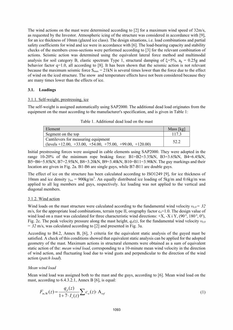
The wind actions on the mast were determined according to [2] for a maximum wind speed of 32m/s, as requested by the Investor. Atmospheric icing of the structure was considered in accordance with [9], for an ice thickness of 10mm (glazed ice class). The design situations, i.e. load combinations and partial safety coefficients for wind and ice were in accordance with [6]. The load-bearing capacity and stability checks of the members cross-sections were performed according to [3] for the relevant combination of actions. Seismic action was determined using the equivalent lateral force method and multimodal analysis for soil category B, elastic spectrum Type 1, structural damping of =5%, ag = 0.25g and behavior factor q=1.0, all according to [8]. It has been shown that the seismic action is not relevant because the maximum seismic force Smax = 21kN is several times lower than the force due to the effect of wind on the iced structure. The snow and temperature effects have not been considered because they are many times lower than the effects of ice.
3.1. Loadings
3.1.1. Self-weight, prestressing, ice
The self-weight is assigned automatically using SAP2000. The additional dead load originates from the equipment on the mast according to the manufacturer's specification, and is given in Table 1:
Table 1. Additional dead load on the mast
Element Mass [kg] Segment on the top 117.3 Cantilevers for measuring equipment (levels +12.00, +33.00, +54.00, +75.00, +99.00, +120.00)
52.2
Initial prestressing forces were assigned in cable elements using SAP2000. They were adopted in the range 10-20% of the minimum rope braking force: B1=B2=3.35kN, B3=3.65kN, B4=6.45kN, B5=B6=5.85kN, B7=2.95kN, B8=3.20kN, B9=3.40kN, B10=B11=3.90kN. The guy markings and their location are given in Fig. 2a. B1-B6 are single guys, while B7-B11 are double guys.
The effect of ice on the structure has been calculated according to ISO1249 [9], for ice thickness of 10mm and ice density ice = 900kg/m3. An equally distributed ice loading of 5kg/m and 0.6kg/m was applied to all leg members and guys, respectively. Ice loading was not applied to the vertical and diagonal members.
3.1.2. Wind action
Wind loads on the mast structure were calculated according to the fundamental wind velocity vb,0 = 32 m/s, for the appropriate load combinations, terrain type II, orography factor co=1.0. The design value of wind load on a mast was calculated for three characteristic wind directions: +X, -X i Y, (90 o, 180 o, 0o), Fig. 2c. The peak velocity pressure along the mast height, qp(z), for the fundamental wind velocity vb,0
= 32 m/s, was calculated according to [2] and presented in Fig. 3a.
According to B4.2, Annex B, [6], 3 criteria for the equivalent static analysis of the guyed mast be satisfied. A check of this conditions showed that equivalent static analysis can be applied for the adopted geometry of the mast. Maximum actions in structural elements were obtained as a sum of equivalent static action of the: mean wind load, corresponding to a 10-minute mean wind velocity in the direction of wind action, and fluctuating load due to wind gusts and perpendicular to the direction of the wind action (patch load).
Mean wind load
Mean wind load was assigned both to the mast and the guys, according to [6]. Mean wind load on the mast, according to 6.4.3.2.1, Annex B [6], is equal:
,W
( )( ) ( ) A
1 7 ( )p
m w refv
q zF z c z
I z
(1)
1093
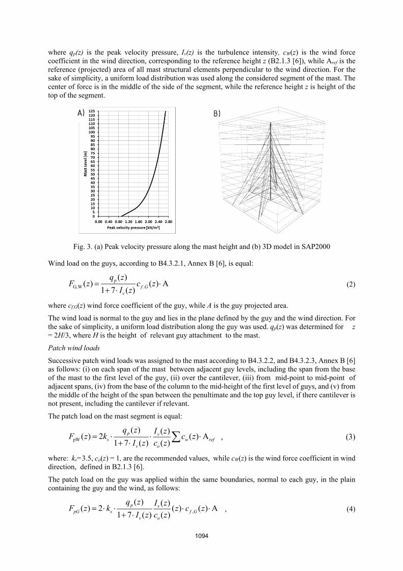
where qp(z) is the peak velocity pressure, Iv(z) is the turbulence intensity, cW(z) is the wind force coefficient in the wind direction, corresponding to the reference height z (B2.1.3 [6]), while Aref is the reference (projected) area of all mast structural elements perpendicular to the wind direction. For the sake of simplicity, a uniform load distribution was used along the considered segment of the mast. The center of force is in the middle of the side of the segment, while the reference height z is height of the top of the segment.
Fig. 3. (a) Peak velocity pressure along the mast height and (b) 3D model in SAP2000
Wind load on the guys, according to B4.3.2.1, Annex B [6], is equal:
G,W .
( )( ) ( ) A
1 7 ( )p
f Gv
q zF z c z
I z
(2)
where cf,G(z) wind force coefficient of the guy, while A is the guy projected area.
The wind load is normal to the guy and lies in the plane defined by the guy and the wind direction. For the sake of simplicity, a uniform load distribution along the guy was used. qp(z) was determined for z = 2H/3, where H is the height of relevant guy attachment to the mast.
Patch wind loads
Successive patch wind loads was assigned to the mast according to B4.3.2.2, and B4.3.2.3, Annex B [6] as follows: (i) on each span of the mast between adjacent guy levels, including the span from the base of the mast to the first level of the guy, (ii) over the cantilever, (iii) from mid-point to mid-point of adjacent spans, (iv) from the base of the column to the mid-height of the first level of guys, and (v) from the middle of the height of the span between the penultimate and the top guy level, if there cantilever is not present, including the cantilever if relevant.
The patch load on the mast segment is equal:
pW
( ) ( )( ) 2 ( ) A
1 7 ( ) ( )p v
s w refv o
q z I zF z k c z
I z c z
, (3)
where: ks=3.5, co(z) = 1, are the recommended values, while cW(z) is the wind force coefficient in wind direction, defined in B2.1.3 [6].
The patch load on the guy was applied within the same boundaries, normal to each guy, in the plain containing the guy and the wind, as follows:
,
( ) ( )( ) 2 ( ) ( ) A
1 7 ( ) ( )p v
pG s f Gv o
q z I zF z k z c z
I z c z
, (4)
1094

where ks = 3.5, while cf,G(z) is the guy wind force coefficient given in B2.1.3, Annex B [6]. For simplification the patch loading was 'smeared' over the whole height of the relevant guys by multiplying the above wind load by the ratio zp/zG, where zp is the "height" of the patch on the actual guy and zG is the height to the attachment of the guy to the mast.
Forces due to the patch loads Sp,Li are obtained using nonlinear static analysis, as the difference of: (i) forces due to the sum of the mean and patch wind load, and (ii) the forces due to the mean wind load. The total effect of wind fluctuation (patch load), Sp, is obtained by combining individual effects as:
2
1pLi
N
Pi
S S
(5)
where N is the total number of patch load cases. The overall effect on the structure, which introduces the effect of wind fluctuation, is equal to:
ST = SM SP, (6)
where SM is the effect of mean wind load, while SP is the effect of patch load.
3.1.3. The effect of atmospheric icing combined with the effect of wind
The icing of the mast significantly increases the weight of the structure, while the thickness of the ice increases the surface of the structural elements exposed to the wind. Therefore the wind force on the structure increases, which may have a very adverse effect on the mast. The calculation of the wind effect is the same as for the ice-free structure, with the changes in the thickness of the structural elements and appropriate drag coefficients.
The effects of ice and wind are combined in two ways: - Dominant wind (high probability of occurrence) + associated ice (low probability), - Dominant ice (high probability of occurrence) + associated wind (low probability).
Exposed areas of one characteristic segment of structure A, solidity ratios , and wind force coefficients cW and cG, for the three characteristic wind directions with respect to the X axis, 0o, 90o, and 180o, are given in Table 2. For the iced structure, exposed surfaces are significantly larger. Due to the low probability that a 50-year wind and high ice will occur simultaneously, a coefficient k = 0.40, which reduces the wind pressure on the iced structure, was introduced [9].
Table 2. Exposed areas, solidity ratios and wind force coefficients for the mast characteristic segment and guy ropes
NO ICE ICE = 10mm 0o 90o 180o 0o 90o 180o
A [m2] 0.58 0.56 0.83 0.85 0.82 1.23 [-] 0.24 0.29 0.35 0.36 0.42 0.51 cW [-] 1.42 1.40 1.35 1.34 1.31 1.30 cG [-] 1.20 1.25
4. STATIC ANALYSIS
Equivalent static nonlinear analysis was performed using SAP2000 14.2. The mast is modeled as a spatial lattice structure supported by 48 guys at 11 levels, Fig. 3b. The initial prestressing forces have been assigned to the cable elements. According to EN1993-1-11, the catenary effect was taken into account by applying an effective modulus of elasticity for guys, Et = 130 GPa (combinations without ice load) and Et = 121 GPa (combinations with ice loads).
Geometrically nonlinear analysis was performed with P- effects. Therefore, all load combinations are constructed as the independent load cases, without the superposition principle.
1095

4.1. Wind pressure according to EN1991-4 and EN1993-3-1
Mean wind load
The mean wind load for the iced and ice-free situation is assigned as a distributed load in the horizontal direction on the leg members. In Table 3 point resultant forces Fm,W, acting on each mast segment, as well as, distributed wind load across the guys FGW, are presented.
Table 3. Mean wind load
z qp(z)
NO ICE ICE = 10mm 0o 90o 180o
FGw(z) 0o 90o 180o
FGw(z) Fm,w(z) Fm,w(z) Fm,w(z) Fm,w(z) Fm,w(z) Fm,w(z)
m kN/m2 kN kN kN kN/m2 kN kN kN kN/m2 0.0 0.91 0.26 0.25 0.35 0.38 0.36 0.34 0.50 0.39
12.0 1.58 0.58 0.54 0.78 0.83 0.80 0.74 1.11 0.87 21.0 1.82 0.71 0.66 0.95 1.01 0.97 0.90 1.35 1.05 33.0 2.02 0.82 0.76 1.09 1.17 1.12 1.05 1.55 1.22 42.0 2.14 0.88 0.82 1.18 1.26 1.20 1.12 1.67 1.31 54.0 2.26 0.95 0.88 1.27 1.35 1.29 1.21 1.80 1.41 63.0 2.33 0.99 0.92 1.32 1.41 1.35 1.30 1.88 1.47 75.0 2.42 1.04 0.97 1.39 1.48 1.42 1.33 1.97 1.54 87.0 2.49 1.08 1.01 1.44 1.54 1.47 1.38 2.05 1.61 99.0 2.56 1.12 1.04 1.50 1.60 1.53 1.43 2.13 1.66 108.0 2.60 1.15 1.07 1.53 1.63 1.56 1.46 2.17 1.70 120.0 2.66 1.18 1.10 1.57 1.68 1.60 1.50 2.23 1.75 125.0 2.68 1.19 1.11 1.59 1.70 1.62 1.52 2.26 1.77
Patch wind load
Patch wind load comprises 23 load cases that are assigned from segment to segment, with a + or - sign, resulting in a total of 46 cases. The first 12 cases are shown in Fig. 4.
Fig. 4. Load cases due to wind action on the structure
Considering the above wind loads, it is concluded that the wind direction at an angle of 180o (-X), Fig. 2c, is relevant, since in this case the maximum wind pressure on the structural elements were generated. In accordance to EN1993-3-1, this direction was used to check the design of all structural elements, so, only the effects of wind in this direction is presented.
1096
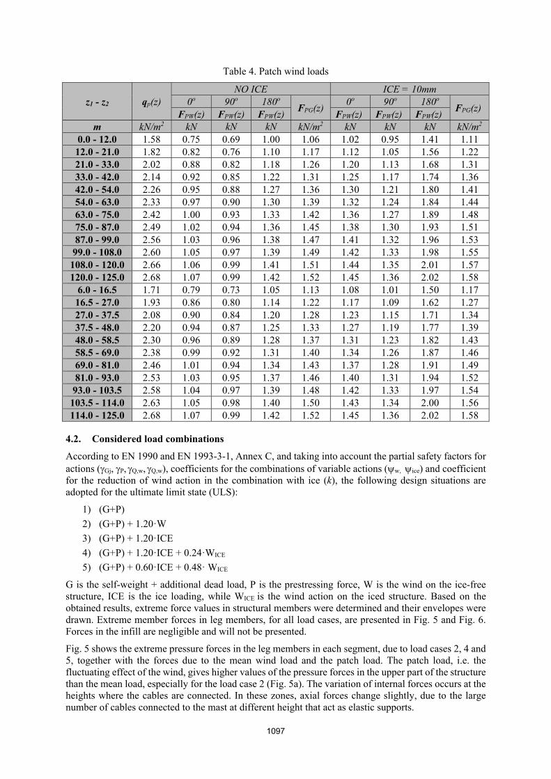
Table 4. Patch wind loads
z1 - z2 qp(z) NO ICE ICE = 10mm
0o 90o 180o FPG(z)
0o 90o 180o FPG(z)
FPW(z) FPW(z) FPW(z) FPW(z) FPW(z) FPW(z) m kN/m2 kN kN kN kN/m2 kN kN kN kN/m2
0.0 - 12.0 1.58 0.75 0.69 1.00 1.06 1.02 0.95 1.41 1.11 12.0 - 21.0 1.82 0.82 0.76 1.10 1.17 1.12 1.05 1.56 1.22 21.0 - 33.0 2.02 0.88 0.82 1.18 1.26 1.20 1.13 1.68 1.31 33.0 - 42.0 2.14 0.92 0.85 1.22 1.31 1.25 1.17 1.74 1.36 42.0 - 54.0 2.26 0.95 0.88 1.27 1.36 1.30 1.21 1.80 1.41 54.0 - 63.0 2.33 0.97 0.90 1.30 1.39 1.32 1.24 1.84 1.44 63.0 - 75.0 2.42 1.00 0.93 1.33 1.42 1.36 1.27 1.89 1.48 75.0 - 87.0 2.49 1.02 0.94 1.36 1.45 1.38 1.30 1.93 1.51 87.0 - 99.0 2.56 1.03 0.96 1.38 1.47 1.41 1.32 1.96 1.53
99.0 - 108.0 2.60 1.05 0.97 1.39 1.49 1.42 1.33 1.98 1.55 108.0 - 120.0 2.66 1.06 0.99 1.41 1.51 1.44 1.35 2.01 1.57 120.0 - 125.0 2.68 1.07 0.99 1.42 1.52 1.45 1.36 2.02 1.58
6.0 - 16.5 1.71 0.79 0.73 1.05 1.13 1.08 1.01 1.50 1.17 16.5 - 27.0 1.93 0.86 0.80 1.14 1.22 1.17 1.09 1.62 1.27 27.0 - 37.5 2.08 0.90 0.84 1.20 1.28 1.23 1.15 1.71 1.34 37.5 - 48.0 2.20 0.94 0.87 1.25 1.33 1.27 1.19 1.77 1.39 48.0 - 58.5 2.30 0.96 0.89 1.28 1.37 1.31 1.23 1.82 1.43 58.5 - 69.0 2.38 0.99 0.92 1.31 1.40 1.34 1.26 1.87 1.46 69.0 - 81.0 2.46 1.01 0.94 1.34 1.43 1.37 1.28 1.91 1.49 81.0 - 93.0 2.53 1.03 0.95 1.37 1.46 1.40 1.31 1.94 1.52
93.0 - 103.5 2.58 1.04 0.97 1.39 1.48 1.42 1.33 1.97 1.54 103.5 - 114.0 2.63 1.05 0.98 1.40 1.50 1.43 1.34 2.00 1.56 114.0 - 125.0 2.68 1.07 0.99 1.42 1.52 1.45 1.36 2.02 1.58
4.2. Considered load combinations
According to EN 1990 and EN 1993-3-1, Annex C, and taking into account the partial safety factors for actions (Gj, P, Q,w, Q,w), coefficients for the combinations of variable actions (w, ice) and coefficient for the reduction of wind action in the combination with ice (k), the following design situations are adopted for the ultimate limit state (ULS):
1) (G+P)
2) (G+P) + 1.20ꞏW
3) (G+P) + 1.20ꞏICE
4) (G+P) + 1.20ꞏICE + 0.24ꞏWICE
5) (G+P) + 0.60ꞏICE + 0.48ꞏ WICE
G is the self-weight + additional dead load, P is the prestressing force, W is the wind on the ice-free structure, ICE is the ice loading, while WICE is the wind action on the iced structure. Based on the obtained results, extreme force values in structural members were determined and their envelopes were drawn. Extreme member forces in leg members, for all load cases, are presented in Fig. 5 and Fig. 6. Forces in the infill are negligible and will not be presented.
Fig. 5 shows the extreme pressure forces in the leg members in each segment, due to load cases 2, 4 and 5, together with the forces due to the mean wind load and the patch load. The patch load, i.e. the fluctuating effect of the wind, gives higher values of the pressure forces in the upper part of the structure than the mean load, especially for the load case 2 (Fig. 5a). The variation of internal forces occurs at the heights where the cables are connected. In these zones, axial forces change slightly, due to the large number of cables connected to the mast at different height that act as elastic supports.
1097

Fig. 5. Extreme values of pressure forces in the leg members Nc,Ed (PATCH, MEAN, TOTAL):
(a) Load combination 2, (b) Load combination 4 (c) Load combination 5
Fig. 6. (a) Extreme values of pressure forces in the leg members for load combinations 1 and 3 (b)
Envelope of pressure forces, (c) Envelope of tension forces
1098

Fig. 6a illustrates the maximum axial forces in the leg member in each level due to the load combinations 1 and 3. The icing causes an increase in the compressive force of the elements. The maximum increase in normal force occurs in the elements of the first segment and equals 43%. Envelopes of pressure and tension member forces, taking into account all load combinations 1-5, are presented in Fig. 6b and Fig. 6c. Extreme values of axial forces in the mast legs occure at load combination 2, and are equal Nc,Ed,min
= -179.05 kN and Nt,Ed,max = 40.38 kN.
Based on the obtained member forces, the ultimate limit state (ULS) and stability checks of all structural members were performed according to [3], while the joints calculation was performed according to [4]. Both controls showed that dimensions of all elements are satisfactory. The serviceability limit state (SLS) was not considered in this paper.
5. CONCLUSIONS
The ULS and stability check of 125m high anemometer guyed mast was performed using procedure based on static patch wind loads adopted in Eurocode 3: Part 3-1. Geometrically nonlinear analysis was carried out using SAP2000. Loading were calculated for the fundamental wind velocity vb,0 = 32 m/s, terrain type II, the ice thickness 10mm and ice density ice = 900kg/m3. The maximum influences in the mast legs were obtained for loading case 2: G + P + 1.2W. The variation of internal forces occurs at the heights where the cables are connected (Fig. 5). In these zones, the forces in the leg elements vary slightly, indicating the correct choice of cable position. The most stressed elements satisfied ultimate limit state (ULS) and stability.
ACKNOWLEDGEMENTS
This research is carried out within the Projects TR36046 and TR36048 supported by the Ministry of Education, Science and Technological Development, Republic of Serbia.
REFERENCES
[1] European Committee for Standardization - CEN (2002). Eurocode 0: Basis of Structural Design. Brussels, Belgium.
[2] European Committee for Standardization - CEN (2005). Eurocode 1: Actions on structures - Part 1-4: General actions - Wind actions. Brussels, Belgium.
[3] European Committee for Standardization - CEN (2005). Eurocode 3: Design of steel structures - Part 1-1: General rules and rules for buildings. Brussels, Belgium.
[4] European Committee for Standardization - CEN (2005). Eurocode 3: Design of steel structures - Part 1-8: Design of joints. Brussels, Belgium.
[5] European Committee for Standardization - CEN (2006). Eurocode 3: Design of steel structures - Part 1-11: Design of structures with tension components. Brussels, Belgium.
[6] European Committee for Standardization - CEN (2006). Eurocode 3: Design of steel structures - Part 3-1: Towers, masts and chimneys – Towers and masts. Brussels, Belgium.
[7] European Committee for Standardization - CEN (2004). Eurocode 7: Geotechnical design - Part 1: General rules. Brussels, Belgium.
[8] European Committee for Standardization - CEN (2004). Eurocode 8: Design of structures for earthquake resistance – Part 1: General rules, seismic actions and rules for buildings. Brussels, Belgium.
[9] ISO 12494:2017. Atmospheric icing of structures. International Organization for Standardization, 2017.
1099