masonry infilling effect on seismicprofdoc.um.ac.ir/articles/a/1012294.pdf · masonry infilling...
TRANSCRIPT


Masonry Infilling Effect On Seismic Vulnerability and Performance Level of High
Ductility RC Frames
M Ghalehnovi a , H Shahraki b
a University of Sistan and Baluchestan , Zahedan , Iran, Email : ghalehnovi @ yahoo .com. b University of Sistan and Baluchestan , Zahedan , Iran, Shahraki_h74@ yahoo .com
Abstract. In last years researchers preferred behavior-based design of structure to force-based one for designing and construction of the earthquake- resistance structures, this method is named performance based designing. The main goal of this method is designing of structure members for a certain performance or behavior. On the other hand in most of buildings, load bearing frames are infilled with masonry materials which leads to considerable changes in mechanical properties of frames. But usually infilling wall’s effect has been ignored in nonlinear analysis of structures because of complication of the problem and lack of simple logical solution. As a result lateral stiffness, strength, ductility and performance of the structure will be computed with less accuracy. In this paper by use of Smooth hysteretic model for masonry infillings, some high ductile RC frames (4, 8 stories including 1, 2 and 3 spans) designed according to Iranian code are considered. They have been analyzed by nonlinear dynamic method in two states, with and without infilling. Then their performance has been determined with criteria of ATC 40 and compared with recommended performance in Iranian seismic code (standard No. 2800).
Keywords: Infill masonry wall, Performance, Ductility, Vulnerability, Smooth hysteretic model.
INTRODUCTION
One of the resisting systems which is introduced in Iranian Seismic Code (Standard No.2800) is reinforced concrete moment resisting frame with high
ductility , in which they are high ductility frames in accordance with following of particular criteria and it seems they are well functioned in earthquake .With taking structure of these frames in to consideration , inside the frame is filled by panels of constructional materials but on the other hand the effect of this filling materials is not considered in analysis of the structure ; it is noted that when inside a frame is filled, properties like stiffness, strength and ductility of the frame is changed sensibly against the lateral force in which getting to result of the filled frame by simply adding the empty frame and wall separately is impossible.
In previous earthquakes in Iran, it has been seen that infill walls may have pleasant or unpleasant effect on the seismic performance of structure , so there are two ways to deal with this issue ; first, to benefit the frame with taking the performance of infilled frames and to prevent unpleasant effects even with the presence of this infill panel / second, by suitable prediction transferring the load to infill panels be prevented and
the frame can be considered a bare frame so that the frame would have the normal performance without the effect of infill walls.
According to the two above mentioned solutions , separation of frame and infill walls would not be easy and considering the separation details would be necessary , and even in case of separation assumption not to transfer the load to infill walls would not be valid due to diagonal cracks which are seen in infill walls , on the other hand , it has been practically proved that infill walls have got decent structural performance if their problems be solved so it is necessary to research about the seismic performance of infilled frames, in order to benefit from infill walls as a structural element or at least to prevent the unpleasant effects.
1. Research on the suggested Iranian Code about infilled frames
Iranian Code (Standard No.2800) [1] has just generally noted the importance of infill walls on the seismic performance of the structure and no logical and practical solution has been introduced about infilled frames for engineers.
Generally speaking, the pieces of advice about infilled frames according to Iranian Code are as following; 1.to decrease the structure period 2.separation of infill panels from the frame 3.considering the effects of infill panels in analysis of structure . The only practical advice of code is to decrease 20 percent of main period of structure which means accepting higher stiffness and so absorption of earthquake force in the frames. But according to previous earthquakes and since current Infill walls are appeared as seismic absorbent members in their structure, pure real force on the frame members would be less than structure without infill walls, so increase of total load on frame members and design of all members based that, would not be economical. Further more without considering the type of infilling materials and kind of frame the code criteria would not be reliable.
About separation of infill panels from frame, It is noted that there is no idea how to separate the infill panels and frame and in case of existing a pattern , it must be seen that the pattern is economical or not?
Advice which is explaining to consider the effects of infill walls in analysis of structure is not practical and not be used as a result of unawareness on how to consider these effects in analysis and lack of suggested solution .
2. Modeling of infill walls in nonlinear analysis
Generally, suggested methods for infill walls can be modeled in two categories of micro and macro models. Micro models are being used to study real and regional performance of infill wall by dividing the structure in to many small elements. Although the method has suitable accuracy but it has long calculations and isn’t practical for tall building. Finite element method is one example of these methods. To recognition of general behavior of infilled frames, macro models are invented to study the performance of infilled frames easier. In this method, by using of several equivalent members the effect of infill walls considered in analysis. One of the macro models is equivalent struts that used in this research.

2.1 Compressive strut model
In this model, infill walls as a two strut member which is placed in the diameters of frame and just considered as compressive elements, due to small tensile strength and the final frame can determined the infilled behavior according to diameter element properties. Stress-strain relationship for masonry in compression is considered as a parabolic function till the peak stress
mf ' , Then with increasing of strain the amount
of stress decreases linearly and after that stress is constant (Fig. 1). The assumed model for masonry infill panels is shown in Fig. 2.
The lateral force-deformation relationship assumed for the system of compression struts is shown in Fig. 3. The analytical formulations for the envelope were developed based on the masonry constitutive model and theoretical model for infill masonry frames suggested by Saneinejad and Hobbs [3]. With taking the infilled frame shown in Fig. 4 in to consideration maximum lateral force
mV and corresponding
displacement m
u are calculated as [3]:
( )θθθ
υθcos
')(83.0cos)'tan45.01(
..cos tlMPaltfAVVmdmm
≤−
′≤′≤−+ (1)
( )θ
Lεuu dm
mm cos
′=−+ (2)
that t is the thickness of masonry infill panel; m
f ' is the masonry prism strength;
m'ε is the corresponding strain; ν is the Basic shear strength or cohesion of masonry;
and d
A , d
L are the area and length of the equivalent diagonal struts respectively, which are calculated as following [4] :
( )θθ
τα
σαα
cos5.0
cos
1c
a
c
bb
c
ccc
d
ff
htf
tlf
thA
′
≤+−
= (3)
( ) 2221 Lhlcd
′+′−= α (4)
the parameters of c
α ,b
α ,c
σ ,b
τ ,a
f andc
f Depends on geometry and properties of frame and infill panel.
0.65 , 6.0f , 40
1c
2
=′=
−= φφ
meff
caf
t
lff (5)
The upper bound or failure normal uniform contact stresses at the column-infill interface
c0σ and beam-infill interface
b0σ are calculated from the Tresca hexagonal
yield criterion as:
242 3131 µfσ ,
rµfσ c
b0c
c0 +=
+= (6)

FIGURE 1. Constitutive model for masonry [2] FIGURE 2. Strength envelope for masonry infill panel [2] that cf defines effective compressive strength of infill ; µ coefficient of friction of the
frame-infill surface and lhr = is dimensional ratio of the infill. The contact lengths at
the column-infill interface and beam-infill interface ( )hlb c
, αα are calculated from equilibrium as:
lt
MMlh
t
MMh
b
pbpj
c
pcpjc
′≤+
=≤+
= 4.22
, '4. 22
0
0b
0
0
σβ
ασ
βα (7)
in which 2.0
0=β and h′ and l′ are height and the length of infill respectively.
The monotonic lateral force-displacement curve is completely defined by the maximum force
mV , the corresponding displacement
mu , the initial stiffness
0K and
the ratio α of the post-yield to initial stiffness. FIGURE 3. Bouc-Wen model for smooth FIGURE 4. Masonry infill panel and hysteretic response of infill panels [2] compressive struts [2]

The initial stiffness 0
K can be estimated using the following relation:
( )mmo
uVK /2= (8) The lateral yield force and displacement in the masonry infill are obtained as following ;
( ) ( )αα−
−=−+
1
momyy
uKVVV (9)
( ) ( )αα−
−=−+
1u
m
o
omyy K
KVuu (10)
A value of 0.1 is suggested for the post-yield stiffness ratioα .
2.2 Reinhorn hysteretic model
Smooth hysteretic model which is introduced by Reinhorn and his colleagues is being used to model Hysteretic behavior of infill walls [5]. This model is introduced after development of Wen-Bouc model in which stiffness degradation, strength deterioration and slip effects have been considered. In this model lateral force at each moment can be calculated as following [5];
( )[ ]
iiyiZVV ααµ −+= 1 (11)
in which i
V , y
V are the instantaneous force and the yield force, respectively; iµ is
normalized displacement calculated as: y
ii u
uµ = where the subscript “i” is used to refer
to the instantaneous values, while subscript “y” is used to denote yield values; α defines post yielding stiffness to initial elastic stiffness ratio; and
iZ is hysteretic
component that can be obtained from the following differential equation; ( )[ ]{ }
ii
n
iidyZdZAdZ µµβ sgn +−= (12)
{ } { }0) if( 1- , 0) if( 1) sgn( , <>= that A, β and γ Are constants that control the shape of the generated hysteretic loops, and n control the rate of transition from the elastic to the yield state [6]. With taking stiffness deterioration in to consideration in hysteretic model controlling parameter η is calculated as following [5];
( )[ ]{ }iii
n
iidyZdZAdZ ηµµβ / sgn +−= (13)
Stiffness controlling parameter
iη is defined as:
( )[ ] [ ] 0.1 , s /11ik>++−+= µµµαη
iikis (14)

k
S is a control parameter used to vary the rate of stiffness decay as a function of the current ductility that amount of 5 percent is suggested [6]. Degrading systems such as masonry infill panels also exhibit a loss of strength when subjected to cyclic loading in the elastic range. The strength deterioration in the smooth hysteretic model was modeled reducing the yield force of panel according to [5]:
( )DIVVy
ky
−= 1o (15)
where DI defines cumulative damage index that depends on maximum accessible ductility ( )
maxµ and maximum absorbed energy which is calculated as following[5]:
( )2
125.01
11
1max
pS
cyp
c
dVVSDI
−
−
−
−−
= ∫ µµ
µµ
(16)
cµ is the ductility capacity of the infill panel and the parameters 1pS , 2pS control the
rate of strength deterioration. Pinching are seen in hysterics loops during cyclic loading as a result of opening and closing of cracks of infill panels. The main concept for slip-lock element according to Baber and Nouri (1985) received acclaim and considered in hysteretic model [6]. The normalized displacement of the pinching smooth hysteretic element µ is the sum of the normalized displacement of the smooth degrading element µ1 and the slip-lock element µ2 ( 21 µµµ += ), which are calculated from the following differential equation as following [5];
( )dZZf aµd =2 (17) Where a is the constant related to slip length and the function f(Z) is as following [5];
( ) { } 1Z , Z1- ; exp 2
2
≤≤
−−=s
ZZZZf (18)
that Z Is equal to amount of Z when f(Z) is in the maximum level , or when the slip is maximum and sZ Is around Z =Z at the time slip happening. Now, according to equations 13, 17, 18 the hysteretic component Z is obtained from the following differential equation [5];
( ){ }[ ]{ } ( )
+−
+
+−=
γµβη
γµβµ
ZdZAZ
a
ZdZAddZ
n
s
n
sgn {(Z-Z-exp 1
.sgn
2
2 (19)
a is slip length in equation 17 is considered as ductility function ;
( )1Aas
−= rµ (20) where sA is a control parameter to vary slip length which may be linked to the size of crack openings (Lobo 1994) and rµ is the normalized displacement attained at the load reversal prior to the current loading or reloading cycle. Numerical Runge Kutta

method has been used to solve hysteretic pinching component (Eq. 19) [6]. Reinhorn model in IDARC [7] software which has the capability to analyze non linear RC frames is being used in this research.
3. Considered frames
Seismic behavior of infilled frames is different from bare frames that this issue is important in structures which their lateral resisting system is moment resisting frame because ductility of these frames is far more than frames with shear wall and it seems that the effect of infill panels on the performance of these kinds of frames is considerable, so 4 storey frames (1, 2 and 3 spans) and 8 storey frame (1, 2 and 3 spans) are being studied in two positions of infilled and bare. 4 meters Frame span averagely, 3.4 meters height of ground floor and 3 meters for the height of other floors have been considered. Regarding to characteristics of construction materials for moment resisting frame with high ductility, It is said in Iranian concrete code that for concrete compressive strength (
cf ) must not be less than 20
2mmN and reinforcing steel
yield strength (y
f ) must not be less than 4002mm
N [8], that according to the code
302mm
N for concrete compressive strength and 4002mm
N for reinforcing steel yield
strength has been considered. Gravity loads according to Iranian loading code [9] and lateral loading according to introduced method in Iranian Code (Standard No.2800) [1] have been done. In seismic loading , it is assumed that frames are located inside a building with one way slab ceiling (chessic model) and 4 meters load bearing width and it is noted that the building is located high risk earthquake area on the land type 3( the land is considered type 3 in many urban areas in Iran).
It is noted to mention that the effect of masonry infill walls have been considered according to Iranian Code (Standard No.2800) (20 percent decrease on period of frames). Analysis and designing is according to SAP 2000 [10] software. The assumption is that the connections are rigid and materials have linear behavior. P- ∆ effect has been considered and effect of masonry infill walls has been ignored. All criteria mentioned in Iranian concrete code for moment resisting frame with high ductility have been taken in notice in designing the frames. In addition one of the criteria of Iranian concrete code for moment resisting frame with high ductility is according to the following [8] ;
∑∑ ≥ge
MM 2.1 (21)
where ∑ eM is the sum of moments at the center of the joint, corresponding to
factored resistance of the column farming in to the joint and ∑ gM is the sum of
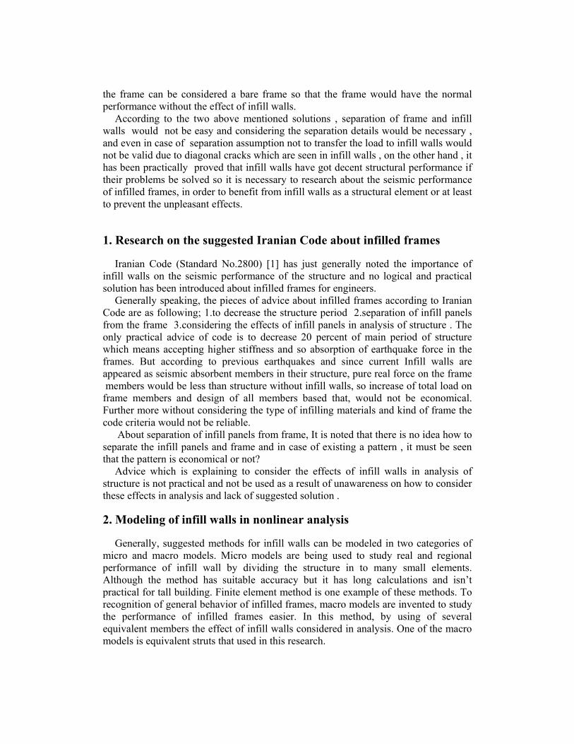
moments at the center of the joint, corresponding to the nominal flexural resistance of the beams farming in to the joint that have taken in to notice . The summary of designing results is listed in Table 1 to 3.
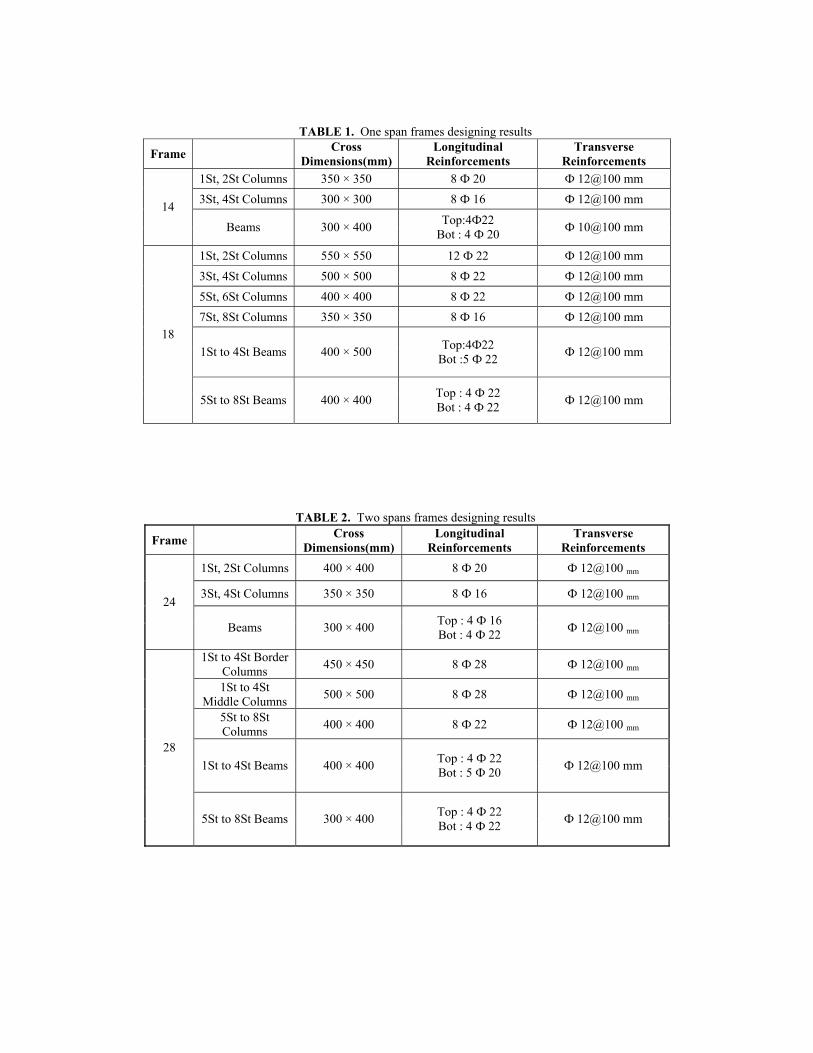
TABLE 1. One span frames designing results Frame Cross
Dimensions(mm) Longitudinal
Reinforcements Transverse
Reinforcements 1St, 2St Columns 350 × 350 8 Ф 20 Ф 12@100 mm 3St, 4St Columns 300 × 300 8 Ф 16 Ф 12@100 mm 14
Beams 300 × 400 Top:4Ф22 Bot : 4 Ф 20 Ф 10@100 mm
1St, 2St Columns 550 × 550 12 Ф 22 Ф 12@100 mm 3St, 4St Columns 500 × 500 8 Ф 22 Ф 12@100 mm 5St, 6St Columns 400 × 400 8 Ф 22 Ф 12@100 mm 7St, 8St Columns 350 × 350 8 Ф 16 Ф 12@100 mm
1St to 4St Beams 400 × 500 Top:4Ф22 Bot :5 Ф 22 Ф 12@100 mm
18
5St to 8St Beams 400 × 400 Top : 4 Ф 22 Bot : 4 Ф 22 Ф 12@100 mm
TABLE 2. Two spans frames designing results Frame Cross
Dimensions(mm) Longitudinal
Reinforcements Transverse
Reinforcements 1St, 2St Columns 400 × 400 8 Ф 20 Ф 12@100 mm
3St, 4St Columns 350 × 350 8 Ф 16 Ф 12@100 mm 24
Beams 300 × 400 Top : 4 Ф 16 Bot : 4 Ф 22 Ф 12@100 mm
1St to 4St Border Columns 450 × 450 8 Ф 28 Ф 12@100 mm
1St to 4St Middle Columns 500 × 500 8 Ф 28 Ф 12@100 mm
5St to 8St Columns 400 × 400 8 Ф 22 Ф 12@100 mm
1St to 4St Beams 400 × 400 Top : 4 Ф 22 Bot : 5 Ф 20 Ф 12@100 mm
28
5St to 8St Beams 300 × 400 Top : 4 Ф 22 Bot : 4 Ф 22 Ф 12@100 mm

TABLE 3. Three spans frames designing results
Frame Cross
Dimensions (mm)
Longitudinal Reinforcements
Transverse Reinforcements
1St, 2St Columns 400 × 400 8 Ф 20 Ф 12@100 mm
3St, 4St Columns 350 × 350 8 Ф 16 Ф 12@100 mm 34
Beams 300 × 400 Top : 4 Ф 18 Bot : 5 Ф 18 Ф 10@100 mm
1St to 4St Border Columns 500 × 500 12 Ф 20 Ф 10@100 mm
1St to 4St Middle Columns 550 × 550 12 Ф 22 Ф 12@100 mm
5St, 6St Columns 450 × 450 12 Ф 20 Ф 10@100 mm
7St, 8St Columns 400 × 400 8 Ф 16 Ф 12@100 mm
1St to 4St Beams 400 × 400 Top : 4 Ф 22 Bot : 5 Ф 22 Ф 10@100 mm
38
5St to 8St Beams 300 × 400 Top : 4 Ф 20 Bot : 5 Ф 20 Ф 10@100 mm
Infilled frames with the symbol of IFxy (Infilled Frame) and bare frames with
symbol of BFxy (Bare Frame) have been illustrated, where x is to define number of frame span and y is to define number of floors. Such as IF38 defines infilled frame 3 spans and 8 floors.
3.1 Masonry infill walls
Most of bricks are made of clay and made in the type of solid, ceramic, hollow bricks, where usually solid brick is used for infill frames. Approximate size of solid bricks is 220 * 110 * 55 mm and thickness of infill walls is considered 220 mm in considered frames. Paulay and Priestley (1992) equation has been used to calculate prism strength of masonry as following [11];
)''(
)''(''
cbtbu
jtbcbm ffU
ffff
αα
+
+= ;
bhj1.4
=α ; 5.1=u
U (22)
wheretb
f ' defines tension strength of the brick, cb
f ' Defines compressive strength of the brick,
jf ' defines mortar compression strength,
bh defines height of masonry unit
( 50 to 60 mm is considered for the height of a solid brick ), j is the mortar joint thickness and
uU is the stress non uniformity coefficient equal to 1.5 . Compressive
strength of the solid brick is 75 2cm
kg according to suggested number from Building
and Housing Research Center of Iran [12]. The tension strength of the solid bricks

may be determined as, (T. Paulay, M.J.N Priestly 1992) [11]:cbtb
ff '1.0' = , therefore,
=tb
f ' 7.52cm
kg .
In addition, the corresponding compression strength of the mortar is considered to be 50
2cmkg which is derived from experimental results carried out by Moghaddam (for
the cement-sand ratio of the mortar is 1:5) [13]. So regarding to mentioned numbers, and 15 mm for the mortar joint thickness and 60 mm for height of masonry unit; compression strength of a masonry prism is calculated as following;
=α 0.061 ; 5.1=u
U ; =m
f ' 44 =2cmkg 0.0043164
2mmKN
where this value have been used in this study. All other needed parameters in software for masonry infill walls are listed in Table 4.
3.2 Nonlinear dynamic analysis of frames
E-W record of Bam (2004) is used to analyze nonlinear dynamic analysis which is shown in fig. 5. Mentioned accelerogragh is calibrated by design base acceleration of relative high risk area (PGA=0.35g) and then has been used to analyze the frames. Damping is 5 percent of critical damping according to Iranian seismic code (Standard No. 2800) [1] for different kinds of structures despite higher damping values are reported where damping is considered up to 7 percent of critical damping for structures with have got infilled frame in all floors [14]. So averagely, damping is used as 6 percent of critical damping. Time history of roof displacement of considered frames are shown in Figs. 6 to 11.
3.2.1 Maximum displacement response of frames
Maximum displacement response of frames in BF and IF cases are shown in column diagram to compare the maximum displacement response of frames obtained from nonlinear dynamic analysis both of bare and infilled cases (Fig. 12).
It has been seen that the role of infill walls is noticeable in decrease of maximum displacement of frames after considering time history of roof displacement and maximum displacement in two cases of IF and BF, where averagely, 81 percent in 4 floors frames and 84 percent in 8 floors frames of maximum displacement of frame in IF than BF cases has decreased that illustrates the effect of infill walls to increase the stiffness of IF frames.
TABLE 4. Masonry materials properties
Parameter Description Amount FM Prism strength of masonry 0.00432
FMCR Cracking modulus of masonry 0.0002158 EPSM Strain corresponding to prism strength 0.002 VM Basic shear strength of masonry bed joints 0.000176
SIGMM Maximum allowable shear strength 0.0002158 CFM Coefficient of friction of frame-infill interface 0.3

-120
-70
-20
30
80
0 5 10 15 20
Time(sec)
Dis
p(m
m)
BF24IF24
-250-200-150-100-50
050
100150
0 5 10 15 20
Time(sec)
Dis
p(m
m)
BF28IF28
-150
-100
-50
0
50
100
0 5 10 15 20
Time(sec)
Dis
p(m
m)
BF34
IF34
-240-200-160-120-80-40
04080
120
0 5 10 15 20
Time(sec)
Dis
p(m
m)
BF38
IF38
-0.8
-0.6
-0.4
-0.2
0.0
0.2
0.4
0.6
0.8
1.0
0 15 30 45 60
Time (sec)
Acc
(g)
Bam E-W
-120-100-80-60-40-20
020406080
0 5 10 15 20
Time(sec)
Dis
p(m
m)
BF14IF14
-150
-100
-50
0
50
100
0 5 10 15 20
Time(sec)
Dis
p(m
m)
BF18IF18
FIGURE 5. Bam Earthquake E-W Component [12]
FIGURE 6. Time-history displacement FIGURE 7. Time-history displacement of roof in IF14, BF14 of roof in IF18, BF18
FIGURE 8. Time-history displacement FIGURE 9. Time-history displacement of roof in IF24, BF24 of roof in IF28, BF28
FIGURE 10. Time-history displacement FIGURE 11. Time-history displacement of roof in IF34, BF34 of roof in IF38, BF38

0
30
60
90
120
150
180
210
240
Disp
(mm
)
BF 104.56 142.97 113.95 211.56 120.3 215.3
IF 22.45 25.65 20.43 30.57 20.31 29.25
14 18 24 28 34 38
0
1
2
3
4
5
0 0.5 1 1.5
Drift Ratio(%)
Stor
y BF24IF24
0123456789
0 0.5 1 1.5
Drift Ratio(%)
Stor
y BF28IF28
0
1
2
3
4
5
0 0.5 1 1.5
Drift Ratio(%)
Stor
y BF14
IF14
0123456789
0 0.25 0.5 0.75 1
Drift Ratio(%)
Stor
y BF18IF18
FIGURE 12. Comparison of maximum displacement response of frames in nonlinear dynamic analysis
3.2.2 Drifts of floors
Drift of floors is a useful factor to analyze the seismic behavior of structure which identify the performance level of whole structure. Maximum drifts of floors in nonlinear dynamic analysis for considered frames are shown in Fig. 13.
It is obtained from maximum drifts of floors of frames that along increase of frame height effect of infill walls in controlling displacements of lower floors is decreased where the main cause is fracture of infill walls in these floors due to great shear force during lateral loading but on the other hand it is seen that in upper floors infill walls are able to control the displacements of floors that defines the pleasant effect of infill walls in upper floors.
FIGURE 13.a. Comparison of maximum drifts of floors in nonlinear dynamic analysis

0
1
2
3
4
5
0 0.5 1 1.5
Drift Ratio(%)
Stor
y BF34IF34
0123456789
0 0.5 1 1.5
Drift Ratio(%)
Stor
y BF38
IF38
FIGURE 13.b. Comparison of maximum drifts of floors in nonlinear dynamic analysis
4. Performance level of frames
The main goal of this study it to research about the effect of non connected masonry infill walls in seismic performance of RC moment resisting frames with high ductility, there fore performance level for each frame is defined regarding to nonlinear dynamic analysis . First step to define the performance level of structure is to choose suitable factor to evaluate the performance. One of the commonplace factors to define performance level of structures is drift of floors which is used to evaluate the performance level of whole structure. To reach this goal ATC 40 [15] criteria has been used. It is said in ATC 40 that if the maximum drift of structure is less than 1 percent performance level will be immediate occupancy (IO), if the drift is between 1 to 2 percent it will be damage control (DC), if the factor is 2 percent it will be Life safety (LS), and if the factor is 2 percent to 0.33 Vi/Pi (Vi = calculated shear force for storey i, Pi = gravity load ( including dead load and 20% of live load) in storey i) it will be structural stability (SS) [15]. The result of performance level of considered frames of IF and BF cases is shown in Table 5.
After defining performance level in IF and BF cases, it is resulted that when infill walls are not considered in nonlinear dynamic analysis (BF), performance level will be DC, but if infill walls are considered (IF) performance level will be IO, it could be said infill walls in performance level of RC moment resisting frame (even tall frames) have positive effect and cause the performance level of frames improved to IO.
Also another factor is used to determine the damage level called damage index which consider the maximum inelastic response and energy consumption during an earthquake. Damage index is calculated in different ways in IDARC that one of these ways is calculating damage index of whole structure according to modified Park & Ang model. Park & Ang index has been calibrated in 9 RC buildings after seeing the structural damages and it is said if the damage index of whole structure is more than 1 ; the structure is near destruction, if the damage index is between 0.4 to 1 then the structure damage is too much and it is not possible to repair the structure and if the damage index is less than 0.4 then the damage is average and the structure is repairable [2]. It is clear that damage of structure is less in lower damage index of whole of the structure and performance of the structure is more pleasant. According to this information damage index of whole of the structure in IF and BF cases is compared in Fig. 14.

0
0.02
0.04
0.06
0.08
DI
BF 0.039 0.043 0.045 0.062 0.045 0.059
IF 0.005 0.016 0.006 0.019 0.005 0.016
14 18 24 28 34 38
TABLE 5. Performance level of frames Frame 14 18 24 28 34 38
Maximum drift of BF (%) 1.2 0.93 1.25 1.3 1.34 1.22 Performance level of
frame DC IO DC DC DC DC
Maximum drift of IF (%) 0.31 0.19 0.32 0.19 0.31 0.18 Performance level of
frame IO IO IO IO IO IO
FIGURE 14. Comparison of damage index in IF and BF cases
Results
The goal of this study was to evaluate the effect of non connected masonry infill walls on seismic performance of RC moment resisting frames with high ductility where some moment resisting frames with high ductility in two cases of IF and BF were considered that the main results are as following ;
1. In all considered frames, the role of infill walls to control the displacement in lower floors is small that the main reason is fracture of infill walls in these floors due to great shear force as a result of lateral loading but on the other hand, infill walls in upper floors have been able to decrease the displacements of floors noticeably which illustrate the suitable performance of infill walls in upper floors.
2. In general study of performance level of frames with taking of maximum drift factor of floors in to consideration, it was understood that the performance level of frames in BF case is DC, but in IF case maximum drift in all frames is less than 1 percent which illustrate that performance level of frames in IF case is IO. So it could be said masonry infill walls play a noticeable role to optimize the performance level of RC moment resisting frames with high ductility.
3. By considering the whole damage index of BF frames based on modified Park & Ang model determined that damage level of RC moment resisting frames with high

ductility caused by earthquake is very low, which shows the suitable seismic performance of these frames. In the case of IF, damage level of the frame decreased noticeably and it is approximately negligible which is shows that infill walls could apply as seismic absorbent members and have positive effect on vulnerability decrease the frames.
4. By consideration of whole performance level of RC moment resisting frames with high ductility determined that in BF case whole performance level of the frame is DC and in IF case it is IO. On the other hand it is resulted that BF RC moment resisting frames with high ductility can satisfy Iranian seismic code (Standard No. 2800) which recommends that residential buildings should be life safe designed. Further more infilling the frames improve their performance level to IO.
REFERENCES
[1] Iranian code of practice for seismic resistant design of buildings (Standard No. 2800), 3rd edition, Building & Housing Research Center of Iran, 2004. [2] Reinhorn, A. M., Kunnath S. K., and Valles-Mattox R., (2004), IDARC 2D Version 6.0: users manual. Department of Civil Engineering, State University of New York at Buffalo. [3] Saneinejad, A., and Hobbs, B., 1995 "Inelastic Design of Infilled Frames", ASCE, Vol. 121, ST. 4, April, pp 634-649. [4] Baber, T. T., and Noori, M. N., "Random Vibration of Degrading Pinching Systems", Journal of Engineering Mechanics, Vol. 111, No. 8, 1985, pp. 1010-1026. [5] Reinhorn, A. M., Madam, A., Valles, R. E., Reichman, Y., Mander, J. B., 1995, Modeling of masonry infill panels for analysis of frame structures, Report NO. NCEER-95-018, National center for Earthquake Engineering Research, State University of New York at Buffalo. [6] Riddington, J. R., 1984, The influence of initial gaps on infilled frame behavior , Proc. ICE, Part 2, 77, Sept, pp 295-310. [7] Reinhorn AM et al. IDARC2D Version 6.0 - A computer program for the inelastic damage analysis of reinforced concrete buildings, State University of New York at Buffalo ( 2004). [8] Iranian Concrete Code, 3rd Edition, Management and Planning Organization of Iran, 2001. [9] Iranian Loading Code, Applied load to Structure, National collection of building codes bureau,
2002. [10] SAP2000, Linear and nonlinear static and dynamic analysis and design of structures. Ver.8.0,
Computers and Structures, Inc., Berkeley (CA, USA) (2002). [11] Paulay, T., Priestley M.J.N.,1992, Seismic Design of Reinforced Concrete and Masonry Buildings,
JOHN WILEY & SONS, INC . [12] BHRC, 2004, Building and Housing Research Center, http : // www.bhrc.gov.ir/. [13] Moghaddam, H. A, 2004, Lateral Load Behavior of Masonry Infilled Steel Frames with Repair
and Retrofit, Journal of Structural Engineering, ASCE, Vol. 130, NO 1, pp 56-63. [14] Moghaddam, H. A, Dowling . P. J. , 1987, The state of the Art in infiiled frames, ESEE report NO.
87-2, Civil Eng Dept, Imperial College, London. [15] ATC-40, 1996, Seismic Evaluation and Retrofit of concrete Buildings, prepared by the Applied
Technology Council, Redwood City, California 94065, Seismic Safety Commission State of California (Report NO. SSC 96-01).