mass casualty ventilator models: mcv100 &...
TRANSCRIPT

1
Mass Casualty Ventilator
Models: MCV100 & MCV100-B
Electrically Controlled Ventilator
St. Louis, MO 63110
Phone 314-771-2400
S168-560-001
Rev. B

2
Table of Contents:
Section Description Page
1 Product Description 3
2 Explanation of Warnings 3
3 Explanation of Abbreviations 4
4 Symbols 4
5 Specifications 5-6
6 Features 7
7 Operating the MCV100(-B) 8-11
8 Alarms 11-12
9 Power Connections 13
10 Battery Charging 13-14
11 Cleaning 14
12 Check Out Procedure 14-15
13 Maintenance 16-18
14 Accessories and Replacement Parts 20-21
15 Oxygen Cylinder Depletion Times 22
16 Table: Vt, flow, I:E Ratios, Approximate Vt Setting based on Height
23
17 Warranty 23
18 Applicable Standards 24
Models: MVC100 Mass Casualty Ventilator Basic Model MCV100-B Mass Casualty Ventilator with O2 Blender CAUTION: Federal law restricts this device to sale by or on the order of a physician. CAUTION: The Mass Casualty Ventilator should not be used on children with a weight of 20 kg (44 lbs) or less. Each MCV100 (-B) includes the following: 1 Ventilator 1 Patient Circuit 1 Power Cord 1 Oxygen Hose 2 Straps, Velcro 1 Instruction Manual

3
1. Product Description: The Mass Casualty Ventilator (MCV100 & MCV100-B) is an electrically controlled, portable emergency ventilator, which is designed to provide emergency respiratory support by means of a face mask or tube inserted into a patient’s airway. The MCV100 & MCV100-B delivers a time cycled constant flow breath. The inspiratory time is variable depending on the tidal volume selected. The breath volume is varied by changing the inspiratory time and the flow rate delivered to the patient. Various breaths per minute are achieved by varying the expiratory time. The MCV100 & MCV100-B can deliver breaths to the patient using internal compressors as well as an external high pressure gas source. The MCV100 & MCV100-B are intended for use on patients weighing greater than 20kg (44 lbs.). This ventilator is intended to be used in the environments associated with emergency medical services (EMS), inter-hospital transport and hospital facility
usage. The ventilator is intended to be used in temperatures of -18C to 50C (0F to
122F) and 5% to 95% RH non-condensing. The MCV100 & MCV100-B are intended to be used on one patient at a time. The unit can be reused after it has been cleaned and the single use patient circuit has been replaced. Biocompatibility testing has proven this unit safe for periods up to 14 days of continuous use. Results beyond this time are not known.
Warning: The MCV100 & MCV100-B are not MRI compatible.
Caution: Federal law restricts this device to sale by or on the order of a physician.
Caution: The MCV100 & MCV100-B should not be used on children with a weight of 20kg (44 lbs) or less.
2. Explanation of Warnings:
Warning: Potential injury to the patient exists.
Caution: Potential damage to the ventilator, breathing circuit or other equipment may result.
Warnings and cautions should be read and understood before operating the Autovent.

4
3. Explanation of Abbreviations:
Tv Tidal Volume
BPM Breaths per Minute
It Inspiratory Time
Psi Pounds per Square Inch
cm H2O Centimeters of Water
kpa Kilopascal
ml Milliliters
LPM Liters per minute
mm Millimeters
LED Light emitting diode
CPR Cardio Pulmonary Resuscitation
LPA Low pressure alarm
HPA High pressure alarm
RH Relative Humidity
4. Symbols:
Degree of protection against electric shock: Type BF
Caution, Consult accompanying documents
% Relative Humidity: 5 to 95%
Non-Condensing
Temperature Range: 0°F to 122°F Operating
-40°F to 140°F Storage
On/Off

5
5. Specifications: A. Gas Supply Pressure: 280 kPa (40.6 psi) to 600 kPa (87.0 psi) Oxygen
DISS. B. Breaths per Minute (BPM): Range: 8 to 20, Accuracy: ±10% C. Tidal Volume (Tv): Range: 200ml to 1200ml Accuracy: ±10% with 100% Oxygen or 100% Air, ±12% blended model(-B) D. Inspiratory Time (It):
Varies with tidal volume setting, the following table gives approximate inspiratory times: Tidal Volume Inspiratory Time (ml) (Seconds) 200 1.0 300 1.1 400 1.2 500 1.3
600 1.4 700 1.5 800 1.6 900 1.7 1000 1.8 1100 1.9 1200 2.0 E. Safety Pressure Relief: Adjustable from 5 cmH2O to a maximum between
60 and 80 cmH2O. The 60 cm H2O mark indicates the airway pressure will not exceed 60 cm H2O regardless of tidal volume setting.
F. Low Source Gas Alarm: Activates at 275 to 248kPa (40 to 36 psi) source pressure.
G. Electronic Alarms: High Airway Pressure Alarm Range 15 to 80 cm H2O High Airway Pressure Alarm Accuracy ± 5 % Low Airway Pressure Alarm Range 0 to 30 cm H2O Low Airway Pressure Alarm Accuracy ± 5 % Alarm Sound Level is greater than 60 decibels
H. Battery Life: Run time at room temperature 21°C (70+5°F), BPM=10, and Tidal Volume=600ml.
a. 100% O2: 20 hours (Approx 10 hours at 0°F (-18°C)) b. 60% O2: 20 hours (MCV100-B only) (Approx 10 hours at 0°F (-18°C)) c. 100% AIR: 7 hours (Approx 4 hours at 0°F (-18°C))
I. Oxygen Inlet Filter: 65 Micron sintered bronze. J. Burst Pressure: 145 psig (1000kPa) minimum through oxygen inlet. K. Leakage: The unit shall be designed so that oxygen is not allowed to leak
through any seals or fittings. L. Gauge: 0-99 cm H2O (0 – 9.8 kPa) accuracy ± 5% M. Inspiratory and Expiratory Resistance: 5 cm H2O (.5kPa) maximum N. Inadvertent PEEP: < 2 cm H2O O. Inadvertent Continuing Expiratory Pressure: < 2 cm H2O P. Dead Space: < 5.5% of minimum tidal volume

6
Q. Peak Inspiratory Flow: 100 LPM for 2 seconds R. Spontaneous Breath: Initiated at -2 cm H2O maximum S. Manual Breath: Delivers one set tidal volume T. Oxygen Blending: 60% ±12% oxygen with bender. U. Weight: 6.3 kg (14.0 lbs) V. Size: 88.9 x 261.1 x 292.1 mm (3.5 x 10.3 x 11.5 inches) W. Operating Conditions: -18°C to 50°C (0°F to 122°F) 5% to 95 % non-condensing relative humidity X. Storage Conditions: -40 to 60°C (-40 to 140°F) 5% to 95 % non-condensing relative humidity Y. Shipping Conditions: -40 to 60°C (-40 to 140°F) 5% to 95% non-condensing relative humidity Z. Electrical Rating:
Operating Voltage: 12 volts DC 5.0 amp current draw at 12 volts Input Voltage: 110 to 240 volts AC, 50 to 60 HZ 2 Amps max current draw. Replacement Fuses 2 amp 250 volt rating
AA. Connections: CGA V5 O2 DISS Input
ISO 5356 22 mm Output Latex Free: This product does not contain latex.

7
6. Features:
Item # Description Item # Description
1 Tidal Volume Control 10 Anti-Suffocation Valve
2 BPM Control 11 Patient Circuit Connection
3 LCD Display 12 Auxiliary 12V Power Inlet
4 Oxygen Connection 13 Power On/Off
5 Power On/Low Battery LED 14 AC Power Inlet
6 Manual Breath Button 15 Low Airway Pressure Alarm Adjustment
7 O2 concentration selector 16 High Airway Pressure Alarm Adjustment
8 Air Inlet/NBR Filter Connection 17 Alarm Silence Button
9 Adjustable Airway Pressure Relief Control
18 Alarm LED Indicator
4
2
1
6
7
8
11
10
17 16 15
3
13
12
18 5
9
14

8
7. Operating the MCV100(-B):
Warning: This device should only be operated by qualified personnel
under approved medical direction.
Warning: Use only as directed. Improper usage or unauthorized
modification of this product may result in user or patient injury.
The MCV100(-B) is intended to be used as an electrically powered emergency ventilator, which is designed to provide emergency respiratory support by means of a face mask or tube inserted into the patient’s airway. The ventilator is intended for use on patients weighing greater than 20kg (44lbs). The ventilator is intended to be
used in temperatures of -18C to 50C (0F to 122F) and 5% to 95% RH non-condensing. Prior to use, first read and understand the instruction manual, charge the battery and then follow the check out procedure in Section 12.
Connecting to an Oxygen Source: Located on the right side of the MCV100 is a diameter index safety system (DISS) fitting. Connect a 50 psi oxygen source with a minimum of 40 LPM flow capacity to this fitting.
Warning: Proper tidal volumes may not be provided with a gas source
not meeting the specified requirements on page 4.
Warning: This device operates with medical gases under pressure,
including oxygen. Do not use this device while smoking or near open
flames. Do not use on this device or operate near flammable materials.
Warning: Do not use on this device in the presence of flammable
anesthetics.
Warning: Verify that there are no noticeable leaks after connection to
the 50 PSI O2 source.
Caution: In order to provide optimal performance, check all gas
supplies to assure only medical grade gas is used.
The gas source may also be a high flow air/oxygen blender meeting the flow and pressure requirements. Use only the 100% oxygen setting on the MCV100, if using an external blender. This will ensure that the gas delivered from the ventilator has the same oxygen concentration as the gas delivered to it by the external blender.
Oxygen
Source
Connection

9
Connecting the patient breathing circuit: Located on the right side of the unit is a 22mm connection for a patient breathing circuit. Install the corrugated tubing over the connector so that it on securely. The tubing will not pull off easily when properly installed.
Warning: Do not use unapproved patient circuits as loss of
performance may result.
Warning: Do not occlude the anti-suffocation valve. This will prevent
the patient from getting outside air if spontaneously breathing.
Select the desired Breaths per Minute BPM: The MCV100 has a BPM range of 8 to 20 with an inspiratory time that automatically varies with the tidal volume setting. The American Heart Association Guidelines 2005 recommend a BPM rate of 8 to 12 for an adult and 12 to 20 for a child. These are recommendations and you should always follow your physicians or medical directors’ instructions.
Select the desired Tidal Volume: The MCV100 provides a Tidal Volume range of 200 – 1200ml. The inspiratory time will vary with tidal volume and is shown on the LCD display.
Select the desired Gas Mixture: Turn the gas selection knob to the desired gas selection. On the base model you will need to select 100% oxygen or air. On models equipped with a blender (MCV100-B) you can select 100% oxygen, a 60% Oxygen or air as the gas supply. On the 60% oxygen setting the ventilator uses a venturi blending system to mix ambient air with the medical oxygen source. The air setting draws in outside air and delivers it to the patient by the use of internal compressors. Let the unit cycle 3 times before connecting it to the patient to insure proper breaths are being delivered.
Warning: Do not use the Air or 60% Air/Oxygen mixture in areas
where the ambient air is not safe for breathing.
Anti-Suffocation valve
do not occlude!

10
Verify the Pressure Relief Setting: This unit has an adjustable pressure relief range with a marked setting of 60 cm H2O. At this setting, the airway pressure will not exceed 60 cm H2O regardless of vent settings. Adjustment above or below this marked setting will result in a corresponding higher or lower maximum airway pressure. The pressure relief setting will vary slightly with tidal volume setting. Always verify the pressure relief pressure after the vent settings have been selected. To check the actual relief pressure, block the end of the ventilator breathing circuit and observe the airway pressure reading on the LCD display. This will be the maximum airway pressure. You should hear an audible alarm as this maximum pressure is reached.
Warning: Preset tidal volumes may not be delivered when the
maximum pressure limit is reached. Inspiratory times will remain
constant, however no additional tidal volume will be delivered after the
pressure limit is reached.
Connect the patient breathing circuit to the patient: The patient breathing circuit has been designed to fit with an oxygen mask (22mm outside diameter) or endotracheal tube (15mm inside diameter). Follow the established guidelines for maintaining the patient’s airway.
Verify the patient is receiving good ventilation: Once the patient is connected to the ventilator the patient should be observed to make sure they have adequate chest rise and fall. The chest rise should be even and should return to a normal position. If the patient does not have adequate chest rise check the tidal volume setting, patient connections and examine the patient for a possible obstruction of the airway or other injury. The patient should be monitored to make sure they are receiving proper ventilation. The airway pressure LCD display should be observed to make sure the patient is receiving adequate positive pressure ventilation. If the LCD display reading is low during the delivery of a breath and the chest rise is also low, check the tidal volume setting, patient connections and examine the patient for a possible obstruction of the airway or other injury. The LCD display reading should also be observed to make sure it is not too high. Common numbers used in practice are a maximum of 20 cm H2O for and unprotected airway and 30 cm H2O for a protected airway. Higher pressures may be required based on the patient’s condition and you should always follow the physician’s instructions. A high reading with pressure limit alarm may indicate a blocked airway or a stiff lung.
Spontaneous Breathing by the Patient: Should the patient begin to breathe spontaneously the MCV100 will sense this breath and deliver the set tidal volume at the corresponding inspiratory time. The breath timing will be reset based on the selected BPM rate. For example, if 10 BPM was selected the next breath will be delivered 6 seconds after the start of the spontaneous breath.

11
The gas flow rate to the patient during a spontaneous breath is based on the tidal volume selection as shown in the following table. Should the patient demand exceed the gas flow rate, the additional demand will be supplied by ambient air. Ambient air is pulled in through an anti-suffocation valve located in the breathing circuit connection fitting.
Warning: Do not occlude the anti-suffocation valve. This will prevent
the patient from getting outside air if demand during spontaneous
breathing exceeds unit output.
Manual Breaths: Manual breaths may be delivered using the manual breath button. Each time this button is pushed the ventilator will deliver one breath with the set tidal volume. This button can be used to deliver breaths during CPR. The unit will deliver only one breath per the ventilator settings when the button is pushed. The button must be released and pushed again to deliver a second breath. The ventilator breath timing is reset when the button is pushed. 8. Alarms: The pneumatic pressure relief alarm is an audible alarm that is actuated when the safety pressure relief setting is reached. This pneumatic alarm indicates that the airway pressure has exceeded the maximum pressure relief setting and that gas has been released to prevent the pressure from reaching levels above this setting.
Warning: Preset tidal volumes may not be delivered when the
maximum pressure limit is reached. Inspiratory times will remain
constant, however no additional tidal volume will be delivered after the
pressure limit is reached.
The electronic alarms will give an audible and visual alert for the following occurrences:
Low Source Gas
High Airway Pressure
Low Airway Pressure
Tidal Volume Setting (ml)
Approx. Flow
(LPM)
200 12
400 20
600 25.7
800 30
1000 33.3
1200 36

12
The low source gas alarm is an audible (intermittent tone) and visual alarm that activates when the source gas pressure drops below 40 to 38 psi. This is an indication that the unit will stop functioning soon and may not be delivering proper tidal volumes. The alarm will clear when proper source gas pressure is restored for a minimum of 10 seconds. See low source gas alarm in section 6 for more information.
Warning: Preset tidal volumes may not be delivered when the low
source gas pressure is reached.
The high airway pressure alarm is an adjustable alarm that will activate if the pressure exceeds the selected pressure. This alarm operates independently from the pneumatic pressure relief alarm. This alarm can be set at a pressure from 15 to 80 cm H2O. This alarm may be used to monitor a change in the patient’s condition such as fluid collecting in the lungs or a partial obstruction of the airway. This alarm is automatically cleared when 12 seconds pass without a high airway pressure being detected. When activated, the alarm LED will blink red, the audible alarm will sound in a continuous tone, and the High Airway Alarm setting on the LCD display will blink. The low airway pressure alarm is an adjustable alarm that will activate if the airway pressure does not exceed a minimum value. This alarm can be set at a pressure from 0 to 30 cm H2O. This alarm may be used to indicate a potentially insufficient tidal volume or a patient disconnect. The airway pressure must exceed the low pressure set point at least once every 15 seconds. The alarm will clear when the airway pressure goes above the set point. When activated, the alarm LED will blink red, the audible alarm will sound in an intermittent tone or “beep”, and the Low Airway Alarm setting on the LCD display will blink. Alarm Silence Button – When there is an alarm the user may press the silence button. This will turn off the buzzer for 110 seconds as long as there are no other alarms. Pressing this button will not clear the alarm LED’s. The low battery alarm is indicated by the Power On/ Low Battery LED. The Power On/ Low Battery LED will light green when the unit is turned on and the battery level is good. When the battery becomes partially discharged, this LED will change from green to red. When the battery is critically low, this LED will flash red indicating the ventilator may stop functioning soon. When the low battery indicator is present the unit needs to plugged in for recharging the internal battery or may be connected to an auxiliary 12 volt power supply. Battery level is also indicated on the LED display.
Low Source Gas
High Airway Alarm
Low Airway Alarm
Battery Level
Indicator

13
9. Power Connections:
Warning: Grounding reliability can only be achieved when the
equipment is connected to a hospital grade receptacle.
AC Power Inlet and Auxiliary Power Connection A 110/240 Volt 50/60 Hz AC power source may be connected to the unit using the connector as shown above. The unit has a switching power supply inside it and automatically compensates to cover the full range of voltage and power frequencies. The unit will automatically charge the internal battery when connected to an AC power source. Plugging in the unit during breath delivery may affect the volume of the breath delivered. Plug the unit in between breaths. Connecting the auxiliary power source is done by first aligning the keyed connector with the keyed inlet on the unit and then inserting the connector into the inlet. Twisting the ring on the connector clockwise will then lock the connector to the unit. To remove the auxiliary power supply, twist the connector counterclockwise and then pull the connector straight out of the socket. Contact manufacturer for information on an approved auxiliary power source.
Warning: The MCV100 unit may reset when connecting or
disconnecting the auxiliary power. If this occurs, the MCV100 will
quickly and automatically return to normal operation.
Warning: Auxiliary power connection is keyed. Make sure that
connectors are properly aligned before insertion, do not force.
10. Battery Charging: If the internal battery has run down and the unit stops operating, the unit may be connected to AC to restore operation. The unit will charge automatically when connected to an AC power source. The unit will charge the battery only when necessary and can be left plugged in at all times. To keep the battery at full
AC POWER
INLET
IEC STYLE
AUXILIARY
POWER
CONNECTION

14
capacity, it is recommended to leave the unit plugged in at all times. If the auxiliary battery is plugged in the unit will only charge the auxiliary battery. The recharge time for the internal battery is less than 5 hours when the unit is off (the recharge time is approximately 10 hours when in use). 11. Cleaning: The MCV100(-B) should be cleaned after each use. To clean the ventilator, keep the gas supply hose on the unit to prevent contamination of the oxygen circuit.
Warning: Cleaning procedures should be performed in an environment
free of oil and petroleum based products.
The MCV100 has been designed to be water resistant but the unit cannot be submerged or sprayed down for cleaning. Wipe the unit down with a damp rag containing a mild cleaning solution to remove any residue from the surface. Once the residue has been removed the unit should be wiped with isopropyl alcohol or a cold disinfecting solution to kill bacteria. The unit should then be wiped down with water to remove any film left by the cold disinfecting solution. Make sure the unit is dry before putting the unit away. The following is a list of tested cleaning solutions: 1. Isopropyl Alcohol: 70% IPA 2. Alconox I Tablespoon Alconox to 1 Gallon H2O 3. Cetylcide: 2 Tablespoons Cetylcide to 1 Gallon H2O 4. Bleach: 10% Bleach in H2O
Warning: Do not attempt to clean and re-use single patient ventilation circuits as loss of performance may occur.
Dispose of single patient use items per local biohazard standards. 12. Check Out Procedure for the MCV100 & MCV100-B: The unit should be checked for proper operation before each use. This can be done after cleaning to prepare the unit for the next use..
Set the ventilator to the following settings: BPM = 10 Tidal Volume = 800 ml
Gas Type = 100% O2 General Operation Check:
1. Connect a 50 psi oxygen source to the unit, turn the power on and it should begin to cycle.

15
2. Using a watch count the number of breaths delivered in 1 minute (60 seconds).
a. confirm that between 9 and 11 breaths have been delivered. b. confirm that the inspiratory time is significantly shorter than the
expiratory time. (At the settings noted above, ventilator should provide a 1.6 second inspiratory time and a 4.4 second expiratory time.)
3. Set the pressure relief to 60 cm H2O and occlude the output fitting or vent
circuit output by placing your hand over the opening.
a. Confirm that the pressure on the gauge does not exceed 60 cm H20. b. Confirm that there is an audible squeak from the pressure relief valve,
signaling that the pressure relief has actuated.
4. Press and release the manual breath button and confirm that a breath is
triggered.
Alarm Mode Check: Set the low pressure alarm to 10 cm H2O and the high pressure alarm to 30 cm of H2O.
1. With the ventilator output open let the vent cycle for 20 seconds
a. Confirm that the low pressure alarm sounds and the low pressure indicator is displayed on the LCD screen.
2. Occlude the ventilator output with your hand for 20 seconds
a. Confirm that the low pressure alarm has cleared b. Confirm that the high pressure alarm sounds and the high pressure
indicator is displayed on the LCD screen.
3. Remove your hand from the ventilator output and let the vent cycle for 10 seconds
a. Confirm that the high pressure alarm has cleared.
4. Turn the source gas off and wait for the pressure to drop. a. Confirm that the low gas indicator is displayed on the LCD screen. b. Confirm that the low source gas alarm sounds
5. Visually inspect the anti-suffocation valve in the ventilator outlet fitting to verify
that it is laying flat against the inside of the fitting. Should the unit fail any of the tests contact Allied Healthcare Products, Inc. Service Department at 314-771-2400. Always store the ventilator in a clean dry place.

16
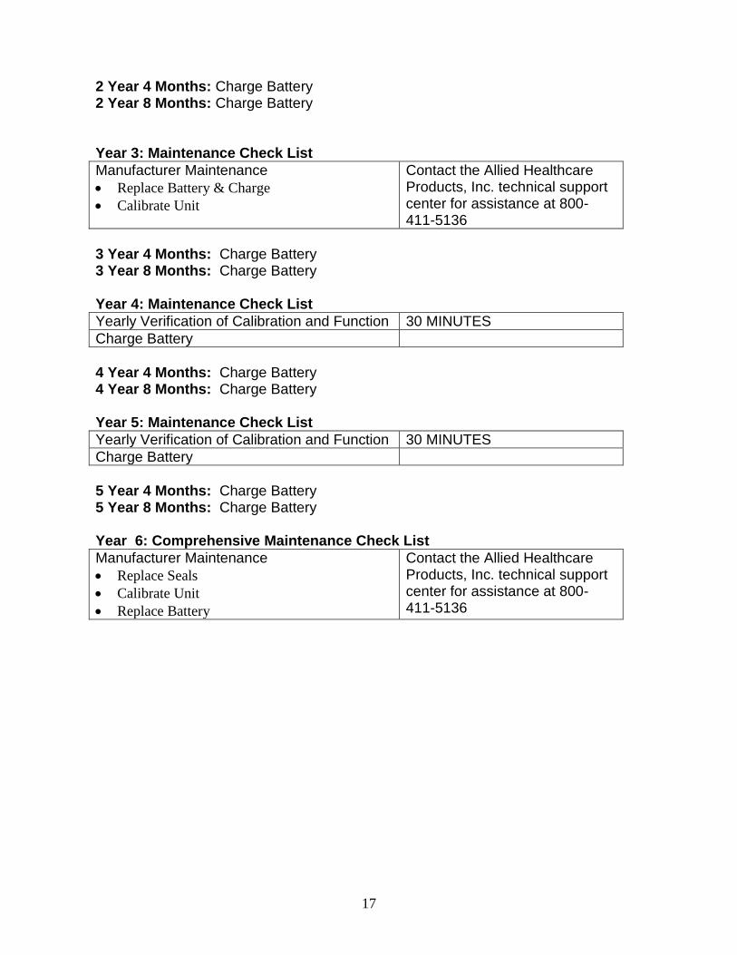
13. Maintenance: The following section provides information on basic maintenance as well as annual maintenance schedules and procedures for stockpiled ventilators. If this ventilator is to be used regularly, we recommend performing the Verification of Calibration and Function annually. Particle Filter Replacement: The MCV100(-B) contains a particle filter located inside the air inlet on the side of the unit. This filter cleans the ambient air drawn in by the compressors and also cleans the air used in the function of the blender. This filter should be checked every 4 months and changed if visibly dirty. To replace the filter, remove the protective screen by prying off with a dull flat tool. Once the screen is removed the filter can be removed and replaced. Battery Maintenance: The MCV100(-B) battery level should be checked every four months. If not kept on continuous charge, charge the battery at this time. If the battery does not reach full charge within 5 hours, the battery should be replaced at that time. Every three years, the battery in the unit should be replaced. This battery must be disposed of as required by local ordinances. Comprehensive Maintenance: Every six years, the unit should be sent to a qualified service center for a comprehensive maintenance. If problems are noted with this product, contact the Allied Healthcare Products, Inc. technical support center for assistance at 800-411-5136
Maintenance Requirements for Stock Piled MCV100 Ventilators 4 Months: Charge Battery (This 4 month battery charge protocol is only necessary if
the ventilator is stored without continuous charging.) 8 Months: Charge Battery Year 1: Maintenance Check List
Yearly Verification of Calibration and Function 30 MINUTES
Charge Battery
1 Year 4 Months: Charge Battery 1 Year 8 Months: Charge Battery Year 2: Maintenance Check List
Yearly Verification of Calibration and Function 30 MINUTES
Charge Battery
17
2 Year 4 Months: Charge Battery 2 Year 8 Months: Charge Battery Year 3: Maintenance Check List
Manufacturer Maintenance
Replace Battery & Charge
Calibrate Unit
Contact the Allied Healthcare Products, Inc. technical support center for assistance at 800-411-5136
3 Year 4 Months: Charge Battery 3 Year 8 Months: Charge Battery Year 4: Maintenance Check List
Yearly Verification of Calibration and Function 30 MINUTES
Charge Battery
4 Year 4 Months: Charge Battery 4 Year 8 Months: Charge Battery Year 5: Maintenance Check List
Yearly Verification of Calibration and Function 30 MINUTES
Charge Battery
5 Year 4 Months: Charge Battery 5 Year 8 Months: Charge Battery Year 6: Comprehensive Maintenance Check List
Manufacturer Maintenance
Replace Seals
Calibrate Unit
Replace Battery
Contact the Allied Healthcare Products, Inc. technical support center for assistance at 800-411-5136

18
Yearly Verification of Calibration and Function: Equipment Required Respical RT200 or equivalent ventilator calibrator
50 psi regulated Oxygen source
110 VAC, 60 Hz
Power Cord
Corrugated tubing
Procedure Connect the Oxygen source to the MCV100.
Use the power cord and connect the unit to 110 VAC, 60 Hz power source.
Connect the corrugated tubing the MCV100 outlet and the Respical high flow inlet
Set the tidal volume to 200 setting and turn the MCV100 on. Readjust the gas source to 50 psi if necessary.
Set the gas selection to 100% O2.
Adjust the BPM rate per the following table and note acceptable range:
BPM Acceptable Range
10 9 to 11
12 10.8 to 13.2
18 16.2 to 19.8
20 18 to 22
Set the BPM to 10 and the Tidal Volumes per the following table:
Tidal Volume Acceptable Range
200 180 to 220
400 360 to 440
600 540 to 660
800 720 to 880
1200 1080 to 1320
Set the gas selection to 100% Air. Retest the tidal volumes per the above table.
Set the gas selector to 60% O2 (Model MCV100-B only). Retest the tidal volumes per the above table.
To test the pressure relief, set the selector knob on 60 cm H2O. Remove the corrugated tubing from the outlet and occlude the outlet fitting with the palm of your hand. The airway pressure should not exceed 60 cm H20 and the audible alarm should sound.
To test the high airway pressure alarm, set the alarm to 40 cm H2O. The alarm LED and the buzzer should turn on and the HPA setting should flash on the LCD. To silence the alarm, hold the Alarm Silence button down for 3 seconds.
To test the low pressure/breath delivery alarm, set the alarm to 5 cm H2O. Open the patient outlet and the alarm/light will turn on in about 15 seconds.
Turn off the gas supply and the low gas alarm/light will turn on and the pumps will automatically activate in one minute.
If problems are noted with this product, contact the Allied Healthcare Products, Inc. technical support center for assistance at 800-411-5136

19
The following is a sample log that may be used for recording test records during Yearly Verification of Calibration and Function. Test Log Test Date:
BPM Acceptable Range Reading
10 9 to 11
12 10.8 to 13.2
18 16.2 to 19.8
20 18 to 22
Tidal Volume 100% O2
Acceptable Range
200 180 to 220
400 360 to 440
800 720 to 880
1200 1080 to 1320
Tidal Volume 100% Air
Acceptable Range
200 180 to 220
400 360 to 440
800 720 to 880
1200 1080 to 1320
Tidal Volume 60% O2
(MCV100-B ONLY)
Acceptable Range
200 176 to 224
400 352 to 448
800 704 to 896
1200 1056 to 1344
Pressure Relief High Pressure
Alarm
NO higher than 60 cmH20 Light
Buzzer
High Airway Pressure Alarm
Light Buzzer
Low Pressure Breath Delivery
Alarm
Light Buzzer
Low Source Gas Light Buzzer

20
14. Accessories and Replacement Parts:
Part Number Description Qty per Package
L599-180 3’ Vent Circuit, with Swivel 10
L599-190 3’ Vent Circuit, with swivel, exhalation filter 10
L599-130 3’ Vent Circuit , with swivel, adult mask 10
L599-140 3’ Vent Circuit, with swivel, adult mask, exhalation filter
10
L595161-10 Disposable Cuffed Oxygen Mask, Adult 10
L595162-10 Disposable Cuffed Oxygen Mask, Child 10
LPEEP PEEP Valve 12
MCM-001 Three Channel Oxygen Manifold 1
MCH-001 10 Ft. Oxygen Manifold Extension 1
L270-220 Oxygen Regulator 1
MCV-115V-CORD Replacement Power Cord w/ 115v plug 1
MCV-STRAP Replacement Kit, Velcro Straps 2
L535026 Replacement Oxygen Hose 6ft W/ DISS 1
MCV-FILTER Replacement Particle Filter 3
Velcro Hang Straps: Two Velcro hang straps have been included with your MCV100. The Velcro straps can be used to hang the ventilator from a horizontal support such as a bed rail. To attach the straps, simply insert the end of the strap through the handle hinges with the Velcro side down (Fig 1), loop the strap around a horizontal support and through the white buckle, and affix the Velcro strap to itself. Two straps should be used when hanging the MCV100 as shown below (Fig 2).
Figure 1 Figure 1

21
NBR Hazardous Environment Filter (not included): The air inlet fitting on the MCV100 has an internal 40 mm threaded connection per EN 148-1:1999. This is the standard thread connection for respiratory protective devices typically used by industry, law enforcement, and the military. This connection will accept air filters used in hazardous environments. To install, remove the air inlet screen and dust filter. The MCV100 will perform within manufacturer’s specifications when used with filters that are in compliance with requirements as specified in NIOSH-42 CFR Part 84. Refer to filter manufacturer’s specifications for gas type, filter life, and all other properties of the filter. Filter model FR-15-CBRN manufactured by 3M has been tested with this ventilator
Warning: Use of any filter with flow capacity of less than 40 LPM can degrade performance of the ventilator and may not provide filtration against the toxic environment for its intended use. Refer to manufacturer specifications for filter life.
Warning: Tighten filter in place securely to insure that the seal is air tight. Failure to tighten the filter may allow dangerous chemicals into the patient’s lungs.

22
15. Oxygen Cylinder Depletion Times: These times are approximate and assume full cylinder capacity and .5 liters per minute usage for the pneumatic module. Always monitor the cylinder pressure and low pressure alarm to make sure you do not run out of oxygen.
E Cylinder Capacity = 682 Liters Oxygen Capacity (4.6 Liters Water Capacity)
Breaths per Minute
Tidal Volume 8 9 10 12 14 15 18 20
1200 67 60 54 46 39 37
1000 80 72 65 54 47 44
800 98 88 80 67 58 54
600 127 115 104 88 76 72 60 54
500 149 135 123 104 90 85 72 65
400 180 163 149 127 111 104 88 80
300 225 206 189 163 143 135 115 104
200 293 274 256 225 200 189 163 149
Jumbo D Cylinder Capacity = 637 Liters Oxygen Capacity (4.0 Liters Water Capacity)
Breaths per Minute
Tidal Volume 8 9 10 12 14 15 18 20
1200 63 56 51 43 37 34
1000 75 67 61 51 44 41
800 92 82 75 63 54 51
600 119 107 97 82 71 67 56 51
500 139 126 115 97 85 79 67 61
400 168 152 139 119 104 97 82 75
300 210 192 177 152 134 126 107 97
200 274 256 239 210 187 177 152 139
D Cylinder Capacity = 414.6 Liters Oxygen Capacity
(2.8 Liters Water Capacity)
Breaths per Minute
Tidal Volume 8 9 10 12 14 15 18 20
1200 41 37 33 28 24 22
1000 49 44 39 33 29 27
800 60 54 49 41 35 33
600 77 70 63 54 46 44 37 33
500 91 82 75 63 55 52 44 39
400 109 99 91 77 67 63 54 49
300 137 125 115 99 87 82 70 63
200 178 166 155 137 122 115 99 91

23
16. Approximate Tidal Volume settings based on Height: APPROXIMATE SETTINGS BASED ON PATIENT HEIGHT
Tidal Volume (ml) 200 300 400 500 600 700 800 900 1000 1100 1200
Inspiratory Time (sec) 1 1.1 1.2 1.3 1.4 1.5 1.6 1.7 1.8 1.9 2
Flow Rate (LPM) 12 16.4 20.0 23.1 25.7 28.0 30.0 31.8 33.3 34.7 36.0
8 BPM = I:E (1 TO - ) 6.5 5.8 5.3 4.8 4.4 4.0 3.7 3.4 3.2 2.9 2.8
9 BPM = I:E (1 TO - ) 5.7 5.1 4.6 4.1 3.8 3.4 3.2 2.9 2.7 2.5 2.3
10 BPM = I:E (1 TO - ) 5.0 4.5 4.0 3.6 3.3 3.0 2.8 2.5 2.3 2.2 2.0
11 BPM = I:E (1 TO - ) 4.5 4.0 3.5 3.2 2.9 2.6 2.4 2.2 2.0 1.9 1.7
12 BPM = I:E (1 TO - ) 4.0 3.5 3.2 2.8 2.6 2.3 2.1 1.9 1.8 1.6 1.5
13 BPM = I:E (1 TO - ) 3.6 3.2 2.8 2.6 2.3 2.1 1.9 1.7 1.6 1.4 1.3
14 BPM = I:E (1 TO - ) 3.3 2.9 2.6 2.3 2.1 1.9 1.7 1.5 1.4 1.3 1.1
15 BPM = I:E (1 TO - ) 3.0 2.6 2.3 2.1 1.9 1.7 1.5 1.4 1.2 1.1 1.0
16 BPM = I:E (1 TO - ) 2.8 2.4 2.1 1.9 1.7 1.5 1.3 1.2 1.1 1.0 0.9
17 BPM = I:E (1 TO - ) 2.5 2.2 1.9 1.7 1.5 1.4 1.2 1.1 1.0 0.9 0.8
18 BPM = I:E (1 TO - ) 2.3 2.0 1.8 1.6 1.4 1.2 1.1 1.0 0.9 0.8 0.7
19 BPM = I:E (1 TO - ) 2.2 1.9 1.6 1.4 1.3 1.1 1.0 0.9 0.8 0.7 0.6
20 BPM = I:E (1 TO - ) 2.0 1.7 1.5 1.3 1.1 1.0 0.9 0.8 0.7 0.6 0.5
Height Male =((IBW-50)/2.3)+60 inches @10 ml/Kg (cm)
47
51 56 60 64 69 73 77 82 86 90
3'11" (119.4)
4' 3" (129.5)
4' 8" (142.2)
5' 0" (152.4)
5' 4" (162.6)
5' 9" (175.3)
6' 1" (185.4)
6' 5" (195.6)
6' 10" (208.3)
7’2” (218.4)
7’6” (228.6)
Height Female =((IBW-45.50)/2.3)+60 inches
49 53 58 62 66 71 75 79 84 88 92
@10 ml/Kg (cm)
4' 1" (124.5)
4' 5" (134.6)
4' 10" (147.3)
5' 2" (157.5)
5' 6" (167.6)
5' 11" (180.3)
6' 3" (190.5)
6' 7" (200.7)
7' 0" (213.4)
7’4” (223.5)
7’8” (233.7)
Ideal Body Weight Kg @10 ml/Kg
20.0 30.0 40.0 50.0 60.0 70.0 80.0 90.0 100.0 110.0 120.0
17. Warranty:
24
18. Applicable Standards:
This equipment has been tested and found to comply with the EMC limits for the Medical
Device Directive 93/42/ECN (EN 55011 and EN 60601-1-2). These limits are designed to
provide reasonable protection against harmful interference in a typical medical installation.
There is no guarantee that interference will not occur in a particular installation. If this
equipment does cause harmful interference with other devices, which can be determined by
turning the equipment off and on, the user is encouraged to try to correct the interference by
one or more of the following measures:
Reorient or relocate the receiving device
Increase the separation between the equipment
Consult the manufacturer or field service technician for help
The MCV 100 is intended to provide emergency respiratory support for children and adults. The
product is intended to meet the following safety and performance standards:
Performance and Safety Requirements
ASTM F920 – Performance and Safety Requirements for Resuscitators Intended for Use
with Humans
Electrical Safety Requirements
IEC 60601-1
Electromagnetic Compatibility
IEC 60601-1,-2
Biocompatibility Requirements
ISO 10993 – Physiochemical Tests for Plastics
US Pharmacopeia – Class VI
ISO 10993-1
Transport and Storage Requirements
MIL-STD-810E – Shock, Vibration, and Storage Requirements
IEC 60068-2-27 – Shock, Vibration, and Storage Requirements
IEC 60068-2-6 – Shock, Vibration, and Storage Requirements
IEC 60068-2-34 – Shock, Vibration, and Storage Requirements
The above listing of standards is not intended to be a complete listing of standards reviewed
and tested during the development of this product. It may also not reflect latest versions as
standards change. Allied Healthcare Products, Inc. regularly reviews the standards and
updates the products to ensure compliance as necessary.
For the latest revision of the instruction manual, please refer to the company website at
www.alliedhpi.com.
This manual is also available in other languages. Please call 314-771-2400 for more information on obtaining this manual in other languages. S168-560-001 REV. B