mass probar flowmeter - automaatika · 2015-03-12 · product data sheet 00813-0100-4762, ds-4011...
TRANSCRIPT

Product Data Sheet 00813-0100-4762, DS-4011
Mas
sP
roB
ar®
Mass ProBar ® Flowmeter
WHEN COMPARED WITH TRADITIONALDP OR VORTEX MASS FLOWMEASUREMENT, THE MASS PROBARFLOWMETER OUTPERFORMSAND OFFERS SIGNIFICANT COSTREDUCING BENEFITSREDUCED INSTALLATION COSTS
• Reduced programming time for DCS
• Installation costs cut by 90%
• Integrated electronics and sensorreduce installation costs and leak points
• Three process measurements witha single penetration
• Three process measurements combinedin one electronics package
• NEW 2-line display with eight selectablevariables, including flow and total
HIGH PERFORMANCE
• ±1.3% of mass flow rate accuracyover 8:1 flow turndown
• Dynamically compensated mass flow
• Liquids, gases, and steam
• 4–20mA output proportional tocompensated mass flow
• Digital HART protocol superimposedon the 4–20mA signal allows accessto mass flow, DP, process temperature,and gage or absolute pressure
REDUCED OPERATING COSTS
• Significantly lower permanent pressureloss than orifice or vortex meters
• Low maintenance costs, nomoving parts, non-plug design
HIGH RELIABILITY
• ISO 9001 company
• NIST traceable calibration
COMPLETE POINT SOLUTIONS™Rosemount Inc. Complete Point Solutions provides fully engineered measurement solutions, combining best product and practices for improved performance, reliability, and cost of ownership.
The capability of the world’s finest industrial measurement instrumentation is further increased by combining it with a premier offering of complimentary products. This system is engineered and assembled by Rosemount Inc. to make it easy for you to specify and order the correct equipment for your process measurement needs.
We complement our field instruments with a wide range of technologies; including, manifolds, primary elements, process flanges and seals, and temperature sensors and accessories.
Complete Point Solutions is designed to provide you with Best-in-Class equipment — allowing you to save on installation costs, and improve the reliability and capability of your process. Take advantage of our vast experience in process measurement, and start improving your process with Complete Point Solutions.
Flow-117
Flow-118
Mass ProBar ® Mass Flowmeter
Mass
ProB
ar®
MASSPROBAR FLOWMETER - - - - - - - - - - - - - - - - - - - - 120REINVENTING DP FLOW MEASUREMENT- - - - - - - - - - - - 120
Performance
MASSPROBAR FLOWMETER - - - - - - - - - - - - - - - - - - - - 121HOW THE MASS PROBAR FLOWMETER WORKS - - - - - - - 122THREEPROCESSVARIABLES MEASUREDWITH ONE SENSOR - 122CALIBRATED MASSPROBAR FLOWMETER- - - - - - - - - - - 122
Benef i ts
LOW COSTINSTALLATION - - - - - - - - - - - - - - - - - - - - - - 123LOW OPERATING COSTS- - - - - - - - - - - - - - - - - - - - - - - 124
Mass ProBar F lowmeter Conf igura t ion
REDUCED ENGINEERING TIME WITH OPTIONALENGINEERING ASSISTANTSOFTWARE - - - - - - - - - - - - - - 125BUILT-IN PHYSICAL PROPERTIESDATABASE - - - - - - - - - 125SAVES TIME AND MONEY - - - - - - - - - - - - - - - - - - - - - - 126OPTIONAL HART TRI-LOOP™ - - - - - - - - - - - - - - - - - - - 126
Features
FEATURE - - - - - - - - - - - - - - - - - - - - - - - - - - - - - - - - - 127BENEFIT - - - - - - - - - - - - - - - - - - - - - - - - - - - - - - - - - 127
Insta l la t ion(Fol l ow the PIPES Plan for Qual i ty Ins ta l la t ion. )
PIPE ORIENTATION - - - - - - - - - - - - - - - - - - - - - - - - - - - 128INSIDE PIPE DIAMETER - - - - - - - - - - - - - - - - - - - - - - - - 128PIPE PENETRATION- - - - - - - - - - - - - - - - - - - - - - - - - - - 128ELECTRONICSMOUNTING - - - - - - - - - - - - - - - - - - - - - - 129STRAIGHT RUN - - - - - - - - - - - - - - - - - - - - - - - - - - - - - 129
Sizing and How to Order
1. CHOOSE AMOUNTING METHOD - - - - - - - - - - - - - - - - 1312. CHOOSE ASENSORSIZE - - - - - - - - - - - - - - - - - - - - - 1323. VERIFY MODEL AND SENSORSIZE- - - - - - - - - - - - - - - 1334. CHOOSE THEMODEL OPTIONS - - - - - - - - - - - - - - - - - 1355. VERIFY PROCESS ANDPIPE INFORMATION - - - - - - - - - 136
Rosemount Inc.
Flow-119
Mas
sP
roB
ar®
O rder ing In format ion—Model MBR
MODEL MBR+15S/16S - - - - - - - - - - - - - - - - - - - - - - - 137MODEL MBR+25S/26S - - - - - - - - - - - - - - - - - - - - - - - 139MODEL MBR+35S/36S - - - - - - - - - - - - - - - - - - - - - - - 142MODEL MBR+45S/46S - - - - - - - - - - - - - - - - - - - - - - - 145
Ordering In format ion—Model MBF
MODEL MBF+15S/16S- - - - - - - - - - - - - - - - - - - - - - - - 153MODEL MBF+25S/26S- - - - - - - - - - - - - - - - - - - - - - - - 156MODEL MBF+25H/26H - - - - - - - - - - - - - - - - - - - - - - - 159MODEL MBF+25M/26M- - - - - - - - - - - - - - - - - - - - - - - 162MODEL MBF+35S/36S- - - - - - - - - - - - - - - - - - - - - - - - 165MODEL MBF+45S/46S- - - - - - - - - - - - - - - - - - - - - - - - 168MODEL MBF+45H/46H - - - - - - - - - - - - - - - - - - - - - - - 171MODEL MBF+45M/46M- - - - - - - - - - - - - - - - - - - - - - - 174
Ordering In format ion—Model MNT
MODEL MNT+10S- - - - - - - - - - - - - - - - - - - - - - - - - - - 182
Ordering In format ion—Model MNF
MODEL MNF+10S - - - - - - - - - - - - - - - - - - - - - - - - - - - 184MODEL MNF+10H - - - - - - - - - - - - - - - - - - - - - - - - - - 186MODEL MNF+10M - - - - - - - - - - - - - - - - - - - - - - - - - - 188
Ordering In format ion—Model MNW
MODEL MNW+10S - - - - - - - - - - - - - - - - - - - - - - - - - - 190
Ordering In format ion—Model MHT
MODEL MHT+15S- - - - - - - - - - - - - - - - - - - - - - - - - - - 198MODEL MHT+25S- - - - - - - - - - - - - - - - - - - - - - - - - - - 201MODEL MHT+35S- - - - - - - - - - - - - - - - - - - - - - - - - - - 204
Ordering In format ion—Model MHF
MODEL MHF+15S - - - - - - - - - - - - - - - - - - - - - - - - - - - 213MODEL MHF+25S - - - - - - - - - - - - - - - - - - - - - - - - - - - 216MODEL MHF+25H - - - - - - - - - - - - - - - - - - - - - - - - - - 219MODEL MHF+25M - - - - - - - - - - - - - - - - - - - - - - - - - - 222MODEL MHF+35S - - - - - - - - - - - - - - - - - - - - - - - - - - - 225MODEL MHF+45S - - - - - - - - - - - - - - - - - - - - - - - - - - - 228MODEL MHF+45H - - - - - - - - - - - - - - - - - - - - - - - - - - 231MODEL MHF+45M - - - - - - - - - - - - - - - - - - - - - - - - - - 234
Spec i f icat ions
FUNCTIONAL SPECIFICATIONS - - - - - - - - - - - - - - - - - - - 243PERFORMANCESPECIFICATIONS- - - - - - - - - - - - - - - - - - 244PHYSICAL SPECIFICATIONS - - - - - - - - - - - - - - - - - - - - - 245

M A S S P R O B A R ®
F l o w m e t e r
Flow-120
Mass
ProB
ar®
MASS PROBARFLOWMETERThe Mass ProBar flowmeter is a highly accurate insertion flowmeter. It measures mass flow rate for liquids, gases, and steam in line sizes from ½-inch to 72 inches. Mass ProBar is the combination of Dieterich Standard, Inc. Annubar® primary flow element technology and the 3095MV™ Multivariable™ transmitter from Rosemount Inc. into an integrated flowmeter.
Mass ProBar measures static pressure, temperature, and differential pressure (DP) with only one tap into the process line — offering significant installation cost savings. The multivariable electronics are capable of measuring all three process variables and calculating mass flow. The dynamic compensation provides a system accuracy of ±1.3% of mass flow rate over an 8:1 flow turndown—better performance than traditionally compensated DP flow measurement.
Dieterich Standard, Inc. has joined with Rosemount Inc. to provide flow solutions for process control and measurement.
Rosemount Inc. offers the leading technologies and highest quality in DP transmitters. The 3095MV multivariable transmitter accurately measures static pressure, temperature, DP, and calculates dynamically compensated mass flow. The 3095MV is the latest in multivariable technology and offers significant installation cost savings and performance.
As a member of the Rosemount Inc. team, Dieterich Standard, Inc. combines 3095MV-based electronics with the latest in DP primary technology—Diamond II+ Annubar primary flow element.
REINVENTING DPFLOW MEASUREMENTBy combining integrated electronics with insertion flowmeter technology, Mass ProBar provides the lowest total cost of any precision flowmeter. Installation costs are reduced by the measurement of three process variables through a small tap into an existing pipe and there is no plumbing required between the electronics and the sensing element. The multivariable electronics reduce hardware requirements. Due to the aerodynamic shape of the sensing element, the Mass ProBar flowmeter provides low operating costs. In addition, the insusceptibility of the sensor to warp, wear, and plugging and the stability of the electronics provide low maintenance costs.
When compared with traditional DP or vortex mass flow measurement, the Mass ProBar flowmeter outperforms and offers significant cost reducing benefits.

Rosemount Inc.
Flow-121
Mas
sP
roB
ar®
Performance
MASS PROBAR FLOWMETER
Accuracy ±1.3% ofMass Flow Rate, Turndown 8:1The Mass ProBar flowmeter provides high accuracy mass flow over a wide operating range by dynamically compensating flow equation variables in real time, including thermal expansion effects, density, and gas expansion effects. The fully compensated flow equation reduces the sources of traditional DP flow uncertainty, thereby providing a more accurate flow measurement.
FIGURE 1. Accuracy % Rate.
Compared to Non-CompensatedFlow MeasurementChanges in temperature, pressure, density, and specific gravity can cause significant errors in mass flow readings if not compensated. For example, an 11% shift in pressure or temperature can cause over a 5% error in mass flow reading.
FIGURE 2. Non-Compensated Flow Measurement.
Compared to TraditionalCompensated DP Flow MeasurementTraditionally, DP flow has been calculated in a DCS or flow computer using a simplified mass flow equation. In simplified DP mass flow measurements, a constant is used to represent many of the terms of the flow calculation.
The Mass ProBar flowmeter dynamically compensates for changes not only in density, but also in other terms that are considered constant in typical mass flow compensation. In fact, only the units conversion factor is constant. The other terms (thermal expansion factor, pipe ID, and gas expansion factor) are functions of static pressure and temperature. The simplified flow equation cannot compensate for changes in these terms resulting in unrecorded errors in the calculated flow rate. The Mass ProBar flowmeter uses a fully compensated equation for mass flow.
FIGURE 3. Compensated DP Flow Measurement.
%C
hang
e(T
,P,S
G,ρ
)
% Error in flow rate
Qmass = KFaaYaD2 DP (ρ).
Traditionally, a constant has been used for F aaYaD2.
C’ is not constant.Where C’ = NKF aaYaD2.
The Model 3095 dynamically calculates flow coefficients.
Traditional flow uncertainty is eliminated.
C’
C’
Flow
Flow

Flow-122
Mass ProBar ® Mass Flowmeter
Mass
ProB
ar®
FIGURE 4. Mass ProBar Flowmeter Diagram.
HOW THE MASS PROBARFLOWMETER WORKS
FIGURE 5. Mass ProBar Flowmeter.
THREE PROCESS VARIABLESMEASURED WITH ONE SENSOR
Temperature
The temperature is sensed through a standard 100 Ω platinum RTD mounted integral to the Mass ProBar sensor. An Annubar primary flow element chamber that is isolated from the process fluid is used as a thermowell, which enables removal and replacement of the RTD without removing the flowmeter or shutting down the process.
Static Pressure
Static pressure is measured off the high side of the Mass ProBar sensor. The Mass ProBar electronics calculate the portion of the high side pressure sensed that would be equal to the true pipe static pressure.
Differential Pressure
Differential pressure is sensed utilizing the patented Diamond II+ Annubar primary flow element DP sensing technology. The Mass ProBar flowmeter senses the entire flow profile and produces an accurate DP signal.
The Diamond II+ design provides a fixed separation point for linear, repeatable performance.
FIGURE 6. Diamond II+ Design.
CALIBRATED MASSPROBAR FLOWMETER
The Mass ProBar flowmeter can be calibrated over an 8:1 Reynold’s Number range to provide an improved accuracy. This patented technology eliminates “percent to full scale” errors associated with traditional compensated DP mass flow measurement.
Multivariable electronicsmeasure pressure,
temperature, differentialpressure, and calculate true
mass flow rates. Access to allmeasurements is available
through HART ® or through anoptional splitter that provides
access to all variablesvia 4-20mA loops .
Integral3-ValveManifold.
PatentedPak-Lok ®
mountingfor safeinstallationor optionalflangemounting.Proven Annubar primary flow
element technology senses theentire flow profile. An integral
RTD inside the sensor measurestemperature accurately.
Optionally, the sensor can becalibrated for higher accuracy.
The MassProBarflowmeter iseasilyconfiguredusing theWindows-based EAwhich controlsfluid propertiesfor 125 fluidsbased onAICHE. data
QmDP, P, T
Applicationspecificsolution isengineeredand down-loaded to theMass ProBarflowmeter.
The MassProBarflowmetersenses DP, T,and P throughone processtap andcomputes fullycompensatedmass flow.
Mass ProBarsensor with
integrated RTD.

Rosemount Inc.
Flow-123
Mas
sP
roB
ar®
Benefits
LOW COST INSTALLATION
Reduced Hardware Costs
Mass ProBar flowmeter offers a lower installation cost than traditional DP flow measurement devices. The fully integrated electronics and sensor eliminate fittings, tubing, valves, manifolds, adapters, and mounting brackets and reduce welding and installation time. In addition, the process line need only be tapped once to accurately measure temperature, pressure, and differential pressure. Installation time alone can be reduced up to 90% over traditional compensated mass flow measurement.
FIGURE 7. Flowmeter Hardware.
TABLE 1. Traditional vs. Mass ProBar Flowmeters.
Three Process VariablesMeasured with One Device
• One electronics package integrated into the sensing probe is all that is required to sense DP, temperature, and pressure.
• The Mass ProBar flowmeter reduces specification time, as one instrument specification replaces the four required for traditional compensated mass flow measurement.
• No DCS calculation time is required because mass flow rate is output as a 4-20 mA or through digital HART output.
FIGURE 8. Process Variables.
Compare the Mass ProBarFlowmeter Installation Costs
When compared to an orifice and vortex installation, the Mass ProBar flowmeter saves installation and hardware costs while offering superior accuracy and turndown. The larger the line size, the more value the Mass ProBar flowmeter offers.
FIGURE 9. Installation Costs.
Traditional Mass ProBar
Process tapsFittings & tubingValvesManifoldAdapter unionsTransmitter mountingWeldingLeak points
420512350 linear inches36
100Integral004 linear inches6
After Mass ProBarFlowmeter
Before Mass ProBarFlowmeter
DP
Pressure
COMPENSATEDMASS FLOW
Temperature
Mass ProBar Flowmeter
Vortex & Instruments
Orifice & Instruments
6 in. (150mm) pipe,steam 300# ANSI
Flowmeter or sensor
Mounting hardware
Transmitters
Manifold, valves,tees & bracket
Weld (mounting)
Fittings & Tubing
Wiring
Startup (Cal/Config)

Flow-124
Mass ProBar ® Mass Flowmeter
Mass
ProB
ar®
LOW OPERATING COSTS
Low Permanent Pressure Loss
The Mass ProBar flowmeter has the lowest pressure drop and operating cost of any DP or vortex flowmeter. The aerodynamic shape of the Mass ProBar sensor does not restrict the flow like the bluff body of a vortex shedder or the restrictive opening of an orifice plate.
FIGURE 10. Permanent Pressure Loss.Ref: 6”SCH40, 100# Steam, 11,300PPH
Energy Cost Saving
Permanent pressure loss can be converted directly into energy costs in the form of compressor costs for gas, electrical costs for pumping liquids, and fuel costs for generating steam. Energy savings increase with line size and flow rate. The payback time for a Mass ProBar flowmeter can be as short as six months just in energy savings. Contact your local salesperson for a cost savings analysis of your application.
FIGURE 11. Energy Costs.Ref: 6”SCH40, 100# Steam, 11,300PPH
Low Maintenance Costs
• Non-plug design
• No moving parts
• Combining three process variables and the mass flow calculation into one device reduces chance of mechanical breakdown
• Optional EA software and/or HART 275 handheld communicator allow easy maintenance and diagnostic functions
FIGURE 12. Non-Plug Design.
Reliability
• ISO 9001 certified
• Proven technology supplied by leading manufacturers
• 300 sales and service centers in 120 countries
• 90 years experience in flow measurement solutions
ÿþýüýýý
ÿüýýý
ÿþüýýý
ÿýý
ÿý
ÿþý
8”(200mm)
12”(300mm)
30”(750mm)(100mm)
4”
Mass ProBar Flowmeter
Vortex & Instruments
Orifice & Instruments
ISO
9001
Over 300Sales & ServiceCenters inÿþýüûúùø÷öõôó

Rosemount Inc.
Flow-125
Mas
sP
roB
ar®
Mass ProBar Flowmeter Configuration
REDUCED ENGINEERING TIME WITH OPTIONALENGINEERING ASSISTANT SOFTWARE
BUILT-IN PHYSICAL PROPERTIES DATABASE
EA includes an extensive physical properties database allowing calculation of density or compressibility tables, viscosity, and related fluid data for 125 fluids. These data are based on information published by American Institute of Chemical Engineers (AICHE). If desired, plant engineers can also enter their own fluids.
Engineering Assistant Physical Properties Database
Acetic Acid Cyclopropane Isopropanol n-Heptane 1-Decanol
Acetone Divinyl Ether Melamine n-Hexane 1-Dodecene
Acetonitrile Ethane Methane n-Octane 1-Dodecanol
Acetylene Ethanol Methanol n-Pentane 1-Heptanol
Acrylonitrile Ethylamine Methyl Acrylate Oxygen 1-Heptene
Air Ethylbenzene Methyl Ethyl Ketone Pentafluorothane 1-Hexene
Allyl Alcohol Ethylene Methyl Vinyl Ether Phenol 1-Hexadecanol
Ammonia Ethylene Glycol m-Chloronitrobenzene Propane 1-Octanol
Aniline Ethylene Oxide m-Dichlorobenzene Propadiene 1-Octene
Argon Fluorene Neon Pyrene 1-Nonanal
Benezene Formic Acid Neopentane Propylene 1-Nonanol
Benzaldehyde Formaldehyde Nitric Acid p-Nitroaniline 1-Pentadecanol
Benzyl Alcohol Furan Nitric Oxide Styrene 1-Pentanol
Biphenyl Helium-4 Nitrobenzene Sorbitol 1-Pentene
Carbon Dioxide Hydrazine Nitroethane Sulfer Dioxide 1-Undecanol
Carbon Monoxide Hydrogen Nitrogen Toluene 1,2,4-Trichlorobenzene
Carbon Tetrachloride Hydrogen Chloride Nitromethane Trichloroethylene 1,1,2-Trichloroethane
Chlorine Hydrogen Cyanide Nitrous Oxide Vinyl Acetate 1,1,2,2-Tetrafluoroethane
Chlorotrifluoroethylene Hydrogen Peroxide n-Butane Vinyl Acetylene 1,2-Butadiene
Chloroprene Hydrogen Sulfide n-Butanol Vinyl Chloride 1,3-Butadiene
Citric Acid Isobutane n-Butyraldehyde Vinyl Cyclohexane 1,3,5-Trichlorobenzene
Cycloheptane Isobutene n-Butyronitrile Water 1,4-Dioxane
Cyclohexane Isobutylbenzene n-Decane 1-Butene 1,4-Hexadiene
Cyclopentane Isopentane n-Dodecane 1-Decene 2-Methyl-1-Pentene
Cyclopentene Isoprene n-Heptadecane 1-Decanal 2,2-Dimethylbutane
The Mass ProBar flowmeter has extensive configuration capabilities and can be quickly and easily configured to measure many fluids. The Engineering Assistant (EA) software is a PC-based software package that allows comprehensive configuration of the Mass ProBar flowmeter. EA is easy to use, provides the technology to configure most mass flow processes, and includes a built-in physical property database. EA also provides the primary communications interface to the Mass ProBar flowmeter for maintenance and diagnostic functions. The handheld communicator HC275 can still be used as well for maintenance and diagnostic functions. FIGURE 13. Engineering Assistant Setup Screen.

Mass ProBar ® Mass Flowmeter
Flow-126
Mass
ProB
ar®
SAVES TIME AND MONEY
EA saves both time and money. Engineering time is saved because the plant engineer does not have to calculate viscosities, densities, flow equations, and related mass flow calculations. Market research estimates that users can expect to save four to six hours of engineering time per flow application with EA.
One of the dynamic capabilities of the EA is the compressibility and viscosity table. After identifying the liquid or gas and entering the operating pressure and pressure ranges, this table is automatically populated with a complete set of fluid data over the specified temperature/pressure range.
Another feature of EA is the configuration speed. With so much built-in to EA, a plant engineer can quickly get a process up and running. Later, after hands-on experience with the process, an engineer can easily modify the Mass ProBar configurations and density to improve product quality and to reduce by-product formation.
OPTIONAL HART TRI-LOOP™
Four Separate 4–20mA Outputs forP, T, DP, and Mass Flow
• Provides three additional 4–20 mA analog signals when installed with one Mass ProBar flowmeter
• Can be installed without disconnecting or disrupting existing Mass ProBar installations
• Each Tri-Loop analog output is electronically isolated from one another
• Provides three additional analog process variable measurements with no additional process penetrations
FIGURE 15. Hart Tri-Loop.
FIGURE 14. Engineering Assistant Steam Setup Screens.
CH 3 T
P
DP
MASS FLOW
CH 2
CH 1

Rosemount Inc.
Flow-127
Mas
sP
roB
ar®
Features
FEATURE BENEFIT
Integral RTDA three wire 100Ω platinum RTD is inserted into a sealed, pressure retaining thermowell in the sensor. Connections are made through an explosion-proof junction box. Designs by other vendors that do not provide a sealed thermowell are a potential hazard when removal of the RTD is required. The integral RTD eliminates hardware and installation costs.
A single pipe penetration allows measurement of mass flow, including temperature.
FIGURE 16. Integral RTD.
Pak-Lok MountingPak-Lok mounting seals and secures the Mass ProBar flowmeter firmly against the inside opposite wall simply and without high torque requirements. This design safely retains the sensor under high process pressures. It also provides additional structural support by placing the sensor in compression.
Allows safe and simple installation of Mass ProBar flowmeter.
FIGURE 17. Pak-Lok Mounting.
Direct Mount Integral ManifoldThe Mass ProBar electronics can be mounted directly to the sensor by means of either a three- or five-valve manifold. Upwards of 28 potential leak paths can be eliminated. The integral mount can be used in all fluids, except where the temperature is over 500 °F (260 °C).
Allows the electronics to be mounted directly to the sensor, eliminating costs and leak paths.
FIGURE 18. Direct MountIntegral Manifold.
Flanged Pipe SectionA good installation of the sensor is assured with the flanged pipe section option. The pipe can be made to any length for easy replacement of other piping components.
The Mass ProBar flowmeter can be mounted in a flanged pipe section for easy installation between existing flanges. FIGURE 19. Flanged Pipe Section.
Elbow MountMass ProBar flowmeter can be installed two pipe diameters from the centerline of an elbow and still provide good accuracy and repeatability: +3% without calibration.
Mass ProBar flowmeter can achieve good accuracy two pipe diameters from an elbow.
FIGURE 20. Elbow Mount.
Flo-Tap Mass ProBar FlowmeterThe Flo-Tap Mass ProBar flowmeter is perfectly suited to retrofit applications because the Flo-Tap flowmeter can be hot-tapped without interruption of the flow and without system shutdown.
Allows insertion and retraction without system shutdown.
FIGURE 21. Bi-DirectionalFlow Measurement.
Bi-Directional Flow MeasurementThe symmetrical design along with the controlled separation point provided by the exclusive diamond-shaped sensor means that a single Mass ProBar flowmeter is all that is required for bi-directional flow measurement.
A single Mass ProBar flowmeter can provide accurate bi-directional flow measurement.
Integrated Electronics Mounting
Flow-128
Mass ProBar ® Mass Flowmeter
Mass
ProB
ar®
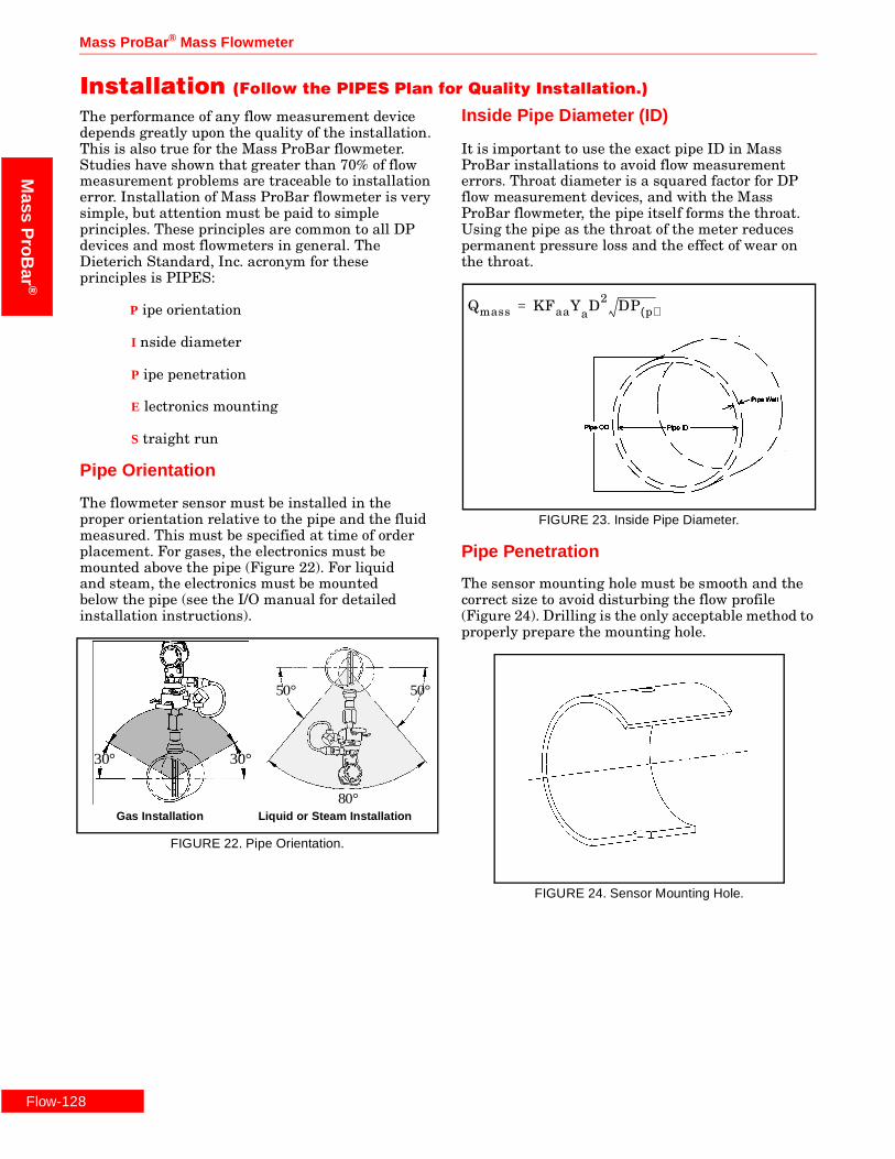
Installation (Follow the PIPES Plan for Quality Installation.)
The performance of any flow measurement device depends greatly upon the quality of the installation. This is also true for the Mass ProBar flowmeter. Studies have shown that greater than 70% of flow measurement problems are traceable to installation error. Installation of Mass ProBar flowmeter is very simple, but attention must be paid to simple principles. These principles are common to all DP devices and most flowmeters in general. The Dieterich Standard, Inc. acronym for these principles is PIPES:
P ipe orientation
I nside diameter
P ipe penetration
E lectronics mounting
S traight run
Pipe Orientation
The flowmeter sensor must be installed in the proper orientation relative to the pipe and the fluid measured. This must be specified at time of order placement. For gases, the electronics must be mounted above the pipe (Figure 22). For liquid and steam, the electronics must be mounted below the pipe (see the I/O manual for detailed installation instructions).
FIGURE 22. Pipe Orientation.
Inside Pipe Diameter (ID)
It is important to use the exact pipe ID in Mass ProBar installations to avoid flow measurement errors. Throat diameter is a squared factor for DP flow measurement devices, and with the Mass ProBar flowmeter, the pipe itself forms the throat. Using the pipe as the throat of the meter reduces permanent pressure loss and the effect of wear on the throat.
FIGURE 23. Inside Pipe Diameter.
Pipe Penetration
The sensor mounting hole must be smooth and the correct size to avoid disturbing the flow profile (Figure 24). Drilling is the only acceptable method to properly prepare the mounting hole.
FIGURE 24. Sensor Mounting Hole.
80°
50° 50°
30° 30°
Gas Installation Liquid or Steam Installation
Qmass KFaaYaD2 DP p( )=

Rosemount Inc.
Flow-129
Mas
sP
roB
ar®
Electronics Mounting
Mounting of the electronics can be integral or remote. Integral is preferred because of simplified installation, fewer leak points, faster response, and greater accuracy. Remote mounting is required when the process temperature is over 500 °F (260 °C), or when there is excessive vibration. Where remote mounting of the electronics is used, it is important that the orientation of the electronics relative to the sensor is correct. For gases, the electronics must be above the sensor and for liquids, below the sensor. It is critical to review the instruction manual on this topic and on commissioning.
FIGURE 25. Electronics Mounting.
Straight Run
To obtain published accuracy, sufficient straight run is required to produce a fully developed flow profile. Shorter lengths are possible, but accuracy will be affected. Consult the factory for further information.
Straight run requirements are also more stringent for achieving the highest accuracy. Recommended values shown are upstream straight run requirements. Four diameters are required downstream.
TABLE 2. Upstream Straight Run Requirements.
LocationWith
VanesWithoutVanes
After an elbow 8 10
Two elbows out of plane 8 28
After a modulating control valve 8 30
After an expansion 8 18
After a constriction 8 12

Flow-130
Mass ProBar ® Mass Flowmeter
Mass
ProB
ar®

Rosemount Inc.
Flow-131
Mas
sP
roB
ar®
Sizing and How to Order
1. CHOOSE A MOUNTING METHOD
MBR
FIGURE 26. Regular (Threaded Pak-Lok).
Mounting Method Threaded, Pak-Lok.Pipe Sizes2- to 72-in. (50 mm to 1800 mm).
MBF
FIGURE 27. Flanged.
Mounting MethodFlanged.Pipe Sizes2- to 72-in. (50 mm to 1800 mm).
MNT
FIGURE 28. Threaded In–Line.
Mounting MethodThreaded In-Line.Pipe Sizes½- to 2-in. (25 mm to 50 mm).
MNF
FIGURE 29. Flanged In–Line.
Mounting MethodFlanged In-Line.Pipe Sizes½- to 2-in. (25 mm to 50 mm).
MNW
FIGURE 30. In-Line Welded.
Mounting MethodIn-Line Welded.Pipe Sizes½ in. to 2 in. (25 mm to 50 mm).
MHT
FIGURE 31. High-Pressure Threaded Flo-Tap.
Mounting MethodThread Flo-Tap for pressure equivalent to ANSI Class 600 Flanges.Pipe Sizes2- to 72-in. (50 mm to 1800 mm).
MHF
FIGURE 32. High-Pressure Flanged Flo-Tap.
Mounting MethodFlanged Flo-Tap for pressure equivalent to ANSI Class 600 Flanges.Pipe Sizes2 in. to 72 in. (50 mm to 1800 mm).

Mass ProBar ® Mass Flowmeter
Flow-132
Mass
ProB
ar®
2. CHOOSE A SENSOR SIZE
TABLE 5. Sensors and Pipe Sizes.
Conversions for Verifications of Flows for Fluids Other than Air
Sensor Pipe Sizes
10 - MNT,MNW & MNF ½ in. to 2 in. (DIN 15 to DIN 50)
15/16 2 in. to 5 in. (DIN 50 to DIN 125)
25/26 4 in. to 42 in. (DIN 100 to DIN 1000)
35/36 10 in. to 72 in. (DIN 200 to DIN 1800)
45/46 16 in. to 72 in. (DIN 250 to DIN 1800)
1. To convert SCFM of air to SCFM of any other gas, divide the max SCFM by the square root of the specific gravity of the other gas.
2. To convert standard flow rates to actual flow rates (gas).
3. To convert U.S. to metric units.
SCFMotherSCFMair
SGother-----------------------------=
ACFMTf 460
oF+( )
Pf 35.302×( )-----------------------------------------XSCFM=
Tf = Flowing temperature, °FPf = Flowing pressure, psia
lb hr⁄ 2.205× kg hr⁄=
NM3
H SCFH35.37------------------=

Rosemount Inc.
Flow-133
Mas
sP
roB
ar®
3. VERIFY MODEL AND SENSOR SIZECompare maximum allowable flow to your maximum flow rates.
hw = maximum differential pressure in inches of water column 1.2 in. to 24 in. Sch 40
SCFM = maximum air flow in standard cubic feet per minute 30 in. to 42 in. Sch Std.
PPH = maximum steam flow in pounds per hour 48 in. to 72 in. Actual Id
At standard conditions: Air: 60°F at 14.73 psia
Steam flow at 100 lbs saturated (*hw calculated above 300 °F)
Nom.Pipe
Size (ininches)
Sensor 10
MNT MNF MNW
SCFM hw PPH SCFM hw PPH SCFM hw PPH
.5 180.52 1500 1521.2 180.52 1500 1521.2 180.52 1500 1521.2
.75 307.79 1500 2626.2 307.79 1500 2626.2 307.79 1500 2626.2
1 498.82 1500 4204.1 498.82 1500 4204.1 498.82 1500 4204.1
1.25 765.68 1180 6451.2 765.68 1180 6451.2 765.68 1180 6451.2
1.5 902.04 884 7654.8 902.04 884 7654.8 902.04 884 7654.8
2 1174.9 552 10070 1174.9 552 10070 1174.9 552 10070
Sensor 15 Sensor 16
MBR MBF MHF MBR MBF
SCFM hw PPH SCFM hw PPH SCFM hw PPH SCFM hw PPH SCFM hw PPH
2 1236.1 611 10672 502.91 84.3 4020.8 1555 967 13296 1236.1 611 10672 1322 699 11387
2.5 1531.9 451 13108 639.74 66.9 5111.1 1886.4 699 16190 1531.9 451 13108 1641 529 14161
3 2010.5 314 16935 859.71 50.5 6858.1 2408.7 478 20768 2010.5 314 16935 2175.3 380 18585
3.5 2408.7 246 20083 1046.1 41.7 8336.2 2852.6 369 24475 2408.7 246 20083 2639.5 305 22308
4 2816 199 23291 1237.1 35.1 9849.7 3331.3 294 28195 2816 199 23291 3126.9 253 26200
5 3723.8 137 30434 1663.7 25.6 13223 4364.9 195 36214 3723.8 137 30434 4213.3 180 34814
Sensor 25 Sensor 26
MBR MBF MHF MBR MBF
SCFM hw PPH SCFM hw PPH SCFM hw PPH SCFM hw PPH SCFM hw PPH
4 6263.45 1090 53745 2827.2 189 22801 7347.5 1500 62506 6263.4 1090 53745 7047.5 1380 60109
5 8148.5 747 70042 3798.1 138 30621 10066 1140 85564 8148.5 747 70042 9366.4 987 79961
6 10088 549 86951 4839.5 107 38950 12299 816 105070 10088 549 86951 11783 749 100880
8 14100 346 120070 6867.4 71.2 55057 16486 489 141940 14100 346 120070 16570 494 142640
10 18737 235 156510 9125.3 50.2 72913 21270 318 181400 18737 235 156510 22053 348 189510
12 23218 174 191570 11299 38 90092 26142 228 218740 23218 174 191570 27773 263 234550
14 25971 147 213040 12665 32.6 700870 29131 190 241690 25971 147 213040 31411 226 263140
16 30390 116 247520 14829 26.1 117930 33874 147 278210 30390 116 247520 37265 182 309040
18 34880 94.2 282610 17017 21.4 135190 38584 117 314580 34880 94.2 282610 43086 149 354430
20 39558 77.7 319230 19311 17.8 153270 43384 94.5 351770 39558 77.7 319230 49210 124 402350
24 48768 55.7 391340 23901 13 189480 52897 66 425730 48768 55.7 391340 61463 90.6 498150
30 65577 35.6 523390 32211 8.43 255050 70325 41.1 562200 65577 35.6 523390 83933 59.3 674620
36 80406 25.2 639850 39598 6.03 313340 85555 28.6 681520 80406 25.2 639850 103900 42.6 801100
42 95305 18.8 757040 47023 4.53 371910 100650 21 800040 95305 18.8 757040 123750 32 9869905

Mass ProBar ® Mass Flowmeter
Flow-134
Mass
ProB
ar®
3. VERIFY MODEL AND SENSOR SIZE (CONTINUED)
hw = maximum differential pressure in inches of water column 1.2 in. to 24 in. Sch 40
SCFM = maximum air flow in standard cubic feet per minute 30 in. to 42 in. Sch Std.
PPH = maximum steam flow in pounds per hour 48 in. to 72 in. Actual Id
At standard conditions: Air: 60°F at 14.73 psia
Steam flow at 100 lbs saturated (*hw calculated above 300 °F)
Nom.Pipe
Size (ininches)
Sensor 35 Sensor 36
MBR MBF MHF MBR MBF
SCFM hw PPH SCFM hw PPH SCFM hw PPH SCFM hw PPH SCFM hw PPH
8 20661 768 177160 9950.2 153 80562 24501 1080 208060 20661 768 177160 24387 1070 207160
10 26823 521 231030 13239 108 106760 31224 706 267130 26823 521 231030 32204 751 275060
12 32883 385 282890 16469 82.3 132370 37485 505 322440 32883 385 282890 39824 570 341660
14 37058 327 315630 18488 70.7 148340 41364 421 356720 37058 327 315630 44625 490 383740
16 43668 258 367050 21690 56.7 173600 48040 325 410760 43668 258 367050 52273 394 450890
18 50338 209 418930 24947 46.6 199290 55095 258 464420 50338 209 418930 60481 324 518860
20 57299 172 473010 28344 38.8 226080 62559 210 521700 57299 172 473010 69596 270 589880
24 71017 123 579670 36548 28.3 279370 76801 146 630850 71017 123 579670 87930 198 732800
30 96282 78.9 777460 47441 18.4 376620 103040 91.1 834910 96282 78.9 777460 121480 130 995350
36 118650 56 952310 58452 13.2 463420 125830 63.3 1012100 118650 56 952310 151120 93.2 1226100
42 141020 41.8 1127500 69564 9.95 551080 148640 46.6 1190200 141020 41.8 1127500 181070 70.3 1460000
48 163400 32.4 1326100 80662 7.76 649630 171330 35.7 1389500 163400 32.4 1326100 211020 54.9 1722900
60 208140 21.1 1676400 102920 5.1 825010 216230 22.8 1744100 208140 21.1 1676400 270800 36.1 2192800
72 253470 14.9 2033100 125280 3.61 1001700 261750 15.9 2094700 253470 14.9 2033100 330970 25.6 2664200
Sensor 45 Sensor 46
MBR MBF MHF MBR MBF
SCFM hw PPH SCFM hw PPH SCFM hw PPH SCFM hw PPH SCFM hw PPH
10 41878 1270 357030 20133 256 164060 45513 1500 385940 41878 1270 357030 45513 1500 385940
12 51142 940 437040 24994 195 203330 59210 1260 501370 51142 940 437040 61288 1350 517620
14 56913 797 487310 28092 168 228160 65325 1050 554920 56913 797 487310 68661 1160 581210
16 66100 630 567710 33012 135 267310 74858 808 638920 66100 630 567710 80698 939 685660
18 75353 511 648900 38019 111 306960 84461 642 723780 75353 511 648900 92738 774 790720
20 85108 422 734630 43418 93.2 349760 94565 521 813020 85108 422 734630 105460 648 902180
24 106480 303 903590 53975 68.2 433030 114620 364 987770 106480 303 903590 130590 475 1123000
30 146170 194 1213100 73415 44.7 586360 156190 226 1307400 146170 194 1213100 178800 313 1532300
36 181760 138 1489400 90648 32.1 722020 192700 157 1587000 181760 138 1489400 226020 226 1897800
42 217210 103 1764700 108240 24.3 860600 229510 116 1871500 217210 103 1764700 273660 171 2266000
48 251110 78.8 2061800 125770 19 1014200 265390 88.6 2183700 251110 78.8 2061800 321370 134 2680200
60 321930 51.5 2615700 160730 12.5 1290800 337470 56.8 2744300 321930 51.5 2615700 416410 88.4 3421600
72 392880 36.3 3171000 195900 8.86 1568100 408770 39.4 3301600 392880 36.3 3171000 511830 62.8 4161900

Rosemount Inc.
Flow-135
Mas
sP
roB
ar®
4. CHOOSE THE MODEL OPTIONS
Model Numbers Description Page Numbers
Standard Models: Line sizes 2 inches and larger
MBR+15/16S Mass ProBar Flowmeter—Regular (Threaded, Pak-Lok), SST page 137
MBR+25/26S Mass ProBar Flowmeter—Regular (Threaded, Pak-Lok), SST page 139
MBR+35/36S Mass ProBar Flowmeter—Regular (Threaded, Pak-Lok), SST page 142
MBR+45/46S Mass ProBar Flowmeter—Regular (Threaded, Pak-Lok), SST page 145
MBF+15/16S Mass ProBar Flowmeter—Flanged, SST page 153
MBF+25/26S Mass ProBar Flowmeter—Flanged, SST page 156
MBF+25/26H Mass ProBar Flowmeter—Flanged, Hastelloy–C page 159
MBF+25/26M Mass ProBar Flowmeter—Flanged, Monel page 162
MBF+35/36S Mass ProBar Flowmeter—Flanged, SST page 165
MBF+45/46S Mass ProBar Flowmeter—Flanged, SST page 168
MBF+45/46H Mass ProBar Flowmeter—Flanged, Hastelloy–C page 171
MBF+45/46M Mass ProBar Flowmeter—Flanged, Monel page 174
In–Line Models: Line sizes ½-inch to 2 inches
MNT+10S Mass ProBar Flowmeter—In-Line Threaded, SST page 182
MNF+10S Mass ProBar Flowmeter—In-Line Flanged, SST page 184
MNF+10H Mass ProBar Flowmeter—In-Line Flanged, Hastelloy–C page 186
MNF+10M Mass ProBar Flowmeter—In-Line Flanged, Monel page 188
MNW+10S Mass ProBar Flowmeter—In-Line Butt Weld, SST page 190
Flo–Tap Models
MHT+15S Mass ProBar Flowmeter—Threaded Flo-Tap, SST page 198
MHT+25S Mass ProBar Flowmeter—Threaded Flo-Tap, SST page 201
MHT+35S Mass ProBar Flowmeter—Threaded Flo-Tap, SST page 204
MHF+15S Mass ProBar Flowmeter—Flanged Flo-Tap, SST page 213
MHF+25S Mass ProBar Flowmeter—Flanged Flo-Tap, SST page 216
MHF+25H Mass ProBar Flowmeter—Flanged Flo-Tap, Hastelloy–C page 219
MHF+25M Mass ProBar Flowmeter—Flanged Flo-Tap, Monel page 222
MHF+35S Mass ProBar Flowmeter—Flanged Flo-Tap, SST page 225
MHF+45S Mass ProBar Flowmeter—Flanged Flo-Tap, SST page 228
MHF+45H Mass ProBar Flowmeter—Flanged Flo-Tap, Hastelloy–C page 231
MHF+45M Mass ProBar Flowmeter—Flanged Flo-Tap, Monel page 234
Flow-136
Mass ProBar ® Mass Flowmeter
Mass
ProB
ar®
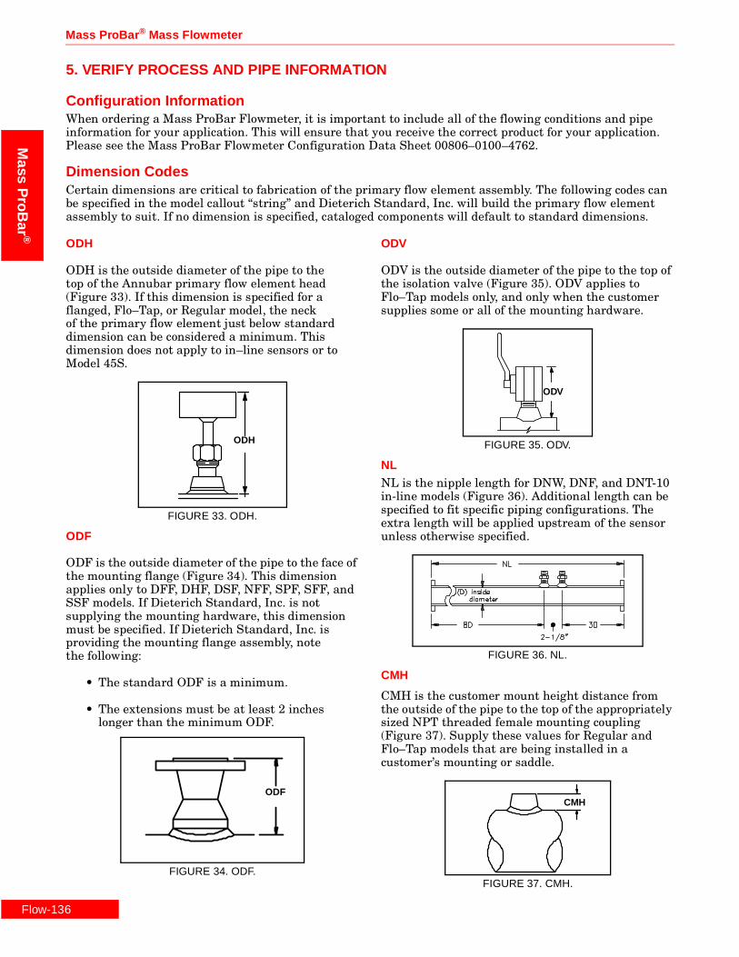
5. VERIFY PROCESS AND PIPE INFORMATION
Configuration InformationWhen ordering a Mass ProBar Flowmeter, it is important to include all of the flowing conditions and pipe information for your application. This will ensure that you receive the correct product for your application. Please see the Mass ProBar Flowmeter Configuration Data Sheet 00806–0100–4762.
Dimension CodesCertain dimensions are critical to fabrication of the primary flow element assembly. The following codes can be specified in the model callout “string” and Dieterich Standard, Inc. will build the primary flow element assembly to suit. If no dimension is specified, cataloged components will default to standard dimensions.
ODH
ODH is the outside diameter of the pipe to the top of the Annubar primary flow element head (Figure 33). If this dimension is specified for a flanged, Flo–Tap, or Regular model, the neck of the primary flow element just below standard dimension can be considered a minimum. This dimension does not apply to in–line sensors or to Model 45S.
FIGURE 33. ODH.
ODF
ODF is the outside diameter of the pipe to the face of the mounting flange (Figure 34). This dimension applies only to DFF, DHF, DSF, NFF, SPF, SFF, and SSF models. If Dieterich Standard, Inc. is not supplying the mounting hardware, this dimension must be specified. If Dieterich Standard, Inc. is providing the mounting flange assembly, notethe following:
• The standard ODF is a minimum.
• The extensions must be at least 2 inches longer than the minimum ODF.
FIGURE 34. ODF.
ODV
ODV is the outside diameter of the pipe to the top of the isolation valve (Figure 35). ODV applies to Flo–Tap models only, and only when the customer supplies some or all of the mounting hardware.
FIGURE 35. ODV.
NL
NL is the nipple length for DNW, DNF, and DNT-10 in-line models (Figure 36). Additional length can be specified to fit specific piping configurations. The extra length will be applied upstream of the sensor unless otherwise specified.
FIGURE 36. NL.
CMH
CMH is the customer mount height distance from the outside of the pipe to the top of the appropriately sized NPT threaded female mounting coupling (Figure 37). Supply these values for Regular and Flo–Tap models that are being installed in a customer’s mounting or saddle.
FIGURE 37. CMH.
ODH
ODF
ODV
CMH
Rosemount Inc.
-137
Mas
sP
roB
ar®
Flow
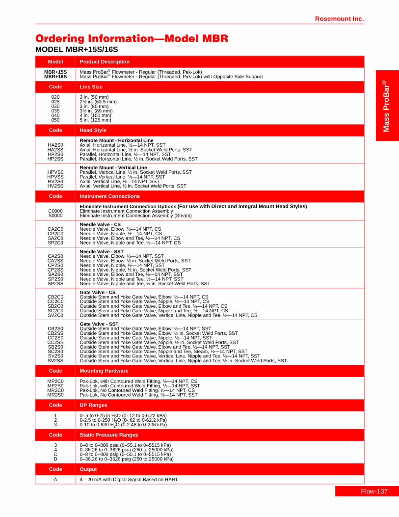
Ordering Information—Model MBRMODEL MBR+15S/16S
Model Product Description
MBR+15SMBR+16S
Mass ProBar® Flowmeter - Regular (Threaded, Pak-Lok)Mass ProBar® Flowmeter - Regular (Threaded, Pak-Lok) with Opposite Side Support
Code Line Size
020025030035040050
2 in. (50 mm)2½ in. (63.5 mm)3 in. (80 mm)3½ in. (89 mm)4 in. (100 mm)5 in. (125 mm)
Code Head Style
HA2S0HA2SSHP2S0HP2SS
Remote Mount - Horizontal LineAxial, Horizontal Line, ½—14 NPT, SSTAxial, Horizontal Line, ½ in. Socket Weld Ports, SSTParallel, Horizontal Line, ½—14 NPT, SSTParallel, Horizontal Line, ½ in. Socket Weld Ports, SST
HPVS0HPVSSHV2S0HV2SS
Remote Mount - Vertical LineParallel, Vertical Line, ½ in. Socket Weld Ports, SSTParallel, Vertical Line, ½—14 NPT, SSTAxial, Vertical Line, ½—14 NPT, SSTAxial, Vertical Line, ½ in. Socket Weld Ports, SST
Code Instrument Connections
C0000S0000
Eliminate Instrument Connection Options (For use with Direct and Integral Mount Head Styles)Eliminate Instrument Connection AssemblyEliminate Instrument Connection Assembly (Steam)
CA2C0CP2C0SA2C0SP2C0
Needle Valve - CSNeedle Valve, Elbow, ½—14 NPT, CSNeedle Valve, Nipple, ½—14 NPT, CSNeedle Valve, Elbow and Tee, ½—14 NPT, CSNeedle Valve, Nipple and Tee, ½—14 NPT, CS
CA2S0CA2SSCP2S0CP2SSSA2S0SP2S0SP2SS
Needle Valve - SSTNeedle Valve, Elbow, ½—14 NPT, SSTNeedle Valve, Elbow, ½ in. Socket Weld Ports, SSTNeedle Valve, Nipple, ½—14 NPT, SSTNeedle Valve, Nipple, ½ in. Socket Weld Ports, SSTNeedle Valve, Elbow and Tee, ½—14 NPT, SSTNeedle Valve, Nipple and Tee, ½—14 NPT, SSTNeedle Valve, Nipple and Tee, ½ in. Socket Weld Ports, SST
CB2C0CC2C0SB2C0SC2C0SV2C0
Gate Valve - CSOutside Stem and Yoke Gate Valve, Elbow, ½—14 NPT, CSOutside Stem and Yoke Gate Valve, Nipple, ½—14 NPT, CSOutside Stem and Yoke Gate Valve, Elbow and Tee, ½—14 NPT, CSOutside Stem and Yoke Gate Valve, Nipple and Tee, ½—14 NPT, CSOutside Stem and Yoke Gate Valve, Vertical Line, Nipple and Tee, ½—14 NPT, CS
CB2S0CB2SSCC2S0CC2SSSB2S0SC2S0SV2S0SV2SS
Gate Valve - SSTOutside Stem and Yoke Gate Valve, Elbow, ½—14 NPT, SSTOutside Stem and Yoke Gate Valve, Elbow, ½ in. Socket Weld Ports, SSTOutside Stem and Yoke Gate Valve, Nipple, ½—14 NPT, SSTOutside Stem and Yoke Gate Valve, Nipple, ½ in. Socket Weld Ports, SSTOutside Stem and Yoke Gate Valve, Elbow and Tee, ½—14 NPT, SSTOutside Stem and Yoke Gate Valve, Nipple and Tee, Steam, ½—14 NPT, SSTOutside Stem and Yoke Gate Valve, Vertical Line, Nipple and Tee, ½—14 NPT, SSTOutside Stem and Yoke Gate Valve, Vertical Line, Nipple and Tee, ½ in. Socket Weld Ports, SST
Code Mounting Hardware
MP2C0MP2S0MR2C0MR2S0
Pak-Lok, with Contoured Weld Fitting, ½—14 NPT, CSPak-Lok, with Contoured Weld Fitting, ½—14 NPT, SSTPak-Lok, No Contoured Weld Fitting, ½—14 NPT, CSPak-Lok, No Contoured Weld Fitting, ½—14 NPT, SST
Code DP Ranges
123
0-.5 to 0-25 in H2O (0-.12 to 0-6.22 kPa)0-2.5 to 0-250 H2O (0-.62 to 0-62.2 kPa)0-10 to 0-830 H2O (0-2.48 to 0-206 kPa)
Code Static Pressure Ranges
34CD
0–8 to 0–800 psia (0–55.1 to 0–5515 kPa)0–36.26 to 0–3626 psia (250 to 25000 kPa)0–8 to 0–800 psig (0–55.1 to 0–5515 kPa)0–36.26 to 0–3626 psig (250 to 25000 kPa)
Code Output
A 4—20 mA with Digital Signal Based on HART

Flow-1
Mass ProBar ® Mass Flowmeter
Mass
ProB
ar®
Code Fill Fluid
12
SiliconeInert Fill
Code Housing Material
ABCDJKLM
Epoxy-Poly-Aluminum ½—14 NPTEpoxy-Poly-Aluminum CM 20Epoxy-Poly-Aluminum PG 13.5Epoxy-Poly-Aluminum G½316 SST ½—14 NPT316 SST CM 20316 SST PG 13.5Epoxy-Poly-Aluminum G½
Code Opposite Side Support (Required for Model 16S ONLY)
MS2C0MS2CWMS2S0MS2SW
Contoured Weld Fitting and Plug, ½—14 NPT, CSContoured Weld Fitting and Plug, ½ in. Socket Weld Ports, CSContoured Weld Fitting and Plug, ½—14 NPT, SSTContoured Weld Fitting and Plug, ½ in. Socket Weld Ports, SST
Code Optional Auxiliary Mounting (Mounting alternatives for use when Contoured Weld Fitting is Not Specified in Mounting Hardware)
MT2CMT2SME2CME2AME2KME2PME2SNB20NC20ND20NE20NF20
Contoured Weld Fitting, ½—14 NPT, CSContoured Weld Fitting, ½—14 NPT, SSTWeld Coupling, ½—14 NPT, CSWeld Coupling, ½—14 NPT, AluminumWeld Coupling, ½—14 NPT, CopperWeld Coupling, ½—14 NPT, PVCWeld Coupling, ½—14 NPT, SSTSaddle, Double Strap, 2.35-2.56, ½—14 NPT, Iron (Model 15S only)Saddle, Double Strap, 2.41-2.91, ½—14 NPT, Iron (Model 15S only)Saddle, Double Strap, 2.97-3.54, ½—14 NPT, Iron (Model 15S only)Saddle, Double Strap, 4.14-4.80, ½—14 NPT, Iron (Model 15S only)Saddle, Double Strap, 5.94-6.70, ½—14 NPT, Iron (Model 15S only)
Code Optional Temperature Sensors (For Use with Remote Mount Head Styles.)
TRRTXR
Remote Thermowell and RTDRemote Thermowell and RTD, Explosion-Proof
Code Optional Optional Manifolds
35678
Model 305 Manifold Bolted to Transmitter5-Valve Manifold, CS5-Valve Manifold, SST3-Valve Manifold, CS3-Valve Manifold, SST
Code Optional Mounting Brackets
K Coplanar Bracket, 2 in., Pipe/Panel, SST Bolts
Code Optional Meters
1 LCD Meter (Rate and Total)
Code Optional Hazardous Location Certificates
ABCDFH
FM Explosion-Proof ApprovalFM Explosion-Proof and Intrinsic Safety ApprovalCSA Explosion-Proof ApprovalCSA Explosion-Proof and Intrinsic Safety ApprovalKEMA/CENELEC Intrinsic Safety ApprovalKEMA/CENELEC Explosion-Proof Approval
Code Optional Calibration
MZ
Lab Flow Calibration (Average K) (<10 in.)Special Calibration
Code Optional Quality Assurance
QA1Q21Q23Q29QJ2QM2QT1QT2QT8
Dieterich ProgramANSI B31.1ANSI B31.3NACE MR-0175-91Special Product DrawingASTM Material-Traceable (Sensor Only)Hydrostatic Test EP-4017Dye Penetrant ES-1012Extended Hydro EP-4046
Typical Model Number MBR+15S 030 HA2S0 CA2C0 MP2C0 1 3 A 1 A TRR 3 K
MODEL MBR+15S/16S
38

Rosemount Inc.
Mas
sP
roB
ar®
MODEL MBR+25S/26SModel Product Description
MBR+25SMBR+26S
Mass ProBar® Flowmeter - Regular (Threaded, Pak-Lok)Mass ProBar® Flowmeter - Regular (Threaded, Pak-Lok) with Opposite Side Support
Code Line Size
040050060080100120140160180200240300360420
4 in. (100 mm)5 in. (125 mm)6 in. (150 mm)8 in. (200 mm)10 in. (250 mm)12 in. (300 mm)14 in. (350 mm)16 in. (400 mm)18 in. (450 mm)20 in. (500 mm)24 in. (600 mm)30 in. (750 mm)36 in. (900 mm)42 in. (1066 mm)
Code Head Style
HADS0HADSBHADSNHAMS0HAPS0
Direct and Integral Mount Heads - Horizontal LineDirect Mount, with 5-Valve Manifold, Horizontal Line, SSTDirect Mount, with 5-Valve Manifold, B31.1, Horizontal Line, SSTDirect Mount, with 5-Valve Manifold, NACE, Horizontal Line, SSTIntegral, 3-Valve Manifold, Horizontal Line, SSTDirect Mount, No Manifold, Horizontal Line, SST
HATS0HATSBHATSDHATSN
Direct and Integral Mount Heads - Horizontal Line with RTDIntegral, 3-Valve Manifold, RTD, Horizontal Line, SSTDirect Mount, 5-Valve Manifold, RTD, B31.1, Horizontal Line, SSTDirect Mount, with 5-Valve Manifold, RTD, Horizontal Line, SSTDirect Mount, 5-Valve Manifold, RTD, NACE, Horizontal Line, SST
HVDS0HVDSBHVDSNHVMS0HVPS0
Direct and Integral Mount Heads - Vertical LineDirect Mount, with 5-Valve Manifold, Vertical Line, SSTDirect Mount, 5-Valve Manifold, B31.1, Vertical Line, SSTDirect Mount, 5-Valve Manifold, NACE, Vertical Line, SSTIntegral, 3-Valve Manifold, Vertical Line, SSTDirect Mount, No Manifold, Vertical Line, SST
HVTS0HVTSBHVTSDHVTSN
Direct and Integral Mount Heads - Vertical Line with RTDIntegral Mount, with 3-Valve Manifold, Vertical Line, SSTDirect Mount, 5-Valve Manifold, RTD, B31.1, Vertical Line, SSTDirect Mount, with 5-Valve Manifold, RTD, Vertical Line, SSTDirect Mount, 5-Valve Manifold, RTD, NACE, Vertical Line, SST
HA2S0HA2SSHP2S0HP2SS
Remote Mount - Horizontal LineAxial, Horizontal Line, ½—14 NPT, SSTAxial, Horizontal Line, ½ in. Socket Weld Ports, SSTParallel, Horizontal Line, ½—14 NPT, SSTParallel, Horizontal Line, ½ in. Socket Weld Ports, SST
HPVS0HPVSSHV2S0HV2SS
Remote Mount - Vertical LineParallel, Vertical Line, ½ in. Socket Weld Ports, SSTParallel, Vertical Line, ½—14 NPT, SSTAxial, Vertical Line, ½—14 NPT, SSTAxial, Vertical Line, ½ in. Socket Weld Ports, SST
Code Instrument Connections
C0000S0000
Eliminate Instrument Connection Options (For use with Direct and Integral Mount Head Styles)Eliminate Instrument Connection AssemblyEliminate Instrument Connection Assembly (Steam)
CA2C0CP2C0SA2C0SP2C0
Needle Valves - CSNeedle Valve, Elbow, ½—14 NPT, CSNeedle Valve, Nipple, ½—14 NPT, CSNeedle Valve, Elbow and Tee, ½—14 NPT, CSNeedle Valve, Nipple and Tee, ½—14 NPT, CS
CA2S0CA2SSCP2S0CP2SSSA2S0SP2S0SP2SS
Needle Valve - SSTNeedle Valve, Elbow, ½—14 NPT, SSTNeedle Valve, Elbow, ½ in. Socket Weld Ports, SSTNeedle Valve, Nipple, ½—14 NPT, SSTNeedle Valve, Nipple, ½ in. Socket Weld Ports, SSTNeedle Valve, Elbow and Tee, ½—14 NPT, SSTNeedle Valve, Nipple and Tee, ½—14 NPT, SSTNeedle Valve, Nipple and Tee, ½ in. Socket Weld Ports, SST
Flow-139

Flow-1
Mass ProBar ® Mass Flowmeter
Mass
ProB
ar®
Code Instrument Connections (For use with Direct and Integral Mount Head Styles) (Continued)
CB2C0CC2C0SB2C0SC2C0SV2C0
Gate Valve - CSOutside Stem and Yoke Gate Valve, Elbow, ½—14 NPT, CSOutside Stem and Yoke Gate Valve, Nipple, ½—14 NPT, CSOutside Stem and Yoke Gate Valve, Elbow and Tee, ½—14 NPT, CSOutside Stem and Yoke Gate Valve, Nipple and Tee, ½—14 NPT, CSOutside Stem and Yoke Gate Valve, Vertical Line, Nipple and Tee, ½—14 NPT, CS
CB2S0CB2SSCC2S0CC2SSSB2S0SC2S0SV2S0SV2SS
Gate Valve - SSTOutside Stem and Yoke Gate Valve, Elbow, ½—14 NPT, SSTOutside Stem and Yoke Gate Valve, Elbow, ½ in. Socket Weld Ports, SSTOutside Stem and Yoke Gate Valve, Nipple, ½—14 NPT, SSTOutside Stem and Yoke Gate Valve, Nipple, ½ in., Socket Weld Ports, SSTOutside Stem and Yoke Gate Valve, Elbow and Tee, ½—14 NPT, SSTOutside Stem and Yoke Gate Valve, Nipple and Tee, Steam, ½—14 NPT, SSTOutside Stem and Yoke Gate Valve, Vertical Line, Nipple and Tee, ½—14 NPT, SSTOutside Stem and Yoke Gate Valve, Vertical Line, Nipple and Tee, ½ in. Socket Weld Ports, SST
Code Mounting Hardware
MR4C0MR4S0MP4C0MP4S0
Pak-Lok, No Contoured Weld Fitting, 1—11.5 NPT, CSPak-Lok, No Contoured Weld Fitting, 1—11.5 NPT, SSTPak-Lok, with Contoured Weld Fitting, 1—11.5 NPT, CSPak-Lok, with Contoured Weld Fitting, 1—11.5 NPT, SST
Code DP Ranges
123
0-.5 to 0-25 in H2O (0-.12 to 0-6.22 kPa)0-2.5 to 0-250 H2O (0-.62 to 0-62.2 kPa)0-10 to 0-830 H2O (0-2.48 to 0-206 kPa)
Code Static Pressure Ranges
34CD
0–8 to 0–800 psia (0–55.1 to 0–5515 kPa)0–36.26 to 0–3626 psia (250 to 25000 kPa)0–8 to 0–800 psig (0–55.1 to 0–5515 kPa)0–36.26 to 0–3626 psig (250 to 25000 kPa)
Code Output
A 4—20 mA with Digital Signal Based on HART
Code Fill Fluid
12
SiliconeInert Fill
Code Housing Material
ABCDJKLM
Epoxy-Poly-Aluminum ½—14 NPTEpoxy-Poly-Aluminum CM 20Epoxy-Poly-Aluminum PG 13.5Epoxy-Poly-Aluminum G½316 SST ½—14 NPT316 SST CM 20316 SST PG 13.5Epoxy-Poly-Aluminum G½
Code Opposite Side Support (Required for Model 26S ONLY)
MS4C0MS4CWMS4S0MS4SW
Contoured Weld Fitting and Plug, 1—11.5 NPT, CSContoured Weld Fitting and Plug, 1 in. Socket Weld Ports, CSContoured Weld Fitting and Plug, 1—11.5 NPT, SSTContoured Weld Fitting and Plug, 1 in. Socket Weld Ports, SST
Code Optional Auxiliary Mounting (Mounting alternatives for use when Contoured Weld Fitting is Not Specified in Mounting Hardware)
MT4CMT4SME4CME4AME4KME4PME4SNE40NF40NG40NH40NJ40
Contoured Weld Fitting, 1—11.5 NPT, CSContoured Weld Fitting, 1—11.5 NPT, SSTWeld Coupling, 1—11.5 NPT, CSWeld Coupling, 1—11.5 NPT, AluminumWeld Coupling, 1—11.5 NPT, CopperWeld Coupling, 1—11.5 NPT, PVCWeld Coupling, 1—11.5 NPT, SSTSaddle, Double Strap, 3.74-4.55 OD, 1—11.5 NPT, IronSaddle, Double Strap, 5.94-6.7 OD, 1—11.5 NPT, IronSaddle, Double Strap, 8.54-10.1 OD, 1—11.5 NPT, IronSaddle, Double Strap, 10.64-12.12 OD, 1—11.5 NPT, IronSaddle, Double Strap, 12.6-14.3 OD, 1—11.5 NPT, Iron
MODEL MBR+25S/26S
40
Rosemount Inc.
Mas
sP
roB
ar®
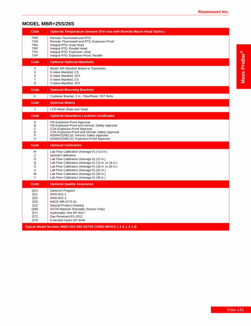
Code Optional Temperature Sensors (For Use with Remote Mount Head Styles.)
TRRTXRTRATRPTXATXP
Remote Thermowell and RTDRemote Thermowell and RTD, Explosion-ProofIntegral RTD, Axial HeadIntegral RTD, Parallel HeadIntegral RTD, Explosion, AxialIntegral RTD, Explosion-Proof, Parallel
Code Optional Optional Manifolds
35678
Model 305 Manifold Bolted to Transmitter5-Valve Manifold, CS5-Valve Manifold, SST3-Valve Manifold, CS3-Valve Manifold, SST
Code Optional Mounting Brackets
K Coplanar Bracket, 2 in., Pipe/Panel, SST Bolts
Code Optional Meters
1 LCD Meter (Rate and Total)
Code Optional Hazardous Location Certificates
ABCDFH
FM Explosion-Proof ApprovalFM Explosion-Proof and Intrinsic Safety ApprovalCSA Explosion-Proof ApprovalCSA Explosion-Proof and Intrinsic Safety ApprovalKEMA/CENELEC Intrinsic Safety ApprovalKEMA/CENELEC Explosion-Proof Approval
Code Optional Calibration
MZOQSUWY
Lab Flow Calibration (Average K) (<10 in.)Special CalibrationLab Flow Calibration (Average K) (12 in.)Lab Flow Calibration (Average K) (14 in. to 16 in.)Lab Flow Calibration (Average K) (18 in. to 20 in.)Lab Flow Calibration (Average K) (24 in.)Lab Flow Calibration (Average K) (30 in.)Lab Flow Calibration (Average K) (36 in.)
Code Optional Quality Assurance
QA1Q21Q23Q29QJ2QM2QT1QT2QT8
Dieterich ProgramANSI B31.1ANSI B31.3NACE MR-0175-91Special Product DrawingASTM Material-Traceable (Sensor Only)Hydrostatic Test EP-4017Dye Penetrant ES-1012Extended Hydro EP-4046
Typical Model Number MBR+25S 060 HATS0 C0000 MP4C0 1 3 A 1 A 1 B
MODEL MBR+25S/26S
Flow-141

Flow-1
Mass ProBar ® Mass Flowmeter
Mass
ProB
ar®
MODEL MBR+35S/36S
Model Product Description
MBR+35SMBR+36S
Mass ProBar® Flowmeter - Regular (Threaded, Pak-Lok)Mass ProBar® Flowmeter - Regular (Threaded, Pak-Lok) with Opposite Side Support
Code Line Size
080100120140160180200240300360420480600720
8 in. (200 mm)10 in. (250 mm)12 in. (300 mm)14 in. (350 mm)16 in. (400 mm)18 in. (450 mm)20 in. (500 mm)24 in. (600 mm)30 in. (750 mm)36 in. (900 mm)42 in. (1066 mm)48 in. (1210 mm)60 in. 1520 mm)72 in. (1820 mm)
Code Head Style
HADS0HADSBHADSNHAMS0HAPS0
Direct and Integral Mount Heads - Horizontal LineDirect Mount, with 5-Valve Manifold, Horizontal Line, SSTDirect Mount, with 5-Valve Manifold, B31.1, Horizontal Line, SSTDirect Mount, with 5-Valve Manifold, NACE, Horizontal Line, SSTIntegral, 3-Valve Manifold, Horizontal Line, SSTDirect Mount, No Manifold, Horizontal Line, SST
HATS0HATSBHATSDHATSN
Direct and Integral Mount Heads - Horizontal Line with RTDIntegral, 3-Valve Manifold, RTD, Horizontal Line, SSTDirect Mount, 5-Valve Manifold, RTD, B31.1, Horizontal Line, SSTDirect Mount, with 5-Valve Manifold, RTD, Horizontal Line, SSTDirect Mount, 5-Valve Manifold, RTD, NACE, Horizontal Line, SST
HVDS0HVDSBHVDSNHVMS0HVPS0
Direct and Integral Mount Heads - Vertical LineDirect Mount, with 5-Valve Manifold, Vertical Line, SSTDirect Mount, 5-Valve Manifold, B31.1, Vertical Line, SSTDirect Mount, 5-Valve Manifold, NACE, Vertical Line, SSTIntegral, 3-Valve Manifold, Vertical Line, SSTDirect Mount, No Manifold, Vertical Line, SST
HVTS0HVTSBHVTSDHVTSN
Direct and Integral Mount Heads - Vertical Line with RTDIntegral, 3-Valve Manifold, RTD, Vertical Line, SSTDirect Mount, 5-Valve Manifold, RTD, B31.1, Vertical Line, SSTDirect Mount, with 5-Valve Manifold, RTD, Vertical Line, SSTDirect Mount, 5-Valve Manifold, RTD, NACE, Vertical Line, SST
HA2S0HA2SSHP2S0HP2SS
Remote Mount - Horizontal LineAxial, Horizontal Line, ½—14 NPT, SSTAxial, Horizontal Line, ½ in. Socket Weld Ports, SSTParallel, Horizontal Line, ½—14 NPT, SSTParallel, Horizontal Line, ½ in. Socket Weld Ports, SST
HPVS0HPVSSHV2S0HV2SS
Remote Mount - Vertical LineParallel, Vertical Line, ½ in. Socket Weld Ports, SSTParallel, Vertical Line, ½—14 NPT, SSTAxial, Vertical Line, ½—14 NPT, SSTAxial, Vertical Line, ½ in. Socket Weld Ports, SST
Code Instrument Connections
C0000S0000
Eliminate Instrument Connection Options (For use with Direct and Integral Mount Head Styles)Eliminate Instrument Connection AssemblyEliminate Instrument Connection Assembly (Steam)
CA2C0CP2C0SA2C0SP2C0
Needle Valve - CSNeedle Valve, Elbow, ½—14 NPT, CSNeedle Valve, Nipple, ½—14 NPT, CSNeedle Valve, Elbow and Tee, ½—14 NPT, CSNeedle Valve, Nipple and Tee, ½—14 NPT, CS
CA2S0CA2SSCP2S0CP2SSSA2S0SP2S0SP2SS
Needle Valve, Elbow, ½—14 NPT, SSTNeedle Valve, Elbow, ½ in. Socket Weld Ports, SSTNeedle Valve, Nipple, ½—14 NPT, SSTNeedle Valve, Nipple, ½ in. Socket Weld Ports, SSTNeedle Valve, Elbow and Tee, ½—14 NPT, SSTNeedle Valve, Nipple and Tee, ½—14 NPT, SSTNeedle Valve, Nipple and Tee, ½ in. Socket Weld Ports, SST
42

Rosemount Inc.
Mas
sP
roB
ar®
Code Instrument Connections (For use with Direct and Integral Mount Head Styles) (Continued)
CB2C0CC2C0SB2C0SC2C0SV2C0
Gate Valve - CSOutside Stem and Yoke Gate Valve, Elbow, ½—14 NPT, CSOutside Stem and Yoke Gate Valve, Nipple, ½—14 NPT, CSOutside Stem and Yoke Gate Valve, Elbow and Tee, ½—14 NPT, CSOutside Stem and Yoke Gate Valve, Nipple and Tee, ½—14 NPT, CSOutside Stem and Yoke Gate Valve, Vertical Line, Nipple and Tee, ½—14 NPT, CS
CB2S0CB2SSCC2S0CC2SSSB2S0SC2S0SV2S0SV2SS
Gate Valve - SSTOutside Stem and Yoke Gate Valve, Elbow, ½—14 NPT, SSTOutside Stem and Yoke Gate Valve, Elbow, ½ in. Socket Weld Ports, SSTOutside Stem and Yoke Gate Valve, Nipple, ½—14 NPT, SSTOutside Stem and Yoke Gate Valve, Nipple, ½ in. Socket Weld Ports, SSTOutside Stem and Yoke Gate Valve, Elbow and Tee, ½—14 NPT, SSTOutside Stem and Yoke Gate Valve, Nipple and Tee, Steam, ½—14 NPT, SSTOutside Stem and Yoke Gate Valve, Vertical Line, Nipple and Tee, ½—14 NPT, SSTOutside Stem and Yoke Gate Valve, Vertical Line, Nipple and Tee, ½ in. Socket Weld Ports, SST
Code Mounting Hardware
MP6C0MP6S0MR6C0MR6S0
Pak-Lok, with Contoured Weld Fitting, 1½—11.5 NPT, CSPak-Lok, with Contoured Weld Fitting, 1½—11.5 NPT, SSTPak-Lok, No Contoured Weld Fitting, 1½—11.5 NPT, CSPak-Lok, No Contoured Weld Fitting, 1½—11.5 NPT, SST
Code DP Ranges
123
0-.5 to 0-25 in H2O (0-.12 to 0-6.22 kPa)0-2.5 to 0-250 H2O (0-.62 to 0-62.2 kPa)0-10 to 0-830 H2O (0-2.48 to 0-206 kPa)
Code Static Pressure Ranges
34CD
0–8 to 0–800 psia (0–55.1 to 0–5515 kPa)0–36.26 to 0–3626 psia (250 to 25000 kPa)0–8 to 0–800 psig (0–55.1 to 0–5515 kPa)0–36.26 to 0–3626 psig (250 to 25000 kPa)
Code Output
A 4—20 mA with Digital Signal Based on HART
Code Fill Fluid
12
SiliconeInert Fill
Code Housing Material
ABCDJKLM
Epoxy-Poly-Aluminum ½—14 NPTEpoxy-Poly-Aluminum CM 20Epoxy-Poly-Aluminum PG 13.5Epoxy-Poly-Aluminum G½316 SST ½—14 NPT316 SST CM 20316 SST PG 13.5Epoxy-Poly-Aluminum G½
Code Opposite Side Support (Required for Model 36S ONLY)
MS6C0MS6CWMS6S0MS6SW
Contoured Weld Fitting and Plug, 1½—11.5 NPT, CSContoured Weld Fitting and Plug, 1½ in. Socket Weld Ports, CSContoured Weld Fitting and Plug, 1½—11.5 NPT, SSTContoured Weld Fitting and Plug, 1½ in. Socket Weld Ports, SST
Code Optional Auxiliary Mounting (Mounting alternatives for use when Contoured Weld Fitting is Not Specified in Mounting Hardware)
MT6CMT6S
Contoured Weld Fitting, 1½—11.5 NPT, CSContoured Weld Fitting, 1½—11.5 NPT, SST
Code Optional Temperature Sensors (For Use with Remote Mount Head Styles.)
TRRTXRTRATRPTXATXP
Remote Thermowell and RTDRemote Thermowell and RTD, Explosion-ProofIntegral RTD, Axial HeadIntegral RTD, Parallel HeadIntegral RTD, Explosion, AxialIntegral RTD, Explosion-Proof, Parallel
MODEL MBR+35S/36S
Flow-143

Flow-1
Mass ProBar ® Mass Flowmeter
Mass
ProB
ar®
Code Optional Optional Manifolds
35678
Model 305 Manifold Bolted to Transmitter5-Valve Manifold, CS5-Valve Manifold, SST3-Valve Manifold, CS3-Valve Manifold, SST
Code Optional Mounting Brackets
K Coplanar Bracket, 2 in., Pipe/Panel, SST Bolts
Code Optional Meters
1 LCD Meter (Rate and Total)
Code Optional Hazardous Location Certificates
ABCDFH
FM Explosion-Proof ApprovalFM Explosion-Proof and Intrinsic Safety ApprovalCSA Explosion-Proof ApprovalCSA Explosion-Proof and Intrinsic Safety ApprovalKEMA/CENELEC Intrinsic Safety ApprovalKEMA/CENELEC Explosion-Proof Approval
Code Optional Calibration
MZOQSUWY
Lab Flow Calibration (Average K) (<10 in.)Special CalibrationLab Flow Calibration (Average K) (12 in.)Lab Flow Calibration (Average K) (14 in. to 16 in.)Lab Flow Calibration (Average K) (18 in. to 20 in.)Lab Flow Calibration (Average K) (24 in.)Lab Flow Calibration (Average K) (30 in.)Lab Flow Calibration (Average K) (36 in.)
Code Optional Quality Assurance
QA1Q21Q23Q29QJ2QM2QT1QT2QT8
Dieterich ProgramANSI B31.1ANSI B31.3NACE MR-0175-91Special Product DrawingASTM Material-Traceable (Sensor Only)Hydrostatic Test EP-4017Dye Penetrant ES-1012Extended Hydro EP-4046
Typical Model Number MBR+35S 100 HATS0 C0000 MP6C0 1 3 A 1 A B
MODEL MBR+35S/36S
44

Rosemount Inc.
Mas
sP
roB
ar®
MODEL MBR+45S/46SModel Product Descriptions
MBR+45SMBR+46S
Mass ProBar® Flowmeter - Regular (Threaded, Pak-Lok)Mass ProBar® Flowmeter - Regular (Threaded, Pak-Lok) with Opposite Side Support
Code Line Size
100120140160180200240300360420480600720
10 in. (250 mm)12 in. (300 mm)14 in. (350 mm)16 in. (400 mm)18 in. (450 mm)20 in. (500 mm)24 in. (600 mm)30 in. (750 mm)36 in. (900 mm)42 in. (1066 mm)48 in. (1210 mm)60 in. 1520 mm)72 in. (1820 mm)
Code Head Style
HADS0HADSBHADSNHAMS0HAPS0
Direct and Integral Mount Heads - Horizontal LineDirect Mount, with 5-Valve Manifold, Horizontal Line, SSTDirect Mount, with 5-Valve Manifold, B31.1, Horizontal Line, SSTDirect Mount, with 5-Valve Manifold, NACE, Horizontal Line, SSTIntegral, 3-Valve Manifold, Horizontal Line, SSTDirect Mount, No Manifold, Horizontal Line, SST
HATS0HATSBHATSDHATSN
Direct and Integral Mount Heads - Horizontal Line with RTDIntegral, 3-Valve Manifold, RTD, Horizontal Line, SSTDirect Mount, 5-Valve Manifold, RTD, B31.1, Horizontal Line, SSTDirect Mount, with 5-Valve Manifold, RTD, Horizontal Line, SSTDirect Mount, 5-Valve Manifold, RTD, NACE, Horizontal Line, SST
HVDS0HVDSNHVMS0HVPS0HVDSB
Direct and Integral Mount Heads - Vertical LineDirect Mount, with 5-Valve Manifold, Vertical Line, SSTDirect Mount, 5-Valve Manifold, NACE, Vertical Line, SSTIntegral, 3-Valve Manifold, Vertical Line, SSTDirect Mount, No Manifold, Vertical Line, SSTDirect Mount, 5-Valve Manifold, B31.1, Vertical Line, SST
HVTS0HVTSBHVTSDHVTSN
Direct and Integral Mount Heads - Vertical Line with RTDIntegral, 3-Valve Manifold, RTD, Vertical Line, SSTDirect Mount, 5-Valve Manifold, RTD, B31.1, Vertical Line, SSTDirect Mount, with 5-Valve Manifold, RTD, Vertical Line, SSTDirect Mount, 5-Valve Manifold, RTD, NACE, Vertical Line, SST
HA2S0HA2SSHP2S0HP2SS
Remote Mount - Horizontal LineAxial, Horizontal Line, ½—14 NPT, SSTAxial, Horizontal Line, ½ in. Socket Weld Ports, SSTParallel, Horizontal Line, ½—14 NPT, SSTParallel, Horizontal Line, ½ in. Socket Weld Ports, SST
HPVS0HPVSSHV2S0HV2SS
Parallel, Vertical Line, ½ in. Socket Weld Ports, SSTParallel, Vertical Line, ½—14 NPT, SSTAxial, Vertical Line, ½—14 NPT, SSTAxial, Vertical Line, ½ in. Socket Weld Ports, SST
Code Instrument Connections
C0000S0000
Eliminate Instrument Connection Options (For use with Direct and Integral Mount Head Styles)Eliminate Instrument Connection AssemblyEliminate Instrument Connection Assembly (Steam)
CP2C0SP2C0
Needle Valve - CSNeedle Valve, Nipple, ½—14 NPT, CSNeedle Valve, Nipple and Tee, ½—14 NPT, CS
CP2S0CP2SSSP2S0SP2SS
Needle Valve - SSTNeedle Valve, Nipple, ½—14 NPT, SSTNeedle Valve, Nipple, ½ in. Socket Weld Ports, SSTNeedle Valve, Nipple and Tee, ½—14 NPT, SSTNeedle Valve, Nipple and Tee, ½ in. Socket Weld Ports, SST
Flow-145
Flow-1
Mass ProBar ® Mass Flowmeter
Mass
ProB
ar®
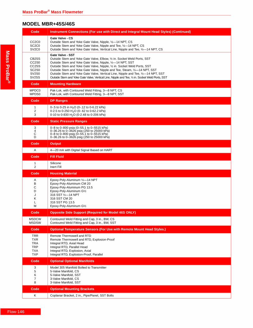
Code Instrument Connections (For use with Direct and Integral Mount Head Styles) (Continued)
CC2C0SC2C0SV2C0
Gate Valve - CSOutside Stem and Yoke Gate Valve, Nipple, ½—14 NPT, CSOutside Stem and Yoke Gate Valve, Nipple and Tee, ½—14 NPT, CSOutside Stem and Yoke Gate Valve, Vertical Line, Nipple and Tee, ½—14 NPT, CS
CB2SSCC2S0CC2SSSC2S0SV2S0SV2SS
Gate Valve - SSTOutside Stem and Yoke Gate Valve, Elbow, ½ in. Socket Weld Ports, SSTOutside Stem and Yoke Gate Valve, Nipple, ½—14 NPT, SSTOutside Stem and Yoke Gate Valve, Nipple, ½ in. Socket Weld Ports, SSTOutside Stem and Yoke Gate Valve, Nipple and Tee, Steam, ½—14 NPT, SSTOutside Stem and Yoke Gate Valve, Vertical Line, Nipple and Tee, ½—14 NPT, SSTOutside Stem and Yoke Gate Valve, Vertical Line, Nipple and Tee, ½ in. Socket Weld Ports, SST
Code Mounting Hardware
MPDC0MPDS0
Pak-Lok, with Contoured Weld Fitting, 3—8 NPT, CSPak-Lok, with Contoured Weld Fitting, 3—8 NPT, SST
Code DP Ranges
123
0-.5 to 0-25 in H2O (0-.12 to 0-6.22 kPa)0-2.5 to 0-250 H2O (0-.62 to 0-62.2 kPa)0-10 to 0-830 H2O (0-2.48 to 0-206 kPa)
Code Static Pressure Ranges
34CD
0–8 to 0–800 psia (0–55.1 to 0–5515 kPa)0–36.26 to 0–3626 psia (250 to 25000 kPa)0–8 to 0–800 psig (0–55.1 to 0–5515 kPa)0–36.26 to 0–3626 psig (250 to 25000 kPa)
Code Output
A 4—20 mA with Digital Signal Based on HART
Code Fill Fluid
12
SiliconeInert Fill
Code Housing Material
ABCDJKLM
Epoxy-Poly-Aluminum ½—14 NPTEpoxy-Poly-Aluminum CM 20Epoxy-Poly-Aluminum PG 13.5Epoxy-Poly-Aluminum G½316 SST ½—14 NPT316 SST CM 20316 SST PG 13.5Epoxy-Poly-Aluminum G½
Code Opposite Side Support (Required for Model 46S ONLY)
MSDCWMSDSW
Contoured Weld Fitting and Cap, 3 in., BW, CSContoured Weld Fitting and Cap, 3 in., BW, SST
Code Optional Temperature Sensors (For Use with Remote Mount Head Styles.)
TRRTXRTRATRPTXATXP
Remote Thermowell and RTDRemote Thermowell and RTD, Explosion-ProofIntegral RTD, Axial HeadIntegral RTD, Parallel HeadIntegral RTD, Explosion, AxialIntegral RTD, Explosion-Proof, Parallel
Code Optional Optional Manifolds
35678
Model 305 Manifold Bolted to Transmitter5-Valve Manifold, CS5-Valve Manifold, SST3-Valve Manifold, CS3-Valve Manifold, SST
Code Optional Mounting Brackets
K Coplanar Bracket, 2 in., Pipe/Panel, SST Bolts
MODEL MBR+45S/46S
46

Rosemount Inc.
Mas
sP
roB
ar®
Code Optional Meters
1 LCD Meter (Rate and Total)
Code Optional Hazardous Location Certificates
ABCDFH
FM Explosion-Proof ApprovalFM Explosion-Proof and Intrinsic Safety ApprovalCSA Explosion-Proof ApprovalCSA Explosion-Proof and Intrinsic Safety ApprovalKEMA/CENELEC Intrinsic Safety ApprovalKEMA/CENELEC Explosion-Proof Approval
Code Optional Calibration
MZOQSUWY
Lab Flow Calibration (Average K) (<10 in.)Special CalibrationLab Flow Calibration (Average K) (12 in.)Lab Flow Calibration (Average K) (14 in. to 16 in.)Lab Flow Calibration (Average K) (18 in. to 20 in.)Lab Flow Calibration (Average K) (24 in.)Lab Flow Calibration (Average K) (30 in.)Lab Flow Calibration (Average K) (36 in.)
Code Optional Quality Assurance
QA1Q21Q23Q29QJ2QM2QT1QT2QT8
Dieterich ProgramANSI B31.1ANSI B31.3NACE MR-0175-91Special Product DrawingASTM Material-Traceable (Sensor Only)Hydrostatic Test EP-4017Dye Penetrant ES-1012Extended Hydro EP-4046
Typical Model Number MBR+45S 240 HATS0 C0000 MPDC0 2 3 A 1 B H
MODEL MBR+45S/46S
Flow-147

Mass ProBar ® Mass Flowmeter
Mass
ProB
ar®
Flow-1
48
Rosemount Inc.
Mas
sP
roB
ar®
Flow-149

Mass ProBar ® Mass Flowmeter
Mass
ProB
ar®
Flow-1
50
Rosemount Inc.
Mas
sP
roB
ar®
Flow-151

Mass ProBar ® Mass Flowmeter
Mass
ProB
ar®
Flow-1
52
Rosemount Inc.
Mas
sP
roB
ar®
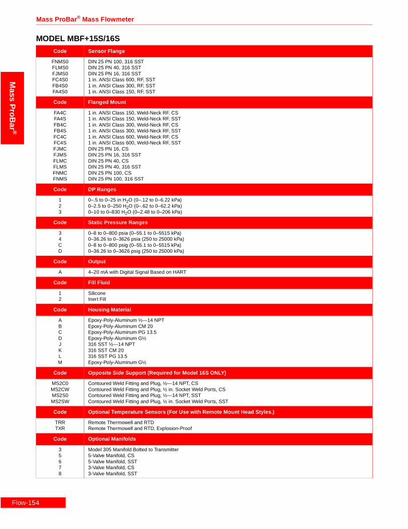
Ordering Information—Model MBFMODEL MBF+15S/16S
Code Product Description
MBF+15SMBF+16S
Mass ProBar® Flowmeter - FlangedMass ProBar® Flowmeter - Flanged with Opposite Side Support
Code Line Size
020025030035040050
2 in. (50 mm)2½ in. (63.5 mm)3 in. (80 mm)3½ in. (89 mm)4 in. (100 mm)5 in. (125 mm)
Code Head Style
HADS0HADSBHADSNHAMS0HAPS0
Direct and Integral Mount Heads - Horizontal LineDirect Mount, with 5-Valve Manifold, Horizontal Line, SSTDirect Mount, with 5-Valve Manifold, B31.1, Horizontal Line, SSTDirect Mount, with 5-Valve Manifold, NACE, Horizontal Line, SSTIntegral, 3-Valve Manifold, Horizontal Line, SSTDirect Mount, No Manifold, Horizontal Line, SST
HVDS0HVDSBHVDSNHVMS0HVPS0
Direct and Integral Mount Heads - Vertical LineDirect Mount, with 5-Valve Manifold, Vertical Line, SSTDirect Mount, 5-Valve Manifold, B31.1,Vertical Line, SSTDirect Mount, 5-Valve Manifold, NACE, Vertical Line, SSTIntegral, 3-Valve Manifold, Vertical Line, SSTDirect Mount, No Manifold, Vertical Line, SST
HA2S0HA2SSHP2S0HP2SS
Remote Mount - Horizontal LineAxial, Horizontal Line, ½—14 NPT, SSTAxial, Horizontal Line, ½ in. Socket Weld Ports, SSTParallel, Horizontal Line, ½—14 NPT, SSTParallel, Horizontal Line, ½ in. Socket Weld Ports, SST
HPVS0HPVSSHV2S0HV2SS
Remote Mount - Vertical LineParallel, Vertical Line, ½ in. Socket Weld Ports, SSTParallel, Vertical Line, ½—14 NPT, SSTAxial, Vertical Line, ½—14 NPT, SSTAxial, Vertical Line, ½ in. Socket Weld Ports, SST
Code Instrument Connections
C0000S0000
Eliminate Instrument Connection Options (For use with Direct and Integral Mount Head Styles)Eliminate Instrument Connection AssemblyEliminate Instrument Connection Assembly (Steam)
CP2C0SP2C0CA2C0SA2C0
Needle Valve - CSNeedle Valve, Nipple, ½—14 NPT, CSNeedle Valve, Nipple and Tee, ½—14 NPT, CSNeedle Valve, Elbow, ½—14 NPT, CSNeedle Valve, Elbow and Tee, ½—14 NPT, CS
CA2SSCP2S0CP2SSSP2S0SP2SSCA2S0SA2S0
Needle Valve - SSTNeedle Valve, Elbow, ½ in. Socket Weld Ports, SSTNeedle Valve, Nipple, ½—14 NPT, SSTNeedle Valve, Nipple, ½ in. Socket Weld Ports, SSTNeedle Valve, Nipple and Tee, ½—14 NPT, SSTNeedle Valve, Nipple and Tee, ½ in. Socket Weld Ports, SSTNeedle Valve, Elbow, ½—14 NPT, SSTNeedle Valve, Elbow and Tee, ½—14 NPT, SST
CC2C0SC2C0SV2C0CB2C0SB2C0
Gate Valve - CSOutside Stem and Yoke Gate Valve, Nipple, ½—14 NPT, CSOutside Stem and Yoke Gate Valve, Nipple and Tee, ½—14 NPT, CSOutside Stem and Yoke Gate Valve, Vertical Line, Nipple and Tee, ½—14 NPT, CSOutside Stem and Yoke Gate Valve, Elbow, ½—14 NPT, CSOutside Stem and Yoke Gate Valve, Elbow and Tee, ½—14 NPT, CS
CB2SSCC2S0CC2SSSC2S0SV2S0SV2SSCB2S0SB2S0
Gate Valve - SSTOutside Stem and Yoke Gate Valve, Elbow, ½ in. Socket Weld Ports, SSTOutside Stem and Yoke Gate Valve, Nipple, ½—14 NPT, SSTOutside Stem and Yoke Gate Valve, Nipple, ½ in. Socket Weld Ports, SSTOutside Stem and Yoke Gate Valve, Nipple and Tee, Steam, ½—14 NPT, SSTOutside Stem and Yoke Gate Valve, Vertical Line, Nipple and Tee, ½—14 NPT, SSTOutside Stem and Yoke Gate Valve, Vertical Line, Nipple and Tee, ½ in. Socket Weld Ports, SSTOutside Stem and Yoke Gate Valve, Elbow, ½—14 NPT, SSTOutside Stem and Yoke Gate Valve, Elbow and Tee, ½—14 NPT, SST
Flow-153
Flow-1
Mass ProBar ® Mass Flowmeter
Mass
ProB
ar®
Code Sensor Flange
FNMS0FLMS0FJMS0FC4S0FB4S0FA4S0
DIN 25 PN 100, 316 SSTDIN 25 PN 40, 316 SSTDIN 25 PN 16, 316 SST1 in. ANSI Class 600, RF, SST1 in. ANSI Class 300, RF, SST1 in. ANSI Class 150, RF, SST
Code Flanged Mount
FA4CFA4SFB4CFB4SFC4CFC4SFJMCFJMSFLMCFLMSFNMCFNMS
1 in. ANSI Class 150, Weld-Neck RF, CS1 in. ANSI Class 150, Weld-Neck RF, SST1 in. ANSI Class 300, Weld-Neck RF, CS1 in. ANSI Class 300, Weld-Neck RF, SST1 in. ANSI Class 600, Weld-Neck RF, CS1 in. ANSI Class 600, Weld-Neck RF, SSTDIN 25 PN 16, CSDIN 25 PN 16, 316 SSTDIN 25 PN 40, CSDIN 25 PN 40, 316 SSTDIN 25 PN 100, CSDIN 25 PN 100, 316 SST
Code DP Ranges
123
0–.5 to 0–25 in H2O (0–.12 to 0–6.22 kPa)0–2.5 to 0–250 H2O (0–.62 to 0–62.2 kPa)0–10 to 0–830 H2O (0–2.48 to 0–206 kPa)
Code Static Pressure Ranges
34CD
0–8 to 0–800 psia (0–55.1 to 0–5515 kPa)0–36.26 to 0–3626 psia (250 to 25000 kPa)0–8 to 0–800 psig (0–55.1 to 0–5515 kPa)0–36.26 to 0–3626 psig (250 to 25000 kPa)
Code Output
A 4–20 mA with Digital Signal Based on HART
Code Fill Fluid
12
SiliconeInert Fill
Code Housing Material
ABCDJKLM
Epoxy-Poly-Aluminum ½—14 NPTEpoxy-Poly-Aluminum CM 20Epoxy-Poly-Aluminum PG 13.5Epoxy-Poly-Aluminum G½316 SST ½—14 NPT316 SST CM 20316 SST PG 13.5Epoxy-Poly-Aluminum G½
Code Opposite Side Support (Required for Model 16S ONLY)
MS2C0MS2CWMS2S0MS2SW
Contoured Weld Fitting and Plug, ½—14 NPT, CSContoured Weld Fitting and Plug, ½ in. Socket Weld Ports, CSContoured Weld Fitting and Plug, ½—14 NPT, SSTContoured Weld Fitting and Plug, ½ in. Socket Weld Ports, SST
Code Optional Temperature Sensors (For Use with Remote Mount Head Styles.)
TRRTXR
Remote Thermowell and RTDRemote Thermowell and RTD, Explosion-Proof
Code Optional Manifolds
35678
Model 305 Manifold Bolted to Transmitter5-Valve Manifold, CS5-Valve Manifold, SST3-Valve Manifold, CS3-Valve Manifold, SST
MODEL MBF+15S/16S
54

Rosemount Inc.
Mas
sP
roB
ar®
Code Optional Optional Mounting Brackets
K Coplanar Bracket, 2 in., Pipe/Panel, SST Bolts
Code Optional Meters
1 LCD Meter (Rate and Total)
Code Optional Hazardous Location Certificates
ABCDFH
FM Explosion-Proof ApprovalFM Explosion-Proof and Intrinsic Safety ApprovalCSA Explosion-Proof ApprovalCSA Explosion-Proof and Intrinsic Safety ApprovalKEMA/CENELEC Intrinsic Safety ApprovalKEMA/CENELEC Explosion-Proof Approval
Code Optional Calibration
MZ
Lab Flow Calibration (Average K) (<10 in.)Special Calibration
Code Optional Quality Assurance
QA1Q21Q23Q29QJ2QM2QT1QT2QT8
Dieterich ProgramANSI B31.1ANSI B31.3NACE MR-0175-91Special Product DrawingASTM Material-Traceable (Sensor Only)Hydrostatic Test EP-4017Dye Penetrant ES-1012Extended Hydro EP-4046
Typical Model Number MBF+15S 020 HAMS0 CP2C0 FA4S0 FA4C 1 3 A 1 A 1 TXR B
MODEL MBF+15S/16S
Flow-155

Flow-1
Mass ProBar ® Mass Flowmeter
Mass
ProB
ar®
Model MBF+25S/26SModel Product Description
MBF+25SMBF+26S
Mass ProBar® Flowmeter - FlangedMass ProBar® Flowmeter - Flanged with Opposite Side Support
Code Line Size
040050060080100120140160180200240300360
4 in. (100 mm)5 in. (125 mm)6 in. (150 mm)8 in. (200 mm)10 in. (250 mm)12 in. (300 mm)14 in. (350 mm)16 in. (400 mm)18 in. (450 mm)20 in. (500 mm)24 in. (600 mm)30 in. (750 mm)36 in. (900 mm)
Code Head Style
HADS0HADSBHADSNHAMS0HAPS0HAXS0
Direct and Integral Mount Heads - Horizontal LineDirect Mount, with 5-Valve Manifold, Horizontal Line, SSTDirect Mount, with 5-Valve Manifold, B31.1, Horizontal Line, SSTDirect Mount, with 5-Valve Manifold, NACE, Horizontal Line, SSTIntegral, 3-Valve Manifold, Horizontal Line, SSTDirect Mount, No Manifold, Horizontal Line, SSTDirect Mount, Quantity Two, 3-Valve Manifold, Horizontal Line, SST
HATS0HATSBHATSDHATSN
Direct and Integral Mount Heads - Horizontal Line with RTDIntegral, 3-Valve Manifold, RTD, Horizontal Line, SSTDirect Mount, 5-Valve Manifold, RTD, B31.1, Horizontal Line, SSTDirect Mount, with 5-Valve Manifold, RTD, Horizontal Line, SSTDirect Mount, 5-Valve Manifold, RTD, NACE, Horizontal Line, SST
HVDS0HVDSBHVDSNHVMS0HVPS0
Direct and Integral Mount Heads - Vertical LineDirect Mount, with 5-Valve Manifold, Vertical Line, SSTDirect Mount, 5-Valve Manifold, B31.1,Vertical Line, SSTDirect Mount, 5-Valve Manifold, NACE, Vertical Line, SSTIntegral, 3-Valve Manifold, Vertical Line, SSTDirect Mount, No Manifold, Vertical Line, SST
HP2SSHA2S0HA2SSHP2S0
Remote Mount - Horizontal LineParallel, Horizontal Line, ½ in. Socket Weld Ports, SSTAxial, Horizontal Line, ½—14 NPT, SSTAxial, Horizontal Line, ½ in. Socket Weld Ports, SSTParallel, Horizontal Line, ½—14 NPT, SST
HPVS0HPVSSHV2S0HV2SS
Remote Mount - Vertical LineParallel, Vertical Line, ½ in. Socket Weld Ports, SSTParallel, Vertical Line, ½—14 NPT, SSTAxial, Vertical Line, ½—14 NPT, SSTAxial, Vertical Line, ½ in. Socket Weld Ports, SST
Code Instrument Connections
C0000S0000
Eliminate Instrument Connection Options (For use with Direct and Integral Mount Head Styles)Eliminate Instrument Connection AssemblyEliminate Instrument Connection Assembly (Steam)
CA2SSCP2S0CP2SSSP2S0SP2SSCA2S0SA2S0
Needle Valve - SSTNeedle Valve, Elbow, ½ in. Socket Weld Ports, SSTNeedle Valve, Nipple, ½—14 NPT, SSTNeedle Valve, Nipple, ½ in. Socket Weld Ports, SSTNeedle Valve, Nipple and Tee, ½—14 NPT, SSTNeedle Valve, Nipple and Tee, ½ in. Socket Weld Ports, SSTNeedle Valve, Elbow, ½—14 NPT, SSTNeedle Valve, Elbow and Tee, ½—14 NPT, SST
CC2C0SC2C0SV2C0CB2C0SB2C0
Gate Valve - CSOutside Stem and Yoke Gate Valve, Nipple, ½—14 NPT, CSOutside Stem and Yoke Gate Valve, Nipple and Tee, ½—14 NPT, CSOutside Stem and Yoke Gate Valve, Vertical Line, Nipple and Tee, ½—14 NPT, CSOutside Stem and Yoke Gate Valve, Elbow, ½—14 NPT, CSOutside Stem and Yoke Gate Valve, Elbow and Tee, ½—14 NPT, CS
56

Rosemount Inc.
Mas
sP
roB
ar®
Code Instrument Connections (For use with Direct and Integral Mount Head Styles) (Continued)
CB2SSCC2S0CC2SSSC2S0SV2S0SV2SSCB2S0SB2S0
Gate Valve - SSTOutside Stem and Yoke Gate Valve, Elbow, ½ in. Socket Weld Ports, SSTOutside Stem and Yoke Gate Valve, Nipple, ½—14 NPT, SSTOutside Stem and Yoke Gate Valve, Nipple, ½ in. Socket Weld Ports, SSTOutside Stem and Yoke Gate Valve, Nipple and Tee, Steam, ½—14 NPT, SSTOutside Stem and Yoke Gate Valve, Vertical Line, Nipple and Tee, ½—14 NPT, SSTOutside Stem and Yoke Gate Valve, Vertical Line, Nipple and Tee, ½ in. Socket Weld Ports, SSTOutside Stem and Yoke Gate Valve, Elbow, ½—14 NPT, SSTOutside Stem and Yoke Gate Valve, Elbow and Tee, ½—14 NPT, SST
Code Sensor Flange
FNPS0FLPS0FJPS0FC6S0FB6S0FA6S0
DIN 40 PN 100, 316 SSTDIN 40 PN 40, 316 SSTDIN 40 PN 16, 316 SST1½ in. ANSI Class 600, RF, SST1½ in. ANSI Class 300, RF, SST1½ in. ANSI Class 150, RF, SST
Code Flanged Mount
FA6CFA6SFB6CFB6SFC6CFC6SFJPCFJPSFLPCFLPSFNPCFNPS
1½ in. ANSI Class 150, Weld-Neck RF, CS1½ in. ANSI Class 150, Weld-Neck RF, SST1½ in. ANSI Class 300, Weld-Neck RF, CS1½ in. ANSI Class 300, Weld-Neck RF, SST1½ in. ANSI Class 600, Weld-Neck RF, CS1½ in. ANSI Class 600, Weld-Neck RF, SSTDIN 40 PN 16, CSDIN 40 PN 16, 316 SSTDIN 40 PN 40, CSDIN 40 PN 40, 316 SSTDIN 40 PN 100, CSDIN 40 PN 100, 316 SST
Code DP Ranges
123
0–.5 to 0–25 in H2O (0–.12 to 0–6.22 kPa)0–2.5 to 0–250 H2O (0–.62 to 0–62.2 kPa)0–10 to 0–830 H2O (0–2.48 to 0–206 kPa)
Code Static Pressure Ranges
34CD
0–8 to 0–800 psia (0–55.1 to 0–5515 kPa)0–36.26 to 0–3626 psia (250 to 25000 kPa)0–8 to 0–800 psig (0–55.1 to 0–5515 kPa)0–36.26 to 0–3626 psig (250 to 25000 kPa)
Code Output
A 4–20 mA with Digital Signal Based on HART
Code Fill Fluid
12
SiliconeInert Fill
Code Housing Material
ABCDJKLM
Epoxy-Poly-Aluminum ½—14 NPTEpoxy-Poly-Aluminum CM 20Epoxy-Poly-Aluminum PG 13.5Epoxy-Poly-Aluminum G½316 SST ½—14 NPT316 SST CM 20316 SST PG 13.5Epoxy-Poly-Aluminum G½
Code Opposite Side Support (Required for Model 26S ONLY)
MS4C0MS4CWMS4S0MS4SW
Contoured Weld Fitting and Plug, 1—11.5 NPT, CSContoured Weld Fitting and Plug, 1 in. Socket Weld Ports, CSContoured Weld Fitting and Plug, 1—11.5 NPT, SSTContoured Weld Fitting and Plug, 1 in. Socket Weld Ports, SST
Model MBF+25S/26S
Flow-157
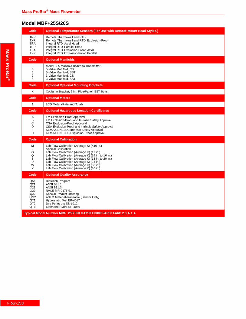
Flow-1
Mass ProBar ® Mass Flowmeter
Mass
ProB
ar®
Code Optional Temperature Sensors (For Use with Remote Mount Head Styles.)
TRRTXRTRATRPTXATXP
Remote Thermowell and RTDRemote Thermowell and RTD, Explosion-ProofIntegral RTD, Axial HeadIntegral RTD, Parallel HeadIntegral RTD, Explosion-Proof, AxialIntegral RTD, Explosion-Proof, Parallel
Code Optional Manifolds
35678
Model 305 Manifold Bolted to Transmitter5-Valve Manifold, CS5-Valve Manifold, SST3-Valve Manifold, CS3-Valve Manifold, SST
Code Optional Optional Mounting Brackets
K Coplanar Bracket, 2 in., Pipe/Panel, SST Bolts
Code Optional Meters
1 LCD Meter (Rate and Total)
Code Optional Hazardous Location Certificates
ABCDFH
FM Explosion-Proof ApprovalFM Explosion-Proof and Intrinsic Safety ApprovalCSA Explosion-Proof ApprovalCSA Explosion-Proof and Intrinsic Safety ApprovalKEMA/CENELEC Intrinsic Safety ApprovalKEMA/CENELEC Explosion-Proof Approval
Code Optional Calibration
MZOQSUWY
Lab Flow Calibration (Average K) (<10 in.)Special CalibrationLab Flow Calibration (Average K) (12 in.)Lab Flow Calibration (Average K) (14 in. to 16 in.)Lab Flow Calibration (Average K) (18 in. to 20 in.)Lab Flow Calibration (Average K) (24 in.)Lab Flow Calibration (Average K) (30 in.)Lab Flow Calibration (Average K) (36 in.)
Code Optional Quality Assurance
QA1Q21Q23Q29QJ2QM2QT1QT2QT8
Dieterich ProgramANSI B31.1ANSI B31.3NACE MR-0175-91Special Product DrawingASTM Material-Traceable (Sensor Only)Hydrostatic Test EP-4017Dye Penetrant ES-1012Extended Hydro EP-4046
Typical Model Number MBF+25S 060 HATS0 C0000 FA6S0 FA6C 2 3 A 1 A
Model MBF+25S/26S
58
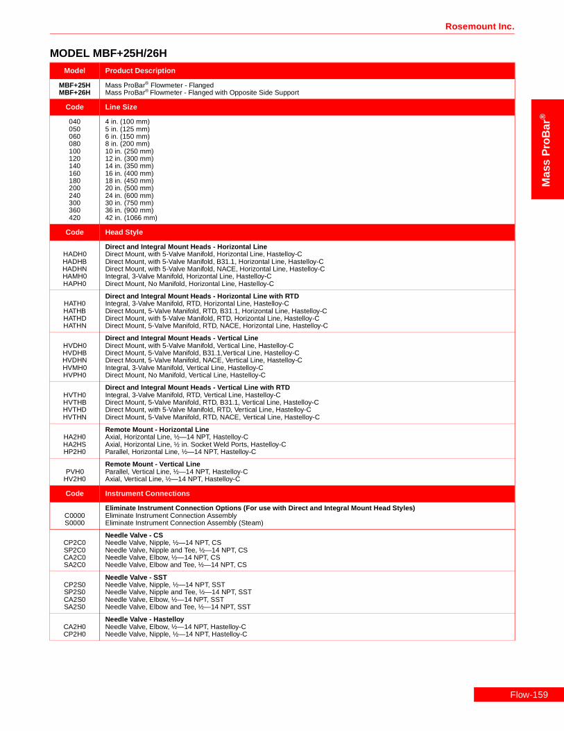
Rosemount Inc.
Mas
sP
roB
ar®
MODEL MBF+25H/26HModel Product Description
MBF+25HMBF+26H
Mass ProBar® Flowmeter - FlangedMass ProBar® Flowmeter - Flanged with Opposite Side Support
Code Line Size
040050060080100120140160180200240300360420
4 in. (100 mm)5 in. (125 mm)6 in. (150 mm)8 in. (200 mm)10 in. (250 mm)12 in. (300 mm)14 in. (350 mm)16 in. (400 mm)18 in. (450 mm)20 in. (500 mm)24 in. (600 mm)30 in. (750 mm)36 in. (900 mm)42 in. (1066 mm)
Code Head Style
HADH0HADHBHADHNHAMH0HAPH0
Direct and Integral Mount Heads - Horizontal LineDirect Mount, with 5-Valve Manifold, Horizontal Line, Hastelloy-CDirect Mount, with 5-Valve Manifold, B31.1, Horizontal Line, Hastelloy-CDirect Mount, with 5-Valve Manifold, NACE, Horizontal Line, Hastelloy-CIntegral, 3-Valve Manifold, Horizontal Line, Hastelloy-CDirect Mount, No Manifold, Horizontal Line, Hastelloy-C
HATH0HATHBHATHDHATHN
Direct and Integral Mount Heads - Horizontal Line with RTDIntegral, 3-Valve Manifold, RTD, Horizontal Line, Hastelloy-CDirect Mount, 5-Valve Manifold, RTD, B31.1, Horizontal Line, Hastelloy-CDirect Mount, with 5-Valve Manifold, RTD, Horizontal Line, Hastelloy-CDirect Mount, 5-Valve Manifold, RTD, NACE, Horizontal Line, Hastelloy-C
HVDH0HVDHBHVDHNHVMH0HVPH0
Direct and Integral Mount Heads - Vertical LineDirect Mount, with 5-Valve Manifold, Vertical Line, Hastelloy-CDirect Mount, 5-Valve Manifold, B31.1,Vertical Line, Hastelloy-CDirect Mount, 5-Valve Manifold, NACE, Vertical Line, Hastelloy-CIntegral, 3-Valve Manifold, Vertical Line, Hastelloy-CDirect Mount, No Manifold, Vertical Line, Hastelloy-C
HVTH0HVTHBHVTHDHVTHN
Direct and Integral Mount Heads - Vertical Line with RTDIntegral, 3-Valve Manifold, RTD, Vertical Line, Hastelloy-CDirect Mount, 5-Valve Manifold, RTD, B31.1, Vertical Line, Hastelloy-CDirect Mount, with 5-Valve Manifold, RTD, Vertical Line, Hastelloy-CDirect Mount, 5-Valve Manifold, RTD, NACE, Vertical Line, Hastelloy-C
HA2H0HA2HSHP2H0
Remote Mount - Horizontal LineAxial, Horizontal Line, ½—14 NPT, Hastelloy-CAxial, Horizontal Line, ½ in. Socket Weld Ports, Hastelloy-CParallel, Horizontal Line, ½—14 NPT, Hastelloy-C
PVH0HV2H0
Remote Mount - Vertical LineParallel, Vertical Line, ½—14 NPT, Hastelloy-CAxial, Vertical Line, ½—14 NPT, Hastelloy-C
Code Instrument Connections
C0000S0000
Eliminate Instrument Connection Options (For use with Direct and Integral Mount Head Styles)Eliminate Instrument Connection AssemblyEliminate Instrument Connection Assembly (Steam)
CP2C0SP2C0CA2C0SA2C0
Needle Valve - CSNeedle Valve, Nipple, ½—14 NPT, CSNeedle Valve, Nipple and Tee, ½—14 NPT, CSNeedle Valve, Elbow, ½—14 NPT, CSNeedle Valve, Elbow and Tee, ½—14 NPT, CS
CP2S0SP2S0CA2S0SA2S0
Needle Valve - SSTNeedle Valve, Nipple, ½—14 NPT, SSTNeedle Valve, Nipple and Tee, ½—14 NPT, SSTNeedle Valve, Elbow, ½—14 NPT, SSTNeedle Valve, Elbow and Tee, ½—14 NPT, SST
CA2H0CP2H0
Needle Valve - HastelloyNeedle Valve, Elbow, ½—14 NPT, Hastelloy-CNeedle Valve, Nipple, ½—14 NPT, Hastelloy-C
Flow-159

Flow-1
Mass ProBar ® Mass Flowmeter
Mass
ProB
ar®
Code Instrument Connections (For use with Direct and Integral Mount Head Styles) (Continued)
CC2C0SC2C0SV2C0CB2C0SB2C0
Gate Valve - CSOutside Stem and Yoke Gate Valve, Nipple, ½—14 NPT, CSOutside Stem and Yoke Gate Valve, Nipple and Tee, ½—14 NPT, CSOutside Stem and Yoke Gate Valve, Vertical Line, Nipple and Tee, ½—14 NPT, CSOutside Stem and Yoke Gate Valve, Elbow, ½—14 NPT, CSOutside Stem and Yoke Gate Valve, Elbow and Tee, ½—14 NPT, CS
CC2S0SC2S0SV2S0CB2S0SB2S0
Gate Valve - SSTOutside Stem and Yoke Gate Valve, Nipple, ½—14 NPT, SSTOutside Stem and Yoke Gate Valve, Nipple and Tee, Steam, ½—14 NPT, SSTOutside Stem and Yoke Gate Valve, Vertical Line, Nipple and Tee, ½—14 NPT, SSTOutside Stem and Yoke Gate Valve, Elbow, ½—14 NPT, SSTOutside Stem and Yoke Gate Valve, Elbow and Tee, ½—14 NPT, SST
Code Sensor Flange
FC6H0FB6H0FA6H0
1½ in. ANSI Class 600, RF, Hastelloy-C1½ in. ANSI Class 300, RF, Hastelloy-C1½ in. ANSI Class 150, RF, Hastelloy-C
Code Flanged Mount
FA6CFA6SFB6CFB6SFC6CFC6S
1½ in. ANSI Class 150, Weld-Neck RF, CS1½ in. ANSI Class 150, Weld-Neck RF, SST1½ in. ANSI Class 300, Weld-Neck RF, CS1½ in. ANSI Class 300, Weld-Neck RF, SST1½ in. ANSI Class 600, Weld-Neck RF, CS1½ in. ANSI Class 600, Weld-Neck RF, SST
Code DP Ranges
23
0–2.5 to 0–250 H2O (0–.62 to 0–62.2 kPa)0–10 to 0–830 H2O (0-–2.48 to 0–206 kPa)
Code Static Pressure Ranges
34CD
0–8 to 0–800 psia (0–55.1 to 0–5515 kPa)0–36.26 to 0–3626 psia (250 to 25000 kPa)0–8 to 0–800 psig (0–55.1 to 0–5515 kPa)0–36.26 to 0–3626 psig (250 to 25000 kPa)
Code Output
A 4–20 mA with Digital Signal Based on HART
Code Fill Fluid
12
SiliconeInert Fill
Code Housing Material
ABCDJKLM
Epoxy-Poly-Aluminum ½—14 NPTEpoxy-Poly-Aluminum CM 20Epoxy-Poly-Aluminum PG 13.5Epoxy-Poly-Aluminum G½316 SST ½—14 NPT316 SST CM 20316 SST PG 13.5Epoxy-Poly-Aluminum G½
Code Opposite Side Support (Required for Model 26H ONLY)
MS4C0MS4CWMS4S0MS4SW
Contoured Weld Fitting and Plug, 1—11.5 NPT, CSContoured Weld Fitting and Plug, 1 in. Socket Weld Ports, CSContoured Weld Fitting and Plug, 1—11.5 NPT, SSTContoured Weld Fitting and Plug, 1 in. Socket Weld Ports, SST
Code Optional Temperature Sensors (For Use with Remote Mount Head Styles.)
TRRTXRTRATRPTXATXP
Remote Thermowell and RTDRemote Thermowell and RTD, Explosion-ProofIntegral RTD, Axial HeadIntegral RTD, Parallel HeadIntegral RTD, Explosion-Proof, AxialIntegral RTD, Explosion-Proof, Parallel
MODEL MBF+25H/26H
60

Rosemount Inc.
Mas
sP
roB
ar®
Code Optional Manifolds
35678
Model 305 Manifold Bolted to Transmitter5-Valve Manifold, CS5-Valve Manifold, SST3-Valve Manifold, CS3-Valve Manifold, SST
Code Optional Optional Mounting Brackets
K Coplanar Bracket, 2 in., Pipe/Panel, SST Bolts
Code Optional Meters
1 LCD Meter (Rate and Total)
Code Optional Hazardous Location Certificates
ABCDFH
FM Explosion-Proof ApprovalFM Explosion-Proof and Intrinsic Safety ApprovalCSA Explosion-Proof ApprovalCSA Explosion-Proof and Intrinsic Safety ApprovalKEMA/CENELEC Intrinsic Safety ApprovalKEMA/CENELEC Explosion-Proof Approval
Code Optional Calibration
MZOQSUWY
Lab Flow Calibration (Average K) (<10 in.)Special CalibrationLab Flow Calibration (Average K) (12 in.)Lab Flow Calibration (Average K) (14 in. to 16 in.)Lab Flow Calibration (Average K) (18 in. to 20 in.)Lab Flow Calibration (Average K) (24 in.)Lab Flow Calibration (Average K) (30 in.)Lab Flow Calibration (Average K) (36 in.)
Code Optional Quality Assurance
QA1Q21Q23Q29QJ2QM2QT1QT2QT8
Dieterich ProgramANSI B31.1ANSI B31.3NACE MR-0175-91Special Product DrawingASTM Material-Traceable (Sensor Only)Hydrostatic Test EP-4017Dye Penetrant ES-1012Extended Hydro EP-4046
Typical Model Number MBF+25H 060 HATH0 C0000 FA6H0 FA6C 2 3 A 1 A
MODEL MBF+25H/26H
Flow-161

Flow-1
Mass ProBar ® Mass Flowmeter
Mass
ProB
ar®
MODEL MBF+25M/26MModel Product Description
MBF+25MMBF+26M
Mass ProBar® Flowmeter - FlangedMass ProBar® Flowmeter - Flanged with Opposite Side Support
Code Line Size
040050060080100120140160180200240300360420
4 in. (100 mm)5 in. (125 mm)6 in. (150 mm)8 in. (200 mm)10 in. (250 mm)12 in. (300 mm)14 in. (350 mm)16 in. (400 mm)18 in. (450 mm)20 in. (500 mm)24 in. (600 mm)30 in. (750 mm)36 in. (900 mm)42 in. (1066 mm)
Code Head Style
HADM0HADMBHADMNHAMM0HAPM0
Direct and Integral Mount Heads - Horizontal LineDirect Mount, with 5-Valve Manifold, Horizontal Line, MonelDirect Mount, with 5-Valve Manifold, B31.1, Horizontal Line, MonelDirect Mount, with 5-Valve Manifold, NACE, Horizontal Line, MonelIntegral, 3-Valve Manifold, Horizontal Line, MonelDirect Mount, No Manifold, Horizontal Line, Monel
HATM0HATMBHATMDHATMN
Direct and Integral Mount Heads - Horizontal Line with RTDIntegral, 3-Valve Manifold, RTD, Horizontal Line, MonelDirect Mount, 5-Valve Manifold, RTD, B31.1, Horizontal Line, MonelDirect Mount, with 5-Valve Manifold, RTD, Horizontal Line, MonelDirect Mount, 5-Valve Manifold, RTD, NACE, Horizontal Line, Monel
HVDM0HVDMBHVDMNHVMM0HVPM0
Direct and Integral Mount Heads - Vertical LineDirect Mount, with 5-Valve Manifold, Vertical Line, MonelDirect Mount, 5-Valve Manifold, B31.1, Vertical Line, MonelDirect Mount, 5-Valve Manifold, NACE, Vertical Line, MonelIntegral, 3-Valve Manifold, Vertical Line, MonelDirect Mount, No Manifold, Vertical Line, Monel
HVTM0HVTMBHVTMDHVTMN
Direct and Integral Mount Heads - Vertical Line with RTDIntegral, 3-Valve Manifold, RTD, Vertical Line, MonelDirect Mount, 5-Valve Manifold, RTD, B31.1, Vertical Line, MonelDirect Mount, with 5-Valve Manifold, RTD, Vertical Line, MonelDirect Mount, 5-Valve Manifold, RTD, NACE, Vertical Line, Monel
HA2M0HA2MSHP2M0
Remote Mount - Horizontal LineAxial, Horizontal Line, ½—14 NPT, MonelAxial, Horizontal Line, ½ in. Socket Weld Ports, MonelParallel, Horizontal Line, ½—14 NPT, Monel
HPVM0HV2M0HV2MS
Remote Mount - Vertical LineParallel, Vertical Line, ½—14 NPT, MonelAxial, Vertical Line, ½—14 NPT, MonelAxial, Vertical Line, ½ in. Socket Weld Ports, Monel
Code Instrument Connections
C0000S0000
Eliminate Instrument Connection Options (For use with Direct and Integral Mount Head Styles)Eliminate Instrument Connection AssemblyEliminate Instrument Connection Assembly (Steam)
CP2C0SP2C0CA2C0SA2C0
Needle Valve - CSNeedle Valve, Nipple, ½—14 NPT, CSNeedle Valve, Nipple and Tee, ½—14 NPT, CSNeedle Valve, Elbow, ½—14 NPT, CSNeedle Valve, Elbow and Tee, ½—14 NPT, CS
CP2S0SP2S0CA2S0SA2S0
Needle Valve - SSTNeedle Valve, Nipple, ½—14 NPT, SSTNeedle Valve, Nipple and Tee, ½—14 NPT, SSTNeedle Valve, Elbow, ½—14 NPT, SSTNeedle Valve, Elbow and Tee, ½—14 NPT, SST
CP2M0CA2M0
Needle Valve - MonelNeedle Valve, Nipple, ½—14 NPT, MonelNeedle Valve, Elbow, ½—14 NPT, Monel
62

Rosemount Inc.
Mas
sP
roB
ar®
Code Instrument Connections (For use with Direct and Integral Mount Head Styles) (Continued)
CC2C0SC2C0SV2C0CB2C0SB2C0
Gate Valve - CSOutside Stem and Yoke Gate Valve, Nipple, ½—14 NPT, CSOutside Stem and Yoke Gate Valve, Nipple and Tee, ½—14 NPT, CSOutside Stem and Yoke Gate Valve, Vertical Line, Nipple and Tee, ½—14 NPT, CSOutside Stem and Yoke Gate Valve, Elbow, ½—14 NPT, CSOutside Stem and Yoke Gate Valve, Elbow and Tee, ½—14 NPT, CS
CC2S0SC2S0SV2S0CB2S0SB2S0
Gate Valve - SSTOutside Stem and Yoke Gate Valve, Nipple, ½—14 NPT, SSTOutside Stem and Yoke Gate Valve, Nipple and Tee, Steam, ½—14 NPT, SSTOutside Stem and Yoke Gate Valve, Vertical Line, Nipple and Tee, ½—14 NPT, SSTOutside Stem and Yoke Gate Valve, Elbow, ½—14 NPT, SSTOutside Stem and Yoke Gate Valve, Elbow and Tee, ½—14 NPT, SST
Code Sensor Flange
FC6M0FB6M0FA6M0
1½ in. ANSI Class 600, RF, Monel1½ in. ANSI Class 300, RF, Monel1½ in. ANSI Class 150, RF, Monel
Code Flanged Mount
FA6CFA6SFB6CFB6SFC6CFC6S
1½ in. ANSI Class 150, Weld-Neck RF, CS1½ in. ANSI Class 150, Weld-Neck RF, SST1½ in. ANSI Class 300, Weld-Neck RF, CS1½ in. ANSI Class 300, Weld-Neck RF, SST1½ in. ANSI Class 600, Weld-Neck RF, CS1½ in. ANSI Class 600, Weld-Neck RF, SST
Code DP Ranges
23
0–2.5 to 0–250 H2O (0–.62 to 0–62.2 kPa)0–10 to 0–830 H2O (0–2.48 to 0–206 kPa)
Code Static Pressure Ranges
34CD
0–8 to 0–800 psia (0–55.1 to 0–5515 kPa)0–36.26 to 0–3626 psia (250 to 25000 kPa)0–8 to 0–800 psig (0–55.1 to 0–5515 kPa)0–36.26 to 0–3626 psig (250 to 25000 kPa)
Code Output
A 4–20 mA with Digital Signal Based on HART
Code Fill Fluid
12
SiliconeInert Fill
Code Housing Material
ABCDJKLM
Epoxy-Poly-Aluminum ½—14 NPTEpoxy-Poly-Aluminum CM 20Epoxy-Poly-Aluminum PG 13.5Epoxy-Poly-Aluminum G½316 SST ½—14 NPT316 SST CM 20316 SST PG 13.5Epoxy-Poly-Aluminum G½
Code Opposite Side Support (Required for Model 26M ONLY)
MS4C0MS4CWMS4S0MS4SW
Contoured Weld Fitting and Plug, 1—11.5 NPT, CSContoured Weld Fitting and Plug, 1 in. Socket Weld Ports, CSContoured Weld Fitting and Plug, 1—11.5 NPT, SSTContoured Weld Fitting and Plug, 1 in. Socket Weld Ports, SST
Code Optional Temperature Sensors (For Use with Remote Mount Head Styles.)
TRRTXRTRATRPTXATXP
Remote Thermowell and RTDRemote Thermowell and RTD, Explosion-ProofIntegral RTD, Axial HeadIntegral RTD, Parallel HeadIntegral RTD, Explosion-Proof, AxialIntegral RTD, Explosion-Proof, Parallel
MODEL MBF+25M/26M
Flow-163

Flow-1
Mass ProBar ® Mass Flowmeter
Mass
ProB
ar®
Code Optional Manifolds
35678
Model 305 Manifold Bolted to Transmitter5-Valve Manifold, CS5-Valve Manifold, SST3-Valve Manifold, CS3-Valve Manifold, SST
Code Optional Optional Mounting Brackets
K Coplanar Bracket, 2 in., Pipe/Panel, SST Bolts
Code Optional Meters
1 LCD Meter (Rate and Total)
Code Optional Hazardous Location Certificates
ABCDFH
FM Explosion-Proof ApprovalFM Explosion-Proof and Intrinsic Safety ApprovalCSA Explosion-Proof ApprovalCSA Explosion-Proof and Intrinsic Safety ApprovalKEMA/CENELEC Intrinsic Safety ApprovalKEMA/CENELEC Explosion-Proof Approval
Code Optional Calibration
MZOQSUWY
Lab Flow Calibration (Average K) (<10 in.)Special CalibrationLab Flow Calibration (Average K) (12 in.)Lab Flow Calibration (Average K) (14 in. to 16 in.)Lab Flow Calibration (Average K) (18 in. to 20 in.)Lab Flow Calibration (Average K) (24 in.)Lab Flow Calibration (Average K) (30 in.)Lab Flow Calibration (Average K) (36 in.)
Code Optional Quality Assurance
QA1Q21Q23Q29QJ2QM2QT1QT2QT8
Dieterich ProgramANSI B31.1ANSI B31.3NACE MR-0175-91Special Product DrawingASTM Material-Traceable (Sensor Only)Hydrostatic Test EP-4017Dye Penetrant ES-1012Extended Hydro EP-4046
Typical Model Number MBF+25M 060 HATM0 C0000 FA6M0 FA6C 2 3 A 1 B F
MODEL MBF+25M/26M
64

Rosemount Inc.
Mas
sP
roB
ar®
MODEL MBF+35S/36SModel Product Description
MBF+35SMBF+36S
Mass ProBar® Flowmeter - FlangedMass ProBar® Flowmeter - Flanged with Opposite Side Support
Code Line Size
100120140160180200240300360420080480600720
10 in. (250 mm)12 in. (300 mm)14 in. (350 mm)16 in. (400 mm)18 in. (450 mm)20 in. (500 mm)24 in. (600 mm)30 in. (750 mm)36 in. (900 mm)42 in. (1066 mm)8 in. (200 mm)48 in. (1210 mm)60 in. 1520 mm)72 in. (1820 mm)
Code Head Style
HADS0HADSBHADSNHAMS0HAPS0HAXS0
Direct and Integral Mount Heads - Horizontal LineDirect Mount, with 5-Valve Manifold, Horizontal Line, SSTDirect Mount, with 5-Valve Manifold, B31.1, Horizontal Line, SSTDirect Mount, with 5-Valve Manifold, NACE, Horizontal Line, SSTIntegral, 3-Valve Manifold, Horizontal Line, SSTDirect Mount, No Manifold, Horizontal Line, SSTDirect Mount, Quantity Two, 3-Valve Manifold, Horizontal Line, SST
HATS0HATSBHATSDHATSN
Direct and Integral Mount Heads - Horizontal Line with RTDIntegral, 3-Valve Manifold, RTD, Horizontal Line, SSTDirect Mount, 5-Valve Manifold, RTD, B31.1, Horizontal Line, SSTDirect Mount, with 5-Valve Manifold, RTD, Horizontal Line, SSTDirect Mount, 5-Valve Manifold, RTD, NACE, Horizontal Line, SST
HVDS0HVDSBHVDSNHVMS0HVPS0
Direct and Integral Mount Heads - Vertical LineDirect Mount, with 5-Valve Manifold, Vertical Line, SSTDirect Mount, 5-Valve Manifold, B31.1,Vertical Line, SSTDirect Mount, 5-Valve Manifold, NACE, Vertical Line, SSTIntegral, 3-Valve Manifold, Vertical Line, SSTDirect Mount, No Manifold, Vertical Line, SST
HVTS0HVTSBHVTSDHVTSN
Direct and Integral Mount Heads - Vertical Line with RTDIntegral, 3-Valve Manifold, RTD, Vertical Line, SSTDirect Mount, 5-Valve Manifold, RTD, B31.1, Vertical Line, SSTDirect Mount, with 5-Valve Manifold, RTD, Vertical Line, SSTDirect Mount, 5-Valve Manifold, RTD, NACE, Vertical Line, SST
HP2SSHA2S0HA2SSHP2S0
Remote Mount - Horizontal LineParallel, Horizontal Line, ½ in. Socket Weld Ports, SSTAxial, Horizontal Line, ½—14 NPT, SSTAxial, Horizontal Line, ½ in. Socket Weld Ports, SSTParallel, Horizontal Line, ½—14 NPT, SST
HPVS0HPVSSHV2S0HV2SS
Remote Mount - Vertical LineParallel, Vertical Line, ½ in. Socket Weld Ports, SSTParallel, Vertical Line, ½—14 NPT, SSTAxial, Vertical Line, ½—14 NPT, SSTAxial, Vertical Line, ½ in. Socket Weld Ports, SST
Code Instrument Connections
C0000S0000
Eliminate Instrument Connection Options (For use with Direct and Integral Mount Head Styles)Eliminate Instrument Connection AssemblyEliminate Instrument Connection Assembly (Steam)
CP2C0SP2C0CA2C0SA2C0
Needle Valve - CSNeedle Valve, Nipple, ½—14 NPT, CSNeedle Valve, Nipple and Tee, ½—14 NPT, CSNeedle Valve, Elbow, ½—14 NPT, CSNeedle Valve, Elbow and Tee, ½—14 NPT, CS
CA2SSCP2S0CP2SSSP2S0SP2SSCA2S0SA2S0
Needle Valve - SSTNeedle Valve, Elbow, ½ in. Socket Weld Ports, SSTNeedle Valve, Nipple, ½—14 NPT, SSTNeedle Valve, Nipple, ½ in. Socket Weld Ports, SSTNeedle Valve, Nipple and Tee, ½—14 NPT, SSTNeedle Valve, Nipple and Tee, ½ in. Socket Weld Ports, SSTNeedle Valve, Elbow, ½—14 NPT, SSTNeedle Valve, Elbow and Tee, ½—14 NPT, SST
Flow-165

Flow-1
Mass ProBar ® Mass Flowmeter
Mass
ProB
ar®
Code Instrument Connections (For use with Direct and Integral Mount Head Styles) (Continued)
CC2C0SC2C0SV2C0CB2C0SB2C0
Gate Valve - CSOutside Stem and Yoke Gate Valve, Nipple, ½—14 NPT, CSOutside Stem and Yoke Gate Valve, Nipple and Tee, ½—14 NPT, CSOutside Stem and Yoke Gate Valve, Vertical Line, Nipple and Tee, ½—14 NPT, CSOutside Stem and Yoke Gate Valve, Elbow, ½—14 NPT, CSOutside Stem and Yoke Gate Valve, Elbow and Tee, ½—14 NPT, CS
CB2SSCC2S0CC2SSSC2S0SV2S0SV2SSCB2S0SB2S0
Gate Valve - SSTOutside Stem and Yoke Gate Valve, Elbow, ½ in. Socket Weld Ports, SSTOutside Stem and Yoke Gate Valve, Nipple, ½—14 NPT, SSTOutside Stem and Yoke Gate Valve, Nipple, ½ in. Socket Weld Ports, SSTOutside Stem and Yoke Gate Valve, Nipple and Tee, Steam, ½—14 NPT, SSTOutside Stem and Yoke Gate Valve, Vertical Line, Nipple and Tee, ½—14 NPT, SSTOutside Stem and Yoke Gate Valve, Vertical Line, Nipple and Tee, ½ in. Socket Weld Ports, SSTOutside Stem and Yoke Gate Valve, Elbow, ½—14 NPT, SSTOutside Stem and Yoke Gate Valve, Elbow and Tee, ½—14 NPT, SST
Code Sensor Flanges
FNRS0FLRS0FJRS0FC8S0FB8S0FA8S0
DIN 50 PN 100, 316 SSTDIN 50 PN 40, 316 SSTDIN 50 PN 16, 316 SST2 in. ANSI Class 600, RF, SST2 in. ANSI Class 300, RF, SST2 in. ANSI Class 150, RF, SST
Code Flanged Mount
FA8CFA8SFB8CFB8SFC8CFC8SFJRCFJRSFLTCFLTSFNTCFNTS
2 in. ANSI Class 150, Weld-Neck RF, CS2 in. ANSI Class 150, Weld-Neck RF, SST2 in. ANSI Class 300, Weld-Neck RF, CS2 in. ANSI Class 300, Weld-Neck RF, SST2 in. ANSI Class 600, Weld-Neck RF, CS2 in. ANSI Class 600, Weld-Neck RF, SSTDIN 50 PN 16, CSDIN 50 PN 16, 316 SSTDIN 50 PN 40, CSDIN 50 PN 40, 316 SSTDIN 50 PN 100, CSDIN 50 PN 100, 316 SST
Code DP Ranges
123
0–.5 to 0–25 in H2O (0–.12 to 0–6.22 kPa)0–2.5 to 0–250 H2O (0–.62 to 0–62.2 kPa)0–10 to 0–830 H2O (0–2.48 to 0–206 kPa)
Code Static Pressure Ranges
34CD
0–8 to 0–800 psia (0–55.1 to 0–5515 kPa)0–36.26 to 0–3626 psia (250 to 25000 kPa)0–8 to 0–800 psig (0–55.1 to 0–5515 kPa)0–36.26 to 0–3626 psig (250 to 25000 kPa)
Code Output
A 4–20 mA with Digital Signal Based on HART
Code Fill Fluid
12
SiliconeInert Fill
Code Housing Material
ABCDJKLM
Epoxy-Poly-Aluminum ½—14 NPTEpoxy-Poly-Aluminum CM 20Epoxy-Poly-Aluminum PG 13.5Epoxy-Poly-Aluminum G½316 SST ½—14 NPT316 SST CM 20316 SST PG 13.5Epoxy-Poly-Aluminum G½
MODEL MBF+35S/36S
66

Rosemount Inc.
Mas
sP
roB
ar®
Code Opposite Side Support (Required for Model 36S ONLY)
MS6C0MS6CWMS6S0MS6SW
Contoured Weld Fitting and Plug, 1½—11.5 NPT, CSContoured Weld Fitting and Plug, 1½ in. Socket Weld Ports, CSContoured Weld Fitting and Plug, 1½—11.5 NPT, SSTContoured Weld Fitting and Plug, 1½ in. Socket Weld Ports, SST
Code Optional Temperature Sensors (For Use with Remote Mount Head Styles.)
TRRTXRTRATRPTXATXP
Remote Thermowell and RTDRemote Thermowell and RTD, Explosion-ProofIntegral RTD, Axial HeadIntegral RTD, Parallel HeadIntegral RTD, Explosion-Proof, AxialIntegral RTD, Explosion-Proof, Parallel
Code Optional Manifolds
35678
Model 305 Manifold Bolted to Transmitter5-Valve Manifold, CS5-Valve Manifold, SST3-Valve Manifold, CS3-Valve Manifold, SST
Code Optional Mounting Brackets
K Coplanar Bracket, 2 in., Pipe/Panel, SST Bolts
Code Optional Optional Meters
1 LCD Meter (Rate and Total)
Code Optional Hazardous Location Certificates
ABCDFH
FM Explosion-Proof ApprovalFM Explosion-Proof and Intrinsic Safety ApprovalCSA Explosion-Proof ApprovalCSA Explosion-Proof and Intrinsic Safety ApprovalKEMA/CENELEC Intrinsic Safety ApprovalKEMA/CENELEC Explosion-Proof Approval
Code Optional Calibration
MZOQSUWY
Lab Flow Calibration (Average K) (<10 in.)Special CalibrationLab Flow Calibration (Average K) (12 in.)Lab Flow Calibration (Average K) (14 in. to 16 in.)Lab Flow Calibration (Average K) (18 in. to 20 in.)Lab Flow Calibration (Average K) (24 in.)Lab Flow Calibration (Average K) (30 in.)Lab Flow Calibration (Average K) (36 in.)
Code Optional Quality Assurance
QA1Q21Q23Q29QJ2QM2QT1QT2QT8
Dieterich ProgramANSI B31.1ANSI B31.3NACE MR-0175-91Special Product DrawingASTM Material-Traceable (Sensor Only)Hydrostatic Test EP-4017Dye Penetrant ES-1012Extended Hydro EP-4046
Typical Model Number MBF+35S 120 HATS0 C0000 FA8S0 FA8C 2 3 A 1 A
MODEL MBF+35S/36S
Flow-167

Flow-1
Mass ProBar ® Mass Flowmeter
Mass
ProB
ar®
MODEL MBF+45S/46SModel Product Description
MBF+45SMBF+46S
Mass ProBar® Flowmeter - FlangedMass ProBar® Flowmeter - Flanged with Opposite Side Support
Code Line Size
100120140160180200240300360420480600720
10 in. (250 mm)12 in. (300 mm)14 in. (350 mm)16 in. (400 mm)18 in. (450 mm)20 in. (500 mm)24 in. (600 mm)30 in. (750 mm)36 in. (900 mm)42 in. (1066 mm)48 in. (1210 mm)60 in. 1520 mm)72 in. (1820 mm)
Code Head Style
HADS0HADSBHADSNHAMS0HAPS0HAXS0
Direct and Integral Mount Heads - Horizontal LineDirect Mount, with 5-Valve Manifold, Horizontal Line, SSTDirect Mount, with 5-Valve Manifold, B31.1, Horizontal Line, SSTDirect Mount, with 5-Valve Manifold, NACE, Horizontal Line, SSTIntegral, 3-Valve Manifold, Horizontal Line, SSTDirect Mount, No Manifold, Horizontal Line, SSTDirect Mount, Quantity Two, 3-Valve Manifold, Horizontal Line, SST
HATS0HATSBHATSDHATSN
Direct and Integral Mount Heads - Horizontal Line with RTDIntegral, 3-Valve Manifold, RTD, Horizontal Line, SSTDirect Mount, 5-Valve Manifold, RTD, B31.1, Horizontal Line, SSTDirect Mount, with 5-Valve Manifold, RTD, Horizontal Line, SSTDirect Mount, 5-Valve Manifold, RTD, NACE, Horizontal Line, SST
HVDS0HVDSBHVDSNHVMS0HVPS0
Direct and Integral Mount Heads - Vertical LineDirect Mount, with 5-Valve Manifold, Vertical Line, SSTDirect Mount, 5-Valve Manifold, B31.1,Vertical Line, SSTDirect Mount, 5-Valve Manifold, NACE, Vertical Line, SSTIntegral, 3-Valve Manifold, Vertical Line, SSTDirect Mount, No Manifold, Vertical Line, SST
HVTS0HVTSBHVTSDHVTSN
Direct and Integral Mount Heads - Vertical Line with RTDIntegral, 3-Valve Manifold, RTD, Vertical Line, SSTDirect Mount, 5-Valve Manifold, RTD, B31.1, Vertical Line, SSTDirect Mount, with 5-Valve Manifold, RTD, Vertical Line, SSTDirect Mount, 5-Valve Manifold, RTD, NACE, Vertical Line, SST
HP2SSHA2S0HA2SSHP2S0HSHS0
Remote Mount - Horizontal LineParallel, Horizontal Line, ½ in. Socket Weld Ports, SSTAxial, Horizontal Line, ½—14 NPT, SSTAxial, Horizontal Line, ½ in. Socket Weld Ports, SSTParallel, Horizontal Line, ½—14 NPT, SSTStack Head with Purge, Horizontal Line, ½—14 NPT, SST
HPVS0HPVSSHV2S0HV2SSHSVS0
Remote Mount - Vertical LineParallel, Vertical Line, ½ in. Socket Weld Ports, SSTParallel, Vertical Line, ½—14 NPT, SSTAxial, Vertical Line, ½—14 NPT, SSTAxial, Vertical Line, ½ in. Socket Weld Ports, SSTStack Head with Purge, Vertical Line, ½—14 NPT, SST
Code Instrument Connections
C0000S0000
Eliminate Instrument Connection Options (For use with Direct and Integral Mount Head Styles)Eliminate Instrument Connection AssemblyEliminate Instrument Connection Assembly (Steam)
CP2C0SP2C0
Needle Valve - CSNeedle Valve, Nipple, ½—14 NPT, CSNeedle Valve, Nipple and Tee, ½—14 NPT, CS
CP2S0SP2S0CP2SSSP2SS
Needle Valve - SSTNeedle Valve, Nipple, ½—14 NPT, SSTNeedle Valve, Nipple and Tee, ½—14 NPT, SSTNeedle Valve, Nipple, ½ in. Socket Weld Ports, SSTNeedle Valve, Nipple and Tee, ½ in. Socket Weld Ports, SST
68

Rosemount Inc.
Mas
sP
roB
ar®
Code Instrument Connections (For use with Direct and Integral Mount Head Styles) (Continued)
CC2C0SC2C0SV2C0
Gate Valve - CSOutside Stem and Yoke Gate Valve, Nipple, ½—14 NPT, CSOutside Stem and Yoke Gate Valve, Nipple and Tee, ½—14 NPT, CSOutside Stem and Yoke Gate Valve, Vertical Line, Nipple and Tee, ½—14 NPT, CS
CC2S0SC2S0SV2S0CB2SSCC2SSSV2SS
Gate Valve - SSTOutside Stem and Yoke Gate Valve, Nipple, ½—14 NPT, SSTOutside Stem and Yoke Gate Valve, Nipple and Tee, Steam, ½—14 NPT, SSTOutside Stem and Yoke Gate Valve, Vertical Line, Nipple and Tee, ½—14 NPT, SSTOutside Stem and Yoke Gate Valve, Elbow, ½ in. Socket Weld Ports, SSTOutside Stem and Yoke Gate Valve, Nipple, ½ in. Socket Weld Ports, SSTOutside Stem and Yoke Gate Valve, Vertical Line, Nipple and Tee, ½ in. Socket Weld Ports, SST
Code Sensor Flanges
FNTS0FLTS0FJTS0FCDS0FBDS0FADS0
DIN 80 PN 100, 316 SSTDIN 80 PN 40, 316 SSTDIN 80 PN 16, 316 SST3 in. ANSI Class 600, RF, SST3 in. ANSI Class 300, RF, SST3 in. ANSI Class 150, RF, SST
Code Flanged Mount
FADCFADSFBDCFBDSFCDCFCDSFJTCFJTSFLTCFLTSFNTCFNTS
3 in. ANSI Class 150, Weld-Neck RF, CS3 in. ANSI Class 150, Weld-Neck RF, SST3 in. ANSI Class 300, Weld-Neck RF, CS3 in. ANSI Class 300, Weld-Neck RF, SST3 in. ANSI Class 600, Weld-Neck RF, CS3 in. ANSI Class 600, Weld-Neck RF, SSTDIN 80 PN 16, CSDIN 80 PN 16, 316 SSTDIN 80 PN 40, CSDIN 80 PN 40, 316 SSTDIN 80 PN 100, CSDIN 80 PN 100, 316 SST
Code DP Ranges
123
0–.5 to 0–25 in H2O (0–.12 to 0–6.22 kPa)0–2.5 to 0–250 H2O (0–.62 to 0–62.2 kPa)0–10 to 0–830 H2O (0–2.48 to 0–206 kPa)
Code Static Pressure Ranges
34CD
0–8 to 0–800 psia (0–55.1 to 0–5515 kPa)0–36.26 to 0–3626 psia (250 to 25000 kPa)0–8 to 0–800 psig (0–55.1 to 0–5515 kPa)0–36.26 to 0–3626 psig (250 to 25000 kPa)
Code Output
A 4–20 mA with Digital Signal Based on HART
Code Fill Fluid
12
SiliconeInert Fill
Code Housing Material
ABCDJKLM
Epoxy-Poly-Aluminum ½—14 NPTEpoxy-Poly-Aluminum CM 20Epoxy-Poly-Aluminum PG 13.5Epoxy-Poly-Aluminum G½316 SST ½—14 NPT316 SST CM 20316 SST PG 13.5Epoxy-Poly-Aluminum G½
Code Opposite Side Support (Required for Model 46S ONLY)
MSDCWMSDSW
Contoured Weld Fitting and Cap, 3 in. BW, CSContoured Weld Fitting and Cap, 3 in. BW, SST
MODEL MBF+45S/46S
Flow-169

Flow-1
Mass ProBar ® Mass Flowmeter
Mass
ProB
ar®
Code Optional Temperature Sensors (For Use with Remote Mount Head Styles.)
TRRTXRTRATRPTXATXP
Remote Thermowell and RTDRemote Thermowell and RTD, Explosion-ProofIntegral RTD, Axial HeadIntegral RTD, Parallel HeadIntegral RTD, Explosion-Proof, AxialIntegral RTD, Explosion-Proof, Parallel
Code Optional Manifolds
35678
Model 305 Manifold Bolted to Transmitter5-Valve Manifold, CS5-Valve Manifold, SST3-Valve Manifold, CS3-Valve Manifold, SST
Code Optional Mounting Brackets
K Coplanar Bracket, 2 in., Pipe/Panel, SST Bolts
Code Optional Optional Meters
1 LCD Meter (Rate and Total)
Code Optional Hazardous Location Certificates
ABCDFH
FM Explosion-Proof ApprovalFM Explosion-Proof and Intrinsic Safety ApprovalCSA Explosion-Proof ApprovalCSA Explosion-Proof and Intrinsic Safety ApprovalKEMA/CENELEC Intrinsic Safety ApprovalKEMA/CENELEC Explosion-Proof Approval
Code Optional Calibration
MZOQSUWY
Lab Flow Calibration (Average K) (<10 in.)Special CalibrationLab Flow Calibration (Average K) (12 in.)Lab Flow Calibration (Average K) (14 in. to 16 in.)Lab Flow Calibration (Average K) (18 in. to 20 in.)Lab Flow Calibration (Average K) (24 in.)Lab Flow Calibration (Average K) (30 in.)Lab Flow Calibration (Average K) (36 in.)
Code Optional Quality Assurance
QA1Q21Q23Q29QJ2QM2QT1QT2QT8
Dieterich ProgramANSI B31.1ANSI B31.3NACE MR-0175-91Special Product DrawingASTM Material-Traceable (Sensor Only)Hydrostatic Test EP-4017Dye Penetrant ES-1012Extended Hydro EP-4046
Typical Model Number MBF+45S 240 HATS0 C0000 FADS0 FADC 1 3 A 1 A
MODEL MBF+45S/46S
70

Rosemount Inc.
Mas
sP
roB
ar®
MODEL MBF+45H/46HModel Product Description
MBF+45HMBF+46H
Mass ProBar® Flowmeter - FlangedMass ProBar® Flowmeter - Flanged with Opposite Side Support
Code Line Size
100120140160180200240300360420480600720
10 in. (250 mm)12 in. (300 mm)14 in. (350 mm)16 in. (400 mm)18 in. (450 mm)20 in. (500 mm)24 in. (600 mm)30 in. (750 mm)36 in. (900 mm)42 in. (1066 mm)48 in. (1210 mm)60 in. 1520 mm)72 in. (1820 mm)
Code Head Style
HADH0HADHBHADHNHAMH0HAPH0
Direct and Integral Mount Heads - Horizontal LineDirect Mount, with 5-Valve Manifold, Horizontal Line, Hastelloy-CDirect Mount, with 5-Valve Manifold, B31.1, Horizontal Line, Hastelloy-CDirect Mount, with 5-Valve Manifold, NACE, Horizontal Line, Hastelloy-CIntegral, 3-Valve Manifold, Horizontal Line, Hastelloy-CDirect Mount, No Manifold, Horizontal Line, Hastelloy-C
HATH0HATHBHATHDHATHN
Direct and Integral Mount Heads - Horizontal Line with RTDIntegral, 3-Valve Manifold, RTD, Horizontal Line, Hastelloy-CDirect Mount, 5-Valve Manifold, RTD, B31.1, Horizontal Line, Hastelloy-CDirect Mount, with 5-Valve Manifold, RTD, Horizontal Line, Hastelloy-CDirect Mount, 5-Valve Manifold, RTD, NACE, Horizontal Line, Hastelloy-C
HVDH0HVDHBHVDHNHVMH0HVPH0
Direct and Integral Mount Heads - Vertical LineDirect Mount, with 5-Valve Manifold, Vertical Line, Hastelloy-CDirect Mount, 5-Valve Manifold, B31.1,Vertical Line, Hastelloy-CDirect Mount, 5-Valve Manifold, NACE, Vertical Line, Hastelloy-CIntegral, 3-Valve Manifold, Vertical Line, Hastelloy-CDirect Mount, No Manifold, Vertical Line, Hastelloy-C
HVTH0HVTHBHVTHDHVTHN
Direct and Integral Mount Heads - Vertical Line with RTDIntegral, 3-Valve Manifold, RTD, Vertical Line, Hastelloy-CDirect Mount, 5-Valve Manifold, RTD, B31.1, Vertical Line, Hastelloy-CDirect Mount, with 5-Valve Manifold, RTD, Vertical Line, Hastelloy-CDirect Mount, 5-Valve Manifold, RTD, NACE, Vertical Line, Hastelloy-C
HA2H0HA2HSHP2H0
Remote Mount - Horizontal LineAxial, Horizontal Line, ½—14 NPT, Hastelloy-CAxial, Horizontal Line, ½ in. Socket Weld Ports, Hastelloy-CParallel, Horizontal Line, ½—14 NPT, Hastelloy-C
PVH0HV2H0HSVH0
Remote Mount - Vertical LineParallel, Vertical Line, ½—14 NPT, Hastelloy-CAxial, Vertical Line, ½—14 NPT, Hastelloy-CStack Head with Purge, Vertical Line, ½—14 NPT, Hastelloy-C
Code Instrument Connections
C0000S0000
Eliminate Instrument Connection Options (For use with Direct and Integral Mount Head Styles)Eliminate Instrument Connection AssemblyEliminate Instrument Connection Assembly (Steam)
CP2C0SP2C0
Needle Valve - CSNeedle Valve, Nipple, ½—14 NPT, CSNeedle Valve, Nipple and Tee, ½—14 NPT, CS
CP2S0SP2S0
Needle Valve - SSTNeedle Valve, Nipple, ½—14 NPT, SSTNeedle Valve, Nipple and Tee, ½—14 NPT, SST
CP2H0Needle Valve - HastelloyNeedle Valve, Nipple, ½—14 NPT, Hastelloy-C
CC2C0SC2C0SV2C0
Gate Valve - CSOutside Stem and Yoke Gate Valve, Nipple, ½—14 NPT, CSOutside Stem and Yoke Gate Valve, Nipple and Tee, ½—14 NPT, CSOutside Stem and Yoke Gate Valve, Vertical Line, Nipple and Tee, ½—14 NPT, CS
CC2S0SC2S0SV2S0
Gate Valve - SSTOutside Stem and Yoke Gate Valve, Nipple, ½—14 NPT, SSTOutside Stem and Yoke Gate Valve, Nipple and Tee, Steam, ½—14 NPT, SSTOutside Stem and Yoke Gate Valve, Vertical Line, Nipple and Tee, ½—14 NPT, SST
Flow-171

Flow-1
Mass ProBar ® Mass Flowmeter
Mass
ProB
ar®
Code Sensor Flanges
FCDH0FBDH0FADH0
3 in. ANSI Class 600, RF, Hastelloy-C3 in. ANSI Class 300, RF, Hastelloy-C3 in. ANSI Class 150, RF, Hastelloy-C
Code Flanged Mount
FADCFADSFBDCFBDSFCDCFCDS
3 in. ANSI Class 150, Weld-Neck RF, CS3 in. ANSI Class 150, Weld-Neck RF, SST3 in. ANSI Class 300, Weld-Neck RF, CS3 in. ANSI Class 300, Weld-Neck RF, SST3 in. ANSI Class 600, Weld-Neck RF, CS3 in. ANSI Class 600, Weld-Neck RF, SST
Code DP Ranges
23
0–2.5 to 0–250 H2O (0–.62 to 0–62.2 kPa)0–10 to 0–830 H2O (0–2.48 to 0–206 kPa)
Code Static Pressure Ranges
34CD
0–8 to 0–800 psia (0–55.1 to 0–5515 kPa)0–36.26 to 0–3626 psia (250 to 25000 kPa)0–8 to 0–800 psig (0–55.1 to 0–5515 kPa)0–36.26 to 0–3626 psig (250 to 25000 kPa)
Code Output
A 4–20 mA with Digital Signal Based on HART
Code Fill Fluid
12
SiliconeInert Fill
Code Housing Material
ABCDJKLM
Epoxy-Poly-Aluminum ½—14 NPTEpoxy-Poly-Aluminum CM 20Epoxy-Poly-Aluminum PG 13.5Epoxy-Poly-Aluminum G½316 SST ½—14 NPT316 SST CM 20316 SST PG 13.5Epoxy-Poly-Aluminum G½
Code Opposite Side Support (Required for Model 46H ONLY)
MSDCWMSDSW
Contoured Weld Fitting and Cap, 3 in. BW, CSContoured Weld Fitting and Cap, 3 in. BW, SST
Code Optional Temperature Sensors (For Use with Remote Mount Head Styles.)
TRRTXRTRATRPTXATXP
Remote Thermowell and RTDRemote Thermowell and RTD, Explosion-ProofIntegral RTD, Axial HeadIntegral RTD, Parallel HeadIntegral RTD, Explosion-Proof, AxialIntegral RTD, Explosion-Proof, Parallel
Code Optional Manifolds
35678
Model 305 Manifold Bolted to Transmitter5-Valve Manifold, CS5-Valve Manifold, SST3-Valve Manifold, CS3-Valve Manifold, SST
Code Optional Mounting Brackets
K Coplanar Bracket, 2 in., Pipe/Panel, SST Bolts
Code Optional Optional Meters
1 LCD Meter (Rate and Total)
Code Optional Hazardous Location Certificates
ABCDFH
FM Explosion-Proof ApprovalFM Explosion-Proof and Intrinsic Safety ApprovalCSA Explosion-Proof ApprovalCSA Explosion-Proof and Intrinsic Safety ApprovalKEMA/CENELEC Intrinsic Safety ApprovalKEMA/CENELEC Explosion-Proof Approval
MODEL MBF+45H/46H
72

Rosemount Inc.
Mas
sP
roB
ar®
Code Optional Calibration
MZOQSUWY
Lab Flow Calibration (Average K) (<10 in.)Special CalibrationLab Flow Calibration (Average K) (12 in.)Lab Flow Calibration (Average K) (14 in. to 16 in.)Lab Flow Calibration (Average K) (18 in. to 20 in.)Lab Flow Calibration (Average K) (24 in.)Lab Flow Calibration (Average K) (30 in.)Lab Flow Calibration (Average K) (36 in.)
Code Optional Quality Assurance
QA1Q21Q23Q29QJ2QM2QT1QT2QT8
Dieterich ProgramANSI B31.1ANSI B31.3NACE MR-0175-91Special Product DrawingASTM Material-Traceable (Sensor Only)Hydrostatic Test EP-4017Dye Penetrant ES-1012Extended Hydro EP-4046
Typical Model Number MBF+45H 240 HATH0 C0000 FADH0 FADC 2 3 A 1 A
MODEL MBF+45H/46H
Flow-173
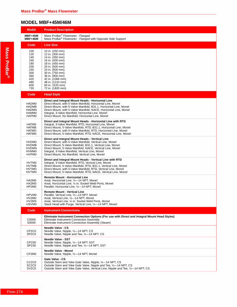
Flow-1
Mass ProBar ® Mass Flowmeter
Mass
ProB
ar®
MODEL MBF+45M/46MModel Product Description
MBF+45MMBF+46M
Mass ProBar® Flowmeter - FlangedMass ProBar® Flowmeter - Flanged with Opposite Side Support
Code Line Size
100120140160180200240300360420480600720
10 in. (250 mm)12 in. (300 mm)14 in. (350 mm)16 in. (400 mm)18 in. (450 mm)20 in. (500 mm)24 in. (600 mm)30 in. (750 mm)36 in. (900 mm)42 in. (1066 mm)48 in. (1210 mm)60 in. 1520 mm)72 in. (1820 mm)
Code Head Style
HADM0HADMBHADMNHAMM0HAPM0
Direct and Integral Mount Heads - Horizontal LineDirect Mount, with 5-Valve Manifold, Horizontal Line, MonelDirect Mount, with 5-Valve Manifold, B31.1, Horizontal Line, MonelDirect Mount, with 5-Valve Manifold, NACE, Horizontal Line, MonelIntegral, 3-Valve Manifold, Horizontal Line, MonelDirect Mount, No Manifold, Horizontal Line, Monel
HATM0HATMBHATMDHATMN
Direct and Integral Mount Heads - Horizontal Line with RTDIntegral, 3-Valve Manifold, RTD, Horizontal Line, MonelDirect Mount, 5-Valve Manifold, RTD, B31.1, Horizontal Line, MonelDirect Mount, with 5-Valve Manifold, RTD, Horizontal Line, MonelDirect Mount, 5-Valve Manifold, RTD, NACE, Horizontal Line, Monel
HVDM0HVDMBHVDMNHVMM0HVPM0
Direct and Integral Mount Heads - Vertical LineDirect Mount, with 5-Valve Manifold, Vertical Line, MonelDirect Mount, 5-Valve Manifold, B31.1, Vertical Line, MonelDirect Mount, 5-Valve Manifold, NACE, Vertical Line, MonelIntegral, 3-Valve Manifold, Vertical Line, MonelDirect Mount, No Manifold, Vertical Line, Monel
HVTM0HVTMBHVTMDHVTMN
Direct and Integral Mount Heads - Vertical Line with RTDIntegral, 3-Valve Manifold, RTD, Vertical Line, MonelDirect Mount, 5-Valve Manifold, RTD, B31.1, Vertical Line, MonelDirect Mount, with 5-Valve Manifold, RTD, Vertical Line, MonelDirect Mount, 5-Valve Manifold, RTD, NACE, Vertical Line, Monel
HA2M0HA2MSHP2M0
Remote Mount - Horizontal LineAxial, Horizontal Line, ½—14 NPT, MonelAxial, Horizontal Line, ½ in. Socket Weld Ports, MonelParallel, Horizontal Line, ½—14 NPT, Monel
HPVM0HV2M0HV2MSHSVM0
Remote Mount - Vertical LineParallel, Vertical Line, ½—14 NPT, MonelAxial, Vertical Line, ½—14 NPT, MonelAxial, Vertical Line, ½ in. Socket Weld Ports, MonelStack Head with Purge, Vertical Line, ½—14 NPT, Monel
Code Instrument Connections
C0000S0000
Eliminate Instrument Connection Options (For use with Direct and Integral Mount Head Styles)Eliminate Instrument Connection AssemblyEliminate Instrument Connection Assembly (Steam)
CP2C0SP2C0
Needle Valve - CSNeedle Valve, Nipple, ½—14 NPT, CSNeedle Valve, Nipple and Tee, ½—14 NPT, CS
CP2S0SP2S0
Needle Valve - SSTNeedle Valve, Nipple, ½—14 NPT, SSTNeedle Valve, Nipple and Tee, ½—14 NPT, SST
CP2M0Needle Valve - MonelNeedle Valve, Nipple, ½—14 NPT, Monel
CC2C0SC2C0SV2C0
Gate Valve - CSOutside Stem and Yoke Gate Valve, Nipple, ½—14 NPT, CSOutside Stem and Yoke Gate Valve, Nipple and Tee, ½—14 NPT, CSOutside Stem and Yoke Gate Valve, Vertical Line, Nipple and Tee, ½—14 NPT, CS
74

Rosemount Inc.
Mas
sP
roB
ar®
Code Instrument Connections (Continued)
CC2S0SC2S0SV2S0
Gate Valve - SSTOutside Stem and Yoke Gate Valve, Nipple, ½—14 NPT, SSTOutside Stem and Yoke Gate Valve, Nipple and Tee, Steam, ½—14 NPT, SSTOutside Stem and Yoke Gate Valve, Vertical Line, Nipple and Tee, ½—14 NPT, SST
Code Sensor Flanges
FCDM0FBDM0FADM0
3 in. ANSI Class 600, RF, Monel3 in. ANSI Class 300, RF, Monel3 in. ANSI Class 150, RF, Monel
Code Flanged Mount
FADCFADSFBDCFBDSFCDCFCDS
3 in. ANSI Class 150, Weld-Neck RF, CS3 in. ANSI Class 150, Weld-Neck RF, SST3 in. ANSI Class 300, Weld-Neck RF, CS3 in. ANSI Class 300, Weld-Neck RF, SST3 in. ANSI Class 600, Weld-Neck RF, CS3 in. ANSI Class 600, Weld-Neck RF, SST
Code DP Ranges
23
0–2.5 to 0–250 H2O (0–.62 to 0–62.2 kPa)0–10 to 0–830 H2O (0–2.48 to 0–206 kPa)
Code Static Pressure Ranges
34CD
0–8 to 0–800 psia (0–55.1 to 0–5515 kPa)0–36.26 to 0–3626 psia (250 to 25000 kPa)0–8 to 0–800 psig (0–55.1 to 0–5515 kPa)0–36.26 to 0–3626 psig (250 to 25000 kPa)
Code Output
A 4–20 mA with Digital Signal Based on HART
Code Fill Fluid
12
SiliconeInert Fill
Code Housing Material
ABCDJKLM
Epoxy-Poly-Aluminum ½—14 NPTEpoxy-Poly-Aluminum CM 20Epoxy-Poly-Aluminum PG 13.5Epoxy-Poly-Aluminum G½316 SST ½—14 NPT316 SST CM 20316 SST PG 13.5Epoxy-Poly-Aluminum G½
Code Opposite Side Support (Required for Model 46M ONLY)
MSDCWMSDSW
Contoured Weld Fitting and Cap, 3 in. BW, CSContoured Weld Fitting and Cap, 3 in. BW, SST
Code Optional Temperature Sensors (For Use with Remote Mount Head Styles.)
TRRTXRTRATRPTXATXP
Remote Thermowell and RTDRemote Thermowell and RTD, Explosion-ProofIntegral RTD, Axial HeadIntegral RTD, Parallel HeadIntegral RTD, Explosion-Proof, AxialIntegral RTD, Explosion-Proof, Parallel
Code Optional Manifolds
35678
Model 305 Manifold Bolted to Transmitter5-Valve Manifold, CS5-Valve Manifold, SST3-Valve Manifold, CS3-Valve Manifold, SST
Code Optional Mounting Brackets
K Coplanar Bracket, 2 in., Pipe/Panel, SST Bolts
MODEL MBF+45M/46M
Flow-175

Flow-1
Mass ProBar ® Mass Flowmeter
Mass
ProB
ar®
Code Optional Optional Meters
1 LCD Meter (Rate and Total)
Code Optional Hazardous Location Certificates
ABCDFH
FM Explosion-Proof ApprovalFM Explosion-Proof and Intrinsic Safety ApprovalCSA Explosion-Proof ApprovalCSA Explosion-Proof and Intrinsic Safety ApprovalKEMA/CENELEC Intrinsic Safety ApprovalKEMA/CENELEC Explosion-Proof Approval
Code Optional Calibration
MZOQSUWY
Lab Flow Calibration (Average K) (<10 in.)Special CalibrationLab Flow Calibration (Average K) (12 in.)Lab Flow Calibration (Average K) (14 in. to 16 in.)Lab Flow Calibration (Average K) (18 in. to 20 in.)Lab Flow Calibration (Average K) (24 in.)Lab Flow Calibration (Average K) (30 in.)Lab Flow Calibration (Average K) (36 in.)
Code Optional Quality Assurance
QA1Q21Q23Q29QJ2QM2QT1QT2QT8
Dieterich ProgramANSI B31.1ANSI B31.3NACE MR-0175-91Special Product DrawingASTM Material-Traceable (Sensor Only)Hydrostatic Test EP-4017Dye Penetrant ES-1012Extended Hydro EP-4046
Typical Model Number MBF+45M 240 HATM0 C0000 FADM0 FADC 2 3 A 1 A
MODEL MBF+45M/46M
76

Rosemount Inc.
Mas
sP
roB
ar®
Flow-177

Mass ProBar ® Mass Flowmeter
Mass
ProB
ar®
Flow-1
78
Rosemount Inc.
Mas
sP
roB
ar®
Flow-179

Mass ProBar ® Mass Flowmeter
Mass
ProB
ar®
Flow-1
80
Rosemount Inc.
Mas
sP
roB
ar®
Flow-181

Mass ProBar ® Mass Flowmeter
Flow-1
Mass
ProB
ar®
Ordering Information—Model MNTMODEL MNT+10S
Model Product Description
MNT+10S Mass ProBar® Flowmeter - In-line Threaded
Code Line Size
005007010012015020
½ in. (12.5 mm)¾ in. (19 mm)1 in. (25 mm)1¼ in. (31 mm)1½ in. (37.5 mm)2 in. (50 mm)
Code Fittings
HAMS0HADS0HADSBHADSNHAPS0
Direct and Integral Mount Heads - Horizontal LineIntegral, 3-Valve Manifold, Horizontal Line, SSTDirect Mount, with 5-Valve Manifold, Horizontal Line, SSTDirect Mount, with 5-Valve Manifold, B31.1, Horizontal Line, SSTDirect Mount, with 5-Valve Manifold, NACE, Horizontal Line, SSTDirect Mount, No Manifold, Horizontal Line, SST
HVMS0HVDS0HVDSBHVDSNHVPS0
Direct and Integral Mount Heads - Vertical LineIntegral, 3-Valve Manifold, Vertical Line, SSTDirect Mount, with 5-Valve Manifold, Vertical Line, SSTDirect Mount, 5-Valve Manifold, B31.1, Vertical Line, SSTDirect Mount, 5-Valve Manifold, NACE, Vertical Line, SSTDirect Mount, No Manifold, Vertical Line, SST
HF1SSHM1S0
Remote MountFittings, ¼ in. Socket Weld Ports, SSTFittings, ¼—18 NPT, SST
Code Instrument Connections
C0000S0000
Eliminate Instrument Connection Options (For use with Direct and Integral Mount Head Styles)Eliminate Instrument Connection AssemblyEliminate Instrument Connection Assembly (Steam)
CP1C0SP1C0
Needle Valve - CSNeedle Valve, Nipple, ¼—18 NPT, CSNeedle Valve, Nipple and Tee, ¼—18 NPT, CS
CP1S0SP1S0
Needle Valve - SSTNeedle Valve, Nipple, ¼—18 NPT, SSTNeedle Valve, Nipple and Tee, ¼—18 NPT, SST
SB1C0SB1S0
Gate ValveOutside Stem and Yoke Gate Valve, Elbow and Tee, ¼—18 NPT, CSOutside Stem and Yoke Gate Valve, Elbow and Tee, ¼—18 NPT, SST
Code DP Ranges
123
0-.5 to 0-25 in H2O (0-.12 to 0-6.22 kPa)0-2.5 to 0-250 H2O (0-.62 to 0-62.2 kPa)0-10 to 0-830 H2O (0-2.48 to 0-206 kPa)
Code Static Pressure Ranges
34CD
0-8 to 0-800 psia (0-55.1 to 0-5515 kPa)0-36.26 to 0-3626 psia (250 to 25000 kPa)0-8 to 0-800 psig (0-55.1 to 0-5515 kPa)0-36.26 to 0-3626 psig (250 to 25000 kPa)
Code Output
A 4—20 mA with Digital Signal Based on HART
Code Fill Fluid
12
SiliconeInert Fill
82

Rosemount Inc.
Mas
sP
roB
ar®
Code Housing Material
ABCDJKLM
Epoxy-Poly-Aluminum ½—14 NPTEpoxy-Poly-Aluminum CM 20Epoxy-Poly-Aluminum PG 13.5Epoxy-Poly-Aluminum G½316 SST ½—14 NPT316 SST CM 20316 SST PG 13.5Epoxy-Poly-Aluminum G½
Code Optional Temperature Sensors (For Use with Remote Mount Head Styles.)
TRRTXR
Remote Thermowell and RTDRemote Thermowell and RTD, Explosion-Proof
Code Optional Manifolds
35678
Model 305 Manifold Bolted to Transmitter5-Valve Manifold, CS5-Valve Manifold, SST3-Valve Manifold, CS3-Valve Manifold, SST
Code Optional Mounting Brackets
K Coplanar Bracket, 2 in., Pipe/Panel, SST Bolts
Code Optional Optional Meters
1 LCD Meter (Rate and Total)
Code Optional Hazardous Location Certificates
ABCDFH
FM Explosion-Proof ApprovalFM Explosion-Proof and Intrinsic Safety ApprovalCSA Explosion-Proof ApprovalCSA Explosion-Proof and Intrinsic Safety ApprovalKEMA/CENELEC Intrinsic Safety ApprovalKEMA/CENELEC Explosion-Proof Approval
Code Optional Calibration
MZ
Lab Flow Calibration (Average K) (<10 in.)Special Calibration
Code Optional Quality Assurance
QA1Q21Q23Q29QJ2QM2QT1QT2QT8
Dieterich ProgramANSI B31.1ANSI B31.3NACE MR-0175-91Special Product DrawingASTM Material-Traceable (Sensor Only)Hydrostatic Test EP-4017Dye Penetrant ES-1012Extended Hydro EP-4046
Typical Model Number MNT+10S 015 HAMS0 C0000 2 3 A 1 A TXR B
MODEL MNT+10S
Flow-183
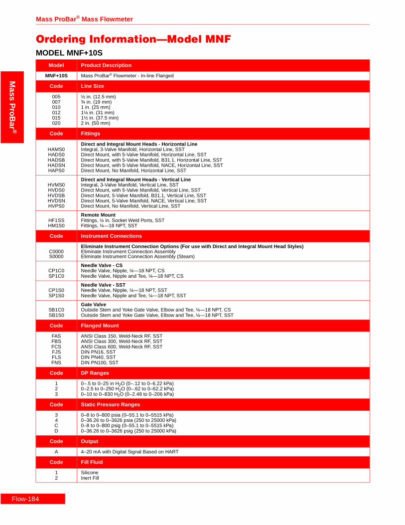
Flow-1
Mass ProBar ® Mass Flowmeter
Mass
ProB
ar®
Ordering Information—Model MNFMODEL MNF+10S
Model Product Description
MNF+10S Mass ProBar® Flowmeter - In-line Flanged
Code Line Size
005007010012015020
½ in. (12.5 mm)¾ in. (19 mm)1 in. (25 mm)1¼ in. (31 mm)1½ in. (37.5 mm)2 in. (50 mm)
Code Fittings
HAMS0HADS0HADSBHADSNHAPS0
Direct and Integral Mount Heads - Horizontal LineIntegral, 3-Valve Manifold, Horizontal Line, SSTDirect Mount, with 5-Valve Manifold, Horizontal Line, SSTDirect Mount, with 5-Valve Manifold, B31.1, Horizontal Line, SSTDirect Mount, with 5-Valve Manifold, NACE, Horizontal Line, SSTDirect Mount, No Manifold, Horizontal Line, SST
HVMS0HVDS0HVDSBHVDSNHVPS0
Direct and Integral Mount Heads - Vertical LineIntegral, 3-Valve Manifold, Vertical Line, SSTDirect Mount, with 5-Valve Manifold, Vertical Line, SSTDirect Mount, 5-Valve Manifold, B31.1, Vertical Line, SSTDirect Mount, 5-Valve Manifold, NACE, Vertical Line, SSTDirect Mount, No Manifold, Vertical Line, SST
HF1SSHM1S0
Remote MountFittings, ¼ in. Socket Weld Ports, SSTFittings, ¼—18 NPT, SST
Code Instrument Connections
C0000S0000
Eliminate Instrument Connection Options (For use with Direct and Integral Mount Head Styles)Eliminate Instrument Connection AssemblyEliminate Instrument Connection Assembly (Steam)
CP1C0SP1C0
Needle Valve - CSNeedle Valve, Nipple, ¼—18 NPT, CSNeedle Valve, Nipple and Tee, ¼—18 NPT, CS
CP1S0SP1S0
Needle Valve - SSTNeedle Valve, Nipple, ¼—18 NPT, SSTNeedle Valve, Nipple and Tee, ¼—18 NPT, SST
SB1C0SB1S0
Gate ValveOutside Stem and Yoke Gate Valve, Elbow and Tee, ¼—18 NPT, CSOutside Stem and Yoke Gate Valve, Elbow and Tee, ¼—18 NPT, SST
Code Flanged Mount
FASFBSFCSFJSFLSFNS
ANSI Class 150, Weld-Neck RF, SSTANSI Class 300, Weld-Neck RF, SSTANSI Class 600, Weld-Neck RF, SSTDIN PN16, SSTDIN PN40, SSTDIN PN100, SST
Code DP Ranges
123
0–.5 to 0–25 in H2O (0–.12 to 0–6.22 kPa)0–2.5 to 0–250 H2O (0–.62 to 0–62.2 kPa)0–10 to 0–830 H2O (0–2.48 to 0–206 kPa)
Code Static Pressure Ranges
34CD
0–8 to 0–800 psia (0–55.1 to 0–5515 kPa)0–36.26 to 0–3626 psia (250 to 25000 kPa)0–8 to 0–800 psig (0–55.1 to 0–5515 kPa)0–36.26 to 0–3626 psig (250 to 25000 kPa)
Code Output
A 4–20 mA with Digital Signal Based on HART
Code Fill Fluid
12
SiliconeInert Fill
84

Rosemount Inc.
Mas
sP
roB
ar®
Code Housing Material
ABCDJKLM
Epoxy-Poly-Aluminum ½—14 NPTEpoxy-Poly-Aluminum CM 20Epoxy-Poly-Aluminum PG 13.5Epoxy-Poly-Aluminum G½316 SST ½—14 NPT316 SST CM 20316 SST PG 13.5Epoxy-Poly-Aluminum G½
Code Optional Temperature Sensors (For Use with Remote Mount Head Styles.)
TRRTXR
Remote Thermowell and RTDRemote Thermowell and RTD, Explosion-Proof
Code Optional Manifolds
35678
Model 305 Manifold Bolted to Transmitter5-Valve Manifold, CS5-Valve Manifold, SST3-Valve Manifold, CS3-Valve Manifold, SST
Code Optional Mounting Brackets
K Coplanar Bracket, 2 in. Pipe/Panel, SST Bolts
Code Optional Optional Meters
1 LCD Meter (Rate and Total)
Code Optional Hazardous Location Certificates
ABCDFH
FM Explosion-Proof ApprovalFM Explosion-Proof and Intrinsic Safety ApprovalCSA Explosion-Proof ApprovalCSA Explosion-Proof and Intrinsic Safety ApprovalKEMA/CENELEC Intrinsic Safety ApprovalKEMA/CENELEC Explosion-Proof Approval
Code Optional Calibration
MZ
Lab Flow Calibration (Average K) (<10 in.)Special Calibration
Code Optional Quality Assurance
QA1Q21Q23Q29QJ2QM2QT1QT2QT8
Dieterich ProgramANSI B31.1ANSI B31.3NACE MR-0175-91Special Product DrawingASTM Material-Traceable (Sensor Only)Hydrostatic Test EP-4017Dye Penetrant ES-1012Extended Hydro EP-4046
Typical Model Number MNF+10S 015 HAMS0 C0000 FAS 1 3 A 1 A TRR 1
MODEL MNF+10S
Flow-185

Flow-1
Mass ProBar ® Mass Flowmeter
Mass
ProB
ar®
MODEL MNF+10HModel Product Description
MNF+10H Mass ProBar® Flowmeter - In-line Flanged
Code Line Size
005007010012015020
½ in. (12.5 mm)¾ in. (19 mm)1 in. (25 mm)1¼ in. (31 mm)1½ in. (37.5 mm)2 in. (50 mm)
Code Fittings
HADHNHADH0HADHBHAMH0HAPH0
Direct and Integral Mount Heads - Horizontal LineDirect Mount, with 5-Valve Manifold, NACE, Horizontal Line, Hastelloy-CDirect Mount, with 5-Valve Manifold, Horizontal Line, Hastelloy-CDirect Mount, with 5-Valve Manifold, B31.1, Horizontal Line, Hastelloy-CIntegral, 3-Valve Manifold, Horizontal Line, Hastelloy-CDirect Mount, No Manifold, Horizontal Line, Hastelloy-C
HVDHNHVDH0HVDHBHVMH0HVPH0
Direct and Integral Mount Heads - Vertical LineDirect Mount, 5-Valve Manifold, NACE, Vertical Line, Hastelloy-CDirect Mount, with 5-Valve Manifold, Vertical Line, Hastelloy-CDirect Mount, 5-Valve Manifold, B31.1, Vertical Line, Hastelloy-CIntegral, 3-Valve Manifold, Vertical Line, Hastelloy-CDirect Mount, No Manifold, Vertical Line, Hastelloy-C
HM1H0Remote MountFittings, ¼—18 NPT, Hastelloy-C
Code Instrument Connections
C0000S0000
Eliminate Instrument Connection Options (For use with Direct and Integral Mount Head Styles)Eliminate Instrument Connection AssemblyEliminate Instrument Connection Assembly (Steam)
CP1C0SP1C0
Needle Valve - CSNeedle Valve, Nipple, ¼—18 NPT, CSNeedle Valve, Nipple and Tee, ¼—18 NPT, CS
CP1S0SP1S0
Needle Valve - SSTNeedle Valve, Nipple, ¼—18 NPT, SSTNeedle Valve, Nipple and Tee, ¼—18 NPT, SST
SB1C0SB1S0
Gate ValveOutside Stem and Yoke Gate Valve, Elbow and Tee, ¼—18 NPT, CSOutside Stem and Yoke Gate Valve, Elbow and Tee, ¼—18 NPT, SST
Code Flanged Mount
FAHFBHFCH
ANSI Class 150, Weld-Neck RF, Hastelloy-CANSI Class 300, Weld-Neck RF, Hastelloy-CANSI Class 600, Weld-Neck RF, Hastelloy-C
Code DP Ranges
23
0–2.5 to 0–250 H2O (0–.62 to 0–62.2 kPa)0–10 to 0–830 H2O (0–2.48 to 0–206 kPa)
Code Static Pressure Ranges
34CD
0–8 to 0–800 psia (0–55.1 to 0–5515 kPa)0–36.26 to 0–3626 psia (250 to 25000 kPa)0–8 to 0–800 psig (0–55.1 to 0–5515 kPa)0–36.26 to 0–3626 psig (250 to 25000 kPa)
Code Output
A 4–20 mA with Digital Signal Based on HART
Code Fill Fluid
12
SiliconeInert Fill
86

Rosemount Inc.
Mas
sP
roB
ar®
Code Housing Material
ABCDJKLM
Epoxy-Poly-Aluminum ½—14 NPTEpoxy-Poly-Aluminum CM 20Epoxy-Poly-Aluminum PG 13.5Epoxy-Poly-Aluminum G½316 SST ½—14 NPT316 SST CM 20316 SST PG 13.5Epoxy-Poly-Aluminum G½
Code Optional Temperature Sensors (For Use with Remote Mount Head Styles.)
TRRTXR
Remote Thermowell and RTDRemote Thermowell and RTD, Explosion-Proof
Code Optional Manifolds
35678
Model 305 Manifold Bolted to Transmitter5-Valve Manifold, CS5-Valve Manifold, SST3-Valve Manifold, CS3-Valve Manifold, SST
Code Optional Mounting Brackets
K Coplanar Bracket, 2 in. Pipe/Panel, SST Bolts
Code Optional Optional Meters
1 LCD Meter (Rate and Total)
Code Optional Hazardous Location Certificates
ABCDFH
FM Explosion-Proof ApprovalFM Explosion-Proof and Intrinsic Safety ApprovalCSA Explosion-Proof ApprovalCSA Explosion-Proof and Intrinsic Safety ApprovalKEMA/CENELEC Intrinsic Safety ApprovalKEMA/CENELEC Explosion-Proof Approval
Code Optional Calibration
MZ
Lab Flow Calibration (Average K) (<10 in.)Special Calibration
Code Optional Quality Assurance
QA1Q21Q23Q29QJ2QM2QT1QT2QT8
Dieterich ProgramANSI B31.1ANSI B31.3NACE MR-0175-91Special Product DrawingASTM Material-Traceable (Sensor Only)Hydrostatic Test EP-4017Dye Penetrant ES-1012Extended Hydro EP-4046
Typical Model Number MNF+10H 015 HAMH0 C0000 FAH 2 3 A 1 A TRR 1
MODEL MNF+10H
Flow-187

Flow-1
Mass ProBar ® Mass Flowmeter
Mass
ProB
ar®
MODEL MNF+10MModel Product Description
MNF+10M Mass ProBar® Flowmeter - In-line Flanged
Code Line Size
005007010012015020
½ in. (12.5 mm)¾ in. (19 mm)1 in. (25 mm)1¼ in. (31 mm)1½ in. (37.5 mm)2 in. (50 mm)
Code Fittings
HADMNHADM0HADMBHAMM0HAPM0
Direct and Integral Mount Heads - Horizontal LineDirect Mount, with 5-Valve Manifold, NACE, Horizontal Line, MonelDirect Mount, with 5-Valve Manifold, Horizontal Line, MonelDirect Mount, with 5-Valve Manifold, B31.1, Horizontal Line, MonelIntegral, 3-Valve Manifold, Horizontal Line, MonelDirect Mount, No Manifold, Horizontal Line, Monel
HVDMNHVDM0HVDMBHVMM0HVPM0
Direct and Integral Mount Heads - Vertical LineDirect Mount, 5-Valve Manifold, NACE, Vertical Line, MonelDirect Mount, with 5-Valve Manifold, Vertical Line, MonelDirect Mount, 5-Valve Manifold, B31.1, Vertical Line, MonelIntegral, 3-Valve Manifold, Vertical Line, MonelDirect Mount, No Manifold, Vertical Line, Monel
HM1M0Remote MountFittings, ¼—18 NPT, Monel
Code Instrument Connections
C0000S0000
Eliminate Instrument Connection Options (For use with Direct and Integral Mount Head Styles)Eliminate Instrument Connection AssemblyEliminate Instrument Connection Assembly (Steam)
CP1C0SP1C0
Needle Valve - CSNeedle Valve, Nipple, ¼—18 NPT, CSNeedle Valve, Nipple and Tee, ¼—18 NPT, CS
P1S0SP1S0
Needle Valve - SSTNeedle Valve, Nipple, ¼—18 NPT, SSTNeedle Valve, Nipple and Tee, ¼—18 NPT, SST
SB1C0SB1S0
Gate ValveOutside Stem and Yoke Gate Valve, Elbow and Tee, ¼—18 NPT, CSOutside Stem and Yoke Gate Valve, Elbow and Tee, ¼—18 NPT, SST
Code Flanged Mount
FAMFBMFCM
ANSI Class 150, Weld-Neck RF, MonelANSI Class 300, Weld-Neck RF, MonelANSI Class 600, Weld-Neck RF, Monel
Code DP Ranges
23
0–2.5 to 0–250 H2O (0–.62 to 0–62.2 kPa)0–10 to 0–830 H2O (0–2.48 to 0–206 kPa)
Code Static Pressure Ranges
34CD
0–8 to 0–800 psia (0–55.1 to 0–5515 kPa)0–36.26 to 0–3626 psia (250 to 25000 kPa)0–8 to 0–800 psig (0–55.1 to 0–5515 kPa)0–36.26 to 0–3626 psig (250 to 25000 kPa)
Code Output
A 4–20 mA with Digital Signal Based on HART
Code Fill Fluid
12
SiliconeInert Fill
88

Rosemount Inc.
Mas
sP
roB
ar®
Code Housing Material
ABCDJKLM
Epoxy-Poly-Aluminum ½—14 NPTEpoxy-Poly-Aluminum CM 20Epoxy-Poly-Aluminum PG 13.5Epoxy-Poly-Aluminum G½316 SST ½—14 NPT316 SST CM 20316 SST PG 13.5Epoxy-Poly-Aluminum G½
Code Optional Temperature Sensors (For use with remote mount head styles)
TRRTXR
Remote Thermowell and RTDRemote Thermowell and RTD, Explosion-Proof
Code Optional Manifolds
35678
Model 305 Manifold Bolted to Transmitter5-Valve Manifold, CS5-Valve Manifold, SST3-Valve Manifold, CS3-Valve Manifold, SST
Code Optional Mounting Brackets
K Coplanar Bracket, 2 in. Pipe/Panel, SST Bolts
Code Optional Optional Meters
1 LCD Meter (Rate and Total)
Code Optional Hazardous Location Certificates
ABCDFH
FM Explosion-Proof ApprovalFM Explosion-Proof and Intrinsic Safety ApprovalCSA Explosion-Proof ApprovalCSA Explosion-Proof and Intrinsic Safety ApprovalKEMA/CENELEC Intrinsic Safety ApprovalKEMA/CENELEC Explosion-Proof Approval
Code Optional Calibration
MZ
Lab Flow Calibration (Average K) (<10 in.)Special Calibration
Code Optional Quality Assurance
QA1Q21Q23Q29QJ2QM2QT1QT2QT8
Dieterich ProgramANSI B31.1ANSI B31.3NACE MR-0175-91Special Product DrawingASTM Material-Traceable (Sensor Only)Hydrostatic Test EP-4017Dye Penetrant ES-1012Extended Hydro EP-4046
Typical Model Number MNF+10M 015 HAMM0 C0000 FAM 2 3 A 1 A TRR
MODEL MNF+10M
Flow-189

Flow-1
Mass ProBar ® Mass Flowmeter
Mass
ProB
ar®
Ordering Information—Model MNWMODEL MNW+10S
Model Product Description
MNW+10S Mass ProBar® Flowmeter - In-line Butt Weld
Code Line Size
005007010012015020
½ in. (12.5 mm)¾ in. (19 mm)1 in. (25 mm)1¼ in. (31 mm)1½ in. (37.5 mm)2 in. (50 mm)
Code Fittings
HAMS0HADS0HADSBHADSNHAPS0
Direct and Integral Mount Heads - Horizontal LineIntegral, 3-Valve Manifold, Horizontal Line, SSTDirect Mount, with 5-Valve Manifold, Horizontal Line, SSTDirect Mount, with 5-Valve Manifold, B31.1, Horizontal Line, SSTDirect Mount, with 5-Valve Manifold, NACE, Horizontal Line, SSTDirect Mount, No Manifold, Horizontal Line, SST
HVMS0HVDS0HVDSBHVDSNHVPS0
Direct and Integral Mount Heads - Vertical LineIntegral, 3-Valve Manifold, Vertical Line, SSTDirect Mount, with 5-Valve Manifold, Vertical Line, SSTDirect Mount, 5-Valve Manifold, B31.1, Vertical Line, SSTDirect Mount, 5-Valve Manifold, NACE, Vertical Line, SSTDirect Mount, No Manifold, Vertical Line, SST
HF1SSHM1S0
Remote MountFittings, ¼ in. Socket Weld Ports, SSTFittings, ¼—18 NPT, SST
Code Instrument Connections
C0000S0000
Eliminate Instrument Connection Options (For use with Direct and Integral Mount Head Styles)Eliminate Instrument Connection AssemblyEliminate Instrument Connection Assembly (Steam)
CP1C0SP1C0
Needle Valve - CSNeedle Valve, Nipple, ¼—18 NPT, CSNeedle Valve, Nipple and Tee, ¼—18 NPT, CS
CP1S0SP1S0
Needle Valve - SSTNeedle Valve, Nipple, ¼—18 NPT, SSTNeedle Valve, Nipple and Tee, ¼—18 NPT, SST
SB1C0SB1S0
Gate ValveOutside Stem and Yoke Gate Valve, Elbow and Tee, ¼—18 NPT, CSOutside Stem and Yoke Gate Valve, Elbow and Tee, ¼—18 NPT, SST
Code DP Ranges
123
0-.5 to 0-25 in H2O (0-.12 to 0-6.22 kPa)0-2.5 to 0-250 H2O (0-.62 to 0-62.2 kPa)0-10 to 0-830 H2O (0-2.48 to 0-206 kPa)
Code Static Pressure Ranges
34CD
0-8 to 0-800 psia (0-55.1 to 0-5515 kPa)0-36.26 to 0-3626 psia (250 to 25000 kPa)0-8 to 0-800 psig (0-55.1 to 0-5515 kPa)0-36.26 to 0-3626 psig (250 to 25000 kPa)
Code Output
A 4—20 mA with Digital Signal Based on HART
Code Fill Fluid
12
SiliconeInert Fill
90

Rosemount Inc.
Mas
sP
roB
ar®
Code Housing Material
ABCDJKLM
Epoxy-Poly-Aluminum ½—14 NPTEpoxy-Poly-Aluminum CM 20Epoxy-Poly-Aluminum PG 13.5Epoxy-Poly-Aluminum G½316 SST ½—14 NPT316 SST CM 20316 SST PG 13.5Epoxy-Poly-Aluminum G½
Code Optional Temperature Sensors (For use with remote mount head styles)
TRRTXR
Remote Thermowell and RTDRemote Thermowell and RTD, Explosion-Proof
Code Optional Manifolds
35678
Model 305 Manifold Bolted to Transmitter5-Valve Manifold, CS5-Valve Manifold, SST3-Valve Manifold, CS3-Valve Manifold, SST
Code Optional Mounting Brackets
K Coplanar Bracket, 2 in., Pipe/Panel, SST Bolts
Code Optional Optional Meters
1 LCD Meter (Rate and Total)
Code Optional Hazardous Location Certificates
ABCDFH
FM Explosion-Proof ApprovalFM Explosion-Proof and Intrinsic Safety ApprovalCSA Explosion-Proof ApprovalCSA Explosion-Proof and Intrinsic Safety ApprovalKEMA/CENELEC Intrinsic Safety ApprovalKEMA/CENELEC Explosion-Proof Approval
Code Optional Calibration
MZ
Lab Flow Calibration (Average K) (<10 in.)Special Calibration
Code Optional Quality Assurance
QA1Q21Q23Q29QJ2QM2QT1QT2QT8
Dieterich ProgramANSI B31.1ANSI B31.3NACE MR-0175-91Special Product DrawingASTM Material-Traceable (Sensor Only)Hydrostatic Test EP-4017Dye Penetrant ES-1012Extended Hydro EP-4046
Typical Model Number MNW+10S 015 HAMS0 C0000 2 3 A 1 B TXR H
MODEL MNW+10S
Flow-191

Mass ProBar ® Mass Flowmeter
Mass
ProB
ar®
Flow-1
92
Rosemount Inc.
Mas
sP
roB
ar®
Flow-193
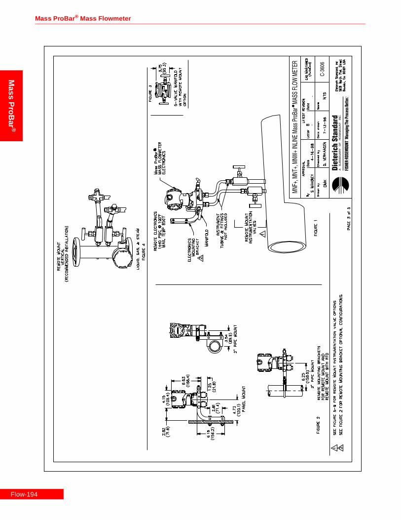
Mass ProBar ® Mass Flowmeter
Mass
ProB
ar®
Flow-1
94
Rosemount Inc.
Mas
sP
roB
ar®
Flow-195

Mass ProBar ® Mass Flowmeter
Mass
ProB
ar®
Flow-1
96
Rosemount Inc.
Mas
sP
roB
ar®
Flow-197
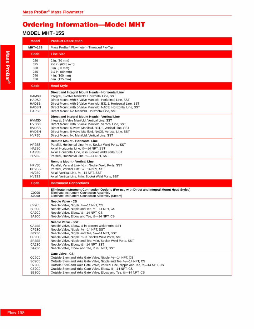
Flow-1
Mass ProBar ® Mass Flowmeter
Mass
ProB
ar®
Ordering Information—Model MHTMODEL MHT+15S
Model Product Description
MHT+15S Mass ProBar® Flowmeter - Threaded Flo-Tap
Code Line Size
020025030035040050
2 in. (50 mm)2½ in. (63.5 mm)3 in. (80 mm)3½ in. (89 mm)4 in. (100 mm)5 in. (125 mm)
Code Head Style
HAMS0HADS0HADSBHADSNHAPS0
Direct and Integral Mount Heads - Horizontal LineIntegral, 3-Valve Manifold, Horizontal Line, SSTDirect Mount, with 5-Valve Manifold, Horizontal Line, SSTDirect Mount, with 5-Valve Manifold, B31.1, Horizontal Line, SSTDirect Mount, with 5-Valve Manifold, NACE, Horizontal Line, SSTDirect Mount, No Manifold, Horizontal Line, SST
HVMS0HVDS0HVDSBHVDSNHVPS0
Direct and Integral Mount Heads - Vertical LineIntegral, 3-Valve Manifold, Vertical Line, SSTDirect Mount, with 5-Valve Manifold, Vertical Line, SSTDirect Mount, 5-Valve Manifold, B31.1, Vertical Line, SSTDirect Mount, 5-Valve Manifold, NACE, Vertical Line, SSTDirect Mount, No Manifold, Vertical Line, SST
HP2SSHA2S0HA2SSHP2S0
Remote Mount - Horizontal LineParallel, Horizontal Line, ½ in. Socket Weld Ports, SSTAxial, Horizontal Line, ½—14 NPT, SSTAxial, Horizontal Line, ½ in. Socket Weld Ports, SSTParallel, Horizontal Line, ½—14 NPT, SST
HPVS0HPVSSHV2S0HV2SS
Remote Mount - Vertical LineParallel, Vertical Line, ½ in. Socket Weld Ports, SSTParallel, Vertical Line, ½—14 NPT, SSTAxial, Vertical Line, ½—14 NPT, SSTAxial, Vertical Line, ½ in. Socket Weld Ports, SST
Code Instrument Connections
C0000S0000
Eliminate Instrument Connection Options (For use with Direct and Integral Mount Head Styles)Eliminate Instrument Connection AssemblyEliminate Instrument Connection Assembly (Steam)
CP2C0SP2C0CA2C0SA2C0
Needle Valve - CSNeedle Valve, Nipple, ½—14 NPT, CSNeedle Valve, Nipple and Tee, ½—14 NPT, CSNeedle Valve, Elbow, ½—14 NPT, CSNeedle Valve, Elbow and Tee, ½—14 NPT, CS
CA2SSCP2S0SP2S0CP2SSSP2SSCA2S0SA2S0
Needle Valve - SSTNeedle Valve, Elbow, ½ in. Socket Weld Ports, SSTNeedle Valve, Nipple, ½—14 NPT, SSTNeedle Valve, Nipple and Tee, ½—14 NPT, SSTNeedle Valve, Nipple, ½ in. Socket Weld Ports, SSTNeedle Valve, Nipple and Tee, ½ in. Socket Weld Ports, SSTNeedle Valve, Elbow, ½—14 NPT, SSTNeedle Valve, Elbow and Tee, ½ in., NPT, SST
CC2C0SC2C0SV2C0CB2C0SB2C0
Gate Valve - CSOutside Stem and Yoke Gate Valve, Nipple, ½—14 NPT, CSOutside Stem and Yoke Gate Valve, Nipple and Tee, ½—14 NPT, CSOutside Stem and Yoke Gate Valve, Vertical Line, Nipple and Tee, ½—14 NPT, CSOutside Stem and Yoke Gate Valve, Elbow, ½—14 NPT, CSOutside Stem and Yoke Gate Valve, Elbow and Tee, ½—14 NPT, CS
98

Rosemount Inc.
Mas
sP
roB
ar®
Code Instrument Connections (Continued)
CC2S0SC2S0SV2S0CB2SSCC2SSSV2SSCB2S0SB2S0
Gate Valve - SSTOutside Stem and Yoke Gate Valve, Nipple, ½—14 NPT, SSTOutside Stem and Yoke Gate Valve, Nipple and Tee, Steam, ½—14 NPT, SSTOutside Stem and Yoke Gate Valve, Vertical Line, Nipple and Tee, ½—14 NPT, SSTOutside Stem and Yoke Gate Valve, Elbow, ½ in. Socket Weld Ports, SSTOutside Stem and Yoke Gate Valve, Nipple, ½ in. Socket Weld Ports, SSTOutside Stem and Yoke Gate Valve, Vertical Line, Nipple and Tee, ½ in. Socket Weld Ports, SSTOutside Stem and Yoke Gate Valve, Elbow, ½—14 NPT, SSTOutside Stem and Yoke Gate Valve, Elbow and Tee, ½—14 NPT, SST
Code Packing Gland
GV3S0GV3C0GH3S0GH3C0
Graphite, ¾—14 NPT, SSTGraphite, ¾—14 NPT, CSUrethane, ¾—14 NPT, SSTUrethane, ¾—14 NPT, CS
Code Insert/Retract
IHRSIHRC
Manual, Dual, SST RodsManual, Dual, CS Rods
Code Isolation Valve
VT3SGVT3CG
Gate ValveGate Valve, ¾—14 NPT, SSTGate Valve, ¾—14 NPT, CS
VT3SBVT3CB
Ball ValveBall Valve, ¾—14 NPT, SSTBall Valve, ¾—14 NPT, CS
Code Mounting Hardware
MH3C0MH3S0
Weld Coupling and Nipple, ¾—14 NPT, CSWeld Coupling and Nipple, ¾—14 NPT, SST
Code DP Ranges
123
0-.5 to 0-25 in H2O (0-.12 to 0-6.22 kPa)0-2.5 to 0-250 H2O (0-.62 to 0-62.2 kPa)0-10 to 0-830 H2O (0-2.48 to 0-206 kPa)
Code Static Pressure Ranges
34CD
0-8 to 0-800 psia (0-55.1 to 0-5515 kPa)0-36.26 to 0-3626 psia (250 to 25000 kPa)0-8 to 0-800 psig (0-55.1 to 0-5515 kPa)0-36.26 to 0-3626 psig (250 to 25000 kPa)
Code Output
A 4—20 mA with Digital Signal Based on HART
Code Fill Fluid
12
SiliconeInert Fill
Code Housing Material
ABCDJKLM
Epoxy-Poly-Aluminum ½—14 NPTEpoxy-Poly-Aluminum CM 20Epoxy-Poly-Aluminum PG 13.5Epoxy-Poly-Aluminum G½316 SST ½—14 NPT316 SST CM 20316 SST PG 13.5Epoxy-Poly-Aluminum G½
Code Optional Temperature Sensors (For Use with Remote Mount Head Styles.)
TRRTXR
Remote Thermowell and RTDRemote Thermowell and RTD, Explosion-Proof
MODEL MHT+15S
Flow-199

Flow-2
Mass ProBar ® Mass Flowmeter
Mass
ProB
ar®
Code Optional Manifolds
35678
Model 305 Manifold Bolted to Transmitter5-Valve Manifold, CS5-Valve Manifold, SST3-Valve Manifold, CS3-Valve Manifold, SST
Code Optional Mounting Brackets
K Coplanar Bracket, 2 in., Pipe/Panel, SST Bolts
Code Optional Optional Meters
1 LCD Meter (Rate and Total)
Code Optional Hazardous Location Certificates
ABCDFH
FM Explosion-Proof ApprovalFM Explosion-Proof and Intrinsic Safety ApprovalCSA Explosion-Proof ApprovalCSA Explosion-Proof and Intrinsic Safety ApprovalKEMA/CENELEC Intrinsic Safety ApprovalKEMA/CENELEC Explosion-Proof Approval
Code Optional Calibration
MZ
Lab Flow Calibration (Average K) (<10 in.)Special Calibration
Code Optional Quality Assurance
QA1Q21Q23Q29QJ2QM2QT1QT2QT8
Dieterich ProgramANSI B31.1ANSI B31.3NACE MR-0175-91Special Product DrawingASTM Material-Traceable (Sensor Only)Hydrostatic Test EP-4017Dye Penetrant ES-1012Extended Hydro EP-4046
Typical Model Number MHT+15S 030 HAMS0 C0000 GV3S0 IHRS VT3SG MH3C0 1 3 A 1 A TRR
MODEL MHT+15S
00

Rosemount Inc.
Mas
sP
roB
ar®
MODEL MHT+25SModel Product Description
MHT+25S Mass ProBar® Flowmeter - Threaded Flo-Tap
Code Line Size
040050100120140160180200240300360420080060
4 in. (100 mm)5 in. (125 mm)10 in. (250 mm)12 in. (300 mm)14 in. (350 mm)16 in. (400 mm)18 in. (450 mm)20 in. (500 mm)24 in. (600 mm)30 in. (750 mm)36 in. (900 mm)42 in. (1066 mm)8 in. (200 mm)6 in. (150 mm)
Code Head Style
HAMS0HADS0HADSBHADSNHAPS0
Direct and Integral Mount Heads - Horizontal LineIntegral, 3-Valve Manifold, Horizontal Line, SSTDirect Mount, with 5-Valve Manifold, Horizontal Line, SSTDirect Mount, with 5-Valve Manifold, B31.1, Horizontal Line, SSTDirect Mount, with 5-Valve Manifold, NACE, Horizontal Line, SSTDirect Mount, No Manifold, Horizontal Line, SST
HATSNHATS0HATSDHATSB
Direct and Integral Mount Heads - Horizontal Line with RTDDirect Mount, 5-Valve Manifold, RTD, NACE, Horizontal Line, SSTIntegral, 3-Valve Manifold, RTD, Horizontal Line, SSTDirect Mount, with 5-Valve Manifold, RTD, Horizontal Line, SSTDirect Mount, 5-Valve Manifold, RTD, B31.1, Horizontal Line, SST
HVMS0HVDS0HVDSBHVDSNHVPS0
Direct and Integral Mount Heads - Vertical LineIntegral, 3-Valve Manifold, Vertical Line, SSTDirect Mount, with 5-Valve Manifold, Vertical Line, SSTDirect Mount, 5-Valve Manifold, B31.1, Vertical Line, SSTDirect Mount, 5-Valve Manifold, NACE, Vertical Line, SSTDirect Mount, No Manifold, Vertical Line, SST
HVTS0HVTSBHVTSDHVTSN
Direct and Integral Mount Heads - Vertical Line with RTDIntegral, 3-Valve Manifold, RTD, Vertical Line, SSTDirect Mount, 5-Valve Manifold, RTD, B31.1, Vertical Line, SSTDirect Mount, with 5-Valve Manifold, RTD, Vertical Line, SSTDirect Mount, 5-Valve Manifold, RTD, NACE, Vertical Line, SST
HP2SSHA2S0HA2SSHP2S0
Remote Mount - Horizontal LineParallel, Horizontal Line, ½ in. Socket Weld Ports, SSTAxial, Horizontal Line, ½—14 NPT, SSTAxial, Horizontal Line, ½ in. Socket Weld Ports, SSTParallel, Horizontal Line, ½—14 NPT, SST
HPVS0HPVSSHV2S0HV2SS
Remote Mount - Vertical LineParallel, Vertical Line, ½ in. Socket Weld Ports, SSTParallel, Vertical Line, ½—14 NPT, SSTAxial, Vertical Line, ½—14 NPT, SSTAxial, Vertical Line, ½ in. Socket Weld Ports, SST
Code Instrument Connections
C0000S0000
Eliminate Instrument Connection Options (For use with Direct and Integral Mount Head Styles)Eliminate Instrument Connection AssemblyEliminate Instrument Connection Assembly (Steam)
CP2C0SP2C0CA2C0SA2C0
Needle Valve - CSNeedle Valve, Nipple, ½—14 NPT, CSNeedle Valve, Nipple and Tee, ½—14 NPT, CSNeedle Valve, Elbow, ½—14 NPT, CSNeedle Valve, Elbow and Tee, ½—14 NPT, CS
CA2SSCP2S0SP2S0CP2SSSP2SSCA2S0SA2S0
Needle Valve - SSTNeedle Valve, Elbow, ½ in. Socket Weld Ports, SSTNeedle Valve, Nipple, ½—14 NPT, SSTNeedle Valve, Nipple and Tee, ½—14 NPT, SSTNeedle Valve, Nipple, ½ in. Socket Weld Ports, SSTNeedle Valve, Nipple and Tee, ½ in. Socket Weld Ports, SSTNeedle Valve, Elbow, ½—14 NPT, SSTNeedle Valve, Elbow and Tee, ½—14 NPT, SST
CC2C0SC2C0SV2C0CB2C0SB2C0
Gate Valve - CSOutside Stem and Yoke Gate Valve, Nipple, ½—14 NPT, CSOutside Stem and Yoke Gate Valve, Nipple and Tee, ½—14 NPT, CSOutside Stem and Yoke Gate Valve, Vertical Line, Nipple and Tee, ½—14 NPT, CSOutside Stem and Yoke Gate Valve, Elbow, ½—14 NPT, CSOutside Stem and Yoke Gate Valve, Elbow and Tee, ½—14 NPT, CS
Flow-201

Flow-2
Mass ProBar ® Mass Flowmeter
Mass
ProB
ar®
Code Instrument Connections (For use with Direct and Integral Mount Head Styles) (Continued)
CC2S0SC2S0SV2S0CB2SSCC2SSSV2SSCB2S0SB2S0
Gate Valve - SSTOutside Stem and Yoke Gate Valve, Nipple, ½—14 NPT, SSTOutside Stem and Yoke Gate Valve, Nipple and Tee, Steam, ½—14 NPT, SSTOutside Stem and Yoke Gate Valve, Vertical Line, Nipple and Tee, ½—14 NPT, SSTOutside Stem and Yoke Gate Valve, Elbow, ½ in. Socket Weld Ports, SSTOutside Stem and Yoke Gate Valve, Nipple, ½ in. Socket Weld Ports, SSTOutside Stem and Yoke Gate Valve, Vertical Line, Nipple and Tee, ½ in. Socket Weld Ports, SSTOutside Stem and Yoke Gate Valve, Elbow, ½—14 NPT, SSTOutside Stem and Yoke Gate Valve, Elbow and Tee, ½—14 NPT, SST
Code Packing Gland
GV5S0GV5C0GH5S0GH5C0
Graphite, 1¼—11.5 NPT, SSTGraphite, 1¼—11.5 NPT, CSUrethane, 1¼—11.5 NPT, SSTUrethane, 1¼—11.5 NPT, CS
Code Insert/Retract
IHRSIHRCIHDS
Manual, Dual, SST RodsManual, Dual, CS RodsGear, Dual, SST Rods
Code Isolation Valve
VT5SGVT5CG
Gate ValveGate Valve, 1¼—11.5 NPT, SSTGate Valve, 1¼—11.5 NPT, CS
VT5SBVT5CB
Ball ValveBall Valve, 1¼—11.5 NPT, SSTBall Valve, 1¼—11.5 NPT, CS
Code Mounting Hardware
MH5C0MH5S0
Weld Coupling and Nipple, 1¼—11.5 NPT, CSWeld Coupling and Nipple, 1¼—11.5 NPT, SST
Code DP Ranges
123
0-.5 to 0-25 in H2O (0-.12 to 0-6.22 kPa)0-2.5 to 0-250 H2O (0-.62 to 0-62.2 kPa)0-10 to 0-830 H2O (0-2.48 to 0-206 kPa)
Code Static Pressure Ranges
34CD
0-8 to 0-800 psia (0-55.1 to 0-5515 kPa)0-36.26 to 0-3626 psia (250 to 25000 kPa)0-8 to 0-800 psig (0-55.1 to 0-5515 kPa)0-36.26 to 0-3626 psig (250 to 25000 kPa)
Code Output
A 4—20 mA with Digital Signal Based on HART
Code Fill Fluid
12
SiliconeInert Fill
Code Housing Material
ABCDJKLM
Epoxy-Poly-Aluminum ½—14 NPTEpoxy-Poly-Aluminum CM 20Epoxy-Poly-Aluminum PG 13.5Epoxy-Poly-Aluminum G½316 SST ½—14 NPT316 SST CM 20316 SST PG 13.5Epoxy-Poly-Aluminum G½
MODEL MHT+25S
02

Rosemount Inc.
Mas
sP
roB
ar®
Code Optional Temperature Sensors (For Use with Remote Mount Head Styles.)
TRRTXRTRATRPTXATXP
Remote Thermowell and RTDRemote Thermowell and RTD, Explosion-ProofIntegral RTD, Axial HeadIntegral RTD, Parallel HeadIntegral RTD, Explosion, AxialIntegral RTD, Explosion-Proof, Parallel
Code Optional Manifolds
35678
Model 305 Manifold Bolted to Transmitter5-Valve Manifold, CS5-Valve Manifold, SST3-Valve Manifold, CS3-Valve Manifold, SST
Code Optional Mounting Brackets
K Coplanar Bracket, 2 in., Pipe/Panel, SST Bolts
Code Optional Optional Meters
1 LCD Meter (Rate and Total)
Code Optional Hazardous Location Certificates
ABCDFH
FM Explosion-Proof ApprovalFM Explosion-Proof and Intrinsic Safety ApprovalCSA Explosion-Proof ApprovalCSA Explosion-Proof and Intrinsic Safety ApprovalKEMA/CENELEC Intrinsic Safety ApprovalKEMA/CENELEC Explosion-Proof Approval
Code Optional Calibration
MZOQSUWY
Lab Flow Calibration (Average K) (<10 in.)Special CalibrationLab Flow Calibration (Average K) (12 in.)Lab Flow Calibration (Average K) (14 in. to 16 in.)Lab Flow Calibration (Average K) (18 in. to 20 in.)Lab Flow Calibration (Average K) (24 in.)Lab Flow Calibration (Average K) (30 in.)Lab Flow Calibration (Average K) (36 in.)
Code Optional Quality Assurance
QA1Q21Q23Q29QJ2QM2QT1QT2QT8
Dieterich ProgramANSI B31.1ANSI B31.3NACE MR-0175-91Special Product DrawingASTM Material-Traceable (Sensor Only)Hydrostatic Test EP-4017Dye Penetrant ES-1012Extended Hydro EP-4046
Typical Model Number MHT+25S 060 HATS0 C0000 GV5C0 IHRC VT5SG MH5C0 2 3 A 1 A B
MODEL MHT+25S
Flow-203

Flow-2
Mass ProBar ® Mass Flowmeter
Mass
ProB
ar®
MODEL MHT+35SModel Product Description
MHT+35S Mass ProBar® Flowmeter - Threaded Flo-Tap
Code Line Size
100120140160180200240300360420080480600720
10 in. (250 mm)12 in. (300 mm)14 in. (350 mm)16 in. (400 mm)18 in. (450 mm)20 in. (500 mm)24 in. (600 mm)30 in. (750 mm)36 in. (900 mm)42 in. (1066 mm)8 in. (200 mm)48 in. (1210 mm)60 in. 1520 mm)72 in. (1820 mm)
Code Head Style
HAMS0HADS0HADSBHADSNHAPS0
Direct and Integral Mount Heads - Horizontal LineIntegral, 3-Valve Manifold, Horizontal Line, SSTDirect Mount, with 5-Valve Manifold, Horizontal Line, SSTDirect Mount, with 5-Valve Manifold, B31.1, Horizontal Line, SSTDirect Mount, with 5-Valve Manifold, NACE, Horizontal Line, SSTDirect Mount, No Manifold, Horizontal Line, SST
HATSNHATS0HATSDHATSB
Direct and Integral Mount Heads - Horizontal Line with RTDDirect Mount, with 5-Valve Manifold, RTD, NACE, Horizontal Line, SSTIntegral, 3-Valve Manifold, RTD, Horizontal Line, SSTDirect Mount, with 5-Valve Manifold, RTD, Horizontal Line, SSTDirect Mount, with 5-Valve Manifold, RTD, B31.1, Horizontal Line, SST
HVMS0HVDS0HVDSBHVDSNHVPS0
Direct and Integral Mount Heads - Vertical LineIntegral, 3-Valve Manifold, Vertical Line, SSTDirect Mount, with 5-Valve Manifold, Vertical Line, SSTDirect Mount, 5-Valve Manifold, B31.1, Vertical Line, SSTDirect Mount, 5-Valve Manifold, NACE, Vertical Line, SSTDirect Mount, No Manifold, Vertical Line, SST
HVTS0HVTSBHVTSDHVTSN
Direct and Integral Mount Heads - Vertical Line with RTDIntegral, 3-Valve Manifold, RTD, Vertical Line, SSTDirect Mount, 5-Valve Manifold, RTD, B31.1, Vertical Line, SSTDirect Mount, with 5-Valve Manifold, RTD, Vertical Line, SSTDirect Mount, 5-Valve Manifold, RTD, NACE, Vertical Line, SST
HP2SSHA2S0HA2SSHP2S0
Remote Mount - Horizontal LineParallel, Horizontal Line, ½ in. Socket Weld Ports, SSTAxial, Horizontal Line, ½—14 NPT, SSTAxial, Horizontal Line, ½ in. Socket Weld Ports, SSTParallel, Horizontal Line, ½—14 NPT, SST
HPVS0HPVSSHV2S0HV2SS
Remote Mount - Vertical LineParallel, Vertical Line, ½ in. Socket Weld Ports, SSTParallel, Vertical Line, ½—14 NPT, SSTAxial, Vertical Line, ½—14 NPT, SSTAxial, Vertical Line, ½ in. Socket Weld Ports, SST
Code Instrument Connections
C0000S0000
Eliminate Instrument Connection Options (For use with Direct and Integral Mount Head Styles)Eliminate Instrument Connection AssemblyEliminate Instrument Connection Assembly (Steam)
CP2C0SP2C0CA2C0SA2C0
Needle Valve - CSNeedle Valve, Nipple, ½—14 NPT, CSNeedle Valve, Nipple and Tee, ½—14 NPT, CSNeedle Valve, Elbow, ½—14 NPT, CSNeedle Valve, Elbow and Tee, ½—14 NPT, CS
CA2SSCP2S0SP2S0CP2SSSP2SSCA2S0SA2S0
Needle Valve - SSTNeedle Valve, Elbow, ½ in. Socket Weld Ports, SSTNeedle Valve, Nipple, ½—14 NPT, SSTNeedle Valve, Nipple and Tee, ½—14 NPT, SSTNeedle Valve, Nipple, ½ in. Socket Weld Ports, SSTNeedle Valve, Nipple and Tee, ½ in. Socket Weld Ports, SSTNeedle Valve, Elbow, ½—14 NPT, SSTNeedle Valve, Elbow and Tee, ½—14 NPT, SST
CC2C0SC2C0SV2C0CB2C0SB2C0
Gate Valve - CSOutside Stem and Yoke Gate Valve, Nipple, ½—14 NPT, CSOutside Stem and Yoke Gate Valve, Nipple and Tee, ½—14 NPT, CSOutside Stem and Yoke Gate Valve, Vertical Line, Nipple and Tee, ½—14 NPT, CSOutside Stem and Yoke Gate Valve, Elbow, ½—14 NPT, CSOutside Stem and Yoke Gate Valve, Elbow and Tee, ½—14 NPT, CS
04

Rosemount Inc.
Mas
sP
roB
ar®
Code Instrument Connections (Continued)
CC2S0SC2S0SV2S0CB2SSCC2SSSV2SSCB2S0SB2S0
Gate Valve - SSTOutside Stem and Yoke Gate Valve, Nipple, ½—14 NPT, SSTOutside Stem and Yoke Gate Valve, Nipple and Tee, Steam, ½—14 NPT, SSTOutside Stem and Yoke Gate Valve, Vertical Line, Nipple and Tee, ½—14 NPT, SSTOutside Stem and Yoke Gate Valve, Elbow, ½ in. Socket Weld Ports, SSTOutside Stem and Yoke Gate Valve, Nipple, ½ in. Socket Weld Ports, SSTOutside Stem and Yoke Gate Valve, Vertical Line, Nipple and Tee, ½ in. Socket Weld Ports, SSTOutside Stem and Yoke Gate Valve, Elbow, ½—14 NPT, SSTOutside Stem and Yoke Gate Valve, Elbow and Tee, ½—14 NPT, SST
Code Packing Gland
GV8S0GV8C0GH8S0GH8C0
Graphite, 2—11.5 NPT, SSTGraphite, 2—11.5 NPT, CSUrethane, 2—11.5 NPT, SSTUrethane, 2—11.5 NPT, CS
Code Insert/Retract
IHRSIHRCIHDS
Manual, Dual, SST RodsManual, Dual, CS RodsGear, Dual, SST Rods
Code Isolation Valves
VT8SGVT8CG
Gate ValveGate Valve, 2—11.5 NPT, SSTGate Valve, 2—11.5 NPT, CS
VT8SBVT8CB
Ball ValveBall Valve, 2—11.5 NPT, SSTBall Valve, 2—11.5 NPT, CS
Code Mounting Hardware
MH8C0MH8S0
Weld Coupling and Nipple, 2—11.5 NPT, CSWeld Coupling and Nipple, 2—11.5 NPT, SST
Code DP Ranges
123
0-.5 to 0-25 in H2O (0-.12 to 0-6.22 kPa)0-2.5 to 0-250 H2O (0-.62 to 0-62.2 kPa)0-10 to 0-830 H2O (0-2.48 to 0-206 kPa)
Code Static Pressure Ranges
34CD
0-8 to 0-800 psia (0-55.1 to 0-5515 kPa)0-36.26 to 0-3626 psia (250 to 25000 kPa)0-8 to 0-800 psig (0-55.1 to 0-5515 kPa)0-36.26 to 0-3626 psig (250 to 25000 kPa)
Code Output
A 4—20 mA with Digital Signal Based on HART
Code Fill Fluid
12
SiliconeInert Fill
Code Housing Material
ABCDJKLM
Epoxy-Poly-Aluminum ½—14 NPTEpoxy-Poly-Aluminum CM 20Epoxy-Poly-Aluminum PG 13.5Epoxy-Poly-Aluminum G½316 SST ½—14 NPT316 SST CM 20316 SST PG 13.5Epoxy-Poly-Aluminum G½
MODEL MHT+35S
Flow-205
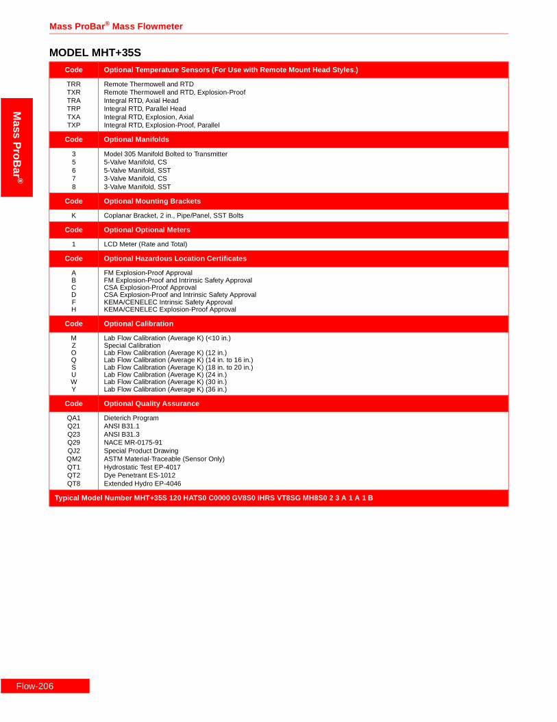
Flow-2
Mass ProBar ® Mass Flowmeter
Mass
ProB
ar®
Code Optional Temperature Sensors (For Use with Remote Mount Head Styles.)
TRRTXRTRATRPTXATXP
Remote Thermowell and RTDRemote Thermowell and RTD, Explosion-ProofIntegral RTD, Axial HeadIntegral RTD, Parallel HeadIntegral RTD, Explosion, AxialIntegral RTD, Explosion-Proof, Parallel
Code Optional Manifolds
35678
Model 305 Manifold Bolted to Transmitter5-Valve Manifold, CS5-Valve Manifold, SST3-Valve Manifold, CS3-Valve Manifold, SST
Code Optional Mounting Brackets
K Coplanar Bracket, 2 in., Pipe/Panel, SST Bolts
Code Optional Optional Meters
1 LCD Meter (Rate and Total)
Code Optional Hazardous Location Certificates
ABCDFH
FM Explosion-Proof ApprovalFM Explosion-Proof and Intrinsic Safety ApprovalCSA Explosion-Proof ApprovalCSA Explosion-Proof and Intrinsic Safety ApprovalKEMA/CENELEC Intrinsic Safety ApprovalKEMA/CENELEC Explosion-Proof Approval
Code Optional Calibration
MZOQSUWY
Lab Flow Calibration (Average K) (<10 in.)Special CalibrationLab Flow Calibration (Average K) (12 in.)Lab Flow Calibration (Average K) (14 in. to 16 in.)Lab Flow Calibration (Average K) (18 in. to 20 in.)Lab Flow Calibration (Average K) (24 in.)Lab Flow Calibration (Average K) (30 in.)Lab Flow Calibration (Average K) (36 in.)
Code Optional Quality Assurance
QA1Q21Q23Q29QJ2QM2QT1QT2QT8
Dieterich ProgramANSI B31.1ANSI B31.3NACE MR-0175-91Special Product DrawingASTM Material-Traceable (Sensor Only)Hydrostatic Test EP-4017Dye Penetrant ES-1012Extended Hydro EP-4046
Typical Model Number MHT+35S 120 HATS0 C0000 GV8S0 IHRS VT8SG MH8S0 2 3 A 1 A 1 B
MODEL MHT+35S
06

Rosemount Inc.
Mas
sP
roB
ar®
Flow-207

Mass ProBar ® Mass Flowmeter
Mass
ProB
ar®
Flow-2
08
Rosemount Inc.
Mas
sP
roB
ar®
Flow-209

Mass ProBar ® Mass Flowmeter
Mass
ProB
ar®
Flow-2
10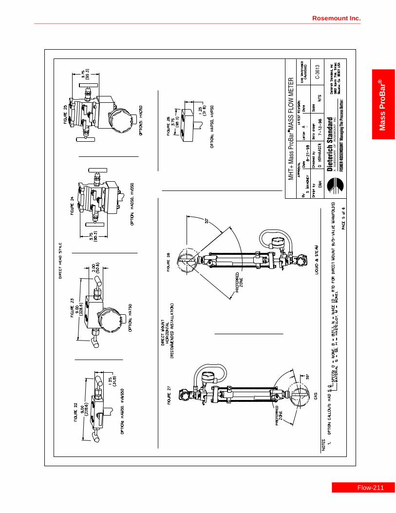
Rosemount Inc.
Mas
sP
roB
ar®
Flow-211

Mass ProBar ® Mass Flowmeter
Mass
ProB
ar®
Flow-2
12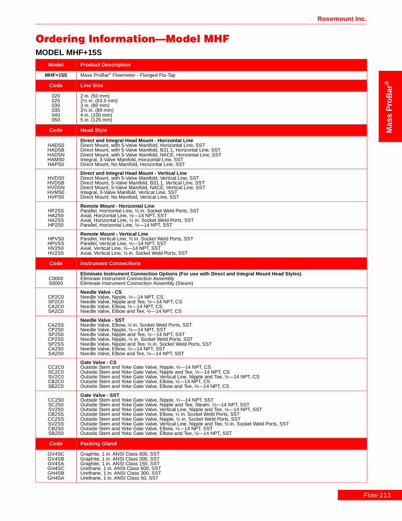
Rosemount Inc.
Mas
sP
roB
ar®
Ordering Information—Model MHFMODEL MHF+15S
Model Product Description
MHF+15S Mass ProBar® Flowmeter - Flanged Flo-Tap
Code Line Size
020025030035040050
2 in. (50 mm)2½ in. (63.5 mm)3 in. (80 mm)3½ in. (89 mm)4 in. (100 mm)5 in. (125 mm)
Code Head Style
HADS0HADSBHADSNHAMS0HAPS0
Direct and Integral Head Mount - Horizontal LineDirect Mount, with 5-Valve Manifold, Horizontal Line, SSTDirect Mount, with 5-Valve Manifold, B31.1, Horizontal Line, SSTDirect Mount, with 5-Valve Manifold, NACE, Horizontal Line, SSTIntegral, 3-Valve Manifold, Horizontal Line, SSTDirect Mount, No Manifold, Horizontal Line, SST
HVDS0HVDSBHVDSNHVMS0HVPS0
Direct and Integral Head Mount - Vertical LineDirect Mount, with 5-Valve Manifold, Vertical Line, SSTDirect Mount, 5-Valve Manifold, B31.1, Vertical Line, SSTDirect Mount, 5-Valve Manifold, NACE, Vertical Line, SSTIntegral, 3-Valve Manifold, Vertical Line, SSTDirect Mount, No Manifold, Vertical Line, SST
HP2SSHA2S0HA2SSHP2S0
Remote Mount - Horizontal LineParallel, Horizontal Line, ½ in. Socket Weld Ports, SSTAxial, Horizontal Line, ½—14 NPT, SSTAxial, Horizontal Line, ½ in. Socket Weld Ports, SSTParallel, Horizontal Line, ½—14 NPT, SST
HPVS0HPVSSHV2S0HV2SS
Remote Mount - Vertical LineParallel, Vertical Line, ½ in. Socket Weld Ports, SSTParallel, Vertical Line, ½—14 NPT, SSTAxial, Vertical Line, ½—14 NPT, SSTAxial, Vertical Line, ½ in. Socket Weld Ports, SST
Code Instrument Connections
C0000S0000
Eliminate Instrument Connection Options (For use with Direct and Integral Mount Head Styles)Eliminate Instrument Connection AssemblyEliminate Instrument Connection Assembly (Steam)
CP2C0SP2C0CA2C0SA2C0
Needle Valve - CSNeedle Valve, Nipple, ½—14 NPT, CSNeedle Valve, Nipple and Tee, ½—14 NPT, CSNeedle Valve, Elbow, ½—14 NPT, CSNeedle Valve, Elbow and Tee, ½—14 NPT, CS
CA2SSCP2S0SP2S0CP2SSSP2SSCA2S0SA2S0
Needle Valve - SSTNeedle Valve, Elbow, ½ in. Socket Weld Ports, SSTNeedle Valve, Nipple, ½—14 NPT, SSTNeedle Valve, Nipple and Tee, ½—14 NPT, SSTNeedle Valve, Nipple, ½ in. Socket Weld Ports, SSTNeedle Valve, Nipple and Tee, ½ in. Socket Weld Ports, SSTNeedle Valve, Elbow, ½—14 NPT, SSTNeedle Valve, Elbow and Tee, ½—14 NPT, SST
CC2C0SC2C0SV2C0CB2C0SB2C0
Gate Valve - CSOutside Stem and Yoke Gate Valve, Nipple, ½—14 NPT, CSOutside Stem and Yoke Gate Valve, Nipple and Tee, ½—14 NPT, CSOutside Stem and Yoke Gate Valve, Vertical Line, Nipple and Tee, ½—14 NPT, CSOutside Stem and Yoke Gate Valve, Elbow, ½—14 NPT, CSOutside Stem and Yoke Gate Valve, Elbow and Tee, ½—14 NPT, CS
CC2S0SC2S0SV2S0CB2SSCC2SSSV2SSCB2S0SB2S0
Gate Valve - SSTOutside Stem and Yoke Gate Valve, Nipple, ½—14 NPT, SSTOutside Stem and Yoke Gate Valve, Nipple and Tee, Steam, ½—14 NPT, SSTOutside Stem and Yoke Gate Valve, Vertical Line, Nipple and Tee, ½—14 NPT, SSTOutside Stem and Yoke Gate Valve, Elbow, ½ in. Socket Weld Ports, SSTOutside Stem and Yoke Gate Valve, Nipple, ½ in. Socket Weld Ports, SSTOutside Stem and Yoke Gate Valve, Vertical Line, Nipple and Tee, ½ in. Socket Weld Ports, SSTOutside Stem and Yoke Gate Valve, Elbow, ½—14 NPT, SSTOutside Stem and Yoke Gate Valve, Elbow and Tee, ½—14 NPT, SST
Code Packing Gland
GV4SCGV4SBGV4SAGH4SCGH4SBGH4SA
Graphite, 1 in. ANSI Class 600, SSTGraphite, 1 in. ANSI Class 300, SSTGraphite, 1 in. ANSI Class 150, SSTUrethane, 1 in. ANSI Class 600, SSTUrethane, 1 in. ANSI Class 300, SSTUrethane, 1 in. ANSI Class 50, SST
Flow-213

Flow-2
Mass ProBar ® Mass Flowmeter
Mass
ProB
ar®
Code Insert/Retract
IHRSIHRC
Manual, Dual, SST RodsManual, Dual, CS Rods
Code Isolation Valve
VC4SGVC4CGVB4SGVB4CGVA4SGVA4CG
Gate ValveGate Valve, 1 in. ANSI Class 600, SSTGate Valve, 1 in. ANSI Class 600, CSGate Valve, 1 in. ANSI Class 300, SSTGate Valve, 1 in. ANSI Class 300, CSGate Valve, 1 in. ANSI Class 150, SSTGate Valve, 1 in. ANSI Class 150, CS
VB4SBVB4CBVA4SBVA4CB
Ball ValveBall Valve, 1 in. ANSI Class 300, SSTBall Valve, 1 in. ANSI Class 300, CSBall Valve, 1 in. ANSI Class 150, SSTBall Valve, 1 in. ANSI Class 150, CS
Code Flanged Mount
FA4CFA4SFB4CFB4SFC4CFC4S
1 in. ANSI Class 150, Weld-Neck RF, CS1 in. ANSI Class 150, Weld-Neck RF, SST1 in. ANSI Class 300, Weld-Neck RF, CS1 in. ANSI Class 300, Weld-Neck RF, SST1 in. ANSI Class 600, Weld-Neck RF, CS1 in. ANSI Class 600, Weld-Neck RF, SST
Code DP Ranges
123
0–.5 to 0–25 in H2O (0–.12 to 0–6.22 kPa)0–2.5 to 0–250 H2O (0–.62 to 0–62.2 kPa)0–10 to 0–830 H2O (0–2.48 to 0–206 kPa)
Code Static Pressure Ranges
34CD
0–8 to 0–800 psia (0–55.1 to 0–5515 kPa)0–36.26 to 0–3626 psia (250 to 25000 kPa)0–8 to 0–800 psig (0–55.1 to 0–5515 kPa)0–36.26 to 0–3626 psig (250 to 25000 kPa)
Code Output
A 4–20 mA with Digital Signal Based on HART
Code Fill Fluid
12
SiliconeInert Fill
Code Housing Material
ABCDJKLM
Epoxy-Poly-Aluminum ½—14 NPTEpoxy-Poly-Aluminum CM 20Epoxy-Poly-Aluminum PG 13.5Epoxy-Poly-Aluminum G½316 SST ½—14 NPT316 SST CM 20316 SST PG 13.5Epoxy-Poly-Aluminum G½
Code Optional Temperature Sensors (For Use with Remote Mount Head Styles.)
TRRTXR
Remote Thermowell and RTDRemote Thermowell and RTD, Explosion-Proof
Code Optional Manifolds
35678
Model 305 Manifold Bolted to Transmitter5-Valve Manifold, CS5-Valve Manifold, SST3-Valve Manifold, CS3-Valve Manifold, SST
Code Optional Mounting Brackets
K Coplanar Bracket, 2 in., Pipe/Panel, SST Bolts
MODEL MHF+15S
14

Rosemount Inc.
Mas
sP
roB
ar®
Code Optional Optional Meters
1 LCD Meter (Rate and Total)
Code Optional Hazardous Location Certificates
ABCDFH
FM Explosion-Proof ApprovalFM Explosion-Proof and Intrinsic Safety ApprovalCSA Explosion-Proof ApprovalCSA Explosion-Proof and Intrinsic Safety ApprovalKEMA/CENELEC Intrinsic Safety ApprovalKEMA/CENELEC Explosion-Proof Approval
Code Optional Calibration
MZ
Lab Flow Calibration (Average K) (<10 in)Special Calibration
Code Optional Quality Assurance
QA1Q21Q23Q29QJ2QM2QT1QT2QT8
Dieterich ProgramANSI B31.1ANSI B31.3NACE MR–0175–91Special Product DrawingASTM Material-Traceable (Sensor Only)Hydrostatic Test EP-4017Dye Penetrant ES-1012Extended Hydro EP-4046
Typical Model Number MHF+15S 030 HAMS0 C0000 GV4SA IHRC VA4SG FA4S 1 3 A 1 A TRR
MODEL MHF+15S
Flow-215

Flow-2
Mass ProBar ® Mass Flowmeter
Mass
ProB
ar®
MODEL MHF+25SModel Product Description
MHF+25S Mass ProBar® Flowmeter - Flanged Flo-Tap
Code Line Size
040050060080100120140160180200240300360420
4 in. (100 mm)5 in. (125 mm)6 in. (150 mm)8 in. (200 mm)10 in. (250 mm)12 in. (300 mm)14 in. (350 mm)16 in. (400 mm)18 in. (450 mm)20 in. (500 mm)24 in. (600 mm)30 in. (750 mm)36 in. (900 mm)42 in. (1066 mm)
Code Head Style
HADS0HADSBHADSNHAMS0HAPS0
Direct and Integral Mount Heads - Horizontal LineDirect Mount, with 5-Valve Manifold, Horizontal Line, SSTDirect Mount, with 5-Valve Manifold, B31.1, Horizontal Line, SSTDirect Mount, with 5-Valve Manifold, NACE, Horizontal Line, SSTIntegral, 3-Valve Manifold, Horizontal Line, SSTDirect Mount, No Manifold, Horizontal Line, SST
HATSNHATS0HATSBHATSD
Direct and Integral Mount Heads - Horizontal Line with RTDDirect Mount, 5-Valve Manifold, RTD, NACE, Horizontal Line, SSTIntegral, 3-Valve Manifold, RTD, Horizontal Line, SSTDirect Mount, 5-Valve Manifold, RTD, B31.1, Horizontal Line, SSTDirect Mount, with 5-Valve Manifold, RTD, Horizontal Line, SST
HVDS0HVDSBHVDSNHVMS0HVPS0
Direct and Integral Mount Heads - Vertical LineDirect Mount, with 5-Valve Manifold, Vertical Line, SSTDirect Mount, 5-Valve Manifold, B31.1, Vertical Line, SSTDirect Mount, 5-Valve Manifold, NACE, Vertical Line, SSTIntegral, 3-Valve Manifold, Vertical Line, SSTDirect Mount, No Manifold, Vertical Line, SST
HVTS0HVTSBHVTSDHVTSN
Direct and Integral Mount Heads - Vertical Line with RTDIntegral, 3-Valve Manifold, RTD, Vertical Line, SSTDirect Mount, 5-Valve Manifold, RTD, B31.1, Vertical Line, SSTDirect Mount, with 5-Valve Manifold, RTD, Vertical Line, SSTDirect Mount, 5-Valve Manifold, RTD, NACE, Vertical Line, SST
HP2SSHA2S0HA2SSHP2S0
Remote Mount - Horizontal LineParallel, Horizontal Line, ½ in. Socket Weld Ports, SSTAxial, Horizontal Line, ½—14 NPT, SSTAxial, Horizontal Line, ½ in. Socket Weld Ports, SSTParallel, Horizontal Line, ½—14 NPT, SST
HPVS0HPVSSHV2S0HV2SS
Remote Mount - Vertical LineParallel, Vertical Line, ½ in. Socket Weld Ports, SSTParallel, Vertical Line, ½—14 NPT, SSTAxial, Vertical Line, ½—14 NPT, SSTAxial, Vertical Line, ½ in. Socket Weld Ports, SST
Code Instrument Connections
C0000S0000
Eliminate Instrument Connection Options (For use with Direct and Integral Mount Head Styles)Eliminate Instrument Connection AssemblyEliminate Instrument Connection Assembly (Steam)
CP2C0SP2C0CA2C0SA2C0
Needle Valve - CSNeedle Valve, Nipple, ½—14 NPT, CSNeedle Valve, Nipple and Tee, ½—14 NPT, CSNeedle Valve, Elbow, ½—14 NPT, CSNeedle Valve, Elbow and Tee, ½—14 NPT, CS
CA2SSCP2S0SP2S0CP2SSSP2SSCA2S0SA2S0
Needle Valve - SSTNeedle Valve, Elbow, ½ in. Socket Weld Ports, SSTNeedle Valve, Nipple, ½—14 NPT, SSTNeedle Valve, Nipple and Tee, ½—14 NPT, SSTNeedle Valve, Nipple, ½ in. Socket Weld Ports, SSTNeedle Valve, Nipple and Tee, ½ in. Socket Weld Ports, SSTNeedle Valve, Elbow, ½—14 NPT, SSTNeedle Valve, Elbow and Tee, ½—14 NPT, SST
16

Rosemount Inc.
Mas
sP
roB
ar®
Code Instrument Connections (Continued)
CC2C0SC2C0SV2C0CB2C0SB2C0
Gate Valve - CSOutside Stem and Yoke Gate Valve, Nipple, ½—14 NPT, CSOutside Stem and Yoke Gate Valve, Nipple and Tee, ½—14 NPT, CSOutside Stem and Yoke Gate Valve, Vertical Line, Nipple and Tee, ½—14 NPT, CSOutside Stem and Yoke Gate Valve, Elbow, ½—14 NPT, CSOutside Stem and Yoke Gate Valve, Elbow and Tee, ½—14 NPT, CS
CC2S0SC2S0SV2S0CB2SSCC2SSSV2SSCB2S0SB2S0
Gate Valve - SSTOutside Stem and Yoke Gate Valve, Nipple, ½—14 NPT, SSTOutside Stem and Yoke Gate Valve, Nipple and Tee, Steam, ½—14 NPT, SSTOutside Stem and Yoke Gate Valve, Vertical Line, Nipple and Tee, ½—14 NPT, SSTOutside Stem and Yoke Gate Valve, Elbow, ½ in. Socket Weld Ports, SSTOutside Stem and Yoke Gate Valve, Nipple, ½ in. Socket Weld Ports, SSTOutside Stem and Yoke Gate Valve, Vertical Line, Nipple and Tee, ½ in. Socket Weld Ports, SSTOutside Stem and Yoke Gate Valve, Elbow, ½—14 NPT, SSTOutside Stem and Yoke Gate Valve, Elbow and Tee, ½—14 NPT, SST
Code Packing Gland
GV6SCGV6SBGV6SAGH6SCGH6SBGH6SA
Graphite, 1½ in. ANSI Class 600, SSTGraphite, 1½ in. ANSI Class 300, SSTGraphite, 1½ in. ANSI Class 150, SSTUrethane, 1½ in. ANSI Class 600, SSTUrethane, 1½ in. ANSI Class 300, SSTUrethane, 1½ in. ANSI Class 150, SST
Code Insert/Retract
IHRSIHRCIHDSIHDC
Manual, Dual, SST RodsManual, Dual, CS RodsGear, Dual, SST RodsGear, Dual, CS Rods
Code Isolation Valve
VC6SGVC6CGVB6SGVB6CGVA6SGVA6CG
Gate ValveGate Valve, 1½ in. ANSI Class 600, SSTGate Valve, 1½ in. ANSI Class 600, CSGate Valve, 1½ in. ANSI Class 300, SSTGate Valve, 1½ in. ANSI Class 300, CSGate Valve, 1½ in. ANSI Class 150, SSTGate Valve, 1½ in. ANSI Class 150, CS
VB6SBVB6CBVA6SBVA6CB
Ball ValveBall Valve, 1½ in. ANSI Class 300, SSTBall Valve, 1½ in. ANSI Class 300, CSBall Valve, 1½ in. ANSI Class 150, SSTBall Valve, 1½ in. ANSI Class 150, CS
Code Flanged Mount
FA6CFA6SFB6CFB6SFC6CFC6S
11/2 in. ANSI Class 150, Weld-Neck RF, CS11/2 in. ANSI Class 150, Weld-Neck RF, SST11/2 in. ANSI Class 300, Weld-Neck RF, CS11/2 in. ANSI Class 300, Weld-Neck RF, SST11/2 in. ANSI Class 600, Weld-Neck RF, CS11/2 in. ANSI Class 600, Weld-Neck RF, SST
Code DP Ranges
123
0–.5 to 0–25 in H2O (0–.12 to 0–6.22 kPa)0–2.5 to 0–250 H2O (0–.62 to 0–62.2 kPa)0–10 to 0–830 H2O (0–2.48 to 0–206 kPa)
Code Static Pressure Ranges
34CD
0–8 to 0–800 psia (0–55.1 to 0–5515 kPa)0–36.26 to 0–3626 psia (250 to 25000 kPa)0–8 to 0–800 psig (0–55.1 to 0–5515 kPa)0–36.26 to 0–3626 psig (250 to 25000 kPa)
Code Output
A 4–20 mA with Digital Signal Based on HART
Code Fill Fluid
12
SiliconeInert Fill
MODEL MHF+25S
Flow-217

Flow-2
Mass ProBar ® Mass Flowmeter
Mass
ProB
ar®
Code Housing Material
ABCDJKLM
Epoxy-Poly-Aluminum ½—14 NPTEpoxy-Poly-Aluminum CM 20Epoxy-Poly-Aluminum PG 13.5Epoxy-Poly-Aluminum G½316 SST ½—14 NPT316 SST CM 20316 SST PG 13.5Epoxy-Poly-Aluminum G½
Code Optional Temperature Sensors (For Use with Remote Mount Head Styles.)
TRRTXRTRATRPTXATXP
Remote Thermowell and RTDRemote Thermowell and RTD, Explosion-ProofIntegral RTD, Axial HeadIntegral RTD, Parallel HeadIntegral RTD, Explosion, AxialIntegral RTD, Explosion-Proof, Parallel
Code Optional Manifolds
35678
Model 305 Manifold Bolted to Transmitter5-Valve Manifold, CS5-Valve Manifold, SST3-Valve Manifold, CS3-Valve Manifold, SST
Code Optional Mounting Brackets
K Coplanar Bracket, 2 in., Pipe/Panel, SST Bolts
Code Optional Meters
1 LCD Meter (Rate and Total)
Code Optional Hazardous Location Certificates
ABCDFH
FM Explosion-Proof ApprovalFM Explosion-Proof and Intrinsic Safety ApprovalCSA Explosion-Proof ApprovalCSA Explosion-Proof and Intrinsic Safety ApprovalKEMA/CENELEC Intrinsic Safety ApprovalKEMA/CENELEC Explosion-Proof Approval
Code Optional Calibration
MZOQSUWY
Lab Flow Calibration (Average K) (<10 in.)Special CalibrationLab Flow Calibration (Average K) (12 in.)Lab Flow Calibration (Average K) (14 in. to 16 in.)Lab Flow Calibration (Average K) (18 in. to 20 in.)Lab Flow Calibration (Average K) (24 in.)Lab Flow Calibration (Average K) (30 in.)Lab Flow Calibration (Average K) (36 in.)
Code Optional Quality Assurance
QA1Q21Q23Q29QJ2QM2QT1QT2QT8
Dieterich ProgramANSI B31.1ANSI B31.3NACE MR-0175-91Special Product DrawingASTM Material-Traceable (Sensor Only)Hydrostatic Test EP-4017Dye Penetrant ES-1012Extended Hydro EP-4046
Typical Model Number MHF+25S 060 HATS0 C0000 GV6SA IHRC VA6CG FA6C 2 3 A 1 B
MODEL MHF+25S
18

Rosemount Inc.
Mas
sP
roB
ar®
MODEL MHF+25HModel Product Description
MHF+25H Mass ProBar® Flowmeter - Flanged Flo-Tap
Code Line Size
040050060080100120140160180200240300360420
4 in. (100 mm)5 in. (125 mm)6 in. (150 mm)8 in. (200 mm)10 in. (250 mm)12 in. (300 mm)14 in. (350 mm)16 in. (400 mm)18 in. (450 mm)20 in. (500 mm)24 in. (600 mm)30 in. (750 mm)36 in. (900 mm)42 in. (1066 mm)
Code Head Style
HADH0HADHBHADHNHAMH0HAPH0
Direct and Integral Mount Heads - Horizontal LineDirect Mount, with 5-Valve Manifold, Horizontal Line, Hastelloy-CDirect Mount, with 5-Valve Manifold, B31.1, Horizontal Line, Hastelloy-CDirect Mount, with 5-Valve Manifold, NACE, Horizontal Line, Hastelloy-CIntegral, 3-Valve Manifold, Horizontal Line, Hastelloy-CDirect Mount, No Manifold, Horizontal Line, Hastelloy-C
HATH0HATHBHATHDHATHN
Direct and Integral Mount Heads - Horizontal Line with RTDIntegral, 3-Valve Manifold, RTD, Horizontal Line, Hastelloy-CDirect Mount, 5-Valve Manifold, RTD, B31.1, Horizontal Line, Hastelloy-CDirect Mount, with 5-Valve Manifold, RTD, Horizontal Line, Hastelloy-CDirect Mount, 5-Valve Manifold, RTD, NACE, Horizontal Line, Hastelloy-C
HVDH0HVDHBHVDHNHVMH0HVPH0
Direct and Integral Mount Heads - Vertical LineDirect Mount, with 5-Valve Manifold, Vertical Line, Hastelloy-CDirect Mount, 5-Valve Manifold, B31.1, Vertical Line, Hastelloy-CDirect Mount, 5-Valve Manifold, NACE, Vertical Line, Hastelloy-CIntegral, 3-Valve Manifold, Vertical Line, Hastelloy-CDirect Mount, No Manifold, Vertical Line, Hastelloy-C
HVTH0HVTHBHVTHDHVTHN
Direct and Integral Mount Heads - Vertical Line with RTDIntegral, 3-Valve Manifold, RTD, Vertical Line, Hastelloy-CDirect Mount, 5-Valve Manifold, RTD, B31.1, Vertical Line, Hastelloy-CDirect Mount, with 5-Valve Manifold, RTD, Vertical Line, Hastelloy-CDirect Mount, 5-Valve Manifold, RTD, NACE, Vertical Line, Hastelloy-C
HA2H0HA2HSHP2H0
Remote Mount - Horizontal LineAxial, Horizontal Line, ½—14 NPT, Hastelloy-CAxial, Horizontal Line, ½ in. Socket Weld Ports, Hastelloy-CParallel, Horizontal Line, ½—14 NPT, Hastelloy-C
HPVH0HV2H0
Remote Mount - Vertical LineParallel, Vertical Line, ½—14 NPT, Hastelloy-CAxial, Vertical Line, ½—14 NPT, Hastelloy-C
Code Instrument Connections
C0000S0000
Eliminate Instrument Connection Options (For use with Direct and Integral Mount Head Styles)Eliminate Instrument Connection AssemblyEliminate Instrument Connection Assembly (Steam)
CP2C0SP2C0CA2C0SA2C0
Needle Valve - CSNeedle Valve, Nipple, ½—14 NPT, CSNeedle Valve, Nipple and Tee, ½—14 NPT, CSNeedle Valve, Elbow, ½—14 NPT, CSNeedle Valve, Elbow and Tee, ½—14 NPT, CS
CP2S0SP2S0CA2S0SA2S0
Needle Valve - SSTNeedle Valve, Nipple, ½—14 NPT, SSTNeedle Valve, Nipple and Tee, ½—14 NPT, SSTNeedle Valve, Elbow, ½—14 NPT, SSTNeedle Valve, Elbow and Tee, ½—14 NPT, SST
CA2H0CP2H0
Needle Valve - HastelloyNeedle Valve, Elbow, ½—14 NPT, Hastelloy-CNeedle Valve, Nipple, ½—14 NPT, Hastelloy-C
CC2C0SC2C0SV2C0CB2C0SB2C0
Gate Valve - CSOutside Stem and Yoke Gate Valve, Nipple, ½—14 NPT, CSOutside Stem and Yoke Gate Valve, Nipple and Tee, ½—14 NPT, CSOutside Stem and Yoke Gate Valve, Vertical Line, Nipple and Tee, ½—14 NPT, CSOutside Stem and Yoke Gate Valve, Elbow, ½—14 NPT, CSOutside Stem and Yoke Gate Valve, Elbow and Tee, ½—14 NPT, CS
Flow-219

Flow-2
Mass ProBar ® Mass Flowmeter
Mass
ProB
ar®
Code Instrument Connections (Continued)
CC2S0SC2S0SV2S0CB2S0SB2S0
Gate Valve - SSTOutside Stem and Yoke Gate Valve, Nipple, ½—14 NPT, SSTOutside Stem and Yoke Gate Valve, Nipple and Tee, Steam, ½—14 NPT, SSTOutside Stem and Yoke Gate Valve, Vertical Line, Nipple and Tee, ½—14 NPT, SSTOutside Stem and Yoke Gate Valve, Elbow, ½—14 NPT, SSTOutside Stem and Yoke Gate Valve, Elbow and Tee, ½—14 NPT, SST
Code Packing Gland
GV6HCGV6HBGV6HA
Graphite, 1½ in. ANSI Class 600, Hastelloy-CGraphite, 1½ in. ANSI Class 300, Hastelloy-CGraphite, 1½ in. ANSI Class 150, Hastelloy-C
Code Insert/Retract
IHRSIHRCIHDSIHDC
Manual, Dual, SST RodsManual, Dual, CS RodsGear, Dual, SST RodsGear, Dual, CS Rods
Code Isolation Valve
VC6SGVC6CGVB6SGVB6CGVA6SGVA6CG
Gate ValveGate Valve, 1½ in. ANSI Class 600, SSTGate Valve, 1½ in. ANSI Class 600, CSGate Valve, 1½ in. ANSI Class 300, SSTGate Valve, 1½ in. ANSI Class 300, CSGate Valve, 1½ in. ANSI Class 150, SSTGate Valve, 1½ in. ANSI Class 150, CS
VB6SBVB6CBVA6SBVA6CB
Ball ValveBall Valve, 1½ in. ANSI Class 300, SSTBall Valve, 1½ in. ANSI Class 300, CSBall Valve, 1½ in. ANSI Class 150, SSTBall Valve, 1½ in. ANSI Class 150, CS
Code Flanged Mount
FA6CFA6SFB6CFB6SFC6CFC6S
1½ in. ANSI Class 150, Weld-Neck RF, CS1½ in. ANSI Class 150, Weld-Neck RF, SST1½ in. ANSI Class 300, Weld-Neck RF, CS1½ in. ANSI Class 300, Weld-Neck RF, SST1½ in. ANSI Class 600, Weld-Neck RF, CS1½ in. ANSI Class 600, Weld-Neck RF, SST
Code DP Ranges
23
0–2.5 to 0–250 H2O (0–.62 to 0–62.2 kPa)0–10 to 0–830 H2O (0–2.48 to 0–206 kPa)
Code Static Pressure Ranges
34CD
0–8 to 0–800 psia (0–55.1 to 0–5515 kPa)0–36.26 to 0–3626 psia (250 to 25000 kPa)0–8 to 0–800 psig (0–55.1 to 0–5515 kPa)0–36.26 to 0–3626 psig (250 to 25000 kPa)
Code Output
A 4–20 mA with Digital Signal Based on HART
Code Fill Fluid
12
SiliconeInert Fill
Code Housing Material
ABCDJKLM
Epoxy-Poly-Aluminum ½—14 NPTEpoxy-Poly-Aluminum CM 20Epoxy-Poly-Aluminum PG 13.5Epoxy-Poly-Aluminum G½316 SST ½—14 NPT316 SST CM 20316 SST PG 13.5Epoxy-Poly-Aluminum G½
MODEL MHF+25H
20

Rosemount Inc.
Mas
sP
roB
ar®
Code Optional Temperature Sensors (For Use with Remote Mount Head Styles.)
TRRTXRTRATRPTXATXP
Remote Thermowell and RTDRemote Thermowell and RTD, Explosion-ProofIntegral RTD, Axial HeadIntegral RTD, Parallel HeadIntegral RTD, Explosion, AxialIntegral RTD, Explosion-Proof, Parallel
Code Optional Manifolds
35678
Model 305 Manifold Bolted to Transmitter5-Valve Manifold, CS5-Valve Manifold, SST3-Valve Manifold, CS3-Valve Manifold, SST
Code Optional Mounting Brackets
K Coplanar Bracket, 2 in., Pipe/Panel, SST Bolts
Code Optional Meters
1 LCD Meter (Rate and Total)
Code Optional Hazardous Location Certificates
ABCDFH
FM Explosion-Proof ApprovalFM Explosion-Proof and Intrinsic Safety ApprovalCSA Explosion-Proof ApprovalCSA Explosion-Proof and Intrinsic Safety ApprovalKEMA/CENELEC Intrinsic Safety ApprovalKEMA/CENELEC Explosion-Proof Approval
Code Optional Calibration
MZOQSUWY
Lab Flow Calibration (Average K) (<10 in.)Special CalibrationLab Flow Calibration (Average K) (12 in.)Lab Flow Calibration (Average K) (14 in. to 16 in.)Lab Flow Calibration (Average K) (18 in. to 20 in.)Lab Flow Calibration (Average K) (24 in.)Lab Flow Calibration (Average K) (30 in.)Lab Flow Calibration (Average K) (36 in.)
Code Optional Quality Assurance
QA1Q21Q23Q29QJ2QM2QT1QT2QT8
Dieterich ProgramANSI B31.1ANSI B31.3NACE MR-0175-91Special Product DrawingASTM Material-Traceable (Sensor Only)Hydrostatic Test EP-4017Dye Penetrant ES-1012Extended Hydro EP-4046
Typical Model Number MHF+25H 060 HATH0 C0000 GV6HA IHRC VA6CG FA6C 2 3 A 1 A
MODEL MHF+25H
Flow-221

Flow-2
Mass ProBar ® Mass Flowmeter
Mass
ProB
ar®
MODEL MHF+25MModel Product Description
MHF+25M Mass ProBar® Flowmeter - Flanged Flo-Tap
Code Line Size
040050060080100120140160180200240280300360420
4 in. (100mm)5 in. (125 mm)6 in. (150 mm)8 in. (200 mm)10 in. (250 mm)12 in. (300 mm)14 in. (350 mm)16 in. (400 mm)18 in. (450 mm)20 in. (500 mm)24 in. (600 mm)28 in. (711 mm)30 in. (750 mm)36 in. (900 mm)42 in. (1066 mm)
Code Head Style
HADM0HADMBHADMNHAMM0HAPM0
Direct and Integral Mount Heads - Horizontal LineDirect Mount, with 5-Valve Manifold, Horizontal Line, MonelDirect Mount, with 5-Valve Manifold, B31.1, Horizontal Line, MonelDirect Mount, with 5-Valve Manifold, NACE, Horizontal Line, MonelIntegral, 3-Valve Manifold, Horizontal Line, MonelDirect Mount, No Manifold, Horizontal Line, Monel
HATM0HATMBHATMDHATMN
Direct and Integral Mount Heads - Horizontal Line with RTDIntegral, 3-Valve Manifold, RTD, Horizontal Line, MonelDirect Mount, 5-Valve Manifold, RTD, B31.1, Horizontal Line, MonelDirect Mount, with 5-Valve Manifold, RTD, Horizontal Line, MonelDirect Mount, 5-Valve Manifold, RTD, NACE, Horizontal Line, Monel
HVDM0HVDMBHVDMNHVMM0HVPM0
Direct and Integral Mount Heads - Vertical LineDirect Mount, with 5-Valve Manifold, Vertical Line, MonelDirect Mount, 5-Valve Manifold, B31.1, Vertical Line, MonelDirect Mount, 5-Valve Manifold, NACE, Vertical Line, MonelIntegral, 3-Valve Manifold, Vertical Line, MonelDirect Mount, No Manifold, Vertical Line, Monel
HVTM0HVTMBHVTMDHVTMN
Direct and Integral Mount Heads - Vertical Line with RTDIntegral, 3-Valve Manifold, RTD, Vertical Line, MonelDirect Mount, 5-Valve Manifold, RTD, B31.1, Vertical Line, MonelDirect Mount, with 5-Valve Manifold, RTD, Vertical Line, MonelDirect Mount, 5-Valve Manifold, RTD, NACE, Vertical Line, Monel
HA2M0HA2MSHP2M0
Remote Mount - Horizontal LineAxial, Horizontal Line, ½—14 NPT, MonelAxial, Horizontal Line, ½ in. Socket Weld Ports, MonelParallel, Horizontal Line, ½—14 NPT, Monel
HPVM0HV2M0HV2MS
Remote Mount - Vertical LineParallel, Vertical Line, ½—14 NPT, MonelAxial, Vertical Line, ½—14 NPT, MonelAxial, Vertical Line, ½ in. Socket Weld Ports, Monel
Code Instrument Connections
C0000S0000
Eliminate Instrument Connection Options (For use with Direct and Integral Mount Head Styles)Eliminate Instrument Connection AssemblyEliminate Instrument Connection Assembly (Steam)
CP2C0SP2C0CA2C0SA2C0
Needle Valve - CSNeedle Valve, Nipple, ½—14 NPT, CSNeedle Valve, Nipple and Tee, ½—14 NPT, CSNeedle Valve, Elbow, ½—14 NPT, CSNeedle Valve, Elbow and Tee, ½—14 NPT, CS
CP2S0SP2S0CA2S0SA2S0
Needle Valve - SSTNeedle Valve, Nipple, ½—14 NPT, SSTNeedle Valve, Nipple and Tee, ½—14 NPT, SSTNeedle Valve, Elbow, ½—14 NPT, SSTNeedle Valve, Elbow and Tee, ½—14 NPT, SS
CP2M0CA2M0
Needle Valve - MonelNeedle Valve, Nipple, ½—14 NPT, MonelNeedle Valve, Elbow, ½—14 NPT, Monel
CC2C0SC2C0SV2C0CB2C0SB2C0
Gate Valve - CSOutside Stem and Yoke Gate Valve, Nipple, ½—14 NPT, CSOutside Stem and Yoke Gate Valve, Nipple and Tee, ½—14 NPT, CSOutside Stem and Yoke Gate Valve, Vertical Line, Nipple and Tee, ½—14 NPT, CSOutside Stem and Yoke Gate Valve, Elbow, ½—14 NPT, CSOutside Stem and Yoke Gate Valve, Elbow and Tee, ½—14 NPT, CS
22
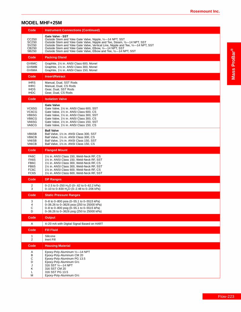
Rosemount Inc.
Mas
sP
roB
ar®
Code Instrument Connections (Continued)
CC2S0SC2S0SV2S0CB2S0SB2S0
Gate Valve - SSTOutside Stem and Yoke Gate Valve, Nipple, ½—14 NPT, SSTOutside Stem and Yoke Gate Valve, Nipple and Tee, Steam, ½—14 NPT, SSTOutside Stem and Yoke Gate Valve, Vertical Line, Nipple and Tee, ½—14 NPT, SSTOutside Stem and Yoke Gate Valve, Elbow, ½—14 NPT, SSTOutside Stem and Yoke Gate Valve, Elbow and Tee, ½—14 NPT, SST
Code Packing Gland
GV6MCGV6MBGV6MA
Graphite, 1½ in. ANSI Class 600, MonelGraphite, 1½ in. ANSI Class 300, MonelGraphite, 1½ in. ANSI Class 150, Monel
Code Insert/Retract
IHRSIHRCIHDSIHDC
Manual, Dual, SST RodsManual, Dual, CS RodsGear, Dual, SST RodsGear, Dual, CS Rods
Code Isolation Valve
VC6SGVC6CGVB6SGVB6CGVA6SGVA6CG
Gate ValveGate Valve, 1½ in. ANSI Class 600, SSTGate Valve, 1½ in. ANSI Class 600, CSGate Valve, 1½ in. ANSI Class 300, SSTGate Valve, 1½ in. ANSI Class 300, CSGate Valve, 1½ in. ANSI Class 150, SSTGate Valve, 1½ in. ANSI Class 150, CS
VB6SBVB6CBVA6SBVA6CB
Ball ValveBall Valve, 1½ in. ANSI Class 300, SSTBall Valve, 1½ in. ANSI Class 300, CSBall Valve, 1½ in. ANSI Class 150, SSTBall Valve, 1½ in. ANSI Class 150, CS
Code Flanged Mount
FA6CFA6SFB6CFB6SFC6CFC6S
1½ in. ANSI Class 150, Weld-Neck RF, CS1½ in. ANSI Class 150, Weld-Neck RF, SST1½ in. ANSI Class 300, Weld-Neck RF, CS1½ in. ANSI Class 300, Weld-Neck RF, SST1½ in. ANSI Class 600, Weld-Neck RF, CS1½ in. ANSI Class 600, Weld-Neck RF, SST
Code DP Ranges
23
0–2.5 to 0–250 H2O (0–.62 to 0–62.2 kPa)0–10 to 0–830 H2O (0–2.48 to 0–206 kPa)
Code Static Pressure Ranges
34CD
0–8 to 0–800 psia (0–55.1 to 0–5515 kPa)0–36.26 to 0–3626 psia (250 to 25000 kPa)0–8 to 0–800 psig (0–55.1 to 0–5515 kPa)0–36.26 to 0–3626 psig (250 to 25000 kPa)
Code Output
A 4–20 mA with Digital Signal Based on HART
Code Fill Fluid
12
SiliconeInert Fill
Code Housing Material
ABCDJKLM
Epoxy-Poly-Aluminum ½—14 NPTEpoxy-Poly-Aluminum CM 20Epoxy-Poly-Aluminum PG 13.5Epoxy-Poly-Aluminum G½316 SST ½—14 NPT316 SST CM 20316 SST PG 13.5Epoxy-Poly-Aluminum G½
MODEL MHF+25M
Flow-223

Flow-2
Mass ProBar ® Mass Flowmeter
Mass
ProB
ar®
Code Optional Temperature Sensors (For Use with Remote Mount Head Styles.)
TRRTXRTRATRPTXATXP
Remote Thermowell and RTDRemote Thermowell and RTD, Explosion-ProofIntegral RTD, Axial HeadIntegral RTD, Parallel HeadIntegral RTD, Explosion, AxialIntegral RTD, Explosion-Proof, Parallel
Code Optional Manifolds
35678
Model 305 Manifold Bolted to Transmitter5-Valve Manifold, CS5-Valve Manifold, SST3-Valve Manifold, CS3-Valve Manifold, SST
Code Optional Mounting Brackets
K Coplanar Bracket, 2 in., Pipe/Panel, SST Bolts
Code Optional Meters
1 LCD Meter (Rate and Total)
Code Optional Hazardous Location Certificates
ABCDFH
FM Explosion-Proof ApprovalFM Explosion-Proof and Intrinsic Safety ApprovalCSA Explosion-Proof ApprovalCSA Explosion-Proof and Intrinsic Safety ApprovalKEMA/CENELEC Intrinsic Safety ApprovalKEMA/CENELEC Explosion-Proof Approval
Code Optional Calibration
MZOQSUWY
Lab Flow Calibration (Average K) (<10 in.)Special CalibrationLab Flow Calibration (Average K) (12 in.)Lab Flow Calibration (Average K) (14 in. to 16 in.)Lab Flow Calibration (Average K) (18 in. to 20 in.)Lab Flow Calibration (Average K) (24 in.)Lab Flow Calibration (Average K) (30 in.)Lab Flow Calibration (Average K) (36 in.)
Code Optional Quality Assurance
QA1Q21Q23Q29QJ2QM2QT1QT2QT8
Dieterich ProgramANSI B31.1ANSI B31.3NACE MR-0175-91Special Product DrawingASTM Material-Traceable (Sensor Only)Hydrostatic Test EP-4017Dye Penetrant ES-1012Extended Hydro EP-4046
Typical Model Number MHF+25M 060 HATM0 C0000 GV6MA IHRC VA6CG FA6C 2 3 A 1 A
MODEL MHF+25M
24

Rosemount Inc.
Mas
sP
roB
ar®
MODEL MHF+35SModel Product Description
MHF+35S Mass ProBar® Flowmeter - Flanged Flo-Tap
Code Line Size
100120140160180200240300360420080480600720
10 in. (250 mm)12 in. (300 mm)14 in. (350 mm)16 in. (400 mm)18 in. (450 mm)20 in. (500 mm)24 in. (600 mm)30 in. (750 mm)36 in. (900 mm)42 in. (1066 mm)8 in. (200 mm)48 in. (1210 mm)60 in. (1520 mm)72 in. (1820 mm)
Code Head Style
HADS0HADSBHADSNHAMS0HAPS0
Direct and Integral Mount Heads - Horizontal LineDirect Mount, with 5-Valve Manifold, Horizontal Line, SSTDirect Mount, with 5-Valve Manifold, B31.1, Horizontal Line, SSTDirect Mount, with 5-Valve Manifold, NACE, Horizontal Line, SSTIntegral, 3-Valve Manifold, Horizontal Line, SSTDirect Mount, No Manifold, Horizontal Line, SST
HATSNHATS0HATSDHATSB
Direct and Integral Mount Heads - Horizontal Line with RTDDirect Mount, 5-Valve Manifold, RTD, NACE, Horizontal Line, SSTIntegral, 3-Valve Manifold, RTD, Horizontal Line, SSTDirect Mount, with 5-Valve Manifold, RTD, Horizontal Line, SSTDirect Mount, with 5-Valve Manifold, RTD, B31.1, Horizontal Line, SST
HVDS0HVDSBHVDSNHVMS0HVPS0
Direct and Integral Mount Heads - Vertical LineDirect Mount, with 5-Valve Manifold, Vertical Line, SSTDirect Mount, 5-Valve Manifold, B31.1, Vertical Line, SSTDirect Mount, 5-Valve Manifold, NACE, Vertical Line, SSTIntegral, 3-Valve Manifold, Vertical Line, SSTDirect Mount, No Manifold, Vertical Line, SST
HVTS0HVTSBHVTSDHVTSN
Direct and Integral Mount Heads - Vertical Line with RTDIntegral, 3-Valve Manifold, RTD, Vertical Line, SSTDirect Mount, 5-Valve Manifold, RTD, B31.1, Vertical Line, SSTDirect Mount, with 5-Valve Manifold, RTD, Vertical Line, SSTDirect Mount, 5-Valve Manifold, RTD, NACE, Vertical Line, SST
HP2SSHA2S0HA2SSHP2S0
Remote Mount - Horizontal LineParallel, Horizontal Line, ½ in. Socket Weld Ports, SSTAxial, Horizontal Line, ½—14 NPT, SSTAxial, Horizontal Line, ½ in. Socket Weld Ports, SSTParallel, Horizontal Line, ½—14 NPT, SST
HPVS0HPVSSHV2S0HV2SS
Remote Mount - Vertical LineParallel, Vertical Line, ½ in. Socket Weld Ports, SSTParallel, Vertical Line, ½—14 NPT, SSTAxial, Vertical Line, ½—14 NPT, SSTAxial, Vertical Line, ½ in. Socket Weld Ports, SST
Code Instrument Connections
C0000S0000
Eliminate Instrument Connection Options (For use with Direct and Integral Mount Head Styles)Eliminate Instrument Connection AssemblyEliminate Instrument Connection Assembly (Steam)
CP2C0SP2C0CA2C0SA2C0
Needle Valve - CSNeedle Valve, Nipple, ½—14 NPT, CSNeedle Valve, Nipple and Tee, ½—14 NPT, CSNeedle Valve, Elbow, ½—14 NPT, CSNeedle Valve, Elbow and Tee, ½—14 NPT, CS
CA2SSCP2S0SP2S0CA2S0SA2S0CP2SSSP2SS
Needle Valve - SSTNeedle Valve, Elbow, ½ in. Socket Weld Ports, SSTNeedle Valve, Nipple, ½—14 NPT, SSTNeedle Valve, Nipple and Tee, ½—14 NPT, SSTNeedle Valve, Elbow, ½—14 NPT, SSTNeedle Valve, Elbow and Tee, ½—14 NPT, SSTNeedle Valve, Nipple, ½ in. Socket Weld Ports, SSTNeedle Valve, Nipple and Tee, ½ in. Socket Weld Ports, SST
CC2C0SC2C0SV2C0CB2C0SB2C0
Gate Valve - CSOutside Stem and Yoke Gate Valve, Nipple, ½—14 NPT, CSOutside Stem and Yoke Gate Valve, Nipple and Tee, ½—14 NPT, CSOutside Stem and Yoke Gate Valve, Vertical Line, Nipple and Tee, ½—14 NPT, CSOutside Stem and Yoke Gate Valve, Elbow, ½—14 NPT, CSOutside Stem and Yoke Gate Valve, Elbow and Tee, ½—14 NPT, CS
Flow-225

Flow-2
Mass ProBar ® Mass Flowmeter
Mass
ProB
ar®
Code Instrument Connections (Continued)
CC2S0SC2S0SV2S0CB2S0SB2S0CB2SSCC2SSSV2SS
Gate Valve - SSTOutside Stem and Yoke Gate Valve, Nipple, ½—14 NPT, SSTOutside Stem and Yoke Gate Valve, Nipple and Tee, Steam, ½—14 NPT, SSTOutside Stem and Yoke Gate Valve, Vertical Line, Nipple and Tee, ½—14 NPT, SSTOutside Stem and Yoke Gate Valve, Elbow, ½—14 NPT, SSTOutside Stem and Yoke Gate Valve, Elbow and Tee, ½—14 NPT, SSTOutside Stem and Yoke Gate Valve, Elbow, ½ in. Socket Weld Ports, SSTOutside Stem and Yoke Gate Valve, Nipple, ½ in. Socket Weld Ports, SSTOutside Stem and Yoke Gate Valve, Vertical Line, Nipple and Tee, ½ in. Socket Weld Ports, SST
Code Packing Gland
GV8SCGV8SBGV8SAGH8SCGH8SBGH8SA
Graphite, 2 in. ANSI Class 600Graphite, 2 in. ANSI Class 300Graphite, 2 in. ANSI Class 150Urethane, 2 in. ANSI Class 600, SSTUrethane, 2 in. ANSI Class 300, SSTUrethane, 2 in. ANSI Class 150, SST
Code Insert/Retract
IHRSIHRCIHDSIHDC
Manual, Dual, SST RodsManual, Dual, CS RodsGear, Dual, SST RodsGear, Dual, CS Rods
Code Isolation Valve
VB8SGVB8CGVA8SGVA8CG
Gate ValveGate Valve, 2 in. ANSI Class 300, SSTGate Valve, 2 in. ANSI Class 300, CSGate Valve, 2 in. ANSI Class 150, SSTGate Valve, 2 in. ANSI Class 150, CS
VB8SBVB8CBVA8SBVA8CB
Ball ValveBall Valve, 2 in. ANSI Class 300, SSTBall Valve, 2 in. ANSI Class 300, CSBall Valve, 2 in. ANSI Class 150, SSTBall Valve, 2 in. ANSI Class 150, CS
Code Flanged Mount
FA8CFA8SFB8CFB8SFC8CFC8S
2 in. ANSI Class 150, Weld-Neck RF, CS2 in. ANSI Class 150, Weld-Neck RF, SST2 in. ANSI Class 300, Weld-Neck RF, CS2 in. ANSI Class 300, Weld-Neck RF, SST2 in. ANSI Class 600, Weld-Neck RF, CS2 in. ANSI Class 600, Weld-Neck RF, SST
Code DP Ranges
123
0–.5 to 0–25 in H2O (0–.12 to 0–6.22 kPa)0–2.5 to 0–250 H2O (0–.62 to 0–62.2 kPa)0–10 to 0–830 H2O (0–2.48 to 0–206 kPa)
Code Static Pressure Ranges
34CD
0–8 to 0–800 psia (0–55.1 to 0–5515 kPa)0–36.26 to 0–3626 psia (250 to 25000 kPa)0–8 to 0–800 psig (0–55.1 to 0–5515 kPa)0–36.26 to 0–3626 psig (250 to 25000 kPa)
Code Output
A 4–20 mA with Digital Signal Based on HART
Code Fill Fluid
12
SiliconeInert Fill
Code Housing Material
ABCDJKLM
Epoxy-Poly-Aluminum ½—14 NPTEpoxy-Poly-Aluminum CM 20Epoxy-Poly-Aluminum PG 13.5Epoxy-Poly-Aluminum G½316 SST ½—14 NPT316 SST CM 20316 SST PG 13.5Epoxy-Poly-Aluminum G½
MODEL MHF+35S
26

Rosemount Inc.
Mas
sP
roB
ar®
Code Optional Temperature Sensors (For Use with Remote Mount Head Styles.)
TRRTXRTRATRPTXATXP
Remote Thermowell and RTDRemote Thermowell and RTD, Explosion-ProofIntegral RTD, Axial HeadIntegral RTD, Parallel HeadIntegral RTD, Explosion, AxialIntegral RTD, Explosion-Proof, Parallel
Code Optional Manifolds
35678
Model 305 Manifold Bolted to Transmitter5-Valve Manifold, CS5-Valve Manifold, SST3-Valve Manifold, CS3-Valve Manifold, SST
Code Optional Mounting Brackets
K Coplanar Bracket, 2 in., Pipe/Panel, SST Bolts
Code Optional Meters
1 LCD Meter (Rate and Total)
Code Optional Hazardous Location Certificates
ABCDFH
FM Explosion-Proof ApprovalFM Explosion-Proof and Intrinsic Safety ApprovalCSA Explosion-Proof ApprovalCSA Explosion-Proof and Intrinsic Safety ApprovalKEMA/CENELEC Intrinsic Safety ApprovalKEMA/CENELEC Explosion-Proof Approval
Code Optional Calibration
MZOQSUWY
Lab Flow Calibration (Average K) (<10 in.)Special CalibrationLab Flow Calibration (Average K) (12 in.)Lab Flow Calibration (Average K) (14 in. to 16 in.)Lab Flow Calibration (Average K) (18 in. to 20 in.)Lab Flow Calibration (Average K) (24 in.)Lab Flow Calibration (Average K) (30 in.)Lab Flow Calibration (Average K) (36 in.)
Code Optional Quality Assurance
QA1Q21Q23Q29QJ2QM2QT1QT2QT8
Dieterich ProgramANSI B31.1ANSI B31.3NACE MR-0175-91Special Product DrawingASTM Material-Traceable (Sensor Only)Hydrostatic Test EP-4017Dye Penetrant ES-1012Extended Hydro EP-4046
Typical Model Number MHF+35S 120 HATS0 C0000 GV8SA IHRC VA8CB FA8C 2 3 A 1 A
MODEL MHF+35S
Flow-227

Flow-2
Mass ProBar ® Mass Flowmeter
Mass
ProB
ar®
MODEL MHF+45SModel Product Description
MHF+45S Mass ProBar® Flowmeter - Flanged Flo-Tap
Code Line Size
100120140160180200240300360420480600720
10 in. (250 mm)12 in. (300 mm)14 in. (350 mm)16 in. (400 mm)18 in. (450 mm)20 in. (500 mm)24 in. (600 mm)30 in. (750 mm)36 in. (900 mm)42 in. (1066 mm)48 in. (1210 mm)60 in. (1520 mm)72 in. (1820 mm)
Code Head Style
HADS0HADSBHADSNHAMS0HAPS0HAXS0
Direct and Integral Mount Heads - Horizontal LineDirect Mount, with 5-Valve Manifold, Horizontal Line, SSTDirect Mount, with 5-Valve Manifold, B31.1, Horizontal Line, SSTDirect Mount, with 5-Valve Manifold, NACE, Horizontal Line, SSTIntegral, 3-Valve Manifold, Horizontal Line, SSTDirect Mount, No Manifold, Horizontal Line, SSTDirect Mount, Quantity 2, 3-Valve Manifold, Horizontal Line, SST
HATSNHATS0HATSDHATSB
Direct and Integral Mount Heads - Horizontal Line with RTDDirect Mount, 5-Valve Manifold, RTD, NACE, Horizontal Line, SSTIntegral, 3-Valve Manifold, RTD, Horizontal Line, SSTDirect Mount, with 5-Valve Manifold, RTD, Horizontal Line, SSTDirect Mount, with 5-Valve Manifold, RTD, B31.1, Horizontal Line, SST
HVDSBHVDSNHVMS0HVPS0HVDS0
Direct and Integral Mount Heads - Vertical LineDirect Mount, 5-Valve Manifold, B31.1, Vertical Line, SSTDirect Mount, 5-Valve Manifold, NACE, Vertical Line, SSTIntegral, 3-Valve Manifold, Vertical Line, SSTDirect Mount, No Manifold, Vertical Line, SSTDirect Mount, 5-Valve Manifold, Vertical Line, SST
HVTS0HVTSBHVTSDHVTSN
Direct and Integral Mount Heads - Vertical Line with RTDIntegral, 3-Valve Manifold, RTD, Vertical Line, SSTDirect Mount, 5-Valve Manifold, RTD, B31.1, Vertical Line, SSTDirect Mount, with 5-Valve Manifold, RTD, Vertical Line, SSTDirect Mount, 5-Valve Manifold, RTD, NACE, Vertical Line, SST
Code Instrument Connections
C0000S0000
Eliminate Instrument Connection Options (For use with Direct and Integral Mount Head Styles)Eliminate Instrument Connection AssemblyEliminate Instrument Connection Assembly (Steam)
CP2C0SP2C0
Needle Valve - CSNeedle Valve, Nipple, ½—14 NPT, CSNeedle Valve, Nipple and Tee, ½—14 NPT, CS
CP2S0SP2S0CP2SSSP2SS
Needle Valve - SSTNeedle Valve, Nipple, ½—14 NPT, SSTNeedle Valve, Nipple and Tee, ½—14 NPT, SSTNeedle Valve, Nipple, ½ in. Socket Weld Ports, SSTNeedle Valve, Nipple and Tee, ½ in. Socket Weld Ports, SST
CC2C0SC2C0SV2C0
Gate Valve - CSOutside Stem and Yoke Gate Valve, Nipple, ½—14 NPT, CSOutside Stem and Yoke Gate Valve, Nipple and Tee, ½—14 NPT, CSOutside Stem and Yoke Gate Valve, Vertical Line, Nipple and Tee, ½—14 NPT, CS
CC2S0SC2S0SV2S0CB2SSCC2SSSV2SS
Gate Valve - SSTOutside Stem and Yoke Gate Valve, Nipple, ½—14 NPT, SSTOutside Stem and Yoke Gate Valve, Nipple and Tee, Steam, ½—14 NPT, SSTOutside Stem and Yoke Gate Valve, Vertical Line, Nipple and Tee, ½—14 NPT, SSTOutside Stem and Yoke Gate Valve, Elbow, ½ in. Socket Weld Ports, SSTOutside Stem and Yoke Gate Valve, Nipple, ½ in. Socket Weld Ports, SSTOutside Stem and Yoke Gate Valve, Vertical Line, Nipple and Tee, ½ in. Socket Weld Ports, SST
Code Packing Gland
GVDSCGVDSBGVDSA
Graphite, 3 in. ANSI Class 600Graphite, 3 in. ANSI Class 300Graphite, 3 in. ANSI Class 150
28
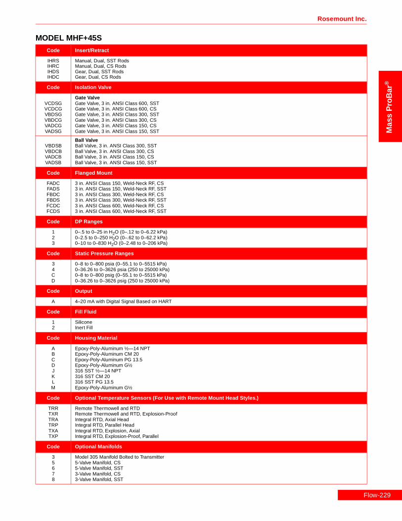
Rosemount Inc.
Mas
sP
roB
ar®
Code Insert/Retract
IHRSIHRCIHDSIHDC
Manual, Dual, SST RodsManual, Dual, CS RodsGear, Dual, SST RodsGear, Dual, CS Rods
Code Isolation Valve
VCDSGVCDCGVBDSGVBDCGVADCGVADSG
Gate ValveGate Valve, 3 in. ANSI Class 600, SSTGate Valve, 3 in. ANSI Class 600, CSGate Valve, 3 in. ANSI Class 300, SSTGate Valve, 3 in. ANSI Class 300, CSGate Valve, 3 in. ANSI Class 150, CSGate Valve, 3 in. ANSI Class 150, SST
VBDSBVBDCBVADCBVADSB
Ball ValveBall Valve, 3 in. ANSI Class 300, SSTBall Valve, 3 in. ANSI Class 300, CSBall Valve, 3 in. ANSI Class 150, CSBall Valve, 3 in. ANSI Class 150, SST
Code Flanged Mount
FADCFADSFBDCFBDSFCDCFCDS
3 in. ANSI Class 150, Weld-Neck RF, CS3 in. ANSI Class 150, Weld-Neck RF, SST3 in. ANSI Class 300, Weld-Neck RF, CS3 in. ANSI Class 300, Weld-Neck RF, SST3 in. ANSI Class 600, Weld-Neck RF, CS3 in. ANSI Class 600, Weld-Neck RF, SST
Code DP Ranges
123
0–.5 to 0–25 in H2O (0–.12 to 0–6.22 kPa)0–2.5 to 0–250 H2O (0–.62 to 0–62.2 kPa)0–10 to 0–830 H2O (0–2.48 to 0–206 kPa)
Code Static Pressure Ranges
34CD
0–8 to 0–800 psia (0–55.1 to 0–5515 kPa)0–36.26 to 0–3626 psia (250 to 25000 kPa)0–8 to 0–800 psig (0–55.1 to 0–5515 kPa)0–36.26 to 0–3626 psig (250 to 25000 kPa)
Code Output
A 4–20 mA with Digital Signal Based on HART
Code Fill Fluid
12
SiliconeInert Fill
Code Housing Material
ABCDJKLM
Epoxy-Poly-Aluminum ½—14 NPTEpoxy-Poly-Aluminum CM 20Epoxy-Poly-Aluminum PG 13.5Epoxy-Poly-Aluminum G½316 SST ½—14 NPT316 SST CM 20316 SST PG 13.5Epoxy-Poly-Aluminum G½
Code Optional Temperature Sensors (For Use with Remote Mount Head Styles.)
TRRTXRTRATRPTXATXP
Remote Thermowell and RTDRemote Thermowell and RTD, Explosion-ProofIntegral RTD, Axial HeadIntegral RTD, Parallel HeadIntegral RTD, Explosion, AxialIntegral RTD, Explosion-Proof, Parallel
Code Optional Manifolds
35678
Model 305 Manifold Bolted to Transmitter5-Valve Manifold, CS5-Valve Manifold, SST3-Valve Manifold, CS3-Valve Manifold, SST
MODEL MHF+45S
Flow-229

Flow-2
Mass ProBar ® Mass Flowmeter
Mass
ProB
ar®
Code Optional Mounting Brackets
K Coplanar Bracket, 2 in., Pipe/Panel, SST Bolts
Code Optional Meters
1 LCD Meter (Rate and Total)
Code Optional Hazardous Location Certificates
ABCDFH
FM Explosion-Proof ApprovalFM Explosion-Proof and Intrinsic Safety ApprovalCSA Explosion-Proof ApprovalCSA Explosion-Proof and Intrinsic Safety ApprovalKEMA/CENELEC Intrinsic Safety ApprovalKEMA/CENELEC Explosion-Proof Approval
Code Optional Calibration
MZOQSUWY
Lab Flow Calibration (Average K) (<10 in.)Special CalibrationLab Flow Calibration (Average K) (12 in.)Lab Flow Calibration (Average K) (14 in. to 16 in.)Lab Flow Calibration (Average K) (18 in. to 20 in.)Lab Flow Calibration (Average K) (24 in.)Lab Flow Calibration (Average K) (30 in.)Lab Flow Calibration (Average K) (36 in.)
Code Optional Quality Assurance
QA1Q21Q23Q29QJ2QM2QT1QT2QT8
Dieterich ProgramANSI B31.1ANSI B31.3NACE MR-0175-91Special Product DrawingASTM Material-Traceable (Sensor Only)Hydrostatic Test EP-4017Dye Penetrant ES-1012Extended Hydro EP-4046
Typical Model Number MHF+45S 240 HATS0 C0000 GV DSA IHRC VADCG FADC 2 3 A 1 A
MODEL MHF+45S
30

Rosemount Inc.
Mas
sP
roB
ar®
MODEL MHF+45HModel Product Description
MHF+45H Mass ProBar® Flowmeter - Flanged Flo-Tap
Code Line Size
100120140160180200240300360420480600720
10 in. (250 mm)12 in. (300 mm)14 in. (350 mm)16 in. (400 mm)18 in. (450 mm)20 in. (500 mm)24 in. (600 mm)30 in. (750 mm)36 in. (900 mm)42 in. (1066 mm)48 in. (1210 mm)60 in. (1520 mm)72 in. (1820 mm)
Code Head Style
HADH0HADHBHADHNHAMH0HAPH0
Direct and Integral Mount Heads - Horizontal LineDirect Mount, with 5-Valve Manifold, Horizontal Line, Hastelloy-CDirect Mount, with 5-Valve Manifold, B31.1, Horizontal Line, Hastelloy-CDirect Mount, with 5-Valve Manifold, NACE, Horizontal Line, Hastelloy-CIntegral, 3-Valve Manifold, Horizontal Line, Hastelloy-CDirect Mount, No Manifold, Horizontal Line, Hastelloy-C
HATH0HATHBHATHDHATHN
Direct and Integral Mount Heads - Horizontal Line with RTDIntegral, 3-Valve Manifold, RTD, Horizontal Line, Hastelloy-CDirect Mount, 5-Valve Manifold, RTD, B31.1, Horizontal Line, Hastelloy-CDirect Mount, with 5-Valve Manifold, RTD, Horizontal Line, Hastelloy-CDirect Mount, 5-Valve Manifold, RTD, NACE, Horizontal Line, Hastelloy-C
HVDH0HVDHBHVDHNHVMH0HVPH0
Direct and Integral Mount Heads - Vertical LineDirect Mount, with 5-Valve Manifold, Vertical Line, Hastelloy-CDirect Mount, 5-Valve Manifold, B31.1, Vertical Line, Hastelloy-CDirect Mount, 5-Valve Manifold, NACE, Vertical Line, Hastelloy-CIntegral, 3-Valve Manifold, Vertical Line, Hastelloy-CDirect Mount, No Manifold, Vertical Line, Hastelloy-C
HVTH0HVTHBHVTHDHVTHN
Direct and Integral Mount Heads - Vertical Line with RTDIntegral, 3-Valve Manifold, RTD, Vertical Line, Hastelloy-CDirect Mount, 5-Valve Manifold, RTD, B31.1, Vertical Line, Hastelloy-CDirect Mount, with 5-Valve Manifold, RTD, Vertical Line, Hastelloy-CDirect Mount, 5-Valve Manifold, RTD, NACE, Vertical Line, Hastelloy-C
HA2H0HA2HSHP2H0
Remote Mount - Horizontal LineAxial, Horizontal Line, ½—14 NPT, Hastelloy-CAxial, Horizontal Line, ½ in. Socket Weld Ports, Hastelloy-CParallel, Horizontal Line, ½—14 NPT, Hastelloy-C
HPVH0HV2H0
Remote Mount - Vertical LineParallel, Vertical Line, ½—14 NPT, Hastelloy-CAxial, Vertical Line, ½—14 NPT, Hastelloy-C
Code Instrument Connections
C0000S0000
Eliminate Instrument Connection Options (For use with Direct and Integral Mount Head Styles)Eliminate Instrument Connection AssemblyEliminate Instrument Connection Assembly (Steam)
CP2C0SP2C0
Needle Valve - CSNeedle Valve, Nipple, ½—14 NPT, CSNeedle Valve, Nipple and Tee, ½—14 NPT, CS
CP2S0SP2S0
Needle Valve - SSTNeedle Valve, Nipple, ½—14 NPT, SSTNeedle Valve, Nipple and Tee, ½—14 NPT, SST
CP2H0Needle Valve - HastelloyNeedle Valve, Nipple, ½—14 NPT, Hastelloy-C
CC2C0SC2C0SV2C0
Gate Valve - CSOutside Stem and Yoke Gate Valve, Nipple, ½—14 NPT, CSOutside Stem and Yoke Gate Valve, Nipple and Tee, ½—14 NPT, CSOutside Stem and Yoke Gate Valve, Vertical Line, Nipple and Tee, ½—14 NPT, CS
CC2S0SC2S0SV2S0
Gate Valve - SSTOutside Stem and Yoke Gate Valve, Nipple, ½—14 NPT, SSTOutside Stem and Yoke Gate Valve, Nipple and Tee, Steam, ½—14 NPT, SSTOutside Stem and Yoke Gate Valve, Vertical Line, Nipple and Tee, ½—14 NPT, SST
Flow-231
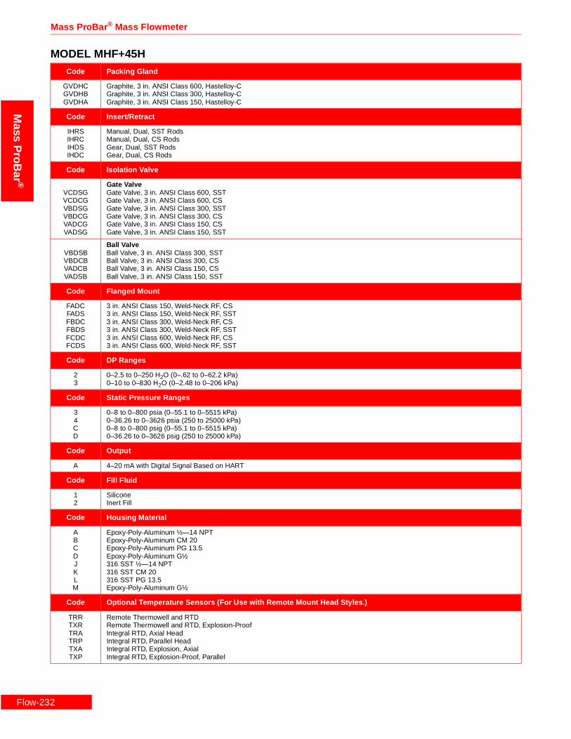
Flow-2
Mass ProBar ® Mass Flowmeter
Mass
ProB
ar®
Code Packing Gland
GVDHCGVDHBGVDHA
Graphite, 3 in. ANSI Class 600, Hastelloy-CGraphite, 3 in. ANSI Class 300, Hastelloy-CGraphite, 3 in. ANSI Class 150, Hastelloy-C
Code Insert/Retract
IHRSIHRCIHDSIHDC
Manual, Dual, SST RodsManual, Dual, CS RodsGear, Dual, SST RodsGear, Dual, CS Rods
Code Isolation Valve
VCDSGVCDCGVBDSGVBDCGVADCGVADSG
Gate ValveGate Valve, 3 in. ANSI Class 600, SSTGate Valve, 3 in. ANSI Class 600, CSGate Valve, 3 in. ANSI Class 300, SSTGate Valve, 3 in. ANSI Class 300, CSGate Valve, 3 in. ANSI Class 150, CSGate Valve, 3 in. ANSI Class 150, SST
VBDSBVBDCBVADCBVADSB
Ball ValveBall Valve, 3 in. ANSI Class 300, SSTBall Valve, 3 in. ANSI Class 300, CSBall Valve, 3 in. ANSI Class 150, CSBall Valve, 3 in. ANSI Class 150, SST
Code Flanged Mount
FADCFADSFBDCFBDSFCDCFCDS
3 in. ANSI Class 150, Weld-Neck RF, CS3 in. ANSI Class 150, Weld-Neck RF, SST3 in. ANSI Class 300, Weld-Neck RF, CS3 in. ANSI Class 300, Weld-Neck RF, SST3 in. ANSI Class 600, Weld-Neck RF, CS3 in. ANSI Class 600, Weld-Neck RF, SST
Code DP Ranges
23
0–2.5 to 0–250 H2O (0–.62 to 0–62.2 kPa)0–10 to 0–830 H2O (0–2.48 to 0–206 kPa)
Code Static Pressure Ranges
34CD
0–8 to 0–800 psia (0–55.1 to 0–5515 kPa)0–36.26 to 0–3626 psia (250 to 25000 kPa)0–8 to 0–800 psig (0–55.1 to 0–5515 kPa)0–36.26 to 0–3626 psig (250 to 25000 kPa)
Code Output
A 4–20 mA with Digital Signal Based on HART
Code Fill Fluid
12
SiliconeInert Fill
Code Housing Material
ABCDJKLM
Epoxy-Poly-Aluminum ½—14 NPTEpoxy-Poly-Aluminum CM 20Epoxy-Poly-Aluminum PG 13.5Epoxy-Poly-Aluminum G½316 SST ½—14 NPT316 SST CM 20316 SST PG 13.5Epoxy-Poly-Aluminum G½
Code Optional Temperature Sensors (For Use with Remote Mount Head Styles.)
TRRTXRTRATRPTXATXP
Remote Thermowell and RTDRemote Thermowell and RTD, Explosion-ProofIntegral RTD, Axial HeadIntegral RTD, Parallel HeadIntegral RTD, Explosion, AxialIntegral RTD, Explosion-Proof, Parallel
MODEL MHF+45H
32

Rosemount Inc.
Mas
sP
roB
ar®
Code Optional Manifolds
35678
Model 305 Manifold Bolted to Transmitter5-Valve Manifold, CS5-Valve Manifold, SST3-Valve Manifold, CS3-Valve Manifold, SST
Code Optional Mounting Brackets
K Coplanar Bracket, 2 in., Pipe/Panel, SST Bolts
Code Optional Meters
1 LCD Meter (Rate and Total)
Code Optional Hazardous Location Certificates
ABCDFH
FM Explosion-Proof ApprovalFM Explosion-Proof and Intrinsic Safety ApprovalCSA Explosion-Proof ApprovalCSA Explosion-Proof and Intrinsic Safety ApprovalKEMA/CENELEC Intrinsic Safety ApprovalKEMA/CENELEC Explosion-Proof Approval
Code Optional Calibration
MZOQSUWY
Lab Flow Calibration (Average K) (<10 in.)Special CalibrationLab Flow Calibration (Average K) (12 in.)Lab Flow Calibration (Average K) (14 in. to 16 in.)Lab Flow Calibration (Average K) (18 in. to 20 in.)Lab Flow Calibration (Average K) (24 in.)Lab Flow Calibration (Average K) (30 in.)Lab Flow Calibration (Average K) (36 in.)
Code Optional Quality Assurance
QA1Q21Q23Q29QJ2QM2QT1QT2QT8
Dieterich ProgramANSI B31.1ANSI B31.3NACE MR-0175-91Special Product DrawingASTM Material-Traceable (Sensor Only)Hydrostatic Test EP-4017Dye Penetrant ES-1012Extended Hydro EP-4046
Typical Model Number MHF+45H 240 HATH0 C0000 GVDHA IHRC VADCG FADC 3 A 1 A
MODEL MHF+45H
Flow-233

Flow-2
Mass ProBar ® Mass Flowmeter
Mass
ProB
ar®
MODEL MHF+45MModel Product Description
MHF+45M Mass ProBar® Flowmeter - Flanged Flo-Tap
Code Line Size
100120140160180200240300360420480600720
10 in. (250 mm)12 in. (300 mm)14 in. (350 mm)16 in. (400 mm)18 in. (450 mm)20 in. (500 mm)24 in. (600 mm)30 in. (750 mm)36 in. (900 mm)42 in. (1066 mm)48 in. (1210 mm)60 in. (1520 mm)72 in. (1820 mm)
Code Head Style
HADM0HADMBHADMNHAMM0HAPM0
Direct and Integral Mount Heads - Horizontal LineDirect Mount, with 5-Valve Manifold, Horizontal Line, MonelDirect Mount, with 5-Valve Manifold, B31.1, Horizontal Line, MonelDirect Mount, with 5-Valve Manifold, NACE, Horizontal Line, MonelIntegral, 3-Valve Manifold, Horizontal Line, MonelDirect Mount, No Manifold, Horizontal Line, Monel
HATM0HATMBHATMDHATMN
Direct and Integral Mount Heads - Horizontal Line with RTDIntegral, 3-Valve Manifold, RTD, Horizontal Line, MonelDirect Mount, 5-Valve Manifold, RTD, B31.1, Horizontal Line, MonelDirect Mount, with 5-Valve Manifold, RTD, Horizontal Line, MonelDirect Mount, 5-Valve Manifold, RTD, NACE, Horizontal Line, Monel
HVDM0HVDMBHVDMNHVMM0HVPM0
Direct and Integral Mount Heads - Vertical LineDirect Mount, with 5-Valve Manifold, Vertical Line, MonelDirect Mount, 5-Valve Manifold, B31.1, Vertical Line, MonelDirect Mount, 5-Valve Manifold, NACE, Vertical Line, MonelIntegral, 3-Valve Manifold, Vertical Line, MonelDirect Mount, No Manifold, Vertical Line, Monel
HVTM0HVTMBHVTMDHVTMN
Direct and Integral Mount Heads - Vertical Line with RTDIntegral, 3-Valve Manifold, RTD, Vertical Line, MonelDirect Mount, 5-Valve Manifold, RTD, B31.1, Vertical Line, MonelDirect Mount, with 5-Valve Manifold, RTD, Vertical Line, MonelDirect Mount, 5-Valve Manifold, RTD, NACE, Vertical Line, Monel
HA2M0HA2MSHP2M0
Remote Mount - Horizontal LineAxial, Horizontal Line, ½—14 NPT, MonelAxial, Horizontal Line, ½ in. Socket Weld Ports, MonelParallel, Horizontal Line, ½—14 NPT, Monel
HPVM0HV2M0HV2MS
Parallel, Vertical Line, ½—14 NPT, MonelAxial, Vertical Line, ½—14 NPT, MonelAxial, Vertical Line, ½ in. Socket Weld Ports, Monel
Code Instrument Connections
C0000S0000
Eliminate Instrument Connection Options (For use with Direct and Integral Mount Head Styles)Eliminate Instrument Connection AssemblyEliminate Instrument Connection Assembly (Steam)
CP2C0SP2C0
Needle Valve - CSNeedle Valve, Nipple, ½—14 NPT, CSNeedle Valve, Nipple and Tee, ½—14 NPT, CS
CP2S0SP2S0
Needle Valve - SSTNeedle Valve, Nipple, ½—14 NPT, SSTNeedle Valve, Nipple and Tee, ½—14 NPT, SST
CP2M0Needle Valve - MonelNeedle Valve, Nipple, ½—14 NPT, Monel
CC2C0SC2C0SV2C0
Gate Valve - CSOutside Stem and Yoke Gate Valve, Nipple, ½—14 NPT, CSOutside Stem and Yoke Gate Valve, Nipple and Tee, ½—14 NPT, CSOutside Stem and Yoke Gate Valve, Vertical Line, Nipple and Tee, ½—14 NPT, CS
CC2S0SC2S0SV2S0
Gate Valve - SSTOutside Stem and Yoke Gate Valve, Nipple, ½—14 NPT, SSTOutside Stem and Yoke Gate Valve, Nipple and Tee, Steam, ½—14 NPT, SSTOutside Stem and Yoke Gate Valve, Vertical Line, Nipple and Tee, ½—14 NPT, SST
34

Rosemount Inc.
Mas
sP
roB
ar®
Code Packing Gland
GVDMCGVDMBGVDMA
Graphite, 3 in. ANSI Class 600, MonelGraphite, 3 in. ANSI Class 300, MonelGraphite, 3 in. ANSI Class 150, Monel
Code Insert/Retract
IHRSIHRCIHDSIHDC
Manual, Dual, SST RodsManual, Dual, CS RodsGear, Dual, SST RodsGear, Dual, CS Rods
Code Isolation Valve
VCDSGVCDCGVBDSGVBDCGVADCGVADSG
Gate ValveGate Valve, 3 in. ANSI Class 600, SSTGate Valve, 3 in. ANSI Class 600, CSGate Valve, 3 in. ANSI Class 300, SSTGate Valve, 3 in. ANSI Class 300, CSGate Valve, 3 in. ANSI Class 150, CSGate Valve, 3 in. ANSI Class 150, SST
VBDSBVBDCBVADCBVADSB
Ball ValveBall Valve, 3 in. ANSI Class 300, SSTBall Valve, 3 in. ANSI Class 300, CSBall Valve, 3 in. ANSI Class 150, CSBall Valve, 3 in. ANSI Class 150, SST
Code Flanged Mount
FADCFADSFBDCFBDSFCDCFCDS
3 in. ANSI Class 150, Weld-Neck RF, CS3 in. ANSI Class 150, Weld-Neck RF, SST3 in. ANSI Class 300, Weld-Neck RF, CS3 in. ANSI Class 300, Weld-Neck RF, SST3 in. ANSI Class 600, Weld-Neck RF, CS3 in. ANSI Class 600, Weld-Neck RF, SST
Code DP Ranges
23
0–2.5 to 0–250 H2O (0–.62 to 0 – 62.2 kPa)0–10 to 0–830 H2O (0–2.48 to 0–206 kPa)
Code Static Pressure Ranges
34CD
0–8 to 0–800 psia (0–55.1 to 0–5515 kPa)0–36.26 to 0–3626 psia (250 to 25000 kPa)0–8 to 0–800 psig (0–55.1 to 0–5515 kPa)0–36.26 to 0–3626 psig (250 to 25000 kPa)
Code Output
A 4–20 mA with Digital Signal Based on HART
Code Fill Fluid
12
SiliconeInert Fill
Code Housing Material
ABCDJKLM
Epoxy-Poly-Aluminum ½—14 NPTEpoxy-Poly-Aluminum CM 20Epoxy-Poly-Aluminum PG 13.5Epoxy-Poly-Aluminum G½316 SST ½—14 NPT316 SST CM 20316 SST PG 13.5Epoxy-Poly-Aluminum G½
Code Optional Temperature Sensors (For Use with Remote Mount Head Styles.)
TRRTXRTRATRPTXATXP
Remote Thermowell and RTDRemote Thermowell and RTD, Explosion-ProofIntegral RTD, Axial HeadIntegral RTD, Parallel HeadIntegral RTD, Explosion, AxialIntegral RTD, Explosion-Proof, Parallel
MODEL MHF+45M
Flow-235

Flow-2
Mass ProBar ® Mass Flowmeter
Mass
ProB
ar®
Code Optional Manifolds
35678
Model 305 Manifold Bolted to Transmitter5-Valve Manifold, CS5-Valve Manifold, SST3-Valve Manifold, CS3-Valve Manifold, SST
Code Optional Mounting Brackets
K Coplanar Bracket, 2 in., Pipe/Panel, SST Bolts
Code Optional Meters
1 LCD Meter (Rate and Total)
Code Optional Hazardous Location Certificates
ABCDFH
FM Explosion-Proof ApprovalFM Explosion-Proof and Intrinsic Safety ApprovalCSA Explosion-Proof ApprovalCSA Explosion-Proof and Intrinsic Safety ApprovalKEMA/CENELEC Intrinsic Safety ApprovalKEMA/CENELEC Explosion-Proof Approval
Code Optional Calibration
MZOQSUWY
Lab Flow Calibration (Average K) (<10 in.)Special CalibrationLab Flow Calibration (Average K) (12 in.)Lab Flow Calibration (Average K) (14 in. to 16 in.)Lab Flow Calibration (Average K) (18 in. to 20 in.)Lab Flow Calibration (Average K) (24 in.)Lab Flow Calibration (Average K) (30 in.)Lab Flow Calibration (Average K) (36 in.)
Code Optional Quality Assurance
QA1Q21Q23Q29QJ2QM2QT1QT2QT8
Dieterich ProgramANSI B31.1ANSI B31.3NACE MR-0175-91Special Product DrawingASTM Material-Traceable (Sensor Only)Hydrostatic Test EP-4017Dye Penetrant ES-1012Extended Hydro EP-4046
Typical Model Number MHF+45M 240 HATM0 C0000 GVDMA IHDC VADCG FADC 2 3 A 1 A
MODEL MHF+45M
36

Rosemount Inc.
Mas
sP
roB
ar®
Flow-237

Mass ProBar ® Mass Flowmeter
Mass
ProB
ar®
Flow-2
38
Rosemount Inc.
Mas
sP
roB
ar®
Flow-239

Mass ProBar ® Mass Flowmeter
Mass
ProB
ar®
Flow-2
40
Rosemount Inc.
Mas
sP
roB
ar®
Flow-241

Mass ProBar ® Mass Flowmeter
Flow-242
Mass
ProB
ar®

Rosemount Inc.
-243
Mas
sP
roB
ar®
Specifications
Flow
FUNCTIONAL SPECIFICATIONS
Service (1)
Liquid, gas, or steam.
Pipe Sizes (2)
½ in. to 72 in. (12 mm to 1800 mm).
Differential Sensor RangesRange 1:0–0.5 in. to 0–25 in. wc
(0–.12 to 0–6.22 kPa).
Range 2:0–2.5 in. to 0–250 in. wc(0–0.62 to 0–62.2kPa).
Range 3:0–10 in. to 0–830 in. wc(0–2.48 to 0–248kPa).
Absolute/Gage Sensor RangesRange 3:0–8 to 0–800 psia
(0–55.16 to 0–5515.8 kPaA).
Range 4:0–36.26 to 0–3,626 psia(0–250 to 0–25000kPaA).
Range C:0–8 to 0–800 psig(0–55.16 to 0–5515.8 kPaG).
Range D:0–36.26 to 0–3,626 psig(0–250 to 0–25000kPaG).
Temperature Sensor Ranges
Integral
-40 °F to 500 °F (-40 °C to 260 °C).
HATSB and HVTSB headstyles for Regular,Flanged, and Flo–Tap flanged models:
-40 °F to 750 °F (-40 °C to 398 °C).
Remote
-40 °F to 850 °F (-40 °C to 454 °C).
Output
Two wire 4-20 mA, user-selectable for DP, AP, PT, or mass flow. Digital HART protocol super imposed on 4–20 mA signal, available to any host that conforms to the HART protocol.
Power Supply
External power supply (or PS120/PS240 option) required. Operates on 11-55VDC with no load.
Load LimitationsLoop resistance is determined by the voltage level of the external power supply, as described below:
Pressure Limits
0 to 1440 psig (100 barg) @ 100 °F (37.8 °C). Contact the factory for higher pressures.
Temperature
Storage
-50 °F to 230 °F (-46 °C to 110 °C).
With Integral Meter
-40 °F to 185 °F (-40 °C to 85 °C).
Process
Integral mount-40 °F to 500 °F (-40 °C to 260 °C).
For HATSB, HVTSB, HADSB, and HVDSB head styles and regular flanged, Flo-Tap models -40 °F to 750 °F (-40 °C to 398 °C).
Remote mount (SST and Monel)-40 °F to 850 °F (-40 °C to 454 °C).
Remote mount (Hastelloy-C)-40 °F to 900 °F (-40 °C to 482 °C).
Remote mount (Hastelloy-C) with remote temperature sensor -40 °F to 1200 °F (-40 °C to 649 °C).
Ambient
-40 °F to 185 °F (-40 °C to 85 °C).
With integral meter
-4 °F to 175 °F (-20 °C to 80 °C).(1) In most cases, the Mass ProBar flowmeter can measure different
fluids with different specific gravity values with no adjustments.High Reynolds Numbers may cause some shifts in overallaccuracy; consult the factory.
(2) Consult factory for line size >72 in.
2000
011.0
4–20 mA dc
55
Load
(Ohm
s)
HART protocol communication requires a loop resistance valuebetween 250–1100 ohms, inclusive.
Max. Loop Resistance = Power Supply Voltage–11.00.022
Power Supply Voltage V dc35
(1) For CSA approval, power supply must not exceed 42.4 V dc.
Operating Region
42.4 V(1)
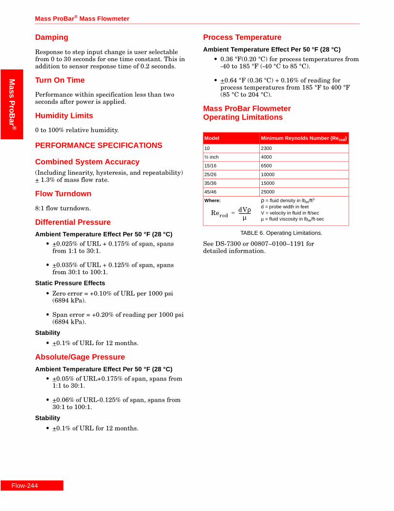
Flow-2
Mass ProBar ® Mass Flowmeter
Mass
ProB
ar®
Damping
Response to step input change is user selectable from 0 to 30 seconds for one time constant. This in addition to sensor response time of 0.2 seconds.
Turn On Time
Performance within specification less than two seconds after power is applied.
Humidity Limits
0 to 100% relative humidity.
PERFORMANCE SPECIFICATIONS
Combined System Accuracy(Including linearity, hysteresis, and repeatability)+ 1.3% of mass flow rate.
Flow Turndown
8:1 flow turndown.
Differential Pressure
Ambient Temperature Effect Per 50 °F (28 °C)
• +0.025% of URL + 0.175% of span, spans from 1:1 to 30:1.
• +0.035% of URL + 0.125% of span, spans from 30:1 to 100:1.
Static Pressure Effects
• Zero error = +0.10% of URL per 1000 psi (6894 kPa).
• Span error = +0.20% of reading per 1000 psi (6894 kPa).
Stability
• +0.1% of URL for 12 months.
Absolute/Gage Pressure
Ambient Temperature Effect Per 50 °F (28 °C)
• +0.05% of URL+0.175% of span, spans from 1:1 to 30:1.
• +0.06% of URL-0.125% of span, spans from 30:1 to 100:1.
Stability
• +0.1% of URL for 12 months.
Process Temperature
Ambient Temperature Effect Per 50 °F (28 °C)
• 0.36 °F(0.20 °C) for process temperatures from-40 to 185 °F (-40 °C to 85 °C).
• +0.64 °F (0.36 °C) + 0.16% of reading for process temperatures from 185 °F to 400 °F (85 °C to 204 °C).
Mass ProBar FlowmeterOperating Limitations
TABLE 6. Operating Limitations.
See DS-7300 or 00807–0100–1191 for detailed information.
Model Minimum Reynolds Number (Re rod )
10 2300
½ inch 4000
15/16 6500
25/26 10000
35/36 15000
45/46 25000
Where: ρ = fluid density in lbm/ft3
d = probe width in feetV = velocity in fluid in ft/secµ = fluid viscosity in lbm/ft-sec
ReroddVρ
µ-----------=
44

Rosemount Inc.
w-245
Mas
sP
roB
ar®
Flo
PHYSICAL SPECIFICATIONS
Electrical Considerations
1/2–14 NPT, PG 13.5, and CM20 conduit. HART interface connections are permanently fixed to the terminal block.
Sensor
316/316L SST.
Hastelloy–C (flanged models, sensors 10, 25/26, and 45/46).
Monel (flanged models, sensors 10, 25/26, and 45/46).
Integral Valve and DirectMount Head Styles (3 and 5 Valve)
Material
316 SST, Hastelloy–C and Monel options.
O–Rings
Teflon® (Grafoil above 500 °F [260 °C]).
Bolts
316 SST.
Flange, Isolation Valves
316L SST. Flange pressure limits are per ANSI B16.5 for 316 SST and material per SA 182. Flange face finish ANSI B16.5, 125 to 250 RMS.
Packing Gland Assembly
Packing Gland316 SST.
Packing
Graphite AFP–127.
Flange Mounting Hardware
Includes nuts, bolts, and gasket
316 SST or CS.
Temperature Options
Integral RTD
• 100 Ω Platinum RTD.
Remote
• 100 Ω Platinum RTD.
• Spring loaded with ½ —14 NPT nipple and union.
• Thermowell: ½ in. × ½.—14 NPT, 316 SST with ½ in. CS weld couplet, u = 2½ in.
Electronics
SST Models• Vent valve and process: 316 SST.• Flanges: 316 SST.• Process isolating diaphragms: 316L SST.• O–rings: Glass-filled TFE.
Hastelloy and Monel models• Vent valves and process flanges: Hastelloy–C.• Process isolating diaphragms: Hastelloy–C.• O–rings: Glass-filled TFE.
Hazardous Locations CertificationsFactory Mutual (FM) ApprovalsA Explosion Proof for Class I, Division 1,
Groups B, C, and D. Dust-Ignition Proof for Class II, Division 1, Groups E, F, and G. Dust-Ignition Proof for Class III, Division 1. NEMA 4X. Factory Sealed. Install per Rosemount drawing 03095-1025.
B Combination of Approval Code A and the following: Intrinsically Safe for use in Class I, Division 1, Groups A, B, C and D; Class II, Division 2, Groups E, F, and G; Intrinsically safe for Class III, Division 1. Nonincendive for Class I, Division 2, Groups A, B, C, and D. Temperature Code T4. Install per Rosemount drawing 03095-1020.
Canadian Standards Association (CSA)C Explosion Proof for Class I, Division 1, Groups C, and D.
Dust-Ignition Proof for Class II, Division 1, Groups E,F, and G. Dust-Ignition Proof for Class III, Division 1.Suitable for Class I, Division 2, Groups A, B, C, and D. CSA Enclosure-Type 4X. Factory-sealed. Rosemount Drawings 03095-1024.
D Combination of Approval Code C and the following:Intrinsically safe for use in Class I, Division 1, GroupsA, B, C and D when connected in accordance withRosemount Drawings 03095-1021.Temperature Code T3C.
KEMA/CENELECH Explosion Proof.
EEx d IIC T5 (Tamb = 70 C).EEx d IIC T6 (Tamb = 40 C).Enclosure Type: IP65.
F Intrinsically safe. EEx ia IIC T5 (Tamb = -45 to +40 C).EEx ia IIC T4 (Tamb = -45 to +70 C).Ui = 30V dcIi = 200 mAPi = 1.0 WCi = 0.012 µFLi = 0

00813-0100-4762 Rev. DA
¢00813-0100-4762+¤
Dieterich Standard Inc.5601 North 71st StreetBoulder, CO 80301Tel (303) 530-9600Fax (303) 530-7064
© 1998 Rosemount Inc.http://www.rosemount.com
PR
INTED
INU.S. A.
Fisher-RosemountSingapore Pte Ltd.1 Pandan CrescentSingapore 128461Tel (65) 777-8211Fax (65) 770-8007Tlx RS 61117 FRSPL
Fisher-Rosemount LimitedHeath Place Bognor RegisWest Sussex PO22 9SHEnglandTel 44 (1243) 863 121Fax 44 (1243) 867 5541
Rosemount Inc.8200 Market BoulevardChanhassen, MN 55317 USATel 1-800-999-9307Telex 4310012Fax (612) 949-7001
Mass ProBar ® Mass Flowmeter
Flow-246
Mass
ProB
ar®
May be protected by one or more of the following U.S. Patent Nos.4,559,836; 4,717,159, and variousforeign patents. Other foreign patents issued and pending.
Rosemount and the Rosemount logotype are registered trademarks of Rosemount Inc.Coplanar, MV, and Multivariable are trademarks of Rosemount Inc.PlantWeb is a mark of the Fisher-Rosemount group of companies.Mass ProBar, ProBar, and Annubar are registered trademarks of Dieterich Standard Inc.HART is a registered trademark of the HART Communications Foundation.Monel is a registered trademark of International Nickel Co.Teflon is a registered trademark of E. I. du Pont de Nemours & Co.Hastelloy C and Hastelloy C-276 are registered trademarks of Cabot Corp.Windows is a trademark of Microsoft Corp.
Cover Photo: 1295-001AB