master catalog switches - allied electronics cost laser marking on piece parts ... pc thru hole left...
TRANSCRIPT

M A S T E R C A T A L O G
Switches

QUALITY IN A
Global Marketplace
Cherry’s principal productioncapabilities include:
Complex, multi-station die design andbuild capabilities, utilizing the latest in-diesensing and slug detection techniques
In-die welding and contact insertingcapabilities, which eliminate costly secondary operations.
Precision metal stamping, using presses ranging from 40 to 100 tons and press speeds from 200 to 1000strokes per minute
Low cost laser marking on piece partsand finished assemblies
Robotic switch assembly and testing toensure the highest quality standards
We are committed to meeting or exceedingthe highest standards for quality assurance— not only in our products, but also in ourprocesses. Our primary objective is toachieve zero defects in every aspect of ouractivites. As part of our pre-emptive strategy,the prevention of defects always takesprecedent over their detection.
The quality assurance processes atCherry’s manufacturing facilities in theUnited States, Europe and Asia have been certified under ISO 9001and ISO 14001 Environmental.
Cherry has been the leader in switch innovation since its
inception in 1953. To better serve our customers in today’s
global marketplace, we now maintain offices and manufacturing
facilities in eleven locations worldwide — each with its own
engineering and sales staff.
Cherry Locations Worldwide
The Cherry CorporationPleasant Prairie, Wisconsin, USA
Cherry Mikroschalter GmbHAuerbach, Germany
Cherry Electrical Products DivisionPleasant Prairie, Wisconsin, USA
Cherasia LimitedHong Kong
Cherry Electrical Products Ltd.Harpenden, England
Cherry SROKlasterec, Czech Republic
Cherry de Mexico, S.A. de C.V.Juarez, Mexico
Cherry ZhuhaiZhuhai, China
Cherry SARLParis, France
Cherry Australia Pty. Ltd.Melbourne, Australia
TVS Cherry Private LimitedMadurai, India

3
TABLE OF
ContentsIntroductionSelection Guide 4–5
Snap Action SwitchesSubminiatureDH Series 6–7DG Series 8–9DR Series 10–11DB Series 12–15E61–E64 Series 16–18
Subminiature — SealedDC Series 19–21DK Series 22–23DCJK Series 24–25DJ Series 26–27E72–E73 Series 28–29
MiniatureD4 Series 30–33D3 Series 34–36E21–E36 Series 37–39E51–E53 Series 40–41K Series 42–43
General PurposeGP Series 44–47E13–E20 Series 48–50
Panel Mount SwitchesPanel Mount/Line InterruptE65–E/F79 Series 51–53F80 Series 54–55
Rocker SwitchesCR Series 56–57SR Series 58–59LR Series 60–61TR Series 62–63WR Series 64–65GR Series 66–67RR Series 68–69PR Series 70–71FR Series 72–73SR Round Series 74–75
Other SwitchesKeyswitches, etc. 76–77
Technical SectionGlossary/Tech Info 78
4
Bu
tto
n O
nly
Wir
e F
orm
Fla
t L
ever
Sim
ula
ted
Ro
ller
Ro
ller
Lea
d W
ires
DIN
Qu
ick
Co
nn
ect
So
lder
Ter
min
als
PC
Scr
ew
Lin
e In
terr
up
t
NC
NO
DP
DT
SP
DT
SP
ST
Mo
un
tin
gC
ente
rlin
e S
pac
ing
Inch
es (m
m)
PC
Mo
un
t
Th
read
ed F
erru
le
Mo
un
tin
g H
ole
s
Sn
ap-I
n
VD
E A
pp
rove
d
Deg
ree
of
Pro
tect
ion
Max
. Tem
per
atu
re (°
C)
Max.CurrentRating
SeriesName
Switch Type(Size)
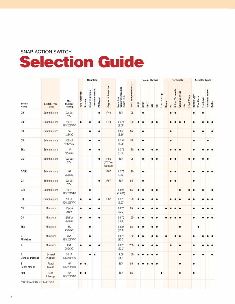
SNAP-ACTION SWITCH
Selection Guide
DR Subminiature 2A DC* IP40 N/A 105
12V
DB Subminiature 10.1A IP40 0.374 120
125/250VAC (9.50)
DG Subminiature 3A 0.256 85
125VAC (6.50)
DH Subminiature 500mA 0.157 70
@30VDC (3.99)
E6x Subminiature 13A 0.375 130
125VAC (9.53)
DK Subminiature 2A DC* IP65 N/A 105
12V (IP67 onrequest)
DCJK Subminiature 10A IP67 0.375 120
250VAC (9.53)
DJ Subminiature 2A DC* IP67 N/A 85
12V
E7x Subminiature 10.1A 0.625 85
125/250VAC (15.88)
DC Subminiature 10.1A IP67 0.375 120
125/250VAC (9.53)
D3 Miniature 16(4)A 0.875 85
250V (22.2)
D4 Miniature 21(8)A 0.875 150
250VAC (22.2)
E5x Miniature 6A 0.937 85
250VAC (23.8)
E Miniature 25A 0.875 150
Miniature 125/250VAC (22.2)
K Miniature 25A 0.875 200
250VAC (22.2)
E General 30.1A 1.00 150
General Purpose Purpose 125/250VAC (25.4)
E Panel 16A N/A 85
Panel Mount Mount 125/250VAC
F80 Line 16A N/A 85
Interrupt 125/250VAC
*DR, DK and DJ Series: 2A@12VDC
Mounting Poles / Throws Actuator TypesTerminals

5
Terminals Actuator Types
Fla
t
2 C
olo
r
Cu
rved
Qu
ick
Co
nn
ect
0.18
7″(4
.8m
m)
PC
th
ru H
ole
Lef
t A
ng
le
PC
th
ru H
ole
Str
aig
ht
So
lder
Tab
So
lder
2.0
9″x
1.06
″(5
2.09
mm
x 2
6.92
mm
)
PC
th
ru H
ole
Rig
ht
An
gle
Qu
ick
Co
nn
ect
0.24
8″(6
.3m
m)
Wir
e L
ead
s
Ratings
Am
p R
atin
g@12
5VA
C
Am
p R
atin
g@25
0VA
C
On
–Off
–On
On
–(O
n)
(On
)–O
ff
On
–On
On
–Off
SeriesName
Panel Cut-Out Approx
Inches (mm)
PANEL MOUNT ROCKER SWITCH
Selection Guide
CR 1.13 (28.8) 20A 16A IP42
x variable
LR 0.760 x 0.508 10A 8A
(19.3 x 12.9)
SR 0.760 x 0.508 10A 6A
(19.3 x 12.9)
TR 1.20 x 0.433 16A 16A
(30.4 x 11.0)
WR 1.19 x 0.867 16A 16A
(30.2 x 22.0)
RR Round 10A 8A
0.787 (20.0) dia.
GR 1.13 x 0.535 15A 10A
PR 0.539 x 0.362 6A 3A
(13.7 x 9.2)
FR 0.760 x 0.862 12A 12A
(19.35 x 21.90)
SR Round 0.787 x 0.827 20A 12A
(20.0 x 21.0)
Circuitry Approvals
SP
ST
SP
DT
DP
ST
DP
DT
(On
)–O
ff–(
On
)
On
–Off
-(O
n)
Lig
hte
d A
vaila
ble
Deg
ree
of
Pro
tect
ion
Ava
ilab
le
UL
VD
E
CS
A

SUBMINIATURE
DHSeries
Gold-platedsilver alloy contacts
Stainless steel
Common terminal
NC terminal NO terminal
Thermoplasticpolyester base
Features
Ultraminiature dimensions, just 0.323″ x 0.106″ x 0.244″(8.2mm x 2.7mm x 6.2mm)
Specially designed for low switchingcurrents and voltages
Available with or without integratedauxiliary actuator
Can be fitted to circuit boards in upright position or horizontally with formed terminals
SpecificationsElectrical
Temperature Rating: -25°C to +70°CFlammability Rating: UL94V-O
Materials
Base: PPSButton: PBTCover: PBTAuxiliary Actuator: Stainless SteelTerminals: Silver-Plated BrassContacts: Silver-Plated Brass (DH3)
Gold-Plated Brass (DH4)PBT = Polybutyleneterephthalate • PPS = Polyphenylene Sulphide
Electrical RatingsSwitch Series Electrical Rating
DH3 50 to 300mA@30VDCDH4 5 to 50mA@30VDC

7
0.323(8.2)
0.098(2.5)
0.023±.002(0.6±0.05)
0.10
6(2
.7)
Reference Line
0.20
7(5
.25)
Ope
ratin
g P
oint
Res
t Pos
ition
Ø0.063 +0.040
(Ø1.6 +0.1)
0.047±0.004(1.2±0.1)
0.098(2.5)
0.098(2.5)
0.157±0.004(4.0±0.1)
0.06
3±0.
004
(1.6
±0.
1) 0.11
8(3
.0)
0.19
6(4
.97)
0.18
1(4
.6)
0.00
6(0
.15)
0.211(5.35)0.252(6.4)
DH 3 C B1 AA
Series/Prefix
Code Current Rating
3 50 to 300mA@30VDC4 5 to 50mA@30VDC
Code Contact Configuration
C SPDTCode Terminal Type inches (mm) Terminal Configuration
B1 0.051 x 0.122 x 0.020 (1.3 x 3.1 x 0.5)Solder, Straight
C4 0.025 x 0.122 x 0.020 (0.6 x 3.1 x 0.5)PCB, Straight
C5 0.025 x 0.122 x 0.020 (0.6 x 3.1 x 0.5)PCB, RH Side
C6 0.025 x 0.122 x 0.020 (0.6 x 3.1 x 0.5)PCB, LH Side
Code Actuator Type
AA ButtonLA Simulated Roller
Ordering Information
Dimensions inches (mm)
Specifications subject to change without notice.
0.157(4.0)
Tolerance: ±0.002 (±0.05)(TOP VIEW)
(2)–ø 0.070(2)–(ø1.80)
ø0.039(ø1.00)
0.13
4(3
.4)
0.098(2.5)
0.098(2.5)
PCB Layout inches (mm)
MountingRecommended mounting screw: M1.6. Rec-ommended torque: 9.81 cN•M (1.0 kgf•cm). Recommended use of a flat washer and a spring washer for locking.
Actuator SpecificationsMaximum Maximum Operating Minimum Max. MovementOperating Pre-Travel Point Over-Travel Differential
Actuator Switch Force inches inches inches inchesType Type (gms.) (mm) (mm) (mm) (mm)AA 90 0.008 0.220±0.006 0.004 0.003
(0.2) (5.6±0.15) (0.1) (0.07)LA 50 0.051 0.264±0.020 0.012 0.024
(1.3) (6.7±0.5) (0.3) (0.6)

SUBMINIATURE
DGSeries
Silver-nickel or gold contacts
PBTactuating button
PBT cover
PPHS base
Silver-plated copper-zincterminals
NC terminal NO terminal Common terminal
Features
Small dimensions, just 0.504″ x 0.228″ x 0.256″(12.8mm x 5.8mm x 6.5mm)
Depending on model, contact rating issuitable for low switched currents andvoltages for light-current applicationswith loads of up to 3 amps 125VAC
Available with or without auxiliary actuator
Can be fitted to circuit boards in uprightposition or horizontally with terminals onleft or right
Mechanical life: min. 1 x 10⁶ operations(depending on model)
SpecificationsElectrical
Temperature Rating: -25°C to +85°CFlammability Rating: UL9V-O
Materials
Base: PPHSCover: PBTActuator: PBTAuxiliary Actuator: Stainless SteelTerminals: Silver-Plated BrassContacts: Silver Alloy (DG1, DG4)
Gold Flash, Gold (DG2)PBT = Polybutyleneterephthalate • PPHS = Polyphenylene sulphide
Electrical RatingsElectrical Life at Rated Load
Switch According to ULSeries EN61058 Rating UL1054 Rating (Min. Operations)
DG1 N/A 3A, 125VAC; 2A, 30VDC 6,000DG2 N/A 0.05A, 30VDC 6,000DG4 N/A 1A, 125VAC; 1A, 30VDC 6,000
9
0.19
7(5
.0)
0.05
9(1
.5)
0.07
9(2
.0)
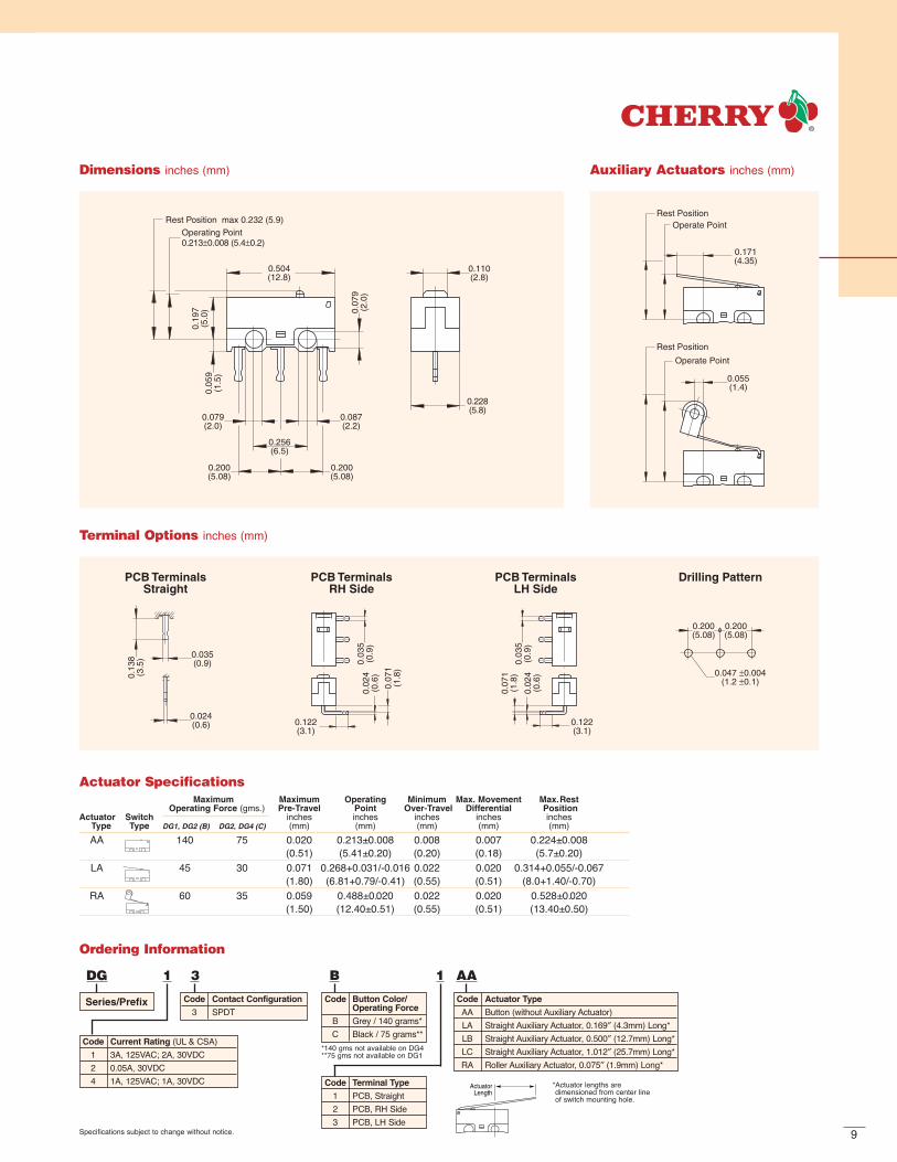
0.504(12.8)
Operating Point 0.213±0.008 (5.4±0.2)
Rest Position max 0.232 (5.9)
0.079(2.0)
0.087(2.2)
0.256(6.5)
0.200(5.08)
0.200(5.08)
0.110(2.8)
0.228(5.8)
Dimensions inches (mm)
PCB TerminalsStraight
PCB TerminalsRH Side
PCB TerminalsLH Side
Drilling Pattern
0.035(0.9)
0.13
8(3
.5)
0.024(0.6)
0.03
5(0
.9)
0.03
5(0
.9)
0.07
1(1
.8)
0.07
1(1
.8)
0.02
4(0
.6)
0.02
4(0
.6)
0.122(3.1)
0.122(3.1)
0.200(5.08)
0.200(5.08)
0.047 ±0.004(1.2 ±0.1)
Terminal Options inches (mm)
Rest Position
0.171(4.35)
Operate Point
Rest Position
Operate Point
0.055(1.4)
Auxiliary Actuators inches (mm)
Code Button Color/Operating Force
B Grey / 140 grams*C Black / 75 grams**
DG 1 3 B 1 AA
Series/Prefix
Code Current Rating (UL & CSA)1 3A, 125VAC; 2A, 30VDC2 0.05A, 30VDC4 1A, 125VAC; 1A, 30VDC
Code Contact Configuration
3 SPDTCode Actuator Type
AA Button (without Auxiliary Actuator)LA Straight Auxiliary Actuator, 0.169″ (4.3mm) Long*LB Straight Auxiliary Actuator, 0.500″ (12.7mm) Long*LC Straight Auxiliary Actuator, 1.012″ (25.7mm) Long*RA Roller Auxiliary Actuator, 0.075″ (1.9mm) Long*
Ordering Information
Specifications subject to change without notice.
*140 gms not available on DG4**75 gms not available on DG1
*Actuator lengths are dimensioned from center line of switch mounting hole.
Code Terminal Type
1 PCB, Straight2 PCB, RH Side3 PCB, LH Side
ActuatorLength
Actuator SpecificationsMaximum Maximum Operating Minimum Max. Movement Max.Rest
Operating Force (gms.) Pre-Travel Point Over-Travel Differential PositionActuator Switch inches inches inches inches inches
Type Type DG1, DG2 (B) DG2, DG4 (C) (mm) (mm) (mm) (mm) (mm)AA 140 75 0.020 0.213±0.008 0.008 0.007 0.224±0.008
(0.51) (5.41±0.20) (0.20) (0.18) (5.7±0.20)LA 45 30 0.071 0.268+0.031/-0.016 0.022 0.020 0.314+0.055/-0.067
(1.80) (6.81+0.79/-0.41) (0.55) (0.51) (8.0+1.40/-0.70)RA 60 35 0.059 0.488±0.020 0.022 0.020 0.528±0.020
(1.50) (12.40±0.51) (0.55) (0.51) (13.40±0.50)

SUBMINIATURE
DRSeriesStainless steel spring
Gold-platedberyllium copper blade
Stainless steelinternal actuator
POM actuating button
PBT base and cover
NO terminalNC terminal
Gold crosspoint contacts
Silver-platedcopper zinc terminals
Common terminal
Features
Switch with mushroom or pan-head actuator for a wide variety of control applications
Protection against dust complying with IP40
Models available for operatingtemperatures up to 105°C
Rated for 5mA@12VDC or 2A@12VDC
Auxiliary actuator on request
High contact stability thanks to gold alloy crosspoint contacts
Mechanical life: min. 1 x 10⁶ operations
Various options available for connecting
SpecificationsElectrical
Temperature Rating: -40°C to +85°CFlammability Rating: N/A
Materials
Housing: PBTActuator: POM (+85°C) Auxiliary Actuator: Stainless SteelInternal Actuator: Stainless SteelSpring: Stainless SteelTerminals: Silver-Plated Copper-ZincContacts: Gold CrosspointMoving Blade: Gold-Plated Beryllium CopperPBT = Polybutyleneterephthalate • POM = Polyacetal
11
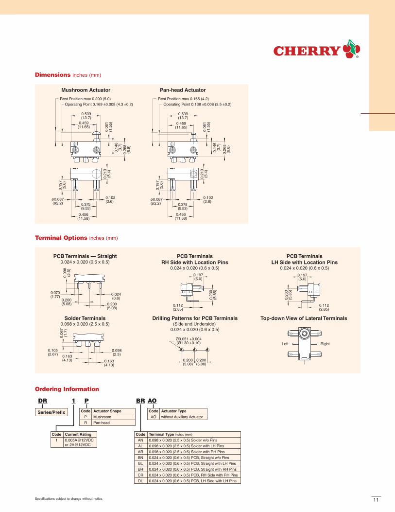
0.539(13.7)
0.459(11.65)
0.539(13.7)
0.459(11.65)
0.375(9.53)
0.456(11.58)
ø0.087(ø2.2)
0.102 (2.6)
0.102 (2.6)
Mushroom Actuator Pan-head Actuator
0.26
8(6
.8)
0.26
8(6
.8)
0.06
1(1
.55)
0.06
1(1
.55)
0.19
7(5
.0)
0.19
7(5
.0)
ø0.087(ø2.2) 0.375
(9.53)
0.456(11.58)
Rest Position max 0.200 (5.0)Operating Point 0.169 ±0.008 (4.3 ±0.2)
Rest Position max 0.165 (4.2)Operating Point 0.138 ±0.008 (3.5 ±0.2)
0.14
6(3
.7)
0.14
6(3
.7)
0.21
3(5
.4)
0.21
3(5
.4)
Dimensions inches (mm)
Left Right
0.200(5.08)
0.200(5.08)
Ø0.051 +0.004(Ø1.30 +0.10)
0.105(2.67) 0.163
(4.13) 0.163(4.13)
0.098(2.5)
0.06
7(1
.7)
0.09
8(2
.5)
0.070(1.77)
0.200(5.08) 0.200
(5.08)
0.024(0.6)
0.112(2.85)
0.197(5.0)
0.23
0(5
.85)
0.112(2.85)
0.197(5.0)
0.23
0(5
.85)
Solder Terminals0.098 x 0.020 (2.5 x 0.5)
Top-down View of Lateral Terminals Drilling Patterns for PCB Terminals(Side and Underside)
0.024 x 0.020 (0.6 x 0.5)
PCB Terminals — Straight0.024 x 0.020 (0.6 x 0.5)
PCB TerminalsRH Side with Location Pins
0.024 x 0.020 (0.6 x 0.5)
PCB TerminalsLH Side with Location Pins
0.024 x 0.020 (0.6 x 0.5)
Terminal Options inches (mm)
Specifications subject to change without notice.
DR 1 P BR AO
Series/Prefix
Code Current Rating
1 0.005A@12VDCor 2A@12VDC
Code Terminal Type inches (mm)
AN 0.098 x 0.020 (2.5 x 0.5) Solder w/o PinsAL 0.098 x 0.020 (2.5 x 0.5) Solder with LH PinsAR 0.098 x 0.020 (2.5 x 0.5) Solder with RH PinsBN 0.024 x 0.020 (0.6 x 0.5) PCB, Straight w/o PinsBL 0.024 x 0.020 (0.6 x 0.5) PCB, Straight with LH PinsBR 0.024 x 0.020 (0.6 x 0.5) PCB, Straight with RH PinsCR 0.024 x 0.020 (0.6 x 0.5) PCB, RH Side with RH PinsDL 0.024 x 0.020 (0.6 x 0.5) PCB, LH Side with LH Pins
Code Actuator Shape
P MushroomR Pan-head
Code Actuator Type
AO without Auxiliary Actuator
Ordering Information

SUBMINIATURE
DBSeriesPBT cover POM
actuating button
Stainless steelspring
PET base
Silver-alloygold crosspoint
contacts
Silver-platedcopper-zincterminals
NC terminal
NO terminal
Common terminal
Features
High-precision switch with high repeat accuracy
Models available for operatingtemperatures up to 120°C
Rated for currents up to 10 amp at 250VAC
Range of auxiliary actuators available (can also be retrofitted); two mounting positions
Variety of contact materials available to suit your application
Mechanical life: up to 15 x 106 operations
Wide variety of terminal types available
Numerous approvals
SpecificationsElectrical
Temperature Rating: -40°C to +85°C / +120°CFlammability Rating: UL94V-O (PBT, PET)
UL94HB (POM)
Materials
Base: PETCover: PBTActuator: PBT, POMAuxiliary Actuator: Stainless Steel or PlasticTerminals: Silver-Plated Copper-ZincContacts: Silver Alloy
Gold CrosspointPBT = Polybutyleneterephthalate • PET = Polyethyleneterephthalate • POM = Polyacetal
Electrical RatingsElectrical Life at Rated Load
Switch According to EN According to ULSeries EN61058 Rating UL1054 Rating (Min. Operations) (Min. Operations)
DB1 6A, 250V~ 5A, 125/250VAC 10,000 6,000DB2 10(1.5)A, 250V~ 10.1A, 125/250VAC; 1/4HP, 125VAC 10,000 6,000DB3 0.1A, 250V~ 0.1A,125/250VAC 50,000 6,000DB5* 1A, 250V~ 1A, 125/250VAC 50,000 6,000DB6* 6A, 250V~ 5A, 125/250VAC 50,000 6,000DB7* 10(1.5A), 400V~ 10.1A, 125/250VAC; 1/4HP, 125VAC 50,000 6,000*85°C

13
Rest position 0.366 (9.3 max.)
0.098(2.5)
Operating point 0.331± 0.012 (8.4±0.3)
0.28
7(7
.3)
0.27
2(6
.9)
0.08
7(2
.2)
0.787 max.(20.0)
0.295(7.5)
ø 0.087(2.2)
0.295(7.5)
0.295(7.5)
0.107(2.73)
0.374(9.5)
0.205(5.2)
0.09
3(2
.35)
0.26
2(6
.65)
0.256(6.5)
Auxiliary Actuator inches (mm)Dimensions inches (mm)
0.13
8(3
.5)
0.13
8(3
.5)
0.22
0(5
.6)
0.11
4(2
.9)ø0.197
(5.0)
R 2
»L«
»L«
»L« ±0.031(0.8)
»L« ±0.031(0.8)
»L« ±0.031(0.8)
»L« ±0.031(0.8)
ø0.189(4.8)
≤0.
217
(5.5
)
0.13
0(3
.3)
0.13
8(3
.5)
R 0.098(2.5)
High Ratio (HR)Standard Ratio (SR)
±0.031(0.8)
0.13
8(3
.5)
OperatingPoint
RestPosition
Straight
Straight – Plastic
Roller
Roller – Plastic
Simulated Roller
Simulated Roller – Plastic
±0.031(0.8)
Contact Ratings at Direct Voltage
Switched Current Inductive LoadSwitching Resistive Load L/R=3ms
Voltage DB1 DB2 DB1 DB2
12V 6A 10A 6A 10A24V 3A 5A 2A 4A60V 1A 1A 0.5A 0.5A110V 0.5A 0.5A 0.2A 0.2A220V 0.25A 0.25A 0.1A 0.1A
QC Terminals0.110 x 0.020 (2.8 x 0.5)
Solder Terminals – Short PCB Terminals – Straight0.051 x 0.020 (1.3 x 0.5)
PCB Terminals – Straight0.024 x 0.020 (0.6 x 0.5)
PCB TerminalsRH Side w/o Location Pins
0.024 x 0.020 (0.6 x 0.5)
PCB TerminalsRH Side with Location Pins
0.024 x 0.020 (0.6 x 0.5)
PCB TerminalsLH Side with Location Pins
0.024 x 0.020 (0.6 x 0.5)
PCB TerminalsLH Side w/o Location Pins
0.024 x 0.020 (0.6 x 0.5)
Top-down View of Lateral Terminals
Drilling Patterns for PCB Terminals
0.051 x 0.020 (1.3 x 0.5)
0.295(7.5)
0.295(7.5)
Ø0.063 (1.6)
Drilling Patterns for PCB Terminals
(Straight/Lateralw/o Location Pins)
0.024 x 0.020 (0.6 x 0.5)
0.295(7.5)
0.295(7.5)
Ø0.051 (1.3)
Drilling Patterns for PCB Terminals
(Lateral with Location Pins)0.024 x 0.020 (0.6 x 0.5)
0.295(7.5)
0.295(7.5)
0.107(2.73)
0.200(5.08)
Ø0.051(1.3)
Ø0.067(1.7)
0.374 (9.5)
0.071(1.8)
0.110(2.8)
0.12
6(3
.2)
0.12
2(3
.1)
0.12
2(3
.1)
0.051(1.3)0.110
(2.8)
0.047(1.2)
0.28
7(7
.3)
0.122(3.1)
0.122(3.1)
0.024(0.6)
0.138(3.5)0.266
(6.75)
0.200(5.08)
0.138(3.5) 0.266
(6.75)
0.200(5.08)
0.110(2.8)
0.138(3.5)0.266
(6.75)
0.200(5.08)
0.110(2.8)
0.138(3.5) 0.266
(6.75)
0.200(5.08)
Left Right
Terminal Options inches (mm)

14
Actuator Specifications — Standard RatioMaximum Maximum Operating Minimum Max. Movement Max. Rest Actuation
Actuator Switch Operating Force Pre-Travel Point Over-Travel Differential Position Length Code Type (gms.) inches (mm) inches (mm) inches (mm) inches (mm) inches (mm) inches (mm)AA DB5 70 0.039 (1.0) 0.331±0.012 (8.4±0.3) 0.024 (0.6) 0.004 (0.10) 0.366 (9.3) —
DB1/3 150 0.039 (1.0) 0.331±0.012 (8.4±0.3) 0.024 (0.6) 0.004 (0.10) 0.366 (9.3) —DB6 150 0.039 (1.0) 0.331±0.012 (8.4±0.3) 0.024 (0.6) 0.006 (0.15) 0.366 (9.3) —DB2 250 0.039 (1.0) 0.331±0.012 (8.4±0.3) 0.024 (0.6) 0.004 (0.10) 0.366 (9.3) —DB7 280 0.039 (1.0) 0.331±0.012 (8.4±0.3) 0.024 (0.6) 0.006 (0.15) 0.366 (9.3) —
BA DB5 70 0.039 (1.0) 0.331±0.012 (8.4±0.3) 0.024 (0.6) 0.004 (0.10) 0.366 (9.3) —DB1/3 150 0.039 (1.0) 0.331±0.012 (8.4±0.3) 0.024 (0.6) 0.004 (0.10) 0.366 (9.3) —DB6 250 0.039 (1.0) 0.331±0.012 (8.4±0.3) 0.024 (0.6) 0.006 (0.15) 0.366 (9.3) —DB2 250 0.039 (1.0) 0.331±0.012 (8.4±0.3) 0.024 (0.6) 0.004 (0.10) 0.366 (9.3) —DB7 280 0.039 (1.0) 0.331±0.012 (8.4±0.3) 0.024 (0.6) 0.006 (0.15) 0.366 (9.3) —
Auxiliary actuator, rear-mounted (RM)LB DB5 30 0.157 (4.0) 0.421±0.051 (10.7±1.3) 0.079 (2.0) 0.020 (0.5) 0.551 (14.0) —
DB1/3 60 0.157 (4.0) 0.421±0.051 (10.7±1.3) 0.079 (2.0) 0.020 (0.5) 0.551 (14.0) —DB6 60 0.157 (4.0) 0.421±0.051 (10.7±1.3) 0.079 (2.0) 0.030 (0.75) 0.551 (14.0) 0.189 (4.8)DB2 100 0.177 (4.5) 0.421±0.063 (10.7±1.6) 0.059 (1.5) 0.028 (0.70) 0.551 (14.0) —DB7 115 0.177 (4.5) 0.421±0.063 (10.7±1.6) 0.059 (1.5) 0.030 (0.75) 0.551 (14.0) —
LC DB5 25 0.177 (4.5) 0.437±0.059 (11.1±1.5) 0.079 (2.0) 0.024 (0.6) 0.591 (15.0) —DB1/3 50 0.177 (4.5) 0.437±0.059 (11.1±1.5) 0.079 (2.0) 0.024 (0.6) 0.591 (15.0) —DB6 50 0.177 (4.5) 0.437±0.059 (11.1±1.5) 0.079 (2.0) 0.047 (1.2) 0.591 (15.0) 0.276 (7.0)DB2 85 0.197 (5.0) 0.437±0.071 (11.1±1.8) 0.059 (1.5) 0.039 (1.0) 0.591 (15.0) —DB7 100 0.197 (5.0) 0.437±0.071 (11.1±1.8) 0.059 (1.5) 0.047 (1.2) 0.591 (15.0) —
LD DB5 9 0.591 (15.0) 0.512±0.138 (13.0±3.5) 0.157 (4.0) 0.177 (4.5) 1.063 (27.0) —DB1/3 18 0.591 (15.0) 0.512±0.138 (13.0±3.5) 0.157 (4.0) 0.177 (4.5) 1.063 (27.0) 1.654 (42.0)DB6 18 0.591 (15.0) 0.512±0.138 (13.0±3.5) 0.157 (4.0) 0.268 (6.8) 1.063 (27.0) —DB2/7 — — — — — — on request
SB DB5 30 0.157 (4.0) 0.630±0.051 (16.0±1.3) 0.079 (2.0) 0.020 (0.5) 0.748 (19.0) —DB1/3 65 0.157 (4.0) 0.630±0.051 (16.0±1.3) 0.079 (2.0) 0.020 (0.5) 0.748 (19.0) —DB6 65 0.157 (4.0) 0.630±0.051 (16.0±1.3) 0.079 (2.0) 0.043 (1.1) 0.748 (19.0) 0.098 (2.5)DB2 110 0.177 (4.5) 0.630±0.063 (16.0±1.6) 0.059 (1.5) 0.028 (0.7) 0.748 (19.0) —DB7 125 0.177 (4.5) 0.630±0.063 (16.0±1.6) 0.059 (1.5) 0.043 (1.1) 0.748 (19.0) —
SC DB5 25 0.177 (4.5) 0.646±0.059 (16.4±1.5) 0.079 (2.0) 0.024 (0.6) 0.787 (20.0) —DB1/3 55 0.177 (4.5) 0.646±0.059 (16.4±1.5) 0.079 (2.0) 0.024 (0.6) 0.787 (20.0) —DB6 55 0.177 (4.5) 0.646±0.059 (16.4±1.5) 0.079 (2.0) 0.047 (1.2) 0.787 (20.0) 0.185 (4.7)DB2 95 0.197 (5.0) 0.646±0.071 (16.4±1.8) 0.059 (1.5) 0.039 (1.0) 0.787 (20.0) —DB7 110 0.197 (5.0) 0.646±0.071 (16.4±1.8) 0.059 (1.5) 0.047 (1.2) 0.787 (20.0) —
SD DB5 9 0.591 (15.0) 0.720±0.138 (18.3±3.5) 0.157 (4.0) 0.177 (4.5) 1.260 (32.0) —DB1/3 20 0.591 (15.0) 0.720±0.138 (18.3±3.5) 0.157 (4.0) 0.177 (4.5) 1.260 (32.0) 1.563 (39.7)DB6 20 0.591 (15.0) 0.720±0.138 (18.3±3.5) 0.157 (4.0) 0.268 (6.8) 1.260 (32.0) —DB2/7 — — — — — — on request
RB DB5 30 0.157 (4.0) 0.622±0.051 (15.8±1.3) 0.079 (2.0) 0.020 (0.5) 0.748 (19.0) —DB1/3 65 0.157 (4.0) 0.622±0.051 (15.8±1.3) 0.079 (2.0) 0.020 (0.5) 0.748 (19.0) —DB6 65 0.157 (4.0) 0.622±0.051 (15.8±1.3) 0.079 (2.0) 0.030 (0.75) 0.748 (19.0) 0.098 (2.5)DB2 110 0.177 (4.5) 0.622±0.063 (15.8±1.6) 0.059 (1.5) 0.028 (0.7) 0.748 (19.0) —DB7 125 0.177 (4.5) 0.622±0.063 (15.8±1.6) 0.059 (1.5) 0.030 (0.75) 0.748 (19.0) —
RC DB5 25 0.177 (4.5) 0.638±0.059 (16.2±1.5) 0.079 (2.0) 0.024 (0.6) 0.787 (20.0) —DB1/3 55 0.177 (4.5) 0.638±0.059 (16.2±1.5) 0.079 (2.0) 0.024 (0.6) 0.787 (20.0) —DB6 55 0.177 (4.5) 0.638±0.059 (16.2±1.5) 0.079 (2.0) 0.047 (1.2) 0.787 (20.0) 0.185 (4.7)DB2 95 0.197 (5.0) 0.638±0.071 (16.2±1.8) 0.059 (1.5) 0.039 (1.0) 0.787 (20.0) —DB7 110 0.197 (5.0) 0.638±0.071 (16.2±1.8) 0.059 (1.5) 0.047 (1.2) 0.787 (20.0) —
RD DB5 9 0.591 (15.0) 0.713±0.138 (18.1±3.5) 0.157 (4.0) 0.177 (4.5) 1.260 (32.0) —DB1/3 20 0.591 (15.0) 0.713±0.138 (18.1±3.5) 0.157 (4.0) 0.177 (4.5) 1.260 (32.0) 1.563 (39.7)DB6 20 0.591 (15.0) 0.713±0.138 (18.1±3.5) 0.157 (4.0) 0.268 (6.8) 1.260 (32.0) —DB2/7 — — — — — — on request
WB* DB5 24 0.177 (4.5) 0.437±0.059 (11.1±1.5) 0.079 (2.0) 0.024 (0.6) 0.591 (15.0) —DB1/3 50 0.177 (4.5) 0.437±0.059 (11.1±1.5) 0.079 (2.0) 0.024 (0.6) 0.591 (15.0) —DB6 50 0.177 (4.5) 0.437±0.059 (11.1±1.5) 0.079 (2.0) 0.035 (0.9) 0.591 (15.0) 0.276 (7.0)DB2 85 0.177 (4.5) 0.437±0.059 (11.1±1.5) 0.079 (2.0) 0.024 (0.6) 0.591 (15.0) —DB7 100 0.177 (4.5) 0.437±0.059 (11.1±1.5) 0.079 (2.0) 0.035 (0.9) 0.591 (15.0) —
WC* DB5 18 0.236 (6.0) 0.480±0.071 (12.2±1.8) 0.118 (3.0) 0.031 (0.8) 0.669 (17.0) —DB1/3 38 0.236 (6.0) 0.480±0.071 (12.2±1.8) 0.118 (3.0) 0.031 (0.8) 0.669 (17.0) —DB6 38 0.236 (6.0) 0.480±0.071 (12.2±1.8) 0.118 (3.0) 0.047 (1.2) 0.669 (17.0) 0.551 (14.0)DB2 63 0.236 (6.0) 0.480±0.071 (12.2±1.8) 0.118 (3.0) 0.031 (0.8) 0.669 (17.0) —DB7 75 0.236 (6.0) 0.480±0.071 (12.2±1.8) 0.118 (3.0) 0.047 (1.2) 0.669 (17.0) —
VB* DB5 25 0.177 (4.5) 0.469±0.055 (11.9±1.4) 0.079 (2.0) 0.024 (0.6) 0.591 (15.0) —DB1/3 55 0.177 (4.5) 0.469±0.055 (11.9±1.4) 0.079 (2.0) 0.024 (0.6) 0.591 (15.0) —DB6 55 0.177 (4.5) 0.469±0.055 (11.9±1.4) 0.079 (2.0) 0.035 (0.9) 0.591 (15.0) 0.220 (5.6)DB2 90 0.177 (4.5) 0.469±0.055 (11.9±1.4) 0.079 (2.0) 0.024 (0.6) 0.591 (15.0) —DB7 105 0.177 (4.5) 0.469±0.055 (11.9±1.4) 0.079 (2.0) 0.035 (0.9) 0.591 (15.0) —
ZB* DB5 25 0.177 (4.5) 0.630±0.055 (16.0±1.4) 0.059 (1.5) 0.024 (0.6) 0.748 (19.0) —DB1/3 55 0.177 (4.5) 0.630±0.055 (16.0±1.4) 0.059 (1.5) 0.024 (0.6) 0.748 (19.0) —DB6 55 0.177 (4.5) 0.630±0.055 (16.0±1.4) 0.059 (1.5) 0.035 (0.9) 0.748 (19.0) 0.205 (5.2)DB2 90 0.177 (4.5) 0.630±0.055 (16.0±1.4) 0.059 (1.5) 0.024 (0.6) 0.748 (19.0) —DB7 105 0.177 (4.5) 0.630±0.055 (16.0±1.4) 0.059 (1.5) 0.035 (0.9) 0.748 (19.0) —
*For 85°C only
15
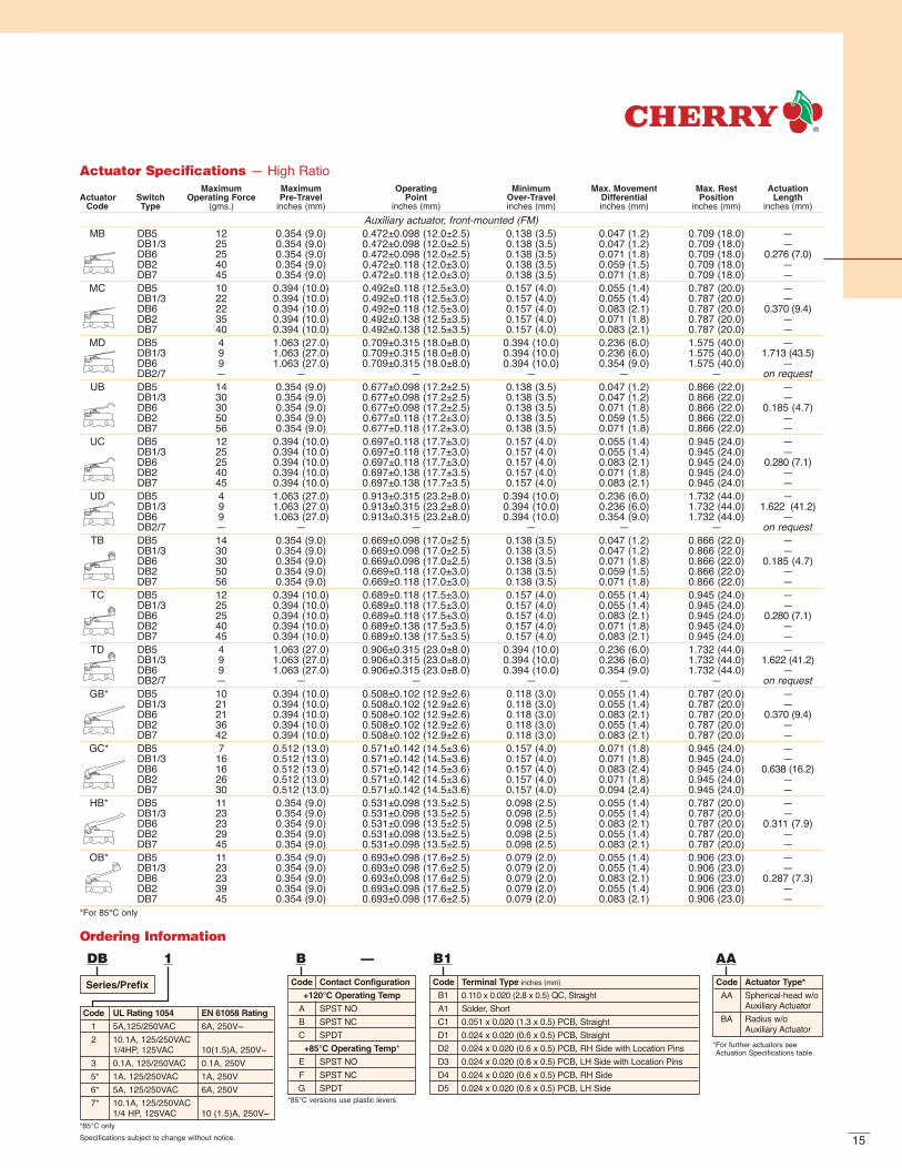
Ordering Information
DB 1 B — B1 AA
Series/Prefix
Code UL Rating 1054 EN 61058 Rating
1 5A,125/250VAC 6A, 250V~2 10.1A, 125/250VAC
1/4HP, 125VAC 10(1.5)A, 250V~3 0.1A, 125/250VAC 0.1A, 250V5* 1A, 125/250VAC 1A, 250V6* 5A, 125/250VAC 6A, 250V7* 10.1A, 125/250VAC
1/4 HP, 125VAC 10 (1.5)A, 250V~
Code Contact Configuration
+120°C Operating Temp
A SPST NOB SPST NCC SPDT
+85°C Operating Temp*E SPST NOF SPST NCG SPDT
Code Terminal Type inches (mm)
B1 0.110 x 0.020 (2.8 x 0.5) QC, Straight A1 Solder, ShortC1 0.051 x 0.020 (1.3 x 0.5) PCB, StraightD1 0.024 x 0.020 (0.6 x 0.5) PCB, Straight D2 0.024 x 0.020 (0.6 x 0.5) PCB, RH Side with Location Pins D3 0.024 x 0.020 (0.6 x 0.5) PCB, LH Side with Location PinsD4 0.024 x 0.020 (0.6 x 0.5) PCB, RH Side D5 0.024 x 0.020 (0.6 x 0.5) PCB, LH Side
Code Actuator Type*
AA Spherical-head w/oAuxiliary Actuator
BA Radius w/o Auxiliary Actuator
*85°C only
*85°C versions use plastic levers
Specifications subject to change without notice.
*For further actuators see Actuation Specifications table.
Actuator Specifications — High RatioMaximum Maximum Operating Minimum Max. Movement Max. Rest Actuation
Actuator Switch Operating Force Pre-Travel Point Over-Travel Differential Position Length Code Type (gms.) inches (mm) inches (mm) inches (mm) inches (mm) inches (mm) inches (mm)
Auxiliary actuator, front-mounted (FM)MB DB5 12 0.354 (9.0) 0.472±0.098 (12.0±2.5) 0.138 (3.5) 0.047 (1.2) 0.709 (18.0) —
DB1/3 25 0.354 (9.0) 0.472±0.098 (12.0±2.5) 0.138 (3.5) 0.047 (1.2) 0.709 (18.0) —DB6 25 0.354 (9.0) 0.472±0.098 (12.0±2.5) 0.138 (3.5) 0.071 (1.8) 0.709 (18.0) 0.276 (7.0)DB2 40 0.354 (9.0) 0.472±0.118 (12.0±3.0) 0.138 (3.5) 0.059 (1.5) 0.709 (18.0) —DB7 45 0.354 (9.0) 0.472±0.118 (12.0±3.0) 0.138 (3.5) 0.071 (1.8) 0.709 (18.0) —
MC DB5 10 0.394 (10.0) 0.492±0.118 (12.5±3.0) 0.157 (4.0) 0.055 (1.4) 0.787 (20.0) —DB1/3 22 0.394 (10.0) 0.492±0.118 (12.5±3.0) 0.157 (4.0) 0.055 (1.4) 0.787 (20.0) —DB6 22 0.394 (10.0) 0.492±0.118 (12.5±3.0) 0.157 (4.0) 0.083 (2.1) 0.787 (20.0) 0.370 (9.4)DB2 35 0.394 (10.0) 0.492±0.138 (12.5±3.5) 0.157 (4.0) 0.071 (1.8) 0.787 (20.0) —DB7 40 0.394 (10.0) 0.492±0.138 (12.5±3.5) 0.157 (4.0) 0.083 (2.1) 0.787 (20.0) —
MD DB5 4 1.063 (27.0) 0.709±0.315 (18.0±8.0) 0.394 (10.0) 0.236 (6.0) 1.575 (40.0) —DB1/3 9 1.063 (27.0) 0.709±0.315 (18.0±8.0) 0.394 (10.0) 0.236 (6.0) 1.575 (40.0) 1.713 (43.5)DB6 9 1.063 (27.0) 0.709±0.315 (18.0±8.0) 0.394 (10.0) 0.354 (9.0) 1.575 (40.0) —DB2/7 — — — — — — on request
UB DB5 14 0.354 (9.0) 0.677±0.098 (17.2±2.5) 0.138 (3.5) 0.047 (1.2) 0.866 (22.0) —DB1/3 30 0.354 (9.0) 0.677±0.098 (17.2±2.5) 0.138 (3.5) 0.047 (1.2) 0.866 (22.0) —DB6 30 0.354 (9.0) 0.677±0.098 (17.2±2.5) 0.138 (3.5) 0.071 (1.8) 0.866 (22.0) 0.185 (4.7)DB2 50 0.354 (9.0) 0.677±0.118 (17.2±3.0) 0.138 (3.5) 0.059 (1.5) 0.866 (22.0) —DB7 56 0.354 (9.0) 0.677±0.118 (17.2±3.0) 0.138 (3.5) 0.071 (1.8) 0.866 (22.0) —
UC DB5 12 0.394 (10.0) 0.697±0.118 (17.7±3.0) 0.157 (4.0) 0.055 (1.4) 0.945 (24.0) —DB1/3 25 0.394 (10.0) 0.697±0.118 (17.7±3.0) 0.157 (4.0) 0.055 (1.4) 0.945 (24.0) —DB6 25 0.394 (10.0) 0.697±0.118 (17.7±3.0) 0.157 (4.0) 0.083 (2.1) 0.945 (24.0) 0.280 (7.1)DB2 40 0.394 (10.0) 0.697±0.138 (17.7±3.5) 0.157 (4.0) 0.071 (1.8) 0.945 (24.0) —DB7 45 0.394 (10.0) 0.697±0.138 (17.7±3.5) 0.157 (4.0) 0.083 (2.1) 0.945 (24.0) —
UD DB5 4 1.063 (27.0) 0.913±0.315 (23.2±8.0) 0.394 (10.0) 0.236 (6.0) 1.732 (44.0) —DB1/3 9 1.063 (27.0) 0.913±0.315 (23.2±8.0) 0.394 (10.0) 0.236 (6.0) 1.732 (44.0) 1.622 (41.2)DB6 9 1.063 (27.0) 0.913±0.315 (23.2±8.0) 0.394 (10.0) 0.354 (9.0) 1.732 (44.0) —DB2/7 — — — — — — on request
TB DB5 14 0.354 (9.0) 0.669±0.098 (17.0±2.5) 0.138 (3.5) 0.047 (1.2) 0.866 (22.0) —DB1/3 30 0.354 (9.0) 0.669±0.098 (17.0±2.5) 0.138 (3.5) 0.047 (1.2) 0.866 (22.0) —DB6 30 0.354 (9.0) 0.669±0.098 (17.0±2.5) 0.138 (3.5) 0.071 (1.8) 0.866 (22.0) 0.185 (4.7)DB2 50 0.354 (9.0) 0.669±0.118 (17.0±3.0) 0.138 (3.5) 0.059 (1.5) 0.866 (22.0) —DB7 56 0.354 (9.0) 0.669±0.118 (17.0±3.0) 0.138 (3.5) 0.071 (1.8) 0.866 (22.0) —
TC DB5 12 0.394 (10.0) 0.689±0.118 (17.5±3.0) 0.157 (4.0) 0.055 (1.4) 0.945 (24.0) —DB1/3 25 0.394 (10.0) 0.689±0.118 (17.5±3.0) 0.157 (4.0) 0.055 (1.4) 0.945 (24.0) —DB6 25 0.394 (10.0) 0.689±0.118 (17.5±3.0) 0.157 (4.0) 0.083 (2.1) 0.945 (24.0) 0.280 (7.1)DB2 40 0.394 (10.0) 0.689±0.138 (17.5±3.5) 0.157 (4.0) 0.071 (1.8) 0.945 (24.0) —DB7 45 0.394 (10.0) 0.689±0.138 (17.5±3.5) 0.157 (4.0) 0.083 (2.1) 0.945 (24.0) —
TD DB5 4 1.063 (27.0) 0.906±0.315 (23.0±8.0) 0.394 (10.0) 0.236 (6.0) 1.732 (44.0) —DB1/3 9 1.063 (27.0) 0.906±0.315 (23.0±8.0) 0.394 (10.0) 0.236 (6.0) 1.732 (44.0) 1.622 (41.2)DB6 9 1.063 (27.0) 0.906±0.315 (23.0±8.0) 0.394 (10.0) 0.354 (9.0) 1.732 (44.0) —DB2/7 — — — — — — on request
GB* DB5 10 0.394 (10.0) 0.508±0.102 (12.9±2.6) 0.118 (3.0) 0.055 (1.4) 0.787 (20.0) —DB1/3 21 0.394 (10.0) 0.508±0.102 (12.9±2.6) 0.118 (3.0) 0.055 (1.4) 0.787 (20.0) —DB6 21 0.394 (10.0) 0.508±0.102 (12.9±2.6) 0.118 (3.0) 0.083 (2.1) 0.787 (20.0) 0.370 (9.4)DB2 36 0.394 (10.0) 0.508±0.102 (12.9±2.6) 0.118 (3.0) 0.055 (1.4) 0.787 (20.0) —DB7 42 0.394 (10.0) 0.508±0.102 (12.9±2.6) 0.118 (3.0) 0.083 (2.1) 0.787 (20.0) —
GC* DB5 7 0.512 (13.0) 0.571±0.142 (14.5±3.6) 0.157 (4.0) 0.071 (1.8) 0.945 (24.0) —DB1/3 16 0.512 (13.0) 0.571±0.142 (14.5±3.6) 0.157 (4.0) 0.071 (1.8) 0.945 (24.0) —DB6 16 0.512 (13.0) 0.571±0.142 (14.5±3.6) 0.157 (4.0) 0.083 (2.4) 0.945 (24.0) 0.638 (16.2)DB2 26 0.512 (13.0) 0.571±0.142 (14.5±3.6) 0.157 (4.0) 0.071 (1.8) 0.945 (24.0) —DB7 30 0.512 (13.0) 0.571±0.142 (14.5±3.6) 0.157 (4.0) 0.094 (2.4) 0.945 (24.0) —
HB* DB5 11 0.354 (9.0) 0.531±0.098 (13.5±2.5) 0.098 (2.5) 0.055 (1.4) 0.787 (20.0) —DB1/3 23 0.354 (9.0) 0.531±0.098 (13.5±2.5) 0.098 (2.5) 0.055 (1.4) 0.787 (20.0) —DB6 23 0.354 (9.0) 0.531±0.098 (13.5±2.5) 0.098 (2.5) 0.083 (2.1) 0.787 (20.0) 0.311 (7.9)DB2 29 0.354 (9.0) 0.531±0.098 (13.5±2.5) 0.098 (2.5) 0.055 (1.4) 0.787 (20.0) —DB7 45 0.354 (9.0) 0.531±0.098 (13.5±2.5) 0.098 (2.5) 0.083 (2.1) 0.787 (20.0) —
OB* DB5 11 0.354 (9.0) 0.693±0.098 (17.6±2.5) 0.079 (2.0) 0.055 (1.4) 0.906 (23.0) —DB1/3 23 0.354 (9.0) 0.693±0.098 (17.6±2.5) 0.079 (2.0) 0.055 (1.4) 0.906 (23.0) —DB6 23 0.354 (9.0) 0.693±0.098 (17.6±2.5) 0.079 (2.0) 0.083 (2.1) 0.906 (23.0) 0.287 (7.3)DB2 39 0.354 (9.0) 0.693±0.098 (17.6±2.5) 0.079 (2.0) 0.055 (1.4) 0.906 (23.0) —DB7 45 0.354 (9.0) 0.693±0.098 (17.6±2.5) 0.079 (2.0) 0.083 (2.1) 0.906 (23.0) —
*For 85°C only

SUBMINIATURE
ESeries
Stainless steel spring
Thermoplasticactuating button
Thermoplasticcase
Silver contacts orgold crosspointcontacts
Common terminal
NC terminal
NO terminal
Copper alloy blade
Features 4 current ratings Choice of actuator 5 terminal types 3 contact arrangements Long life coil spring mechanism DC ratings available upon request High-temperature version available
Subminiature modules take less space than individual subminiature switches fastened side-by-side. For applicationsrequiring 2, 3, 4 or 5-circuit control in acompact space, the special molded casedesign helps speed assembly since there is only one part to handle and install ratherthan 2, 3, 4 or 5 individual switches.
SpecificationsElectrical
Temperature Rating: -40° to +85°C, +130° optional using thermoset materialFlammability Rating: UL94HB
Materials
Case: ThermoplasticActuating Button: Thermoplastic AcetalTerminals: Silver-Plated Commercial BronzeMoving Blade: Beryllium CopperSpring: Stainless SteelAuxiliary Actuator: Cold Rolled Steel (Nickel-Plated)Contacts: Fine Silver (except E63 — Gold Crosspoint)
Electrical RatingsElectrical Life at Rated Load
Switch According to VDE According to ULSeries EN61058 Rating UL1054 Rating (Min. Operations) (Min. Operations)
E61 N/A 5A, 125/250VAC N/A 6,0005A, 30VDC (optional)
E62 N/A 10.1A, 125/250VAC; 1/4HP, 125VAC N/A 6,000E63 N/A 0.1A, 125VAC N/A 6,000*
0.25A, 30VDC (optional)
E64 N/A 13A, 125VAC; 10.1A, 250VAC N/A 6,000*Indicates 100K life available.
17
0.781(19.84)
0.250(6.35)
0.093(2.36)
0.093(2.36)
0.300(7.62)
0.375(9.53)
0.352(8.94)
0.093(2.36)
0.087 (2.21)0.095 (2.41)
0.405(10.29)
0.073(1.85)
0.237(6.02)
ReferenceLine
0.087 (2.21)0.095 (2.41)
Dia. Hole
0.094 (2.39)0.109 (2.77)
0.375(9.53
0.0050.13)
+-+-
COM N.O. N.C.
NominalOperatePosition
0.143 (3.63)0.093 (2.36)
0.110 (2.79) 0.073 (1.85)0.032 (0.81)
0.051 (1.30)
0.177(4.50)
0.160(4.06)
0.191(4.85)
0.344(8.74)
0.250(6.35) 0.125
(3.18)
0.058(1.47)
0.050(1.27)
Short SolderQC
QC Barrel
PCB
–10A–00A
–30A –40A
–50A
I.D. withClinch Opening
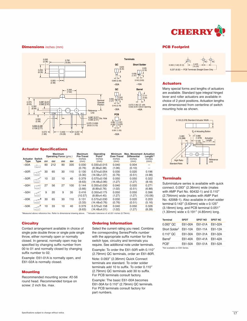
Terminals
Dimensions inches (mm)
0.483(12.268)
ReferenceLine
ActuationLength
0.133 (3.378) Standard Actuator Width
0.125(3.175)
0.066(1.676)
CL of Actuating Button
Standard Ratio
High Ratio
ActuatorsMany special forms and lengths of actuatorsare available. Standard type integral hingedlever and roller actuators are available inchoice of 2 pivot positions. Actuation lengthsare dimensioned from centerline of switchmounting hole as shown.
Ordering InformationSelect the current rating you need. Combinethe corresponding Series/Prefix numberwith the appropriate suffix number for theswitch type, circuitry and terminals yourequire. See additional note under terminals.Example: To order the E61-50R with 0.110″(2.79mm) QC terminals, order an E61-80R.Note: 0.093″ (2.36mm) Quick Connect terminals are standard. To order solder terminals add 10 to suffix. To order 0.110″(2.79mm) QC terminals add 30 to suffix.For PCB terminals consult factory.Example: The basic E61-00A becomesE61-30A for 0.110″ (2.79mm) QC terminals.For PCB terminals consult factory for part numbers.
Specifications subject to change without notice.
PCB Footprint
0.405(10.29)
0.237 (6.02) — PCB Terminals Straight Down Only
NCNOC
0.063 (1.60) Ø (3)
CircuitryContact arrangement available in choice ofsingle pole double throw or single pole singlethrow, either normally open or normallyclosed. In general, normally open may bespecified by changing suffix number from00 to 01 and normally closed by changingsuffix number to 02. Example: E61-01A is normally open, andE61-02A is normally closed.
MountingRecommended mounting screw: #2-56round head. Recommended torque on screw: 2 inch lbs. max.
TerminalsSubminiature series is available with quickconnect. 0.093″ (2.36mm) wide (mates with AMP Part No. 60432-1) and 0.110″(2.794mm) wide (mates with AMP Part No. 42068-1). Also available in short solderterminal 0.143″ (3.63mm) wide x 0.125″(3.18mm) long, and PCB terminal 0.051″(1.30mm) wide x 0.191″ (4.85mm) long.
Terminal SPDT SPST NO SPST NC
0.093″ QC E61-00A E61-01A E61-02AShort Solder† E61-10A E61-11A E61-12A0.110″ QC E61-30A E61-31A E61-32ABarrel† E61-40A E61-41A E61-42APCB† E61-50A E61-51A E61-52A†Not available on E64 Series.
Actuator SpecificationsMaximum Maximum Operating Minimum Max. Movement Actuation
Operating Force (gms.) Pre-Travel Point* Over-Travel Differential Length** Actuator Switch inches inches inches inches inches
Type Type E61 E62 E63 E64 (mm) (mm) (mm) (mm) (mm)–00A 90 212 90 335 0.030 0.330±0.015 0.040 0.004 —
(0.76) (8.38±0.38) (1.06) (0.10) —–00R 30 65 30 110 0.130 0.574±0.054 0.030 0.020 0.196
(3.30) (14.58±1.37) (0.76) (0.51) (4.98)–50R 10 22 10 40 0.379 0.570±0.156 0.050 0.050 0.322
(9.63) (14.48±3.96) (1.27) (1.27) (8.18)–00H 27 56 27 100 0.144 0.350±0.030 0.040 0.020 0.271
(3.66) (8.89±0.76) (1.02) (0.51) (6.88)–50H 9 20 9 35 0.416 0.350±0.175 0.050 0.050 0.396
(10.57) (8.89±4.45) (1.27) (1.27) (10.06)–00K 30 65 30 110 0.131 0.570±0.030 0.030 0.020 0.203
(3.33) (14.48±0.76) (0.76) (0.51) (5.16)–50K 10 33 10 40 0.379 0.570±0.158 0.040 0.050 0.326
(9.63) (14.48±4.01) (1.02) (1.27) (8.28)*Measured above reference line. Refer to dimensional drawing above. **Actuator tolerance of ±0.031 inches (0.79mm).

18
0.093(2.36)
0.250(6.35)
DimensionA
0.781(19.84)
0.200(5.08)
0.237(6.02)
0.405(10.29)
0.103(2.62)
0.020(0.51)
(3 places)
0.094 (2.39)0.109 (2.77)
0.483(12.27)
0.093(2.36)
0.087 (2.21)0.095 (2.41) Reference
Line
0.087 (2.21) Dia0.095 (2.41) Hole
0.375(9.53
0.0050.13)
+-+-
COM N.O. N.C.
0.143 (3.63)0.093 (2.36) 0.110 (2.80) 0.051 (1.30)
–10A*–00A –30A –50A*
0.160(4.06)
0.191(4.85)
0.344(8.74)
0.250(6.35) 0.125
(3.18)
0.058(1.47)
0.050(1.27)
ShortSolder
QC QC PCB
2 PDT 0.470±0.020 (11.934±0.51)3 PDT 0.672±0.020 (17.07±0.51)4 PDT 0.875±0.020 (22.23±0.51)5 PDT 1.086±0.020 (27.58±0.51)
A Dimension
Terminals
*Not available on E64 Series
Part Number Suffix
Switch Type Terminal 2PDT 3PDT 4PDT 5PDT
0.093″ (2.362mm) QC –02HM –03HM –04HM –05HMSolder –12HM –13HM –14HM –15HM
0.110″ (2.794mm) QC –32HM –33HM –34HM –35HMStandard Ratio PCB Consult Factory
0.093″ (2.362mm) QC –52HM –53HM –54HM –55HMSolder –62HM –63HM –64HM –65HM
0.110″ (2.794mm) QC –82HM –83HM –84HM –85HMHigh Ratio PCB Consult Factory
Dimensions — Modules inches (mm)
Specifications subject to change without notice.
Ordering Information — ModulesSelect the current rating you need. Combine the corresponding Series/Prefix number withthe appropriate suffix number for the switch type and terminals you require. Moduleconstruction not available for E64.*For additional actuator styles consult factory.
0.483(12.268)
ReferenceLine
ActuationLength
0.133 (3.378) Standard Actuator Width
0.125(3.175)
0.066(1.676)
CL of Actuating Button
Standard Ratio
High Ratio
Actuators — ModulesMany special forms and lengths of actuatorsare available. Standard type integral hingedlever and roller actuators are available inchoice of 2 pivot positions. Actuation lengthsare dimensioned from centerline of switchmounting hole as shown.
PCB Footprint — Modules
0.405(10.29)
0.237 (6.02) — PCB Terminals Straight Down Only
NCNOC
0.063 (1.60) Ø (3)
Terminals — ModulesSubminiature modules are available with quick connect. 0.093″ (2.362mm) wide (mates withAMP Part No. 60432-1) and 0.110″ (2.794mm) wide (mates with AMP Part No. 42068-1).Also available in short solder terminal 0.143″ (3.632mm) wide x 0.125″ (3.175mm) long, andPCB terminal 0.051″ (1.295mm) wide x 0.191″ (4.851mm) long.

19
SUBMINIATURE — SEALED
DC Series
SpecificationsElectrical
Temperature Rating: -40° to +85°C /+120°C (without wire leads)-40° to +85C / +105°C (with wire leads)
Flammability Rating: UL94V-O (PET, PBT)UL94HB (POM)
Materials
Case: PET / PBTActuator: POM (T85), PBT (T120)
Auxiliary Actuator: Stainless Steel or PlasticTerminals: Silver-Plated Copper-ZincContacts: Silver Alloy (DC3 — Gold Crosspoint)PBT = Polybutyleneterephthalate • PET = Polyethyleneterephthalate • POM = Polyacetal
Stainless steel spring
Thermoplasticactuating button
Thermoplasticcase and cover Silicon gasket
Common terminal
NC terminal
NO terminal
Silver-nickel orgold crosspoint contacts
Electrical RatingsElectrical Life at Rated Load
Switch According to EN According to ULSeries EN61058 Rating UL1054 Rating (Min. Operations) (Min. Operations)
DC1 6A, 250V~ 5A, 125/250VAC; 1A, 48VDC 10,000 6,000DC2 10(1.5)A, 250V~ 10.1A, 125/250VAC; 1/4HP, 125VAC 10,000 6,000DC3 0.1A, 250V~ 0.1A, 125/250VAC 50,000 6,000DC4 3A, 250V~ 3A, 125/250VAC 50,000 6,000
Features
Enclosed switch complying with IP 6K7
Silicon-free version available
Models available for operating temperatures up to 120°C
Rated for currents up to 10 amp at 250VAC
Range of auxiliary actuators available(can also be retrofitted)
Various contact materials available,depending on application
Mechanical life: min. 1 x10⁶ operations
Wide variety of connection options

20
Straight (120°C Rated)
Plastic Straight (85°C Rated)
Roller
Plastic RollerPlastic Simulated Roller
Operating PointRest Position»L« ±0.03
(±0.8)
»L« ±0.03(±0.8)
R 0.10(2.5)
R 2 ø5
ø0.19(ø4.8)
0.14
(3.5
)
0.14
(3.5
)
»L« ±0.03(±0.8)
»L« ±0.03(±0.8)
0.14
(3.5
)0.
14(3
.5)
»L« ±0.03(±0.8)
»L« ±0.03(±0.8)
0.11
(2.9
)≥0
.22
(≥5.
6)≥0
.22
(≥5.
5)
0.14
(3.3
)
Auxiliary Actuators inches (mm)
Specifications subject to change without notice.
Actuator Specifications Maximum Maximum Operating Max. Movement
Operating Force Pre-Travel Point Differential(cN) inches (mm) inches (mm) Minimum inches (mm) Max. Rest Actuation
Over-Travel Position LengthActuator Switch DC1, DC1, DC1, inches DC1, inches inches
Code Type DC3, DC4 DC2 DC3, DC4 DC2 DC3, DC4 DC2 (mm) DC3, DC4 DC2 (mm) (mm)AA 200 340 0.04 0.04 0.33±0.01 0.33±0.01 0.02 0.004 0.004 0.37 —
(1.0) (1.0) (8.4±0.3) (8.4±0.3) (0.6) (0.10) (0.10) (9.3) —LB 80 150 0.18 0.20 0.42±0.05 0.42±0.06 0.06 0.02 0.03 0.55 0.189
(4.5) (5.0) (10.7±1.3) (10.7±1.6) (1.5) (0.5) (0.7) (14.0) (4.8)LC 70 120 0.20 0.22 0.44±0.06 0.44±0.07 0.06 0.02 0.04 0.59 0.276
(5.0) (5.5) (11.1±1.5) (11.1±1.8) (1.5) (0.6) (1.0) (15.0) (7.0)LD forces and travel available upon request 1.654
(42.0)SB 90 160 0.18 0.20 0.63±0.05 0.63±0.06 0.06 0.02 0.03 0.75 0.098
(4.5) (5.0) (16.0±1.3) (16.0±1.6) (1.5) (0.5) (0.7) (19.0) (2.5)SC 80 130 0.20 0.22 0.65±0.06 0.65±0.07 0.06 0.02 0.04 0.79 0.185
(5.0) (5.5) (16.4±1.5) (16.4±1.8) (1.5) (0.6) (1.0) (20.0) (4.7)SD forces and travel available upon request 1.563
(39.7)RB 90 160 0.18 0.20 0.62±0.05 0.62±0.06 0.06 0.02 0.03 0.75 0.098
(4.5) (5.0) (15.8±1.3) (15.8±1.6) (1.5) (0.5) (0.7) (19.0) (2.5)RC 80 130 0.20 0.22 0.64±0.06 0.64±0.07 0.06 0.02 0.04 0.79 0.185
(5.0) (5.5) (16.2±1.5) (16.2±1.8) (1.5) (0.6) (1.0) (20.0) (4.7)RD forces and travel available upon request 1.563
(39.7)WB 68 115 0.18 0.18 0.44±0.06 0.44±0.06 0.08 0.02 0.02 0.59 0.276
(4.5) (4.5) (11.1±1.5) (11.1±1.5) (2.0) (0.6) (0.6) (15.0) (7.0)WC 50 85 0.24 0.24 0.48±0.07 0.48±0.07 0.12 0.03 0.03 0.67 0.551
(6.0) (6.0) (12.2±1.8) (12.2±1.8) (3.0) (0.8) (0.8) (17.0) (14.0)VB 73 125 0.18 0.18 0.47±0.06 0.47±0.06 0.08 0.02 0.02 0.59 0.220
(4.5) (4.5) (11.9±1.4) (11.9±1.4) (2.0) (0.6) (0.6) (15.0) (5.6)ZB 73 125 .018 0.18 0.63±0.06 0.63±0.06 0.06 0.02 0.02 0.75 0.205
(4.5) (4.5) (16.0±1.4) (16.0±1.4) (1.5) (0.6) (0.6) (19.0) (5.2)
21Specifications subject to change without notice.
NO Lead (Blue)
NC Lead (Grey)
min. 19.69 (500) max. 0.78 (20) min. 19.69 (500)
Rest Position
Operating Point
0.30(7.5)
0.19(4.85)
ø0.09(ø2.2)
0.10(2.54)
0.38(9.53)
0.20(5.16)
0.27
(6.9
)
(
Type A
Type B
Cut-out
Special Model Availablewith Tail Pedestal on Request
0.3
(7.7
)m
ax.
0.34
(8.6
)m
ax.
0.30
(7.7
)m
ax.
0.26
(6.6
5)
Model with Connecting Leads
0.09
(2.2
5)
0.26(6.5)
ø0.09(ø2.2)
0.38(9.53)
0.20(5.16)
0.30(7.5)
0.30(7.5)
0.11(2.73)
0.10(2.54)
0.09
(2.2
5)
0.09
(2.3
5)
0.30(7.5)
max. 0.79 (20)
0.19(4.85)
Rest PositionOperating Point
0.27
(6.9
)
0.24
(6.0
5)
0.26
(6.6
5)
COM Lead(Black)
0.24
(6.0
5)
DC 3 G B 3 L C
Series/Prefix
Code UL Rating EN 61058 Rating
1 5A,125/250VAC 6A, 250V~1A 48VDC
2 10.1A, 125/250VAC1/4HP, 125VAC 10(1.5)A, 250V~
3 0.1A, 125/250VAC 0.1A, 250V~0.1A 30VDC**
44 3A, 250VAC 3A, 250V~1A 48VDC
Contact Configuration
+105°/120°C Operating Temp +85°C Operating Temp*Code Code
A SPST NO E SPST NOB SPST NC F SPST NCC SPDT G SPDT
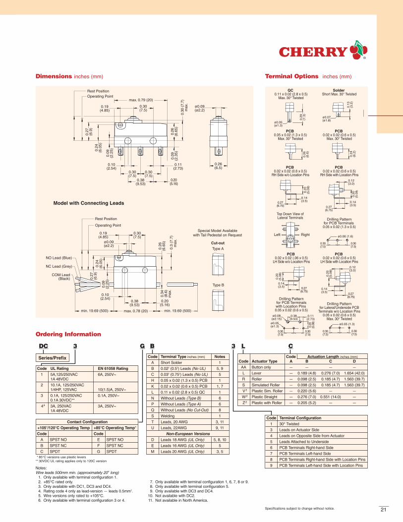
Code Terminal Type inches (mm) Notes
A Short Solder 1B 0.022 (0.52) Leads (No UL) 5, 9C 0.032 (0.752) Leads (No UL) 5H 0.05 x 0.02 (1.3 x 0.5) PCB 1K 0.02 x 0.02 (0.6 x 0.5) PCB 1, 7L 0.11 x 0.02 (2.8 x 0.5) QC 1N Without Leads (Type B) 6P Without Leads (Type A) 6Q Without Leads (No Cut-Out) 8S Welding 1T Leads, 20 AWG 3, 11U Leads, 22AWG 9, 11
Non-European VersionsD Leads 18 AWG (UL Only) 5, 8, 10E Leads 16 AWG (UL Only) 5M Leads 20 AWG (UL Only) 3, 5
Code Terminal Configuration
1 30° Twisted3 Leads on Actuator Side4 Leads on Opposite Side from Actuator5 Leads Attached to Underside6 PCB Terminals Right-hand Side7 PCB Terminals Left-hand Side8 PCB Terminals Right-hand Side with Location Pins9 PCB Terminals Left-hand Side with Location Pins
Code Actuation Length inches (mm)Code Actuator Type A B C D
AA Button only — — — —L Lever — 0.189 (4.8) 0.276 (7.0) 1.654 (42.0)R Roller — 0.098 (2.5) 0.185 (4.7) 1.563 (39.7)S Simulated Roller — 0.098 (2.5) 0.185 (4.7) 1.563 (39.7)V2 Plastic Sim. Roller — 0.220 (5.6) — —W2 Plastic Straight — 0.276 (7.0) 0.551 (14.0) —Z2 Plastic with Roller — 0.205 (5.2) — —
Ordering Information
Dimensions inches (mm)
ø0.07(ø1.8)
ø0.05(ø1.3)
0.29
(7.3
)
0.13
(3.2
)
0.26
(6.6
)
0.24
(6.2
)
0.27(6.75)
0.14(3.5)
0.20
(5.0
8)
0.12(3.0)
0.20
(5.0
8)
0.12(3.0)
0.20
(5.0
8)
0.14(3.5)
0.14(3.5)
0.27(6.75)
0.27(6.75)
0.27(6.75)
0.14(3.5)
0.20
(5.0
8)
QC 0.11 x 0.02 (2.8 x 0.5)
Max. 30° Twisted
Solder Short Max. 30° Twisted
PCB 0.05 x 0.02 (1.3 x 0.5)
Max. 30° Twisted
PCB 0.02 x 0.02 (0.6 x 0.5)
Max. 30° Twisted
PCB 0.02 x 0.02 (0.6 x 0.5)
RH Side w/o Location Pins
PCB 0.02 x 0.02 (0.6 x 0.5)
RH Side with Location Pins
PCB 0.02 x 0.02 (.06 x 0.5)
LH Side w/o Location Pins
PCB 0.02 x 0.02 (0.6 x 0.5)
LH Side with Location Pins
Top Down View ofLateral Terminals Drilling Pattern
for PCB Terminals 0.05 x 0.02 (1.3 x 0.5)
Drilling Patternfor PCB Terminalswith Location Pins 0.05 x 0.02 (0.6 x 0.5)
Drilling Patternfor Lateral/Underside PCB
Terminals w/o Location Pins0.05 x 0.02 (0.6 x 0.5)
Max. 30° Twisted
ø0.06 (1.6)
0.30(7.5)
0.30(7.5)
ø0.05 (1.3)ø0.05(ø1.3)
ø0.08(ø2.15)
0.38(9.53)
0.11(2.73)
0.30(7.5)
0.30(7.5)
0.20
(5.0
8)
Left Right
0.30(7.5)
0.30(7.5)
Terminal Options inches (mm)
Notes:Wire leads 500mm min. (approximately 20″ long)
1. Only available with terminal configuration 1.2. +85°C rated only.3. Only available with DC1, DC3 and DC4.4. Rating code 4 only as lead-version — leads 0.5mm2.5. Wire versions only rated to +105°C.6. Only available with terminal configuration 3 or 4.
7. Only available with terminal configuration 1, 6, 7, 8 or 9.8. Only available with terminal configuration 5.9. Only available with DC3 and DC4.
10. Not available with DC2.11. Not available in North America.
* 85°C versions use plastic levers** 30VDC UL rating applies only to 120C version

SUBMINIATURE — SEALED
DKSeries
Stainless steel spring
POMactuating button
Gold-platedberyllium coppermoving blade
PBT + ASAcover
Stainless steelinternal actuator
PBT base
Goldcrosspointcontacts
Silver-plated copper-zincterminalsCommon terminal
NO terminalNC terminal
Features
Enclosed switch complying with IP 6K5. IP 6K7 available on request
Very small dimensions, 0.579″ x 0.213″ x 0.268″(14.7mm x 5.4mm x 6.8mm)
Models available for operatingtemperatures up to 105°C
Rated for 5mA@12VDC or 2A@12VDC
Can be actuated vertically or by auxiliary actuator
Gold crosspoint contacts for high contact stability
Mechanical life: min. 500,000 operations
Wide variety of connection options, also available with leads
SpecificationsElectrical
Temperature Rating: -40°C to +85°CFlammability Rating: N/A
Materials
Base: PBTCover: PBT + ASAActuator: POM (+85°C)
Auxiliary Actuator: Stainless SteelInternal Actuator: Stainless SteelSpring: Stainless SteelMoving Blade: Gold-Plated Beryllium CopperTerminals: Silver-Plated Copper-ZincContacts: Gold CrosspointGasket: SiliconASA = Acrylonitrile-styrene-acrylicester • PBT = Polybutyleneterephthalate • POM = Polyacetal

23
Rest Position max 0.146 (3.7)
Operating Point 0.120 ±0.008 (3.05 ±0.20)
End Position 0.063 ±0.024 (1.6 ±0.6)
Rest Position max 0.146 (3.7)Operating Point 0.120 ±0.008 (3.05 ±0.20)
End Position 0.063 ±0.024 (1.6 ±0.6)
0.579(14.7)
0.480(12.2)
0.02
4(0
.6)
0.14
6(3
.7)
0.26
8(6
.8)
0.21
3(5
.4)
0.102(2.6)
0.19
7(5
.0)
ø0.087(ø2.2) 0.375
(9.53)0.478
(12.13)0.
024
(0.6
)
0.14
6(3
.7)
max
0.
476
(12.
0)
NC Lead (Grey)
NO Lead (Blue)
COM Lead (Black)
»L«
DK Sub-subminiature Switch with Leads
(IP6K7 Complaint)
Dimensions inches (mm)
Solder Terminals0.098 x 0.020 (2.5 x 0.5)
Top-down View of Lateral Terminals Drilling Patterns for PCB Terminals(Side and Underside)
0.024 x 0.020 (0.6 x 0.5)
PCB Terminals — Straight0.024 x 0.020 (0.6 x 0.5)
PCB TerminalsRH Side with Location Pins
0.024 x 0.020 (0.6 x 0.5)
PCB TerminalsLH Side with Location Pins
0.024 x 0.020 (0.6 x 0.5)
Left Right
0.200(5.08)
0.200(5.08)
Ø0.051 +0.004(Ø1.30 +0.10)
0.127(3.22)
0.098(2.5)
0.163(4.13) 0.163
(4.13)
0.06
7(1
.7)
0.197(5.0)
0.23
0(5
.85)
0.112(2.85)
0.09
8(2
.5)
0.089(2.27)
0.200(5.08) 0.200
(5.08)
0.024(0.6)
0.197(5.0)
0.23
0(5
.85)
0.112(2.85)
Terminal Options inches (mm)
Straight
Simulated Roller
0.13
4(3
.40)
0.13
4(3
.40)
Rest PositionOperating Point
Operating PointRest Position
L1
L1
Auxiliary Actuators inches (mm)
Specifications subject to change without notice.
Series/Prefix
Ordering Information
DK 1 G TR A0
Code Current Rating
1 0.005A@12VDCor 2A@12VDC
Code Terminal Type inches (mm)
RN 0.098 x 0.020 (2.5 x 0.5) Solder, Straight w/o PinsRR 0.098 x 0.020 (2.5 x 0.5) Solder, Straight with RH PinsRL 0.098 x 0.020 (2.5 x 0.5) Solder, Straight with LH PinsSN 0.024 x 0.020 (0.6 x 0.5) PCB, Straight w/o PinsSR 0.024 x 0.020 (0.6 x 0.5) PCB, Straight with RH PinsSL 0.024 x 0.020 (0.6 x 0.5) PCB, Straight with LH PinsTR 0.024 x 0.020 (0.6 x 0.5) PCB, RH Side with RH PinsUL 0.024 x 0.020 (0.6 x 0.5) PCB, LH Side with LH PinsW3 9.843 (250) Leads 0.0142 (0.352) to Underside w/o PinsW9 9.843 (250) Leads 0.0142 (0.352) to Underside with RH PinsW6 9.843 (250) Leads 0.0142 (0.352) to Underside with LH PinsZ3 19.685 (500) Leads 0.0142 (0.352) to Underside w/o PinsZ9 19.685 (500) Leads 0.0142 (0.352) to Underside with RH PinsZ6 19.685 (500) Leads 0.0142 (0.352) to Underside with LH Pins
Code Actuator Type
A0 Without Auxiliary ActuatorD1 Straight Spring-Loaded Auxiliary ActuatorE1 Simulated Roller, Spring-Loaded
Code Contact Configuration
G SPDTVersion with Leads
E SPST NOF SPST NC

SUBMINIATURE — SEALED
DCJKSeries
Stainless steel spring
Thermoplasticactuating button
Thermoplasticcase and cover Silicon gasket
Common terminal
NC terminal
NO terminal
Silver-nickel orgold crosspoint contacts
SpecificationsElectrical
Temperature Rating: -40° to +85°C /+120°C (without wire leads)-40° to +85C / +105°C (with wire leads)
Flammability Rating: UL94V-O (PET)UL94V-2 (PA)UL94HB (POM)
Materials
Base: PETCover: PET/PAActuator: POM (85°C) / PA (120°C)
Auxiliary Actuator: Stainless Steel or PlasticTerminals: Silver-Plated Copper-ZincContacts: Silver Alloy; Silver;
Gold-Plated Silver Crosspoint;Gold Crosspoint
PA = Polyamide • PET = Polyethyleneterephthalate • POM = Polyacetal
Features
Enclosed switch complying with IP 6K7
Silicon-free version available
Models available for operatingtemperatures up to 120°C
Rated for currents up to 10 amp at 250VAC
Range of auxiliary actuators available (can also be retrofitted); two mounting positions
Wide variety of terminal types; 3 pedestal heights
High contact stability thanks to selectionof application-specific contact materials
Mechanical life: min. 2 x 10⁶ operations

25
Rest PositionOperating Point
max
.0.
362
(9.2
)
0.27
2(6
.9)
0.08
9(2
.25)
max. 0.787(20.0)
0.295(7.5)
0.100(2.54)
0.295(7.5)
0.107(2.73)
0.375(9.53)
ø0.087(ø2.2)
0.295(7.5)
0.33
1±0.
012
(8.4
±0.3
)
max
. 0.3
03(7
.7)
max
. 0.0
98(2
.5)
0.203(5.16)
0.251(6.4)
Dimensions inches (mm) Auxiliary ActuatorsSwitches in the DCJK family have twomountings for attaching auxiliary actuators.This, combined with the range of actuatorsavailable in the DC switch family andvarious operating points, means that a wide variety of operating forces and travel combinations is feasible.To find the perfect fit for your requirements, please contact us.
Specifications subject to change without notice.
For customizing to individual requirements, switches in the DCJK family are available with four different switching points.
max
. 0.3
26(9
.2)
max
. 0.3
03(7
.7)
Rest PositionOperating Point
0.33
1±0.
012
(8.4
±0.3
)
max
. 0.3
74(9
.5)
max
. 0.3
03(7
.7)
Rest PositionOperating Point
0.34
3±0.
012
(8.7
±0.3
)
max
. 0.3
82(9
.7)
max
. 0.3
03(7
.7)
Rest PositionOperating Point
0.35
0±0.
012
(8.9
±0.3
)
max
. 0.4
06(1
0.3)
max
. 0.3
23(8
.2)
Rest PositionOperating Point
0.37
0±0.
012
(9.4
±0.3
)
Switching Point Options inches (mm)
ExampleBecause of the huge variety of options available, there is no fully descriptive order code.Please give us details of your requirements so that we can find the right solution to suit your needs and tell you the precise order code to use.
Model with Electrical Leads 0.319 (8.1) from base to drill hole
Model with Electrical Leads 0.205 (5.2) from base to drill hole
min. »L« min. »L« max. 0.787(20.0)
max. 0.375(9.53)
0.203(5.16)
0.100(2.54)
8.08
9(2
.25)
max
.0.3
19(8
.1)
max
. 0.2
05(5
.2)
Leads attached on side opposite actuator
NO Lead (Blue)
NC Lead (Grey)
COM Lead (Black)
Leads attached on actuator side
Dimensions inches (mm)
Series/Prefix Code Pedestal Height
1 Short Pedestal 0.098 (2.5)2 Medium Pedestal 0.205 (5.2)3 Tall Pedestal 0.319 (8.1)
Ordering Information
DCJK 1 2 xx
Serial NumberCode Contact Material
1 Silver Alloy2 Silver3 Gold Crosspoint5 Gold-Plated Silver Crosspoint

SUBMINIATURE — SEALED
DJSeries
Stainless steelinternal actuator
PBT base
Gold crosspoint contacts
Gold-platedberyllium coppermoving blade
POM actuating button
PBT + ASA cover
Stainless steel spring
Silver-plated terminals
Features
Enclosed switch complying with IP 6K7
Suitable for actuation at angles of up to 40°, depending on material used insliding actuator, etc.
Multiple location pins and locating slotsmake installation easy
Very small dimensions
Models available for operatingtemperatures up to 85°C
Rated for 5mA@12VDC or 2A@12VDC
High contact stability due to gold crosspoint contacts
Mechanical life: min. 500,000 operations
Wide variety of connection options
SpecificationsElectrical
Temperature Rating: -40° to +85°CFlammability Rating: N/A
Materials
Base: PBTCover: PBT + ASAActuator: POMInternal Actuator: Stainless SteelSpring: Stainless SteelGasket: SiliconMoving Blade: Gold-Plated Beryllium CopperTerminals: Silver-Plated Copper-ZincContacts: Gold CrosspointASA = Acrylonitrile-styrene-acrylicester • PBT = Polybutyleneterephthalate • POM = Polyacetal

27
Rest Position max. 0.161 (4.1)
Operating Point 0.136±0.008 (3.45±0.20)
0.028(0.7)
0.028(0.7)
0.13
8(3
.5)
0.02
8(0
.7)
0.598(15.2)
0.480(12.2)
0.25
2(6
.4)
0.102(2.6)
0.375(9.53)
0.478(12.13)
ø0.087(ø2.2)
0.19
7(5
.0)
0.15
7(4
.0)
0.02
8(0
.7)
0.13
4(3
.4)
0.32
1(8
.15)
0.06
1(1
.55)
Solder Terminals0.098 x 0.020 (2.5 x 0.5)
PCB Terminals0.028 x 0.020 (0.7 x 0.5)
Drilling Pattern forPCB Terminals
0.028 x 0.020 (0.7 x 0.5)
Top-down View ofLateral Location Pins
0.200(5.08)
0.200(5.08)
Ø0.051 +0.004(Ø1.30 +0.10)
Left Right
0.13
9(3
.53)
0.127(3.22)
0.163(4.13)
0.163(4.13)
0.098(2.5)
0.089(2.27)
0.200(5.08)
0.028(0.7)
0.11
5(2
.93)
0.200(5.08)
DJ 1 G BR AO
Series/Prefix
Code Current Rating
1 0.005A@12VDCor 2A@12VDC
Code Terminal Type inches (mm)
AN 0.098 x 0.020 (2.5 x 0.5) Solder, Straight w/o PinsAL 0.098 x 0.020 (2.5 x 0.5) Solder, Straight with LH PinsAR 0.098 x 0.020 (2.5 x 0.5) Solder, Straight with RH PinsBN 0.028 x 0.020 (0.7 x 0.5) PCB, Straight w/o PinsBL 0.028 x 0.020 (0.7 x 0.5) PCB, Straight with LH PinsBR 0.028 x 0.020 (0.7 x 0.5) PCB, Straight with RH Pins
Code Contact Configuration
G SPDTCode Actuator Type
AO Without Auxiliary Actuator
Ordering Information
Dimensions inches (mm)
Terminal Options inches (mm)
Specifications subject to change without notice.

SUBMINIATURE — SPLASHPROOF
E72/E73 SeriesHi-tempthermoplasticbutton
Hi-tempthermoplasticcover and base
Water-resistantweatherproofhydrin boot
Hi-temppolyethylenewire
Common terminal
NO terminalNC terminal
Features
Moisture resistant
3 contact arrangements
Long life coil spring mechanism
Choice of button or hinged actuator
10″, 16 gauge leads attached
Custom wire and harness designs available upon request
SpecificationsElectrical
Temperature Rating: -40° to +85°CFlammability Rating: UL94V-O
Materials
Case: Hi-Temp Thermoplastic NylonBoot: HydrinButton: Hi-Temp Thermoplastic NylonActuator: Stainless SteelPotting: Macromelt PolyamideContacts: Silver Alloy (E72), Gold Crosspoint (E73)
Electrical RatingsElectrical Life at Rated Load
Switch According to VDE According to ULSeries EN61058 Rating UL1054 Rating (Min. Operations) (Min. Operations)
E72 N/A 10.1A, 1/4HP, 125/250VAC N/A 6,000E73 N/A 0.1A, 125VAC N/A 6,000

29
0.13)
0.230(5.84)0.110
(2.79)
0.180(4.57) Ref
0.748(19.00)
0.110(2.79)
0.142/0.146(3.61/3.71)
Dia
Screw Case
0.915(23.24)
0.385 (9.78)
0.625(15.88
0.0050.13)
+-+-
Hinge Screw Case
0.212(5.38)
0.032 (0.813) 15
0.858(21.79
0.0310.79)
+-+-
0.142/0.144 (3.61/3.66)
0.175 (4.45
0.780(19.81)
0.212(5.38)
0.032 (0.813)
Dimension to C/L of roller0.6500.031 (16.510.79)
150.918
(23.32)Ref.
ReferenceLine
Slotted Dimensions
0.005+-+-
Dimensions inches (mm)
Specifications subject to change without notice.
Characteristics inches (mm)
- 40AT - 40HT - 40KT
Max. Rest Position 0.390 (9.91) 0.972 (24.69) 1.041 (26.44)Max. Pre-travel 0.040 (1.02) 0.275 (6.99) 0.240 (6.10)Operating Point 0.310 – 0.350 0.440 – 0.750 0.762 ±0.125
(7.87 – 8.99) (11.18 – 19.05) (19.36±3.18)Min. Over-travel 0.035 (0.89) 0.100 (2.54) 0.125 (3.18)Max. Movement Differential 0.004 (0.10) 0.024 (0.61) 0.025 (0.635)Max. Operating Force 300 gms. 67 gms. 75 gms.
MountingRecommended screw size: #6-32 roundhead. Recommended torque on screw: 6 inch lbs. max.
Ordering InformationSilver Gold
Actuator Contacts Contacts
Button E72-40AT E73-40ATLever E72-40HT E73-40HTRoller E72-40KT E73-40KT

MINIATURE
D4Series
Reinforced mounting holestotally contained in case toprovide maximum distanceto mounting hardware.Choice of U.S. (#4 screw)or metric (3mm screw)
Flame-retardant, UL94V-Oself-extinguishing case and cover
Long-life stainless steel spring mechanism
ARC-resistant casehas internal barriers4mm minimum betweenlive parts and external hardware
NC terminal
Single or double throw,either normally open or normally closed
NO terminal
Offset terminalsmaintain adequate spacing when quick connects are used.
Common terminal
Features 8 current ratings Choice of actuators Various terminal types 3 contact arrangements Choice of standard or light operating force Long-life coil spring mechanism Agency approved extended life versions ENEC/VDE approval standard on
European versions Stackable case and cover
available upon request
SpecificationsElectrical
Temperature Rating: -40° to +85°C, 125°C or 150°CFlammability Rating: UL94V-OMaterials
Case: Thermoplastic Polyester (PBT), European Versions (PET)Actuating Button: Thermoplastic Acetal (POM), 85°C
Thermoplastic Polyester (PET), 125°C or 150°CAuxiliary Actuator: Aluminum, Stainless Steel or Cold-Rolled Steel (Nickel-Plated)Common Terminal: Silver-Plated BrassNO/NC Terminals: Brass (D40, D41, D42, D43, D44, D49)
Brass (D45, European versions)Copper (D45, US Versions)Silver-Plated Copper (D48, US versions)Copper (D48, European versions)
Moving Blade: Brass (D40, D41, D42, D43)Beryllium Copper (D44, D45, D48)
Contacts: Gold Crosspoint (D40, D41)Silver Alloy (D42, D43, D44, D45, D48, D49)
Electrical RatingsElectrical Life at Rated Load
Switch According to EN According to ULSeries EN61058 Rating UL1054 Rating (Min. Operations) (Min. Operations)
D40 N/A 1.0A, 125VAC NA 6,000*D41 0.1(0.05)A, 250V~ 0.1A, 125/250VAC 50,000 6,000*D42 3(1)A, 250V~ 3A, 125/250VAC; 1/10HP, 250VAC 50,000 6,000*D43 6(2)A, 250V~ 5A, 1/4HP, 125/250VAC 50,000 6,000*D44 10(3)A, 250V~ 10A, 1/2HP, 125/250VAC 50,000 6,000*D45 16(4)A, 250V~ 15A, 1/2HP, 125/250VAC 50,000 6,000*
10(3)A, 400V~ (Std. force only)
D48 21(8)A, 250V~ 21A, 1HP, 125VAC; 2HP, 250VAC 10,000 6,000*D49 N/A 10A, 1/2HP, 125/250VAC; 6A, 30VDC NA 6,000**Operating life for 125°C and 150°C available upon request. *Indicates 100K life available. Consult factory.
European Approved VersionsStandard D4 series switches with metricmounting holes automatically carry ENECapproval. D4 series switches with U.S.mounting holes have optional VDE approval.Contact factory for part number. Switcheswith straight terminals may require insulatedconnectors for international approval.

31
0.109
0.250
0.174
0.070 Dia Hole
0.050 – 0.187 x 0.020 Terminals0.055 – 0.187 x 0.032 Terminals
0.125
0.1870.250
0.4060.625
0.797 0.010+- 0.397
0.549
0.875 0.005+-
0.195
0.181Standard
0.106Optional
1.095 0.015+-
0.406 0.015+-
N.C.
N.O.COM
0.1260.002
Dia. Hole
ReferenceLine
0.114 0.002+- +-
0.114 0.002+-
14.7
±0.5
10.3
3.12.8
13.1
16.2
max
.
20.2522.227.8
2.8
10.310.38+-
3.3
3.1
European Version (mm) U.S. Version (inches)
4.1
RPOP
Dimensions
V1 V3 PA Q1 Q3
PB R1 R3 P5 Y5
*PlugHousing
P4 Z5 B8 S1
C1 C3 W9
0.77 (19.5)0.30 (7.65) 0.2 (5.0)
0.06 (1.6)
0.22 (5.65)
0.22 (5.6)
0.23 (5.75)
0.07 (1.8)
0.17 (4.3)0.79 (20.0)0.07 (1.8)
0.31 (7.8)
0.17
(4.4
)0.
22 (5
.6)
PA P4
0.22
(5.6
)0.
17 (4
.4)
0.79 (20.0)0.07 (1.8)
0.31 (7.8)
0.17 (4.3)
PB P5
Terminals
Drilling Patterns for PCB Terminals
Specifications subject to change without notice.
*Connector Part #623-0518 (mates with Y5 only).
SwitchMountingHole
Actuation Length
0.177 (4.50) 0.355 (9.0)
StandardRatio
HighRatio
Roller
ActuatorsMany special forms and lengths of actuatorsare available. Standard type integral hingedlever and roller actuators are available inchoice of 2 mounting positions. Actuationlengths are dimensioned from centerline of switch mounting hole as shown.
EN (VDE) IdentifiersSwitches with a “standard” operating forceare identified by a ʻYʼ next to the standardmodel description, e.g. D43Y.Switches with a “light” operating force areidentified by an ʻXʼ next to the standardmodel description, e.g. D43X.
Mounting — US VersionRecommended mounting screw size: #4-40 Round head. Recommended torqueon screw: 3 inch lbs. max.
Mounting — European VersionRecommended mounting screw size: M3.Recommended torque on screw: 70N cm max.

32
D4 3 3 V3 L D
Series/Prefix
Code EN61058 UL1054
0 N/A 1.0A, 125VAC1 0.1(0.5)A, 250V 0.1A, 125/250VAC2 3(1)A, 250V 3A, 125/250VAC
1/10HP, 250VAC3 6(2)A, 250V 5A, 1/4HP, 125/250VAC4 10(3)A, 250V 10A, 1/2HP, 125/250VAC5 N/A 15A, 1/2HP, 125/250VAC8 N/A 21A, 1HP, 125VAC
2HP, 250VAC9 N/A 10A, 1/2HP, 125/250VAC
6A, 30VDC
Mounting Oper. Temp.Holes NO NC DT Force Index
A B C Std. 85°CJ K L Light4 5 6 Light 150°C*
Code Terminal Type inches (mm)
Q1 0.187 x 0.032 (4.8 x 0.8) QC Straight*Q3 0.187 x 0.032 (4.8 x 0.8) QC Dog Leg*R1 0.187 x 0.020 (4.8 x 0.5) QC, Straight*V1 0.250 x 0.032 (6.3 x 0.8) QC, StraightV3 0.250 x 0.032 (6.3 x 0.8) QC, Dog Leg
Ordering Information — US Versions
Specifications subject to change without notice.
Code Actuation Length inches (mm)
Code Actuator Type A D L
AA Button — — —L Lever SR 0.865 (21.97) 1.400 (35.56) 2.757 (70.02)M Lever HR 1.042 (26.47) 1.580 (40.13) 2.934 (74.52)Y Alum. Lever SR — 1.400 (35.56) 2.757 (70.03)X Alum. Lever HR — 1.580 (40.13) 2.932 (74.47)J SS Lever SR — — 2.757 (70.03)K SS Lever HR — — 2.932 (74.47)R Roller SR 0.810 (20.57) 1.340 (34.04) —T Roller HR 0.987 (25.07) 1.516 (38.51) —G 1-Way Roller SR 0.810 (20.57) 1.340 (34.04) —N 1-Way Roller HR 0.987 (25.07) 1.516 (38.51) —
SR = Standard Ratio, Back Hole • HR = High Ratio, Front HoleAdditional actuators available upon request.
*Not available for D48.VDE optional for D42–D44 with U.S. mounting holes.All D41 switches have VDE approval.
*D45 and D48 with VDE only available with metric holes.See European ordering information.
Actuator Specifications — US Versions
Maximum Operating Force (Gms.) Maximum Operating Minimum Max. Movement ActuationPre-Travel Point Over Travel Differential Length
Actuator Switch D40, inches (mm) inches (mm) inches (mm) inches (mm) inches (mm)Type Type D41, D42 D43 D44 D45 D48 D49 D40-D45, D40-D45, D40-D45, D40-D45,
Std / Light Std / Light Std / Light Std / Light Std / Light Std / Light D49 D48 D49 D48 D49 D48 D49 D48
AA 75 / 15 170 / 45 285 / 75 400 / 100 — / 120 285 / 75 0.047 0.070 0.558/0.598 0.537/0.577 0.050 0.035 0.010 0.010 —(1.19) (1.78) (14.17/15.19) (13.64/14.66) (1.27) (0.89) (0.25) (0.25)
LA 75 / 15 170 / 45 285 / 75 400 / 100 — / 183 285 / 75 0.062 0.063 0.580/0.620 0.578/0.618 0.050 0.031 0.016 0.011 0.865(1.57) (1.60) (14.73/15.75) (14.70/15.70) (1.27) (0.80) (0.41) (0.30) (21.97)
LD*† 35 / 8 86 / 23 144 / 37 200 / 51 — / 77 144 / 37 0.125 0.150 0.555/0.645 0.563/0.657 0.085 0.071 0.030 0.031 1.40(3.18) (3.80) (14.10/16.38) (14.0/16.4) (2.16) (1.80) (0.76) (0.80) (35.56)
MD*†† 20 / 5 51/ 14 86 / 23 120 / 30 — / 46 86 / 30 0.222 0.252 0.525/0.675 0.535/0.661 0.130 0.126 0.050 0.051 1.580(5.59) (6.40) (13.34/17.15) (13.6/16.8) (3.30) (3.20) (1.27) (1.30) (40.13)
JL*††† 17 / 3.5 38 / 10 63 / 17 90 / 22 — / 36 63 / 17 0.300 0.347 0.500/0.700 0.472/0.724 0.187 0.169 0.065 0.067 2.757(7.62) (8.80) (12.70/17.78) (12.0/18.4) (4.75) (4.30) (1.65) (1.70) (70.03)
RA 75 / 15 170 / 45 285 / 75 400 / 100 — / — 285 / 75 0.047 — 0.776/0.836 — 0.040 — 0.010 — 0.810(1.19) (19.71/21.33) (1.02) (0.25) (20.57)
RD 35 / 8 86 / 22 144 / 37 200 / 50 — / — 144 / 37 0.125 — 0.761/0.851 — 0.085 — 0.030 — 1.240(3.18) (19.33/21.62) (2.16) (0.76) (34.04)
TD 25 / 5 51 / 14 86 / 22 120 / 30 — / — 86 / 22 0.200 — 0.731/0.881 — 0.120 — 0.040 — 1.512(5.08) (18.57/22.38) (3.05) (1.02) (38.51)
GD 35 / 8 86 / 33 144 / 47 200 / 50 — / — 144 / 37 0.125 — 1.000/1.090 — 0.085 — 0.030 — 1.340(3.18) (25.40/27.69) (2.16) (0.76) (34.04)
*Auxiliary levers on light force D40, D41 and D42 will be made out of Aluminum.†YD suffix for D40, D41 and D42. ††XD suffix for D40, D41 and D42. †††YL suffix for D40, D41 and D42.
USMounting
Holes(VDE Optional)

33
D4 3 3 V3 L D
Series/Prefix
Code EN61058 UL1054
1 0.1(0.5)A, 250V 0.1A, 125/250VAC2 3(1)A, 250V 3A, 125/250VAC
1/10HP, 250VAC3 6(2)A, 250V 5A, 1/4HP, 125/250VAC4 10(3)A, 250V 10A, 1/2HP, 125/250VAC5 16(4)A, 250V 15A, 1/2HP, 125/250VAC
10(3)A, 400V~(Std. force only)
8 21(8)A, 250V 21A, 1HP, 125VAC2HP, 250VAC
9 N/A 10A, 1/2HP, 125/250VAC6A, 30VDC
Mounting Oper. Temp.Holes NO NC DT Force Index
European 1 2 3 Std. 85°C
Metric 7 8 9 LightMounting G H M Std. 125°C
Holes N P R Light(EN Standard) S T U Light 150°C
Ordering Information — European Versions
Specifications subject to change without notice.
Code Actuation Length inches (mm)
Code Actuator Type A D L
AA Button — — —J SS Lever SR 0.835 (21.2) 1.4 (35.6) 2.75 (69.9)K SSLever HR 1.01 (25.7) — 2.93 (74.4)L Lever SR 0.835 (21.2) 1.4 (35.6) 2.75 (69.9)M Lever HR 1.01 (25.7) — 2.93 (74.4)R Roller SR 0.811 (20.6) 1.34 (34.1) —S Sim. Roller SR 0.811 (20.6) — —T Roller HR 0.988 (25.1) 1.52 (38.6) —U Sim. Roller HR 0.988 (25.1) — —
SR = Standard Ratio, Back Hole • HR = High Ratio, Front HoleAdditional actuators available upon request.
EN standard on all D4 European designs.
* Not available for D48 European versions.** Not available for D45 or D48 versions.
Code Terminal Type inches (mm)
A1 WeldingB8 Short Solder*C1 0.110 x 0.032 (2.8 x 0.8) QC, Bifurcated Straight**C3 0.110 x 0.032 (2.8 x 0.8) QC, Bifurcated Dog Leg**P4 0.047 x 0.020 (1.2 x 0.5) PCB, Underside*P5 0.047 x 0.020 (1.2 x 0.5) PCB, Rear*PA 0.047 x 0.032 (1.2 x 0.8) PCB, Housing Side*PB 0.047 x 0.032 (1.2 x 0.8) PCB, Cover Side*Q1 0.187 x 0.032 (4.8 x 0.8) QC Straight*Q3 0.187 x 0.032 (4.8 x 0.8) QC Dog Leg*R1 0.187 x 0.020 (4.8 x 0.5) QC, Straight**R3 0.187 x 0.020 (4.8 x 0.5) QC, Dog Leg**S1 Solder with Temp. StopV1 0.250 x 0.032 (6.3 x 0.8) QC, StraightV3 0.250 x 0.032 (6.3 x 0.8) QC, Dog LegW9 Screw*Y5 0.250 x 0.032 (6.3 x 0.8) QC, 5mm GridZ5 0.250 x 0.032 (6.3 x 0.8) QC, 7mm Grid
Actuator Specifications — European Versions
Maximum Operating Force (Gms.) Maximum Operating Minimum Max. Movement Max. Rest ActuationPre-Travel Point Over Travel Differential Position Length
Actuator Switch inches inches inches inches inches inchesType Type D41-D43 D44 D45 D48 (mm) (mm) (mm) (mm) (mm) (mm)
Std / Light Std / Light Std / Light D41–D45 D48 D41–D45, D48 D41–D45 D48 D41–D45 D48 D41–D45 D48 D41–D45, D48
AA 170 / 45 285 / 75 400 / 100 150 0.047 0.063 0.559/0.599 0.051 0.047 0.012 0.012 0.638 0.638 —(1.2) (1.6) (14.2/15.2) (1.3) (1.2) (0.3) (0.3) (16.2) (16.2)
MA/KA 110 / 28 180 / 50 256 / 65 100 0.087 0.118 0.567/0.630 0.063 0.055 0.024 0.024 0.740 0.740 1.01(2.2) (3.0) (14.4/16.0) (1.6) (1.4) (0.6) (0.6) (18.8) (18.8) (25.7)
LA/JA* 190 / 50 320 / 85 440 / 115 180 0.047 0.063 0.579/0.618 0.035 0.031 0.012 0.012 0.661 0.661 0.835(1.2) (1.6) (14.7/15.7) (0.9) (0.8) (0.3) (0.3) (16.8) (16.8) (21.2)
JD/LD* 86 / 22 144 / 40 200 / 50 75 0.126 0.150 0.551/0.646 0.091 0.071 0.031 0.031 0.780 0.780 1.40(3.2) (3.8) (14.0/16.4) (2.3) (1.8) (0.8) (0.8) (19.8) (19.8) (35.6)
KD/MD* 50 / 14 86 / 25 120 / 30 45 0.200 0.252 0.535/0.661 0.142 0.126 0.051 0.051 0.874 0.874 1.58(5.1) (6.4) (13.6/16.8) (3.6) (3.2) (1.3) (1.3) (22.2) (22.2) (40.1)
LL/JL* 40 / 10 60 / 17 90 / 22 35 0.299 0.346 0.47/0.72 0.185 0.169 0.067 0.067 0.992 0.992 2.75(7.6) (8.8) (12.0/18.4) (4.7) (4.3) (1.7) (1.7) (25.2) (25.2) (69.9)
ML/KL* 25 / 6 40 / 10 56 / 13 20 0.500 0.575 0.433/0.764 0.031 0.283 0.098 0.098 1.210 1.210 2.93(12.7) (14.6) (11.0/19.4) (7.9) (7.2) (2.5) (2.5) (30.8) (30.8) (74.4)
RA 190 / 45 330 / 75 440 / 100 180 0.047 0.067 0.776/0.839 0.039 0.031 0.016 0.012 0.858 0.866 0.811(1.2) (1.7) (19.7/21.3) (1.0) (0.8) (0.4) (0.3) (21.8) (22.0) (20.6)
RD 86 / 22 144 / 40 200 / 50 75 0.126 0.150 0.764/0.850 0.087 0.071 0.031 0.031 0.976 0.976 1.34(3.2) (3.8) (19.4/21.6) (2.2) (1.8) (0.8) (0.8) (24.8) (24.8) (34.1)
TD 55 / 14 86 / 22 120 / 30 50 0.200 0.244 0.744/0.870 0.142 0.118 0.051 0.047 1.080 1.078 1.52(5.1) (6.2) (18.9/22.1) (3.6) (3.0) (1.3) (1.2) (27.4) (27.4) (38.6)
TA 110 / 30 200 / 55 260 / 70 110 0.087 0.118 0.764/0.850 0.063 0.051 0.024 0.02 0.937 0.945 0.988(2.2) (3.0) (19.4/21.6) (1.6) (1.3) (0.6) (0.5) (23.8) (24.0) (25.1)
UA 120 / 32 215 / 55 280 / 70 110 0.087 0.118 0.768/0.846 0.063 0.051 0.020 0.020 0.937 0.945 0.988(2.2) (3.0) (19.5/21.5) (1.6) (1.3) (0.5) (0.5) (23.8) (24.0) (25.1)
SA 190 / 50 330 / 85 440 / 115 200 0.051 0.067 0.780/0.835 0.039 0.031 0.012 0.012 0.858 0.866 0.811(1.3) (1.7) (19.8/21.2) (1.0) (0.8) (0.3) (0.3) (21.8) (22.0) (20.6)
*On light force D41 and D42, auxiliary actuators MD, ML, LD and LL are made out of Aluminum.
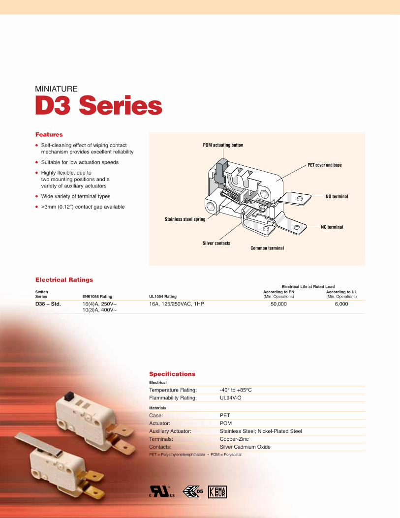
MINIATURE
D3 SeriesFeatures
Self-cleaning effect of wiping contactmechanism provides excellent reliability
Suitable for low actuation speeds
Highly flexible, due to two mounting positions and a variety of auxiliary actuators
Wide variety of terminal types
>3mm (0.12″) contact gap available
SpecificationsElectrical
Temperature Rating: -40° to +85°CFlammability Rating: UL94V-O
Materials
Case: PETActuator: POMAuxiliary Actuator: Stainless Steel; Nickel-Plated SteelTerminals: Copper-ZincContacts: Silver Cadmium OxidePET = Polyethyleneterephthalate • POM = Polyacetal
Stainless steel spring
POM actuating button
PET cover and base
NC terminal
Common terminalSilver contacts
NO terminal
Electrical RatingsElectrical Life at Rated Load
Switch According to EN According to ULSeries EN61058 Rating UL1054 Rating (Min. Operations) (Min. Operations)
D38 – Std. 16(4)A, 250V~ 16A, 125/250VAC, 1HP 50,000 6,00010(3)A, 400V~

35
Code Current Rating
Standard Force
8 16A, 125/250VAC, 1HP (UL, CSA)16(4)A, 250V~; 10(3)A, 400V~ (ENEC)
max
0.6
3 (1
6)
0.52
(13
.1)
0.41
(10.
3)
0.13
(3.2
)
0.11
(2.8
)
0.13(3.4)
1.09(27.8)0.87
(22.2)0.80
(20.25)0.13(3.2)
0.11(2.8)
0.41
(10.
3)
0.16 (4)
NO
NC
Reference Line
Screw
25°
30°
0.51 (13.0)
QC 0.25 x 0.031 (6.3 x 0.8)
QC0.189 x 0.031 (4.8 x 0.8)
0.134 (3.2)0.445 (11.3)
Welding
0.264 (6.7)0.250 (6.3)
Solder
0.264 (6.7)
0.260 (6.60)
Ø0.09 (Ø2.2)
5°8°
0.52 (13.3)
0.260 (6.6)
0.250 (6.3)
Terminals
V3
S8
Q3
A8
W9
D3 8 3 — Q3 L D
Series/Prefix Code Contact Configuration
Standard Operating Force
1 SPST NO2 SPST NC3 SPDT
Light Operating Force
7 SPST NO8 SPST NC9 SPDT
Code Terminal Type inches (mm)
V3 0.25 x 0.031 (6.3 x 0.8) QCQ3 0.189 x 0.031 (4.8 x 0.8) QCS8 Solder with Temp. StopW9 ScrewA8 Welding
Code Actuation Length inches (mm)
Code Actuator Type A D L
AA Button — — —J Straight, Stainless, SR 0.835 (21.2) 1.402 (35.6) 2.752 (69.9)K Straight, Stainless, HR 1.012 (25.7) 1.579 (40.1) 2.929 (74.4)L Straight, SR 0.835 (21.2) 1.402 (35.6) 2.752 (69.9)M Straight, HR 1.012 (25.7) 1.579 (40.1) 2.929 (74.4)R Roller, SR 0.811 (20.6) 1.343 (34.1) —S Simulated Roller, SR 0.811 (20.6) — —T Roller, HR 0.988 (25.1) 1.520 (38.6) —U Simulated Roller, HR 0.988 (25.1) — —
Ordering Information
Dimensions inches (mm)
Actuation Length
Standard Ratio (SR) 0.35 (9.0)
High Ratio (HR) 0.53 (13.5)
Simulated Roller
Roller
Straight
0.20
(5)
NO
NC
NO
NC
0.42
(10
.55)
Auxiliary Actuators
Note: PCB terminals available upon request.
Specifications subject to change without notice.
Actuator SpecificationsMaximum Operating Force (cN) Maximum Operating Minimum Max. Movement Max. Rest Actuation
Pre-Travel Point* Over-Travel Differential Position Length**Actuator Switch inches inches inches inches inches inches
Type Type D38 Std. (mm) (mm) (mm) (mm) (mm) (mm)AA 400 0.059 0.559/0.598 0.047 0.012 0.63 —
(1.5) (14.2/15.2) (1.2) (0.3) (16.0) —MA/KA 265 0.106 0.567/0.630 0.067 0.024 0.71 1.012
(2.7) (14.4/16.0) (1.7) (0.6) (18.0) (25.7)MD/KD 120 0.232 0.528/0.669 0.146 0.051 0.85 1.579
(5.9) (13.4/17.0) (3.7) (1.3) (21.6) (40.1)ML/KL 50 0.528 0.433/0.764 0.335 0.118 1.19 2.929
(13.4) (11.0/19.4) (8.5) (3.0) (30.1) (74.4)LA/JA 425 0.063 0.579/0.618 0.039 0.016 0.66 0.835
(1.6) (14.7/15.7) (1.0) (0.4) (16.8) (21.2)LD/JD 200 0.138 0.551/0.646 0.083 0.031 0.75 1.402
(3.5) (14.0/16.4) (2.1) (0.8) (19.1) (35.6)LL/JL 80 0.311 0.488/0.709 0.193 0.071 0.97 2.752
(7.9) (12.4/18.0) (4.9) (1.8) (24.6) (69.9)*Measured above reference line. Refer to dimensional drawing above. **Actuator tolerance ±0.031 inches (0.8mm).

36
Contact Gap >3mm (0.12 inch)Electrical Ratings
Electrical Life at Rated LoadSwitch According to EN According to ULSeries EN61058 Rating UL1054 Rating (Min. Operations) (Min. Operations)
D36 4(3)A, 250V~ 4A, 250VAC, 1/3HP 50,000 10,000125/250VAC
D37 10(4)A, 250V~ 10A, 1/2HP, 125/250VAC 50,000 6,000D3B 8(8)A, 250V~ 10A, 1/2HP, 125/250VAC 50,000 10,000
D3 7 4 Q3 LD
Series/Prefix Actuator Code
See table aboveCode Contact Configuration
4 SPST NO5 SPST NC (D3B only)
6 SPDT (D3B only)
Code Terminal Type inches (mm)
V1 0.25 x 0.03 (6.3 x 0.8) QC, StraightV3 0.25 x 0.03 (6.3 x 0.8) QC, Dog LegQ1 0.19 x 0.03 (4.8 x 0.8) QC, StraightQ3 0.19 x 0.03 (4.8 x 0.8) QC, Dog LegC1 0.11 x 0.03 (2.8 x 0.8) QC, Bifurcated Straight*C3 0.11 x 0.03 (2.8 x 0.8) QC, Bifurcated Dog Leg*S8 Solder with Temp. StopW9 Screw (D3B only)
A8 Welding
Ordering Information
Terminal Options
Specifications subject to change without notice.
Note: PCB terminals available upon request.*D36 only.
0.44 (11.3)
0.13
(3.
4)
0.52 (13.3)
5°
8°
0.51 (13)
25°
30°
0.26 (6.6)
0.25 (6.3)
)
0.26
(6.
7)
0.26 (6.6)
ø0.09 (ø2.2)
0.26
(6.
7)
0.39 (10.0)
QC 0.25 x 0.03 (6.3 x 0.8)
V1
QC 0.25 x 0.03 (6.3 x 0.8)Dog Leg
V3
QC 0.19 x 0.03 (4.8 x 0.8)Straight
Q1
QC 0.19 x 0.03 (4.8 x 0.8)Dog Leg
Q3
QC 0.11 x 0.03 (2.8 x 0.8)Bifurcated, Straight
C1
Solder
S8
Welding
A8
QC 0.11 x 0.03 (2.8 x 0.8)Bifurcated, Dog Leg
C3
Screw
W9
Code UL Rating EN 61058 Rating
6 4A,1/3HP, 125/250VAC 4(3)A, 250V~7 10A, 1/2HP, 125/250VAC 10(4)A, 250V~B 10A, 1/2HP, 125/250VAC 8(8)A, 250V~
Actuator SpecificationsMaximum Maximum Operating Minimum Max. Movement Max. Rest ActuationOperating Pre-Travel Point* Over-Travel Differential Position Length
Actuator Switch Force inches inches inches inches inches inchesCode Type (cN) (mm) (mm) (mm) (mm) (mm) (mm)AA 500 0.075 0.567±0.020 0.028 0.047 0.63 —
(1.9) (14.4±0.5) (0.7) (1.2) (16.0) —MA/KA 320 0.134 0.579±0.031 0.035 0.079 0.71 1.012
(3.4) (14.7±0.8) (0.9) (2.0) (18.0) (25.7)TA forces and travel available upon request 0.988
(25.1)UA forces and travel available upon request 0.988
(25.1)MD/KD 150 0.295 0.563±0.075 0.075 0.177 0.86 1.579
(7.5) (14.3±1.9) (1.9) (4.5) (21.8) (40.1)TD forces and travel available upon request 1.520
(38.6)KL 65 0.669 0.512±0.165 0.165 0.409 1.21 2.929
(17.0) (13.0±4.2) (4.2) (10.4) (30.8) (74.4)LA/JA 550 0.075 0.587±0.020 0.024 0.047 0.66 0.835
(1.9) (14.9±0.5) (0.6) (1.2) (16.8) (21.2)RA forces and travel available upon request 0.811
(20.6)SA forces and travel available upon request 0.811
(20.6)LD/JD 240 0.177 0.575±0.047 0.047 0.102 0.76 1.402
(4.5) (14.6±1.2) (1.2) (2.6) (19.2) (35.6)RD forces and travel available upon request 1.343
(34.1)JL 100 0.425 0.520±0.110 0.126 0.256 0.098 2.752
(10.8) (13.2±2.8) (3.2) (6.5) (25.0) (69.9)

37
MINIATURE
ESeriesFeatures
8 current ratings AC
3 current ratings DC
Choice of actuator styles
Choice of terminals
3 contact arrangements
Long-life coil spring mechanism
Agency approved extended life versions
High-temperature versions available
SpecificationsElectrical
Temperature Rating: -40° to +85°C (130°C and 150°C optional, except E36)Flammability Rating: UL94HBMaterials
Case: General Purpose PhenolicActuating Button: Thermoplastic AcetalCommon Terminals: Silver-Plated Brass (E21, E22, E23, E31, E33, E34, E35)
Silver-Plated Copper (E36)NO & NC Terminals: Brass (E21, E22, E23, E31, E33, E34, E35)
Copper (E36)Moving Blade: Brass (E21, E22, E23)
Silver-Plated Beryllium Copper (E31, E33, E34, E35, E36)Spring: Stainless Steel Auxiliary Actuator: Cold-Rolled Steel (Nickel-Plated)
(except E21 and E22 — Aluminum)Roller: Sintered Stainless SteelContacts: Silver Alloy (except E21 and E31 — Gold Crosspoint)
Stainless steel spring
Thermoplasticactuating button
Phenolic case
Silver alloy or gold crosspoint contacts
Common terminal
NC terminal
NO terminal
(E34 and E35 only)
Electrical RatingsElectrical Life at Rated Load
Switch According to VDE According to ULSeries EN61058 Rating UL1054 Rating (Min. Operations) (Min. Operations)
E21 N/A 0.1A, 125VAC (0.25A, 30VDC optional) N/A 6,000**E22 N/A 3A, 125/250VAC N/A 6,000
1/10HP, 250VAC (0.1A, 125VDC optional)E23 N/A 5A, 1/4HP, 125/250VAC N/A 6,000E31 N/A 1A, 125VAC N/A 6,000E33 N/A 10A, 1/2HP, 125/250VAC (6A, 30VDC optional) N/A 6,000**E34 N/A 15A, 1/2HP, 125/250VAC N/A 6,000*E35 N/A 20.1A, 1/2HP, 125/250VAC N/A 6,000E36 N/A 25A, 125/250VAC; 1HP, 125VAC N/A 6,000
2HP, 250VAC*Indicates 100K life available for AC version only.**Indicates 100K life available for AC and DC versions.

38
0.406(10.31
0.0150.38)
+-+-
0.250(6.35)
0.250(6.35)
0.125(3.16)
0.020 (0.51) Thk x 0.187 (4.75) WideQ.C. Terminal
0.797(20.24
0.0100.25)
+-+-
0.625(15.88
0.0150.38)
+-+-0.406
(10.31)
1.093(27.76
0.0150.38)
+-+-
0.875 (22.23)
0.110 (2.79)0.122 (3.10) Dia.
0.234(5.94)
0.087(2.21)
0.110(2.79)
0.106 (2.69) Reference Line
0.397(10.08
0.0150.38)
+-+-
0.110 (2.79)0.122 (3.10)
0.120 (3.05)0.132 (3.35)
x
0.110 (2.79)0.465 (11.81)
COM
N.C.
N.O.
0.035(0.89
0.0200.51)
+-+-
0.050(1.27)Dia.
0.109(2.77)
0.750(19.05)Max.Rest
1.382(35.10
0.0310.79)
+-+-
0.580(14.73
0.0451.14)
+-+-Operating Position
ActuationLine
0.960(24.38)Max.Rest
1.289(32.74
0.0310.79)
+-+-
0.786(19.96
0.0451.14)
+-+-Operating Position
ActuationLine
COM
COM
N.C.
N.O.
N.C.
N.O.
Actuator Specifications — Standard ForceMax. Operating Force (gms.) Maximum Operating Minimum Max. Movement Actuation
Pre-Travel Point* Over-Travel Differential Length**Actuator Switch E21, E23, inches inches inches inches inches
Type Type E22 E31 E33 E34 (mm) (mm) (mm) (mm) (mm)–00A 75 170 285 400 0.047 0.578±0.020 0.050 0.010 —
(1.19) (14.68±0.51) (1.27) (0.25) —–00H 75 170 285 400 0.062 0.600±0.020 0.050 0.016 0.865
(1.57) (15.24±0.51) (1.27) (0.41) (21.97)–50H 35 86 144 200 0.125 0.600±0.045 0.085 0.030 1.400
(3.18) (15.24±1.14) (2.16) (0.76) (35.56)–50HL 20 51 86 120 0.220 0.600±0.075 0.130 0.040 1.580
(5.59) (15.24±1.91) (3.30) (1.02) (40.13)–00K 75 170 285 400 0.047 0.806±0.030 0.040 0.010 0.810
(1.19) (20.47±0.76) (1.02) (0.25) (20.57)–50K 35 86 144 200 0.125 0.806±0.045 0.085 0.030 1.340
(3.18) (20.47±1.14) (2.16) (0.76) (34.04)–50KL 25 51 86 120 0.200 0.806±0.075 0.120 0.040 1.516
(5.08) (20.47±1.91) (3.05) (1.02) (38.51)–50P 35 86 144 200 0.125 1.045±0.045 0.085 0.030 1.340
(3.18) (26.54±1.14) (2.16) (0.76) (34.04)–50N† 35 86 144 200 0.175 0.600±0.045 0.065 0.030 1.382
(4.45) (15.24±1.14) (1.65) (0.76) (35.10)–90N† 35 86 144 200 0.125 0.793±0.058 0.085 0.030 1.289
(3.18) (20.14±1.47) (2.16) (0.76) (32.74)*Measured above reference line. Refer to dimensional drawing above. **Actuator tolerance ± 0.031 inches (0.79mm).†Only available with 85°C temperature rating. Note: E35 and E36 not available in standard force. See Miniature E Series Light Force for ordering information. Suffix numbers shown representswitch with 0.187″ (4.75mm) terminals.
Specifications subject to change without notice.
Dimensions — Standard Force inches (mm)
Part Number Suffix –50N
Part Number Suffix –90N
Mounting — Standard ForceRecommended mounting screw size: #4-40 round head. Recommended torqueon screw: 3 inch lbs. max.
Ordering InformationSelect the current rating you need. Com-bine the corresponding Series/Prefix num-ber with the appropriate suffix number forthe switch type, circuitry and terminals yourequire.
Circuitry — Standard ForceContact arrangement available in choice ofsingle pole double throw or single pole singlethrow, either normally open or normallyclosed. In general normally open may bespecified by changing suffix number from 00 to 01 and normally closed by changingsuffix number to 02.
N.C.N.O.
N.C.N.O.
N.C.N.O.
N.C.N.O.
0.234 (5.94)
0.234 (5.94)
0.234 (5.94)
0.234 (5.94)
0.187 (4.75)
0.250 (6.35)
0.099 (2.51)Dia. Hole
Screw
Terminals
Q.C.
Solder
Short Solder
0.240 (6.10)
Terminals — Standard ForceChoice of screw, solder or two quick connect terminals.Note: 0.187″ Quick Connect terminals arestandard. Normally, to order screw terminalsadd 10 to suffix number. To order solder terminals add 20 to suffix number and toorder 0.250″ Q.C. terminals add 40 to suffix number.Terminal SPDT SPST NO SPST NC
QC 0.187″ –00A –01A –02AScrew –10A –11A –12ASolder –20A –21A –22AShort Solder –30A –31A –32AQC 0.250″ –40A –41A –42A
SwitchMounting Hole
Actuation Length
0.177 (4.50) 0.355 (9.02)
StandardRatio
HighRatio
Actuators — Standard ForceMany special forms and lengths of actuatorsare available. Standard type integral hingedlever and roller actuators are available inchoice of 2 mounting positions. Actuationlengths are dimensioned from centerline ofswitch mounting hole as shown.

39
0.406(10.31
0.0150.38)
+-+-
0.250(6.35)
0.250(6.35)
0.125(3.16)
0.020 (0.51) Thk x 0.187 (4.75) WideQ.C. Terminal
0.797(20.24
0.0100.25)
+-+-
0.625(15.88
0.0150.38)
+-+-0.406
(10.31)
1.093(27.76
0.0150.38)
+-+-
0.875 (22.23)
0.343(8.71
0.0150.38)
+-+-
0.550 (13.97
0.0150.38)
+-+-
0.113 (2.87)0.116 (2.95) Dia.
0.234(5.94)
0.087(2.21)
0.109(2.77)
0.106 (2.69) Reference Line
0.397(10.08
0.0150.38)
+-+-
0.112 (2.85)0.116 (2.95) x 0.126 (3.20)
0.109 (2.77)0.291 (7.39)
COM
N.C.
N.O.
0.050(1.27)Dia.
0.207(5.27
0.0150.38)
+-+-
0.109(2.77)
0.750(19.05)Max.Rest
1.382(35.10
0.0310.79)
+-+-
0.580(14.73
0.0451.14)
+-+-Operating Position
ActuationLine
0.960(24.38)Max.Rest
1.289(32.74
0.0310.79)
+-+-
0.786(19.96
0.0451.14)
+-+-Operating Position
ActuationLine
COM
COM
N.C.
N.O.
N.C.
N.O.
Specifications subject to change without notice.
Dimensions — Light Force inches (mm)
Part Number Suffix –50NX
Part Number Suffix –90NX
Mounting — Light ForceRecommended mounting screw size: #4-40 round head. Recommended torqueon screw: 3 inch lbs. max.
Ordering InformationSelect the current rating you need. Com-bine the corresponding Series/Prefix num-ber with the appropriate suffix number forthe switch type, circuitry and terminals yourequire.
Circuitry — Light ForceContact arrangement available in choice ofsingle pole double throw or single pole singlethrow, either normally open or normallyclosed. In general normally open may bespecified by changing suffix number from 00 to 01 and normally closed by changingsuffix number to 02.
N.C.N.O.
N.C.N.O.
N.C.N.O.
N.C.N.O.
0.234 (5.94)
0.234 (5.94)
0.234 (5.94)
0.234 (5.94)
0.187 (4.75)
0.250 (6.35)
0.099 (2.51)Dia. Hole
Screw
Terminals
Q.C.
Solder
Short Solder
0.240 (6.10)
Terminals — Light ForceChoice of screw, solder or two quick connect terminals.Note: 0.187″ Quick Connect terminals arestandard. Normally, to order screw terminalsadd 10 to suffix number. To order solder terminals add 20 to suffix number and toorder 0.250″ Q.C. terminals add 40 to suffix number.Exception: When ordering –55HX, –75HX,–75KX or –85HX switches with screw, solderor 0.250″ terminals, consult factory.Terminal SPDT SPST NO SPST NC
QC 0.187″ –00AX –01AX –02AXScrew –10AX –11AX –12AXSolder –20AX –21AX –22AXShort Solder –30AX –31AX –32AXQC 0.250″ –40AX –41AX –42AX*E35 and E36 only available with 0.250″ (6.35) terminals.
SwitchMounting Hole
Actuation Length
0.177 (4.50) 0.355 (9.02)
StandardRatio
HighRatio
Actuators — Light ForceMany special forms and lengths of actuatorsare available. Standard type integral hingedlever and roller actuators are available inchoice of 2 mounting positions. Actuationlengths are dimensioned from centerline ofswitch mounting hole as shown.
Actuator Specifications — Light ForceMaximum
Max. Operating Force (gms.) Maximum Operating Minimum Movement ActuationPre-Travel Point* Over-Travel Differential Length**
Actuator Switch E21, E23, inches inches inches inches inchesType Type E22 E31 E33 E34 E35 E36 (mm) (mm) (mm) (mm) (mm)
–00AX 15 45 75 100 — — 0.047 0.578±0.020 0.050 0.010 —(1.19) (14.68±0.51) (1.27) (0.25) —
–00HX 15 45 75 100 — — 0.062 0.600±0.020 0.050 0.016 0.865(1.57) (15.24±0.51) (1.27) (0.41) (21.97)
–50HX 8 22 37 50 — — 0.125 0.600±0.045 0.085 0.030 1.400(3.18) (15.24±1.14) (2.16) (0.76) (35.56)
–75HX 5 14 22 30 — — 0.220 0.600±0.075 0.130 0.040 1.580(5.59) (15.24±1.91) (3.30) (1.02) (40.13)
–50KX 8 22 37 50 — — 0.125 0.806±0.045 0.085 0.030 1.340(3.18) (20.47±1.14) (2.16) (0.76) (34.04)
–75KX 5 14 22 30 — — 0.200 0.806±0.075 0.120 0.040 1.516(5.08) (20.47±1.91) (3.05) (1.02) (38.51)
–55HX 4 10 17 22 — — 0.300 0.600±0.100 0.187 0.065 2.757(7.62) (15.24±2.54) (4.75) (1.65) (70.03)
–85HX 2 6 10 13 — — 0.500 0.600±0.175 0.312 0.100 2.932(12.70) (15.24±4.45) (7.92) (2.54) (74.47)
–50NX† 8 22 37 50 65 112 0.175 0.600±0.045 0.065 0.303 1.382(4.45) (15.24±1.14) (1.65) (0.76) (35.10)
–90NX† 8 22 37 50 65 112 0.125 0.793±0.058 0.085 0.030 1.289(3.18) (20.14±1.47) (2.16) (0.76) (32.74)
–40AX — — — — 120 220 0.070 0.557±0.020 0.035 0.010 —(1.78) (14.15±0.51) (0.89) (0.25) —
*Measured above reference line. Refer to dimensional drawing above. **Actuator tolerance ±0.031 inches (0.79mm).†Only available with 85°C temperature rating. Note: Suffix numbers shown represent switch with 0.187″ (4.75mm) terminals.

MINIATURE LOW TORQUE
ESeries
Stainless steel spring
Phenolic case
Silver or gold crosspointcontacts
Brass movingbladeNC terminal
Common terminalNO terminal
Features
Long life coil spring mechanism
Low torque rotary actuation
Clockwise or counter clockwise actuation
6 terminal types
Double rivet sturdy case construction
3 contact arrangements
SpecificationsElectrical
Temperature Rating: -40° to +85°CFlammability Rating: UL94HB
Materials
Case: General Purpose PhenolicTerminal: Silver-Plated BrassMoving Blade: BrassContacts: Silver Alloy (E51), Gold Crosspoint (E53)
Spring: Stainless Steel
Electrical RatingsElectrical Life at Rated Load
Switch According to VDE According to ULSeries EN61058 Rating UL1054 Rating (Min. Operations) (Min. Operations)
E51 N/A 6A, 250VAC N/A 6,000E53 N/A 0.1A, 125VAC N/A 6,000

41
1.218(30.94)
0.937(23.80)
0.709(18.01)
0.483(12.27)
0.065(1.65)
0.293(7.44)
0.388(9.85)
0.328(8.33)
0.139(3.53)
0.685(17.40)
0.265(6.73)
0.123 (3.12)0.126 (3.20)
Dia Hole
0.123 (3.12)0.126 (3.20)
x 0.158(4.01) Slot
0.550(13.97)
0.580(14.73)
0.652 (16.56)
0.750 (19.05)
0.875(22.23)
Max
Mtg Surface0.140 (3.56)
0.343(8.71)
0.218 (5.54)
COM N.O. N.C.
0.032 (0.81)
0.062 x 0.100 Slot (1.58 x 2.54)
0.062 x 0.100 Slot (1.58 x 2.54)
0.062 x 0.100 Slot (1.58 x 2.54)
0.406 (10.31)
0.205 (5.21)
0.020(0.51)
0.020(0.51)
0.406 (10.31)
0.406 (10.31)
0.187 (4.75)
0.032 (0.81)
0.205 (5.21)
0.062 x 0.100 Slot(1.58 x 2.54)
Standard Parallel QC Vertical Twist QC
0.020 (0.51)
0.187 (4.75)
0.205(5.21)
0.093 (2.36)
Dia. Hole
0.312 (7.93) Max
0.032 (7.67)
Vertical Straight QC
0.187(4.75)
Terminals
26° 3°±
Clockwise ActuationCounterclockwise Actuation
Rest from Centerline 26° ± 3°. Full Overtravel 38° minimum.
Datum Line Datum Line
0°
38° min.Total Stroke
RestPos.
Reset Rangeon Return Stroke
5°
13°
21°
15°
SW. OP. Rangeon OP. Stroke
0°
Reset Rangeon Return Stroke
5°
13°
21°
15°
38° min.Total Stroke
OP. Rangeon OP. Stroke
COM N.O. N.C.
Dimensions inches (mm)
Switch Rotor
WireformNo. 0014-0645
3.19(81.03)
Clockwise Actuation Shown
ActuatorsWireform actuators are supplied unassembled for each switch. Wireforms may be readily assembled to switch rotor as shown.
Specifications subject to change without notice.
CircuitryThis series is available in single pole double throw and single pole single throweither normally open or normally closed. Ingeneral, normally open may be specified byadding 01 to suffix numbers, and normallyclosed by adding 02. For example, E51-00B is double throw,E51-01B is normally open and E51-02B is normally closed.
MountingRecommended mounting screw size: #4-40 Round head. Recommended torqueon screw: 4 inch lbs. max.
Operating Characteristics
Standard Force 4.0″ gms. (max.)Overtravel 15° min.
(10.5 gram – cm)Movement Differential 3° min.Note: Special models and tooling capability available for custom wireform actuators.
Note: Additional operating forces available upon request. Consult factory.
Ordering InformationSelect the current rating you need. Com-bine the corresponding Series/Prefix num-ber with the appropriate suffix number forthe switch type, circuitry and terminals yourequire.
Actuator Specifications
Switch Actuator Direction of TerminalsType Type Actuator inches (mm)
–00B Clockwise Standard Parallel 0.205 (5.21)–00R Clockwise Standard Parallel 0.187 (4.75)–00E Counter Clockwise Standard Parallel 0.205 (5.21)–00T Counter Clockwise Standard Parallel 0.187 (4.75)–50B Clockwise Vertical Twist 0.205 (5.21)–50R Clockwise Vertical Twist 0.187 (4.75)–50E Counter Clockwise Vertical Twist 0.205 (5.21)–50T Counter Clockwise Vertical Twist 0.187 (4.75)–60B Clockwise Vertical Straight 0.205 (5.21)–60R Clockwise Vertical Straight 0.187 (4.75)–60E Counter Clockwise Vertical Straight 0.205 (5.21)–60T Counter Clockwise Vertical Straight 0.187 (4.75)

MINIATURE
KSeriesFlame retardant, UL94V-Oself-extinguishing case and cover
Long-life snap actionswitch mechanism
ARC-resistant casehas internal barriers,4mm minimum betweenlive parts and externalhardware
NC terminal
NO terminal
Common terminal
Single or double throw, either normally open or normally closed
Choice of U.S. (#4 screw)or metric (3mm screw)
Features Choice of current ratings up to 25 amps Choice of actuators Choice of terminals 3 contact arrangements Choice of operating force Long mechanical life Wiping contact action Snap over actuators Agency approved extended life versions
International Approved VersionsK Series switches, except 25A (KWS), areinternationally approved. Switches withstraight terminals may require insulatedconnectors for international approval.
SpecificationsElectrical
Temperature Rating: -40° to +85°C, 150°C or 200°CFlammability Rating: UL94V-O
Materials
Case/Cover: Thermoplastic Polyester (85°C or 150°C)Liquid Crystal Polymer (200°C)
Button: Thermoplastic Acetal (85°C)Thermoplastic Polyester (150°C)Liquid Crystal Polymer (200°C)
Auxiliary Actuator: Cold-Rolled Steel (Nickel-Plated)Terminals: Brass
Copper (25 amp only)Moving Blade: Beryllium CopperContacts: Silver Alloy (except KWA and KWB — Gold-Plated)
Electrical RatingsElectrical Life at Rated Load
Switch According to VDE According to ULSeries EN61058 Rating UL1054 Rating (Min. Operations) (Min. Operations)
KWA/KWB 50mA, 28VDC 50mA, 28VDC 50,000 100,000KWC/KWD 1(0.5)A, 250VAC 1.0A, 125/250VAC 50,000 100,000KWE/KWF 3(1)A, 250VAC 3A, 1/10HP, 125/250VAC 50,000 100,000KWG/KWH 6(2)A, 250VAC 5A, 1/4HP, 125/250VAC 50,000 100,000KWJ/KWK 10(3)A, 250VAC 10A, 1/2HP, 125/250VAC 50,000 100,000KWL N/A 15.1A, 1/2HP, 125/250 VAC N/A 100,000
5A, 125VAC Lamp Load (85°C only)0.5A, 125VDC (85°C only)0.25A, 250VDC (85°C only)
KWM 16(4)A, 250VAC 15.1A, 1/2HP, 125/250VAC 50,000 100,0000.5A, 125VDC (85°C and 150°C only)0.25A, 250VDC (85°C and 150°C only)
15.1A, 1/2HP, 125/250VAC (200°C only)KWS N/A 25A, 125/250VAC (85°C only) N/A 100,000
1HP, 125VAC (85°C only)2HP, 250VAC (85°C only)

43Specifications subject to change without notice.
KW A D Q A C A
1.140(28.96)
0.406(10.31)
0.160(4.06)
0.625(15.88)
0.368(9.35)
0.032 (0.81) or0.020 (0.51)0.570
(14.48)
Dog Leg Terminal
0.174* (4.42) or0.125 (3.18)
0.250* (6.35) or0.187 (4.75)Ø 0.070 (1.78)
0.057 (1.45)
0.236(5.99)
0.282 (7.16)
0.360(9.14)
0.875 ± 0.005(22.23 ± 0.13)Ø B ± 0.005
(± 0.13)
NC
NO
COM
0.112 (2.85)
0.156(3.96)
0.119(3.02)
0.570(14.48)
0.797(20.24)
0.532(13.51)
0.109(2.77)
0.578 ± 0.015(14.68 ± 0.38)
Oper. Pos. 0.406 ± 0.005(10.31 ± 0.13)
A ± 0.005(±0.13)
ØA ± 0.005(± 0.13)
0.109(2.77)
0.047(1.19) Max.
Pretravel
Ref. Line
A Dim. 0.114 (2.90) 0.122 (3.10)B Dim. 0.126 (3.20) 0.134 (3.40)Mtg Screw 4-40 (3)
Mounting Holes
Notes:SPDT switch (as shown) with 3 terminals NO, NC, and COM. SPST switch will have one terminal (NO or NC), and a COMMON terminal depending on switch type.
0.320(8.13)
U.S. Metric
*Applicable to 0.032 (0.8) thick by 0.250 (6.3) wide tabs only.
Series/Prefix
Light Standard Current
Code Force Code Force Rating Notes
A 25 B 75 50mA 1C 25 D 75 1A 1E 25 F 75 3A 1G 50 H 150 5A 1J 75 K 150 10A 1
L 150 15A 3M 150 15A 2S 225 25A 3, 5
Code Temperature Rating
A 85°C UL/CULB 150°C UL/CULC 200°C UL/CULD 85°C UL/CUL/VDE*E 150°C UL/CUL/VDE
Code Terminal Type inches (mm)
P4 0.062 x 0.032 (1.57 x 0.81) PCB*Q 0.187 x 0.020 (4.75 x 0.51) StraightR 0.187 x 0.020 (4.75 x 0.51) Dog LegS 0.187 x 0.032 (4.75 x 0.81) StraightT 0.187 x 0.032 (4.75 x 0.81) Dog LegV 0.250 x 0.032 (6.35 x 0.81) StraightW 0.250 x 0.032 (6.35 x 0.81) Dog Leg
Code Mounting Holes
A U.S.B Metric
Code Configuration
A Normally OpenB Normally ClosedC Double Throw
Snap Over Actuators
Actuation Length Code Type inches (mm)
A ButtonB Straight SR 0.865 (21.97)C Straight SR 1.400 (35.56)D Straight SR 2.722 (69.14)E Straight HR 1.077 (27.36)F Straight HR 1.612 (40.95)G Straight HR 2.934 (74.52)J SIM Roller SR 1.254 (31.85)M SIM Roller HR 1.466 (37.24)Y† Roller SR 0.810 (20.57)Q Roller SR 1.340 (34.04)W† Roller HR 1.022 (25.96)T Roller HR 1.552 (39.42)
Ordering Information
Auxiliary Actuator
Dimensions inches (mm)
Actuation Length Straight
Roller
SimulatedRoller
High Ratio Standard Ratio
0.532(13.51)
0.320(8.13)
ActuatorsStandard type snap over hinged lever and roller actuators are available in choice of two pivot positions. Lengths are dimensioned from centerline of switch upper mounting hole as shown here.
*PCB terminals are lateral to case only.
*Only available with 15A.
†Available as internal mounting only.
Notes:1. CULUS rated for 100,000 cycles at 85°C,
150°C, 200°C. VDE rated for 150°C only.2. CULUS rated for 100,000 cycles at 85°C,
150°C, 200°C. VDE rated for 85°C only.3. CULUS rated for 100,000 cycles at 85°C only.4. Available in 10A and lower, CULUS rated
for 100,000 cycles at 85°C and 150°C.5. Available with 0.250 x 0.032″ terminals only.
MountingRecommended mounting screw size: #4-40 Round head. Recommended torqueon screw: 3 inch lbs. max.
Actuator SpecificationsMaximum Operating Force (gms.) Maximum Operating Minimum Max. Movement Actuation
Pre-Travel Point* Over-Travel Differential Length**Actuator Switch KWA, KWD, KWJ KWH, inches inches inches inches inches
Type Type KWC, KWE KWG KWB, KWF KWK, KWM KWS (mm) (mm) (mm) (mm) (mm)A 25 50 75 150 225 0.047 0.563/0.593 0.050 0.010 —
(1.19) (14.31/15.06) (1.27) (0.25) —B 25 50 75 150 225 0.064 0.621/0.585 0.051 0.012 0.865
(1.63) (15.78/14.85) (1.29) (0.31) (21.97)C 14 27 40 80 120 0.128 0.637/0.569 0.085 0.030 1.400
(3.26) (16.18/14.45) (2.16) (0.76) (35.56)D 6 12 18 36 54 0.284 0.679/0.527 0.182 0.051 2.722
(7.22) (17.25/13.38) (4.62) (1.30) (69.14)E 15 30 44 88 132 0.116 0.634/0.572 0.074 0.021 1.077
(2.95) (16.11/14.52) (1.88) (0.54) (27.36)F 8 15 23 45 67 0.230 0.665/0.541 0.146 0.041 1.612
(5.85) (16.90/13.74) (3.71) (1.05) (40.94)G 4 7 10 20 30 0.512 0.739/0.467 0.407 0.091 2.934
(13.01) (18.78/11.86) (10.33) (2.32) (74.52)J 16 31 46 92 138 0.110 0.758/0.698 0.088 0.020 1.254
(2.80) (19.26/17.72) (2.23) (0.51) (31.85)M 9 18 26 52 77 0.200 0.781/0.675 0.115 0.036 1.466
(5.08) (19.84/17.14) (2.92) (0.92) (37.24)Q 15 29 43 85 127 0.120 0.852/0.786 0.096 0.022 1.340
(3.05) (21.65/19.96) (2.43) (0.56) (34.04)T 8 16 24 47 71 0.218 0.877/0.761 0.173 0.039 1.552
(5.54) (22.28/19.32) (4.39) (1.00) (39.42)*Measured above reference line. Refer to dimensional drawing above. **Actuator tolerance ±.0.031 inches (0.79mm).

Insert moldedterminal pins
Polished brass screws and lock washers(solder terminals optional)
Gold over silver contacts for versatile, long-life switching
High-strengthberyllium copper
alloy spring
Rugged phenoliccase and cover
Features
Ultra-small travel differential
Mechanical life tested to 1 million cycles
Current switching to 20 amps
Wide variety of actuators
Screw or solder terminals standard
Low operating forces available
Specifications
Dielectric Strength: 1000VAC 50/60Hz for 1 minuteInsulation Resistance: 100M ohms min at 500VDCInitial Contact Resistance: 15m ohms maxTemperature Range: -20° to +85°C
Materials
Case: PhenolicCover: PhenolicSpring: Beryllium Copper AlloyContacts: Silver AlloyTerminals: Brass Screw Terminals; Copper Alloy Solder TerminalsLever Actuator: Stainless Steel
HEAVY-DUTY SNAP ACTION
GPSeries
Electrical Ratings
Switch Series UL1054 Rating
GP*B 20A, 1HP, 125VAC; 20A, 2HP, 250VAC; .5A, 125VDC; .25A, 250VDCGP*C 15A, 1/8HP, 125VAC; 15A, 1/4HP, 250VAC; .5A, 125VDC; .25A, 250VDC

45
Terminal Types inches (mm) Mounting Holes
0.921±0.012(23.4±0.3)
1.953(49.6)
1.00±0.004(25.4±0.1) 0.693
(17.6)
ø0.091 (ø2.3)
PT
OP
1.945±0.032(49.4±0.8)
1.953(49.6)
1.00±0.004(25.4±0.1)
±0.008(17.6±0.2)
0.693
0.189(4.8)
0.476(12.1)
0.024(0.6)
FP OP
t=
0.925(23.5)
+-0.0080.2)+-(17.6
1.783±0.031(45.3±0.8)
1.953(49.6)
1.00±0.004(25.4±0.1)
0.693±0.008(17.6±0.2)
ø0.374x0.157(ø9.5x4.0)
0.476(12.1)
0.0240.6)FP OP
t=
N.O.
N.C.COM.
Screw Terminal Solder Terminal
0.787(20.0)
0.787(20.0)
1.937(49.2)
0.36
(9.1
4)
3-M4 x 4.9
3-M2.5x4
1.586(40.3)
0.25
(6.4
)0.
314
(8.0
)
1.937(49.2)
U.S. Version
Metric Version
0.1720.140±0.002
0.001±
4.4±0.10 0.00
0.140 0.003 0.001+-
0.140 0.003 0.001+-
Specifications subject to change without notice.
NOTE: GP Series switches are available with screw or solder terminals in U.S. or metric sizes.*For solder terminals, replace the “T” in the third position of the part number with an “S” (e.g., GPTCND11 becomes GPSCND11).†For metric mounting, replace the “1” in the seventh position with a “0” (e.g., GPTCND11 becomes GPTCND01).
Standard Part Numbers and DescriptionsMaximum Minimum Maximum Operating Minimum Max. MovementOperating Release Pre-Travel Point Over-Travel Differential
Part Force Force inches Min./Max. inches inches Mounting TerminalDimensions inches (mm) Number (oz.) (oz.) (mm) inches (mm) (mm) (mm) Hole† Type*
GPTCNA11 12.3 4.0 0.016 0.610/0.642 0.005 0.002 U.S. Screw(0.41) (15.49/16.31) (0.13) (0.05)
GPTBNA11 22.2 7.1 0.051 0.625/0.657 0.009 0.008 U.S. Screw(1.30) (15.90/16.70) (0.25) (0.20)
GPTCLR11 10.5 1.7 0.157 0.654/0.717 0.062 0.051 U.S. Screw(4.00) (16.60/18.20) (1.60) (1.30)
GPTBLR11 9.0 0.98 0.157 0.654/0.717 0.062 0.067 U.S. Screw(4.00) (16.60/18.20) (1.60) (1.70)
GPTCRR11 10.6 1.8 0.157 1.094/1.157 0.062 0.051 U.S. Screw(4.00) (27.80/29.40) (1.60) (1.30)
GPTBRR11 9.0 0.98 0.157 1.094/1.157 0.062 0.067 U.S. Screw(4.00) (27.80/29.40) (1.60) (1.70)

46 Specifications subject to change without notice.
0.921±0.012(23.4±0.3)
1.953(49.6)
1.00±0.004(25.4±0.1)
0.693±0.008(17.6±0.2)
ø0.157 (ø4.0)
OP
PT
0.476(12.1)
0.921±0.012(23.4±0.3)
1.953(49.6)
1.00±0.004(25.4±0.1)
0.693±0.008(17.6±0.2)
ø0.287 (ø7.3)
OP
PT
0.476(12.1)
1.00±0.004(25.4±0.1) 0.693±0.008
(17.6±0.2)
PT
OP
0.476(12.1)
0.642(16.3)
0.516(13.1)
0.921±0.012(23.4±0.3) 0.327
(8.3)
1.953(49.6)
M (12xP1.0)
1.953(49.6)
1.00±0.004(25.4±0.1) 0.693±0.008
(17.6±0.2)
PT
OP
0.476(12.1)
0.642(16.3)
0.610(15.5)
0.921±0.012(23.4±0.3)
ø0.5x0.150(ø12.7x3.8)
M (12xP1.0)
1.953(49.6)
1.00±0.004(25.4±0.1) 0.693±0.008
(17.6±0.2)
PT
OP
0.476(12.1)
0.642(16.3)
0.610(15.5)
0.906±0.012(23.0±0.3)
ø0.500x0.150(ø12.7x3.8)
(M 12.0xP1.0)
Standard Part Numbers and DescriptionsMaximum Minimum Maximum Operating Minimum Max. MovementOperating Release Pre-Travel Point Over-Travel Differential
Part Force Force inches Min./Max. inches inches Mounting TerminalDimensions inches (mm) Number (oz.) (oz.) (mm) inches (mm) (mm) (mm) Hole† Type*
GPTCND11 12.3 4.0 0.016 1.09/1.13 0.063 0.002 U.S. Screw(0.41) (27.70/28.70) (1.60) (0.05)
GPTBND11 22.9 7.1 0.028 1.091/1.130 0.062 0.008 U.S. Screw(0.70) (27.70/28.70) (1.60) (0.20)
GPTCNC11 12.3 4.0 0.106 0.826/0.866 0.062 0.002 U.S. Screw(0.40) (21.00/22.00) (1.60) (0.05)
GPTBNC11 22.9 7.1 0.028 0.826/0.866 0.062 0.008 U.S. Screw(0.70) (21.00/22.00) (1.60) (0.20)
GPTCNH11 12.3 4.0 0.016 0.826/0.890 0.217 0.002 U.S. Screw(0.41) (20.98/22.60) (5.51) (0.05)
GPTBNH11 22.9 7.1 0.028 0.826/0.890 0.217 0.008 U.S. Screw(0.70) (21.00/22.60) (5.50) (0.20)
GPTCRH11 12.3 4.0 0.016 1.268/1.362 0.140 0.002 U.S. Screw(0.40) (32.20/34.60) (3.58) (0.05)
GPTBRH11 22.9 7.1 0.028 1.268/1.362 0.140 0.008 U.S. Screw(0.70) (32.20/34.60) (3.56) (0.20)
GPTCRH12 12.3 4.0 0.160 1.268/1.362 0.140 0.002 U.S. Screw(0.40) (32.20/34.60) (3.56) (0.05)
GPTBRH12 22.9 7.1 0.028 1.268/1.362 0.140 0.008 U.S. Screw(0.70) (32.20/34.60) (3.56) (0.20)
NOTE: GP Series switches are available with screw or solder terminals in U.S. or metric sizes.*For solder terminals, replace the “T” in the third position of the part number with an “S” (e.g., GPTCND11 becomes GPSCND11).†For metric mounting, replace the “1” in the seventh position with a “0” (e.g., GPTCND11 becomes GPTCND01).

47Specifications subject to change without notice.
OPFP
0.795(20.2)
1.024(26.0)
0.677(17.2)
R 2.5(R 63.5)
1.953(49.6)
1.00±0.004(25.4±0.1) 0.476
(12.1)
0.193(4.9)
0.039(1.0)
t=
0.693±0.008(17.6±0.2)
0.547(13.9)
OPFP
0.795(20.2)
1.024(26.0)
0.677(17.2)
R 1.654(R 42)
1.953(49.6)
1.00±0.004(25.4±0.1) 0.476
(12.1)
0.693±0.008(17.6±0.2)
0.547(13.9)
0.193(4.9)
0.039(1.0)t=
OP
FP
1.024(26.0)
ø0.374x0.157(ø9.5x4.0)
R 1.909
(R 48.5)
0.693±0.008(17.6±0.2)
0.795(20.2)
0.677(17.2)
1.953(49.6)
1.00±0.004(25.4±0.1)
0.476(12.1)
0.547(13.9)
OP
FP
0.693±0.008(17.6±0.2)
0.547(13.9)
0.795(20.2)
1.024(26.0) ø0.374x0.157
(ø9.5x4.0)
0.677(17.2)
R 1.047
(R 26.6)
1.953(49.6)
1.00±0.004(25.4±0.1)
0.476(12.1)
Operating direction
0.547(13.9)
1.953(49.6)
1.00±0.004(25.4±0.1) 0.693±0.008
(17.6±0.2)
FP
OP0.795(20.2)
1.024(26.0)
ø0.374x0.157(ø9.5x4.0)
0.677(17.2)
R 0.437(R 11.1)
R 1.0
47(R
31.9)
0.476(12.1)
Standard Part Numbers and DescriptionsMaximum Minimum Maximum Operating Minimum Max. MovementOperating Release Pre-Travel Point Over-Travel Differential
Part Force Force inches Min./Max. inches inches Mounting TerminalDimensions inches (mm) Number (oz.) (oz.) (mm) inches (mm) (mm) (mm) Hole† Type*
GPTCLS11 2.4 0.50 0.394 0.716/0.780 0.220 0.050 U.S. Screw(10.00) (18.20/19.80) (5.61) (1.27)
GPTBLS11 2.8 0.50 0.394 0.716/0.780 0.220 0.007 U.S. Screw(10.00) (18.20/19.80) (5.61) (0.20)
GPTCLS12 3.1 0.70 0.315 0.716/0.780 0.125 0.040 U.S. Screw(8.00) (18.20/19.80) (3.20) (1.02)
GPTBLS12 4.2 1.4 0.315 0.716/0.780 0.125 0.040 U.S. Screw(8.00) (18.20/19.80) (3.20) (1.02)
GPTCRS11 3.5 0.80 0.280 1.157/1.220 0.158 0.040 U.S. Screw(7.10) (29.40/31.00) (4.00) (1.02)
GPTBRS11 4.2 0.80 0.280 1.157/1.220 0.158 0.040 U.S. Screw(7.10) (29.40/31.00) (4.00) (1.02)
GPTCRM11 5.6 1.4 0.106 1.173/1.205 0.094 0.020 U.S. Screw(2.70) (29.80/30.60) (2.40) (0.50)
GPTBRM11 6.4 1.5 0.106 1.173/1.205 0.094 0.020 U.S. Screw(2.70) (29.80/30.60) (2.40) (0.50)
GPTCRG11 5.6 1.4 0.106 1.594/1.658 0.094 0.020 U.S. Screw(2.70) (40.50/42.10) (2.40) (0.50)
GPTBRG11 6.3 1.4 0.106 1.594/1.658 0.094 0.020 U.S. Screw(2.70) (40.50/42.10) (2.40) (0.50)
NOTE: GP Series switches are available with screw or solder terminals in U.S. or metric sizes.*For solder terminals, replace the “T” in the third position of the part number with an “S” (e.g., GPTCND11 becomes GPSCND11).†For metric mounting, replace the “1” in the seventh position with a “0” (e.g., GPTCND11 becomes GPTCND01).

GENERAL PURPOSE — SINGLE & DOUBLE POLE
ESeriesStainless steel springs
Thermoplastic actuating button
Phenolic case
Silver alloy, silver-cadmium oxide or gold crosspoint contacts
Common terminals
NC terminal
Brass moving blades
NC terminal
NO terminal
NO terminal
Features 5 current ratings Choice of actuator styles 3 terminal types (optional screw
terminals available — consult factory) 3 contact arrangements Long-life coil spring mechanism High-temperature 150°C and 200°C
available on select models (consult factory)
SpecificationsElectrical
Temperature Rating: 105°C Std. (150°C and 200°C optional — E13, E14, E19, E20, G13)85°C Std. (E28 and E29), 85°C Std. (150°C optional) E25
Flammability Rating: UL94HB
Materials
Case: General Purpose PhenolicActuating Button: Thermoplastic NylonCommon Terminals: Brass (E13, E19, E19A, G13, G20)
Silver-Plated Brass (E14, E20, E28, E29, E30)NO and NC Terminals: Brass (E13, E19, E19A, G13, G20)
Copper (E14, E20, E28, E29, E30)Moving Blade: Brass (E13, E19, E19A, G13, G20)
Silver-Plated Beryllium Copper (E14, E20, E28, E29, E30)Spring: Stainless SteelAuxiliary Actuators: Cold-Rolled Steel (Nickel-Plated)Roller: Sintered Stainless SteelContacts: Gold Crosspoint (G13, G20, E19A)
Silver-Cadmium Oxide (E13, E14, E19, E20, E28)Silver Alloy (E19A, E29, E30)
(E25 only)
Electrical RatingsElectrical Life at Rated Load
Switch According to VDE According to ULSeries EN61058 Rating UL1054 Rating (Min. Operations) (Min. Operations)
E13/E19 N/A 15A, 125/250VAC; 3/4HP, 125VAC N/A 6,000*1-1/2HP, 250VAC
E19A N/A 15A, 125/250VAC; 0.1A, 125VAC N/A 6,000(mixed ratings)
E14/E25 N/A 25A, 125/250VAC; 1HP, 125VAC N/A 6,0002HP, 250VAC
E20 N/A 20A, 125/250VAC; 1HP, 125VAC N/A 6,0002HP, 250VAC
E28/E29 N/A 30.1A, 125/250/277VAC N/A 6,000(UL Approved Only — Resistive Load Only)
E30 N/A 30.1A, 125/250VAC; 1HP, 125VAC N/A 6,0002HP, 250VAC
G13/G20 N/A 0.1A, 125VAC N/A 6,000**Indicates 100K life available.
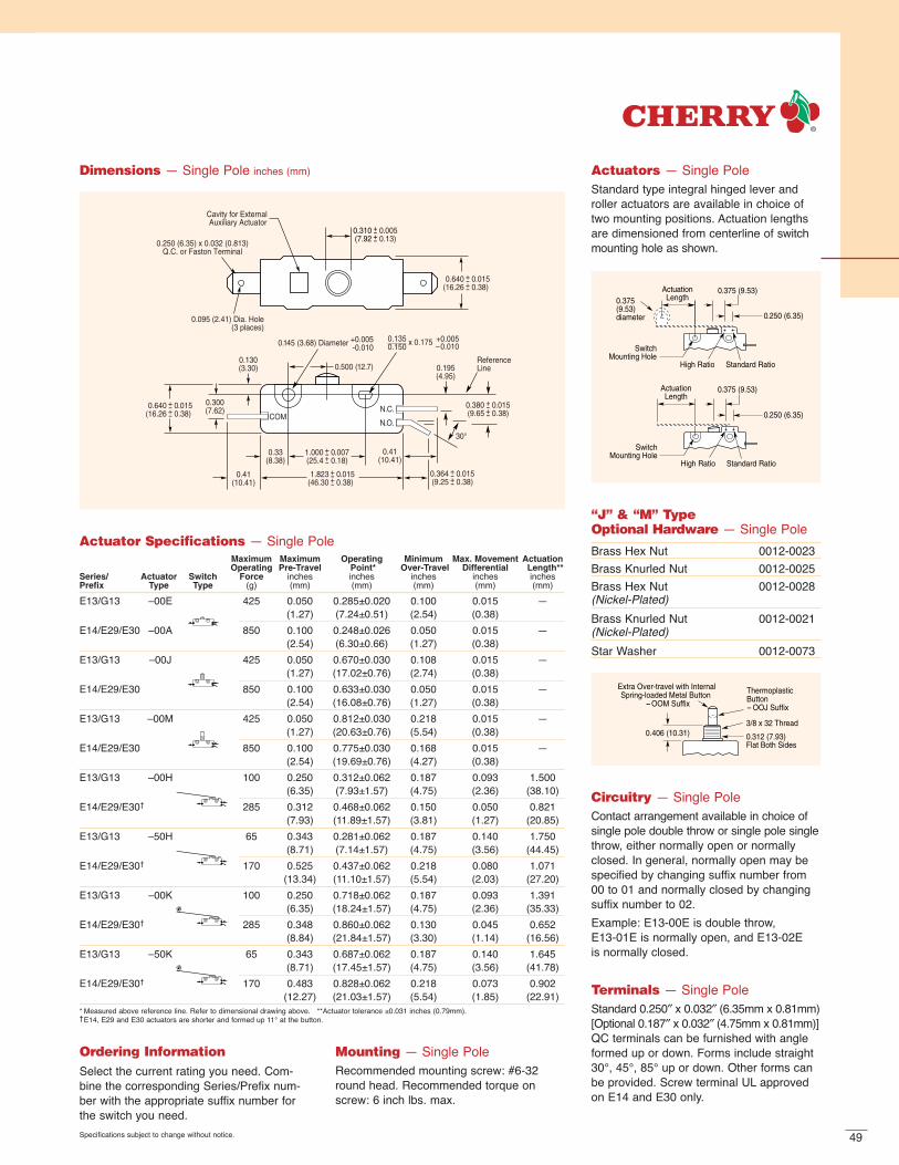
49
0.500 (12.7)
0.41(10.41)
0.41(10.41)
0.33(8.38)
0.300(7.62)
0.130(3.30)
30°
0.250 (6.35) x 0.032 (0.813)Q.C. or Faston Terminal
0.095 (2.41) Dia. Hole(3 places)
1.823(46.30
0.0150.38)
+-+-
1.000(25.4
0.0070.18)
+-+-
0.640(16.26
0.0150.38)
+-+-
ReferenceLine0.195
(4.95)
0.310(7.92
0.0050.13)
+-+-
0.640(16.26
0.0150.38)
+-+-
0.364(9.25
0.0150.38)
+-+-
COMN.O.
N.C. 0.380(9.65
0.0150.38)
+-+-
0.145 (3.68) Diameter +0.005-0.010
0.135 x 0.175 0.150
Cavity for External Auxiliary Actuator
+0.005–0.010
Dimensions — Single Pole inches (mm)
ActuationLength0.375
(9.53)diameter
ActuationLength
SwitchMounting Hole
High Ratio Standard Ratio
0.375 (9.53)
0.375 (9.53)
0.250 (6.35)
0.250 (6.35)
SwitchMounting Hole
High Ratio Standard Ratio
Actuators — Single PoleStandard type integral hinged lever androller actuators are available in choice oftwo mounting positions. Actuation lengths are dimensioned from centerline of switchmounting hole as shown.
0.406 (10.31) 0.312 (7.93) Flat Both Sides
3/8 x 32 Thread
Thermoplastic Button- OOJ Suffix
Extra Over-travel with Internal Spring-loaded Metal Button
- OOM Suffix
“J” & “M” Type Optional Hardware — Single PoleBrass Hex Nut 0012-0023Brass Knurled Nut 0012-0025Brass Hex Nut 0012-0028(Nickel-Plated)
Brass Knurled Nut 0012-0021 (Nickel-Plated)
Star Washer 0012-0073
Specifications subject to change without notice.
Ordering InformationSelect the current rating you need. Com-bine the corresponding Series/Prefix num-ber with the appropriate suffix number forthe switch you need.
Circuitry — Single PoleContact arrangement available in choice ofsingle pole double throw or single pole singlethrow, either normally open or normallyclosed. In general, normally open may bespecified by changing suffix number from00 to 01 and normally closed by changingsuffix number to 02. Example: E13-00E is double throw, E13-01E is normally open, and E13-02E is normally closed.
Mounting — Single PoleRecommended mounting screw: #6-32round head. Recommended torque onscrew: 6 inch lbs. max.
Terminals — Single PoleStandard 0.250″ x 0.032″ (6.35mm x 0.81mm)[Optional 0.187″ x 0.032″ (4.75mm x 0.81mm)]QC terminals can be furnished with angleformed up or down. Forms include straight30°, 45°, 85° up or down. Other forms canbe provided. Screw terminal UL approvedon E14 and E30 only.
Actuator Specifications — Single PoleMaximum Maximum Operating Minimum Max. Movement ActuationOperating Pre-Travel Point* Over-Travel Differential Length**
Series/ Actuator Switch Force inches inches inches inches inchesPrefix Type Type (g) (mm) (mm) (mm) (mm) (mm)
E13/G13 –00E 425 0.050 0.285±0.020 0.100 0.015 —(1.27) (7.24±0.51) (2.54) (0.38)
E14/E29/E30 –00A 850 0.100 0.248±0.026 0.050 0.015 —(2.54) (6.30±0.66) (1.27) (0.38)
E13/G13 –00J 425 0.050 0.670±0.030 0.108 0.015 —(1.27) (17.02±0.76) (2.74) (0.38)
E14/E29/E30 850 0.100 0.633±0.030 0.050 0.015 —(2.54) (16.08±0.76) (1.27) (0.38)
E13/G13 –00M 425 0.050 0.812±0.030 0.218 0.015 —(1.27) (20.63±0.76) (5.54) (0.38)
E14/E29/E30 850 0.100 0.775±0.030 0.168 0.015 —(2.54) (19.69±0.76) (4.27) (0.38)
E13/G13 –00H 100 0.250 0.312±0.062 0.187 0.093 1.500(6.35) (7.93±1.57) (4.75) (2.36) (38.10)
E14/E29/E30† 285 0.312 0.468±0.062 0.150 0.050 0.821(7.93) (11.89±1.57) (3.81) (1.27) (20.85)
E13/G13 –50H 65 0.343 0.281±0.062 0.187 0.140 1.750(8.71) (7.14±1.57) (4.75) (3.56) (44.45)
E14/E29/E30† 170 0.525 0.437±0.062 0.218 0.080 1.071(13.34) (11.10±1.57) (5.54) (2.03) (27.20)
E13/G13 –00K 100 0.250 0.718±0.062 0.187 0.093 1.391(6.35) (18.24±1.57) (4.75) (2.36) (35.33)
E14/E29/E30† 285 0.348 0.860±0.062 0.130 0.045 0.652(8.84) (21.84±1.57) (3.30) (1.14) (16.56)
E13/G13 –50K 65 0.343 0.687±0.062 0.187 0.140 1.645(8.71) (17.45±1.57) (4.75) (3.56) (41.78)
E14/E29/E30† 170 0.483 0.828±0.062 0.218 0.073 0.902(12.27) (21.03±1.57) (5.54) (1.85) (22.91)
* Measured above reference line. Refer to dimensional drawing above. **Actuator tolerance ±0.031 inches (0.79mm).†E14, E29 and E30 actuators are shorter and formed up 11° at the button.

50
0.500(12.7)
0.330(8.38)
30°(2 places)
Reference Line
Cavity for Aux.External Actuator
0.095 (2.41) Dia Hole(6 Places)
0.250 (6.35) x 0.032 (0.81) Thk. Quick Connect Terminal (6 places)
0.145 (3.68)
0.130(3.30)
0.641(16.28
0.0150.38)
+-+-
0.195(4.95
0.0150.38)
+-+-
0.380(9.65
0.0150.38)
+-+-
0.786(19.96
0.0150.38)
+-+-
0.601(15.27
0.0150.38)
+-+-
0.36(9.14
0.0150.38)
+-+-
0.406(10.31
0.0150.38)
+-+-1.813
(46.050.0150.38)
+-+-
0.406(10.31
0.0150.38)
+-+-1.000(25.4
0.0070.18)
+-+-
0.706(17.93
0.0150.38)
+-+-
1.125(28.58
0.0150.38)
+-+-
0.300(7.62
0.0150.38)
+-+-
N.C.
N.O.
N.C.
N.O.
COM
COM
+0.005–0.010
0.135 x 0.175 0.150
+0.005–0.010
Note: With respect to operatingsequence, pole 1 or 2 may operatefirst (virtually same time). If pole1 or 2 must always operate in a particular sequence (1 before 2 or 2 before 1), consult factory.
Dimensions — Double Pole inches (mm)
ActuationLength0.375
(9.53)Diameter
ActuationLength
SwitchMounting Hole
High Ratio Standard Ratio
0.375 (9.53)
0.375 (9.53)
0.250 (6.35)
0.250 (6.35)
SwitchMounting Hole
High Ratio Standard Ratio
Actuators — Double PoleStandard type integral hinged lever androller actuators are available in choice oftwo mounting positions. Actuation lengths are dimensioned from centerline of switchmounting hole as shown.
0.406 (10.31) 0.312 (7.93) Flat Both Sides
3/8 x 32 Thread
Thermoplastic Button- OOJ Suffix
Extra Over-travel with Internal Spring-loaded Metal Button
- OOM Suffix
“J” & “M” Type Optional Hardware — Double PoleBrass Hex Nut 0012-0023Brass Knurled Nut 0012-0025Brass Hex Nut 0012-0028(Nickel-Plated)
Brass Knurled Nut 0012-0021 (Nickel-Plated)
Star Washer 0012-0073
Specifications subject to change without notice.
Ordering InformationSelect the current rating you need. Combinethe corresponding Series/Prefix numberwith the appropriate suffix number for theswitch you need. Note: Consult factory forpart number when ordering E19A switches.
Mounting — Double PoleRecommended mounting screw: #6-32round head. Recommended torque onscrew: 6 inch lbs. max.
Circuitry — Double PoleContact arrangement available in choice ofsingle pole double throw or single pole singlethrow, either normally open or normallyclosed. In general, normally open may bespecified by changing suffix number from00 to 01 and normally closed by changingsuffix number to 02. Example: E19-00A is double throw, E19-01A is normally open, and E19-02Ais normally closed.
Terminals — Double PoleStandard 0.250″ x 0.032″ (6.35mm x 0.81mm)[Optional 0.187″ x 0.032″ (4.75mm x 0.81mm)]QC terminals can be furnished with angleformed up or down on common as well asopen or closed terminal. Forms includestraight 30°, 45°, 85° up or down. Otherforms can be provided.
Actuator Specifications — Double PoleMaximum Maximum Operating Minimum Max. Movement ActuationOperating Pretravel Point* Overtravel Differential Length
Series/ Actuator Switch Force inches inches inches inches inchesPrefix Type Type (g) (mm) (mm) (mm) (mm) (mm)E19/G20 –00A 850 0.050 0.285±0.030 0.080 0.015 —
(1.27) (7.24±0.76) (2.03) (0.38)E20/E28 1280 0.100 0.248±0.030 0.050 0.015 —
(2.54) (6.30±0.76) (1.27) (0.38)E19/G20 –-00J 850 0.050 0.670±0.030 0.080 0.015 —
(1.27) (17.02±0.76) (2.03) (0.38)E20/E28† 1280 0.100 0.630±0.030 0.050 0.015 —
(2.54) (16.00±0.76) (1.27) (0.38)E19/G20 –00M 850 0.050 0.812±0.030 0.218 0.015 —
(1.27) (20.62±0.76) (5.54) (.038)E20/E28† 1280 0.100 0.774±0.030 0.188 0.015 —
(2.54) (19.66±0.76) (4.78) (0.38)E19/G20 –00H 205 0.275 0.312±0.062 0.187 0.093 1.500
(6.99) (7.92±1.57) (4.75) (2.36) (38.10)E20/E28† 425 0.330 0.468±0.062 0.156 0.050 0.821
(8.38) (11.89±1.57) (3.96) (1.27) (20.85)E19/G20 –50H 130 0.400 0.281±0.062 0.187 0.140 1.750
(10.16) (7.14±1.57) (4.75) (3.56) (44.45)E20/E28† 285 0.600 0.437±0.062 0.156 0.080 1.071
(15.24) (11.10±1.57) (3.96) (2.03) (27.20)E19/G20 –00K 212 0.250 0.718±0.062 0.187 0.093 1.391
(6.35) (18.24±1.57) (4.75) (2.36) (35.33)E20/E28† 425 0.348 0.860±0.062 0.156 0.045 0.652
(8.84) (21.84±1.57) (3.96) (1.14) (16.56)E19/G20 –50K 150 0.312 0.687±0.062 0.187 0.140 1.645
(7.92) (17.45±1.57) (4.75) (3.56) (41.78)E20/E28† 312 0.525 0.828±0.062 0.146 0.075 0.902
(13.34) (21.03±1.57) (3.71) (1.91) (22.91)* Measured above reference line. Refer to dimensional drawing above. **Actuator tolerance ±.0.031 inches (0.79mm).†E20 and E28 actuators are shorter and formed up 15° at the button.
Contact factory for E25 specifications.

51
PANEL MOUNT PUSHBUTTON — SINGLE & DOUBLE POLE
ESeries
Thermoplasticactuating button
Thermoplastic case
Stainless steel spring Copper alloy blades
Silver alloy,silver-cadmium oxide or gold crosspoint contacts
Brass terminals
Common terminal
Common terminal
NC terminalNO terminalNO terminalNC terminal
Features
Choice of Momentary, Push-Pull (reset)and Cheat Interlock switches
Snap-in panel mounting
Long-life coil spring, snap-action mechanism
Agency approved extended-life versions available
VDE approval available on select models (F Series)
Various terminal forms available (consult factory)
SpecificationsElectrical
Temperature Rating: -40° to +85°CFlammability Rating: UL94V-O
Materials
Case: Thermoplastic Polyester (Valox used on International versions)Actuating Button: Thermoplastic Acetal (Valox used on International versions)Terminals*: BrassMoving Blade: Beryllium CopperSpring: Stainless SteelContacts: Silver Alloy (E65, E/F69)
Silver-Cadmium Oxide (E75, E/F77, E/F79)Gold Crosspoint (E/F68, E/F77)
*Common terminals are plated — the remaining two terminals are not plated.
Electrical RatingsElectrical Life at Rated Load
Switch According to VDE According to ULSeries EN61058 Rating UL1054 Rating (Min. Operations) (Min. Operations)
E65 N/A 16A, 125/250VAC; 1/3HP, 125/250VAC N/A 6,000E/F68 0.1(0.05)A, 125VAC 0.1A, 125VAC 50,000 6,000*E/F69 10(4)A, 250VAC 10A, 125/250VAC; 1/3HP, 125/250VAC 50,000 6,000*E/F77 0.1(0.05)A, 125VAC 0.1A, 125VAC; 10A, 1/3HP, 125/250VAC 50,000 6,000*
10(4)A, 250VACE/F78 0.1(0.05)A, 125VAC 0.1A, 125VAC 50,000 6,000*E/F79 10(4)A, 250VAC 10A, 125/250VAC; 1/3HP, 125/250VAC 50,000 6,000*E75 N/A 16A, 125/250VAC; 1/3HP, 125/250VAC N/A 6,000*
0.1A VAC, 0.1A VDC (optional)mixed ratings available upon request
*Indicates 100K life available.
(optional)
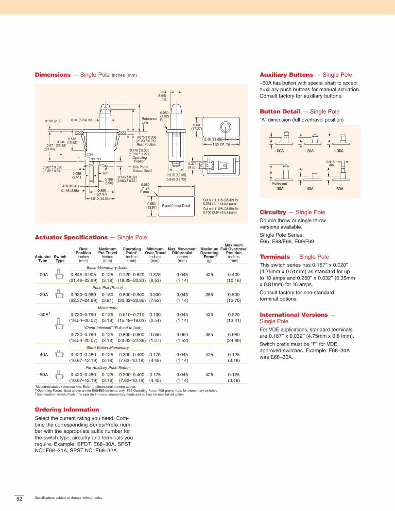
52 Specifications subject to change without notice.
0.315dia.
A
A A A
A A
Pulled out
- 00A - 20A - 30A
- 30A - 40A - 50A
Auxiliary Buttons — Single Pole–50A has button with special shaft to acceptauxiliary push buttons for manual actuation.Consult factory for auxiliary buttons.
Circuitry — Single PoleDouble throw or single throw versions available.Single Pole Series: E65, E68/F68, E69/F69
Terminals — Single PoleThis switch series has 0.187″ x 0.020″(4.75mm x 0.51mm) as standard for up to 10 amps and 0.250″ x 0.032″ (6.35mm x 0.81mm) for 16 amps. Consult factory for non-standard terminal options.
International Versions — Single PoleFor VDE applications, standard terminalsare 0.187″ x 0.032″ (4.75mm x 0.81mm).Switch prefix must be “F” for VDE approved switches. Example: F68–30Awas E68–30A.
Ordering InformationSelect the current rating you need. Com-bine the corresponding Series/Prefix num-ber with the appropriate suffix number forthe switch type, circuitry and terminals yourequire. Example: SPDT: E68–30A, SPSTNO: E68–31A, SPST NC: E68–32A.
0.97(24.64)
0.34 (8.64) dia.
1.010 (25.65)
0.080 (2.03)
0.375(9.53)
ReferenceLine
Panel Cutout Detail0.550(13.97)
Cut out 1.115 (28.32) for 0.045 (1.14) thick panelCut out 1.125 (28.58) for 0.100 (2.54) thick panel
0.050 (1.27)
R max.
1.25 (31.75)0.46 (11.68)
0.68(17.27)
0.510 (12.95)0.540 (13.72)
0.34 (8.64)
dia.
0.060(1.52)R
COMNONC
0.865(21.97)
0.145 (3.68)
0.615(15.62)0.940
(23.88)
0.099(2.51)
80°
0.156(3.96)
0.410 (10.41)
See PanelCutout Detail
0.875(22.23
0.0300.76)
+-+-Rest Position
0.770(19.56
0.0501.27)
+-+-OperatingPosition
0.145(3.683
0.0200.51)
+-+-
0.367(9.32
0.0200.51)
+-+-
Dimensions — Single Pole inches (mm)
Button Detail — Single Pole”A” dimension (full overtravel position)
Actuator Specifications — Single PoleMaximum
Rest Maximum Operating Minimum Max. Movement Maximum Full OvertravelPosition Pre-Travel Point* Over-Travel Differential Operating Position
Actuator Switch inches inches inches inches inches Force** inchesType Type (mm) (mm) (mm) (mm) (mm) (g) (mm)
Basic Momentary Action
–00A 0.845–0.905 0.125 0.720–0.820 0.375 0.045 425 0.400(21.46–22.99) (3.18) (18.29–20.83) (9.53) (1.14) (10.16)
Push-Pull (Reset)
–20A 0.920–0.980 0.150 0.800–0.900 0.300 0.045 285 0.500(22.37–24.89) (3.81) (20.32–22.86) (7.62) (1.14) (12.70)
Momentary
–30A† 0.730–0.790 0.125 0.610–0.710 0.100 0.045 425 0.520(18.54–20.07) (3.18) (15.49–18.03) (2.54) (1.14) (13.21)
“Cheat Interlock” (Pull out to lock)
0.730–0.790 0.125 0.800–0.900 0.050 0.060 385 0.980(18.54–20.07) (3.18) (20.32–22.86) (1.27) (1.52) (24.89)
Short Button Momentary
–40A 0.420–0.480 0.125 0.300–0.400 0.175 0.045 425 0.125(10.67–12.19) (3.18) (7.62–10.16) (4.45) (1.14) (3.18)
For Auxiliary Push Button
–50A 0.420–0.480 0.125 0.300–0.400 0.175 0.045 425 0.125(10.67–12.19) (3.18) (7.62–10.16) (4.45) (1.14) (3.18)
*Measured above reference line. Refer to dimensional drawing above.**Operating Forces listed above are for E68/E69 switches only. E65 Operating Force: 708 grams max. for momentary switches.†Dual function switch: Push in to operate in normal momentary mode and pull out for maintained action.

53Specifications subject to change without notice.
0.315dia.
A
A A A
A A
Pulled out
- 00A - 20A - 30A
- 30A - 40A - 50A
Auxiliary Buttons — Double Pole–50A has button with special shaft to acceptauxiliary push buttons for manual actuation.Consult factory for auxiliary buttons.
Button Detail — Double Pole”A” dimension (full overtravel position)
Ordering InformationSelect the current rating you need. Com-bine the corresponding Series/Prefix num-ber with the appropriate suffix number forthe switch type, circuitry and terminals yourequire. Example: DPDT: E78–30A, DPSTNO: E78–31A, DPST NC: E78–32A.
0.045 (1.14)0.100 (2.54)
0.97(24.64)
OperatingPosition
RestPosition0.080 (2.03)
0.375(9.53)
Reference Line
Thick Mounting Panel(see panel cutout detail)
0.550(13.97)
Cut out 1.445” (36.70) for 0.045 (1.14) thick panelCut out 1.455 (36.96) for 0.100 (2.54) thick panel
1.57 (39.88)0.79 (20.07)
0.68(17.27)
0.510 (12.95)0.540 (13.72)
0.34 (8.64)
dia.
0.060(1.52)R
COMNONC
1.24(31.5)
Panel Cutout Detail
NCNO
COM
0.050 (1.27)R max.
Dimensions — Double Pole inches (mm)
Circuitry — Double PoleDouble throw or single throw versions available.Double Pole Series: E77/F77, E78/F78, E79/F79, E75
Terminals — Double PoleThis switch series has 0.187″ x 0.020″(4.75mm x 0.51mm) as standard for up to 10 amps and 0.250″ x 0.032″ (6.35mm x 0.81mm) for 16 amps. Consult factory for non-standard terminal options.
International Versions — Double PoleFor VDE applications, standard terminalsare 0.187″ x 0.032″ (4.75mm x 0.81mm).Switch prefix must be “F” for VDE approved switches. Example: F78–30Awas E68–30A.
Actuator Specifications — Double PoleMax. Full
Rest Maximum Operating Minimum Max. Movement Maximum Over-TravelPosition Pre-Travel Point* Overtravel Differential Operating Position
Actuator Switch inches inches inches inches inches Force** inchesType Type (mm) (mm) (mm) (mm) (mm) (g) (mm)
Basic Momentary Action
–00A 0.845–0.905 0.125 0.720–0.820 0.375 0.075 680 0.400(21.46–22.99) (3.18) (18.29–20.83) (9.53) (1.91) (10.16)
Push-Pull (Reset)
–20A 0.920–0.980 0.150 0.800–0.900 0.300 0.075 510 0.500(23.37–24.89) (3.81) (20.32–22.86) (7.62) (1.91) (12.70)
Momentary
–30A† 0.730–0.790 0.125 0.610–0.710 0.100 0.075 757 0.520(18.54–20.07) (3.18) (15.49–18.03) (2.54) (1.91) (13.21)
“Cheat Interlock” (Pull out to lock)
0.730–0.790 0.155 0.800–0.900 0.030 0.090 567 0.980(18.54–20.07) (3.94) (20.32–22.86) (0.76) (2.29) (24.89)
Short Button Momentary
–40A 0.420–0.480 0.125 0.300–0.400 0.175 0.075 680 0.125(10.67–12.19) (3.18) (7.62–10.16) (4.45) (1.91) (3.18)
For Auxiliary Push Button
–50A 0.420–0.480 0.125 0.300–0.400 0.175 0.075 680 0.125(10.67–12.19) (3.18) (7.62–10.16) (4.45) (1.91) (3.18)
*Measured above reference line. Refer to dimensional drawing above.**Operating Forces listed above are for E78/E79 switches only. E75 Operating Force: 921 grams max. for momentary switches.†Dual function switch: Push in to operate in normal momentary mode and pull out for maintained action.
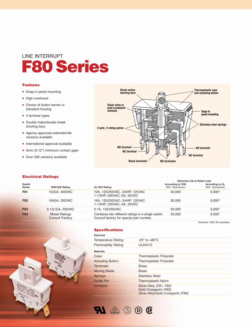
LINE INTERRUPT
F80Series
2-pole, 2-rating optionStainless steel springs
Thermoplastic caseand actuating button
Direct actionshorting bars
Snap-inpanel mounting
Silver alloy or gold crosspoint contacts
NC terminal
Brass terminals
NO terminal
NO terminals
NO terminalNC terminal
Features
Snap-in panel mounting
High overtravel
Choice of button barrier or standard housing
3 terminal types
Double make/double breakshorting bars
Agency approved extended-lifeversions available
International approval available
3mm (0.12″) minimum contact gaps
Over 200 versions available
SpecificationsElectrical
Temperature Rating: -25° to +85°CFlammability Rating: UL94V-O
Materials
Case: Thermoplastic PolyesterActuating Button: Thermoplastic PolyesterTerminals: BrassMoving Blade: BrassSprings: Stainless SteelGuide Pin: Thermoplastic NylonContacts: Silver Alloy (F81, F82)
Gold Crosspoint (F83)Silver Alloy/Gold Crosspoint (F84)
Electrical RatingsElectrical Life at Rated Load
Switch According to VDE According to ULSeries EN61058 Rating UL1054 Rating (Min. Operations) (Min. Operations)
F81 10(3)A, 400VAC 10A, 125/250VAC, 3/4HP, 125VAC 50,000 6,000*1-1/2HP, 250VAC; 6A, 30VDC
F82 16(6)A, 250VAC 16A, 125/250VAC, 3/4HP, 125VAC 50,000 6,000*1-1/2HP, 250VAC; 6A, 30VDC
F83 0.1(0.5)A, 250VAC 0.1A, 125/250VAC 50,000 6,000*F84 Mixed Ratings Combines two different ratings in a single switch. 50,000 6,000*
Consult Factory Consult factory for special part number.*Indicates 100K life available.

55Specifications subject to change without notice.
Case Styles
0.070 (1.78)Dia. (6 plcs)
0.155(3.94)
0.22(5.59)Dia.
1.05 (26.67)0.91
(23.110.020.51)
+-+-
0.36(9.14
0.020.51)
+-
+-
+-
1.213(30.81)
0.933(23.7)
1.075(27.31)
0.083(2.11)
1.24 (31.5)0.220(5.59
0.0050.18)
+-+-
0.060(1.52)R (2)
1.57 (39.88)
0.685(17.40)
0.032 x 0.250 (0.81 x 6.35)
Q.C. Terminal (6 plcs)
0.440(11.18)
Dia.
0.520(13.21)
0.499(12.68)
11° 2°(x 2)
0.060(1.52)R (4)
1.445 (36.70) for 0.045 (1.14) Thick Panel1.455 (36.96) for 0.100 (2.54) Thick Panel
0.550(13.97) Panel Cut Out
0.050 (1.27)R Max. Typ.
N.O.
N.C. N.O.
N.O.
N.C.N.O.
Reference Line
1.45±0.030(36.83±0.76)
0.522±0.015(13.26±0.38)
0.055 (1.40)Dia. (6 plcs)
0.155(3.94)
0.228(5.79)Dia.
1.05 (26.67)
0.90(22.86
0.020.51)
+-+-
0.35(8.9
0.020.51)
+-+-
0.43(10.92
0.0150.38)
+-+-
1.213(30.81)
0.40(10.16
0.0150.38)
+-+-
0.933(23.7)
1.075(27.31)
0.083(2.108)
1.24 (31.5)
0.220(5.59
0.0050.13)
+-+-0.060(1.52)R (2)
1.57 (39.88)0.79
(20.07)
0.685(17.40)0.060
(1.52)R (4)
0.187 (4.75) x0.032 (0.81) Q.C.Terminal (6 plcs)
0.543(13.79)
0.827(21.01)
0.709 (18.01)
N.O.
N.C. N.O.
N.O.
N.C.N.O.
Reference Line
1.25±0.030(31.75±0.76)
0.522±0.015(13.26±0.38)
Dimensions inches (mm)
“Cheat” Interlock
Part Number:
White: 0014-4945Red: 0014-5451
F8 2 J A 1 10**
Series/Prefix
Current Rating
Code UL/CSA VDE
1 10A, 125/250VAC; 3/4HP, 125VAC; 10(3)A1.5HP, 250VAC; 6A @ 30VDC 400VAC
2 16A, 125/250VAC; 3/4HP, 125VAC; 16(6)A1.5HP, 250VAC; 6A @ 30VDC 250VAC
3 0.1A, 125/250VAC 0.1(0.5)A250VAC
4* Mixed Ratings
Code Pole Contact Configuration
A 1 & 3 SPST NO DM2 Vacant
J 1 SPST NO DM2 SPDT NC DB3 SPDT NO DM
X 1 & 2 Vacant3 SPST NO DM
Y 1 & 3 Vacant2 SPST NC DB
Z 1 Vacant2 SPDT NC BD3 SPDT NO DM
V 1 SPST NO DM2 & 3 Vacant
Code Case
A BasicB Actuator Barrier
Code Terminal Type inches (mm)
10 0.187 x 0.020 (4.75 x 0.51) QC20 0.250 x 0.032 (6.35 x 0.81) QC40 0.187 x 0.032 (4.75 x 0.81) QC
Code Type
1 StandardW Special
Actuator SpecificationsMaximum Maximum Operating Minimum Full Over-Travel Max. RestOperating Pre-Travel Point Overtravel Position Position*
Switch Force inches inches inches inches inchesType (g) (mm) (mm) (mm) (mm) (mm)
F81J-A120 866 0.236 0.354±0.039 0.079 0.314 0.551(5.99) (8.99±0.99) (2.01) (7.98) (14.00)
F82J-A120 866 0.236 0.354±0.039 0.079 0.314 0.551(5.99) (8.99±0.99) (2.01) (7.98) (14.00)
F81A-A120 866 0.236 0.354±0.039 0.079 0.314 0.551(5.99) (8.99±0.99) (2.01) (7.98) (14.00)
F82A-A120 866 0.236 0.354±0.039 0.079 0.314 0.551(5.99) ( 8.99±0.99) (2.01) (7.98) (14.00)
F81X-A120 866 0.236 0.354±0.039 0.079 0.314 0.551(5.99) (8.99±0.99) (2.01) (7.98) (14.00)
F82X-A120 866 0.236 0.354±0.039 0.079 0.314 0.551(5.99) (8.99±0.99) (2.01) (7.98) (14.00)
F82Y-A120** 250 0.030 0.465±0.039 0.250 0.314 0.490(0.76) (8.99±0.99) (6.35) (7.98) (12.45)
*Measured above reference line. **Operating Force and Pretravel are measured when N.C. Pole Breaks.
*Special order — contact factory.
DB = Dead Break • DM = Dead Make
Pole Identification
**To order 100,000 cycle UL approved switch,last digit of part number must be ʻLʼ. Forexample: F81J-A12L1
2 3 3 21
Basic Case Housing (F82J-A120) Button Barrier Housing (F81J-B110)
Basic Case Housing
Button BarrierHousing
Button Barrierwith “Cheat”Interlock Tool
Ordering Information

POWER ROCKER SWITCH
CRSeries
Rugged press-fit terminals.250″ (6.3mm) wide x .031″ (0.8mm) thick
to fit standard Quick-Connect connectors
Stylized mattefinish bezel
Crisp detentactivation
Bright redsecondary button color available
Durable silver alloy contactsfor up to 20 amp switching
Self-locking tolerancecompensation
ribs for tight fit
Features
Rugged design with current switching up to 20 amps
2-color molded button available for maximum visibility
Lighted and non-lighted versions
Splash-proof option available
Available in a wide variety of colors
Fits to 3 panel cut-out widths
Mechanical life: min. 100,000 operations
SpecificationsElectrical
Dielectric Strength: 1000VAC for 1 minuteInsulation Resistance: 108 ohms min at 500VDCInitial Contact Resistance: 0.020 ohms maxTemperature Range: -20°C to +85°C
Materials
Actuator (non-lighted): Nylon 66 94V-2Actuator (lighted): PolycarbonateHousing: Nylon 66 94V-2Case: Nylon 66 94V-2Spring: Steel WireContacts: Silver AlloyMovable Arm: Silver-Plated Copper AlloyTerminals: Tin-Plated Copper Alloy
Electrical RatingsElectrical Life at Rated Load
Switch According to VDE According to ULSeries EN61058 Rating UL1054 Rating (Min. Operations) (Min. Operations)
CR 16(4)A, 250V~, T125 20A, 125VAC; 16A, 250VAC; 3/4HP, 250VAC 10,000 6,000

57
Code Terminal Type inches (mm)
F 0.250 (6.3) QCT 0.250 (6.3) Solder Tag
Code Actuator Type
2 Curve – One Color4 Curve – Two Color
Red Mold6 Curve – Two Color
Green Mold
Code Lighted
N Non-LightedL Lighted (Bulb 125VAC)E Lighted (Bulb 250VAC)F Lighted 5VDC IncandescentG Lighted 6VDC IncandescentH Lighted 12VDC Incandescent
Code Body Type inches (mm)
E 0.476 (12.10)Non-Washable
F 0.528 (13.41)Non-Washable
G 0.543 (13.79)Non-Washable
W 0.543 (13.79) Washable Conforms to IP42
Code Housing Color
E Charcoal GreyY GreyB BlackR RedW WhiteC Brown
Code Actuator Color
Y GreyB BlackG GreenR RedA AmberW WhiteS Semi-transparent
Nylon RedC BrownE Charcoal Grey
Code Actuator Marking
B BlankD
E O IF O —K OFF ONH l O lIP
Code Contact RatingE 20A, 125VAC; 16A, 250VAC (UL & CSA)
3/4HP, 250VAC (UL)16(4)A, 250VAC~, T125 (VDE)
CR E 2 2 F 2 F B B N E
Series
Ordering Information
Dimensions inches (mm)
1.252(31.80)
1.071±0.012(27.20±0.30)
0.031(0.80)
0.374(9.50)
0.906(23.00)
Ø0.067(Ø1.70) 0.250
(6.3)0.476
(12.10)
0.555(14.10)
0.650(16.50)
0.374(9.50)
0.23
7(6
.01[
RE
F])
0.72
4(1
8.40
)
1.45
8(3
7.03
)
0.08
3(2
.10)
0.37
4(9
.50)
RecommendedPanel Cut-Out Dimensions inches (mm)
SUFFIX E SUFFIX F SUFFIX G or W
Dim. Z Dim. X Dim. Y Dim. X Dim. Y Dim. X Dim. Y
0.030 to 0.049 1.120 0.476 1.120 0.528 1.120 0.543(0.75 to 1.25) (28.49) (12.10) (28.49) (13.41) (28.49) (13.80)0.049 to 0.079 1.130 0.476 1.130 0.528 1.130 0.543(1.25 to 2.00) (28.70) (12.10) (28.70) (13.41) (28.70) (13.80)0.079 to 0.118 1.150 0.476 1.150 0.528 1.150 0.543(2.00 to 3.00) (29.21) (12.10) (29.21) (13.41) (29.21) (13.80)
Z = Panel Thickness
X
Y
Code Circuitry
2 Single-PoleCode Switch Function
2 On – Off3 On – On4 On – Off – On
OFF
ON
OFF ON
Specifications subject to change without notice.
Note: Washable version not available lighted.
Examples of Common Part Numbers and Descriptions inches (mm)Actuator/
Part Number Circuitry Switch Function Terminal Type Housing Color Legend Marking
CRE22F2FBBNE On – Off 0.250 (6.3) Black/BlackQuick-Connect
CRE22F4BBBNE On – Off 0.250 (6.3) Red-Black/BlackQuick-Connect
CRE24F2HBBNE On – Off – On 0.250 (6.3) Black/BlackQuick-Connect
CRE22F2BBRLE On – Off/Lighted 0.250 (6.3) Red/BlackQuick-Connect
CRE22F4BBBNW On – Off 0.250 (6.3) Red-Black/Black Quick-Connect Splash-Proof
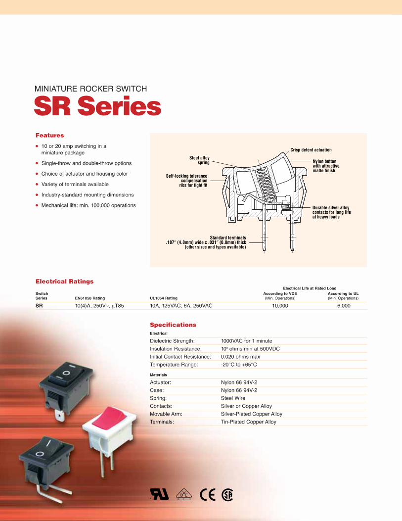
MINIATURE ROCKER SWITCH
SR Series
Steel alloyspring
Self-locking tolerancecompensation
ribs for tight fit
Crisp detent actuation
Nylon buttonwith attractivematte finish
Durable silver alloycontacts for long lifeat heavy loads
Standard terminals.187″ (4.8mm) wide x .031″ (0.8mm) thick
(other sizes and types available)
Features
10 or 20 amp switching in a miniature package
Single-throw and double-throw options
Choice of actuator and housing color
Variety of terminals available
Industry-standard mounting dimensions
Mechanical life: min. 100,000 operations
SpecificationsElectrical
Dielectric Strength: 1000VAC for 1 minuteInsulation Resistance: 108 ohms min at 500VDCInitial Contact Resistance: 0.020 ohms maxTemperature Range: -20°C to +65°C
Materials
Actuator: Nylon 66 94V-2Case: Nylon 66 94V-2Spring: Steel WireContacts: Silver or Copper AlloyMovable Arm: Silver-Plated Copper AlloyTerminals: Tin-Plated Copper Alloy
Electrical RatingsElectrical Life at Rated Load
Switch According to VDE According to ULSeries EN61058 Rating UL1054 Rating (Min. Operations) (Min. Operations)
SR 10(4)A, 250V~, μT85 10A, 125VAC; 6A, 250VAC 10,000 6,000

59
Code Terminal Type inches (mm)
A 0.187 (4.8) QCB PC Thru-Hole Left AngleC PC Thru-Hole StraightE PC Thru-Hole Right AngleP 0.346 x 0.189 (8.79 x 4.80)
Solder Tag
Code Actuator Type
2 CurveCode Lighted
N Non-Lighted
Code Splashproof
N No Rocker BootS Waterproof Boot
Code Housing Color
B BlackW WhiteY GreyC Brown
Code Actuator Color
B BlackR RedW WhiteY GreyC Brown
Code Actuator Marking
B BlankC
D
E O IF O —G •H l O ll
Code Contact Rating
B 10A, 125VAC6A, 250VAC (UL, CSA)10(4)A, 250V~, μT85 (VDE)
J 20A, 125VAC (UL, cUL)
SR B 2 4 A 2 H B B N N
Series
Ordering Information
Dimensions inches (mm)
0.81
9(2
0.80
)
0.28
0(7
.10)
0.53
9(1
3.70
)
0.13
0(3
.30
[RE
F])
0.07
9(2
.00)
0.748(19.00)
0.827(21.00)
0.732(18.60)
0.677(17.20)
0.276(7.00)
0.276(7.00)
0.031(0.80)
0.508(12.90)
0.480(12.20)
0.187(4.8)
ø0.063(ø1.60)
0.591(15.00 ±0.10)
0.378(9.60)
0.472(12.00)
0.031(0.80)
0.68
9(1
7.50
)
0.047(1.20)
0.20
9(5
.30)
2.700(0.11)
0.031(0.80) 0.472
(12.00)
Terminals
Code B Code C
Code D
Code ERecommendedPanel Cut-Out Dimensions inches (mm)Dim. Z Dim. X Dim. Y
0.030 to 0.049 0.752 0.508(0.75 to 1.25) (19.10) (12.90)0.049 to 0.079 0.760 0.508(1.25 to 2.00) (19.30) (12.90)0.079 to 0.118 0.775 0.508(2.00 to 3.00) (19.76) (12.90)
Z = Panel Thickness
X
Y
Code Circuitry
2 Single-PoleCode Switch Function
2 On – Off3 On – On4 On – Off – On5 (On) – Off
OFF
ON
LO HI
Specifications subject to change without notice.
Examples of Common Part Numbers and Descriptions inches (mm)Actuator/
Part Number Circuitry Switch Function Terminal Type Housing Color Legend Marking
SRB22A2FBBNN On – Off 0.187 (4.8) Black/BlackQuick-Connect
SRB22A2BBBNN On – Off 0.187 (4.8) Black/BlackQuick-Connect
SRB22A2DBBNN On – Off 0.187 (4.8) Black/BlackQuick-Connect
SRB23A2BBBNN On – On 0.187 (4.8) Black/BlackQuick-Connect
SRB24A2HBBNN On – Off – On 0.187 (4.8) Black/BlackQuick-Connect
Boot #0015-0644

MINIATURE ROCKER SWITCH
LR Series
Nylon button withattractive matte finish(non-lighted versions)
Self-locking tolerancecompensation
ribs for tight fit
Durable silveralloy contacts for
long life at heavy loadsRugged press-fit terminals.187″ (4.8mm) wide x .031″ (0.8mm) thick to mate with standard Quick-Connect connectorsor PC terminals
Crisp detent activation
Features
Single-pole and double-pole configurations
Lighted and non-lighted options
Available in a wide variety of colors
High current switching in a compact package
Variety of terminal styles available
Self-locking tabs to fit industry-standard panel cut-outs
Mechanical life: min. 100,000 operations
SpecificationsElectrical
Dielectric Strength: 1000VAC for 1 minuteInsulation Resistance: 108 ohms min at 500VDCInitial Contact Resistance: 0.020 ohms maxTemperature Range: -20°C to +65°C
Materials
Actuator (non-lighted): Nylon 66 94V-2Actuator (lighted): PolycarbonateCase: Nylon 66 94V-2Contacts: Silver AlloyMovable Arm: Copper AlloyTerminals: Tin-Plated Copper Alloy
Electrical RatingsElectrical Life at Rated Load
Switch According to VDE According to ULSeries EN61058 Rating UL1054 Rating (Min. Operations) (Min. Operations)
LR 10(4)A, 250V~, T125/55 10A, 125VAC; 8A, 250VAC; 1/4HP, 125/250VAC 10,000 6,000

61
Code Terminal Type inches (mm)
H 0.187 (4.8) QCL PC Thru-Hole Right AngleM PC Thru-Hole StraightG Flat Bezel; 0.240 (6.10) QC
Terminal Spacing
Code Actuator Type
2 CurveCode Lighted
N Non-LightedL Lighted
(Bulb 125VAC)E Lighted
(Bulb 250VAC)F Lighted 5VDC
IncandescentG Lighted 6VDC
IncandescentH Lighted 12VDC
Incandescent
Code Splashproof
N No Rocker BootS Rocker Boot
Code Housing ColorE Charcoal GreyB BlackW WhiteY GreyC Brown
Code Actuator ColorE Charcoal GreyB BlackG GreenA AmberR RedW WhiteY GreyS Semi-transparent
Nylon RedC Brown
Code Actuator Marking
B BlankD
E O IF O –G •
Code Contact Rating
A 10A,125VAC; 8A,250VAC;1/4HP, 125/250VAC (UL)12A,125VAC; 10A,250VAC;1/4HP, 125/250VAC (CSA)10(4)A 250 V~, T125/55 (VDE)
LR A 2 2 H 2 F B B N N
Series
Ordering Information
Dimensions inches (mm)
0.685(17.40)
0.827(21.00)
0.591(15.00)
0.98
8(2
5.10
)0.
118
(3.0
0)
0.187(4.8)
0.205(5.21)
0.157(3.99)
0.315(8.00)
0.090(2.29)
0.197(5.00)
1.031(0.80)
0.496(12.60)
0.25
6(6
.50)
0.72
8(1
8.50
)0.40
5(1
0.29
)0.
090
(2.2
9)
Z
Terminals
Code L
Code M Code G
0.598(15.20)
0.496(12.60)
0.354(9.00)
0.236(6.00)
0.059(1.50)
0.032(0.80)
0.050(1.27)
0.38
6(9
.80)
0.03
0(0
.76)
0.185 (4.70)
RecommendedPanel Cut-Out Dimensions inches (mm)Dim. Z Dim. X Dim. Y
0.030 to 0.049 0.752 0.508(0.75 to 1.25) (19.10) (12.90)0.049 to 0.079 0.760 0.508(1.25 to 2.00) (19.30) (12.90)0.079 to 0.118 0.775 0.508(2.00 to 3.00) (19.69) (12.90)
Z = Panel Thickness
X
Y
Code Circuitry
2 Single-Pole3 Double-Pole
Code Switch Function
2 On – Off
12
3
2 1
34
OFF
ON
Specifications subject to change without notice.
Examples of Common Part Numbers and Descriptions inches (mm)Actuator/
Part Number Circuitry Switch Function Terminal Type Housing Color Legend Marking
LRA22H2FBBNN On – Off 0.187 (4.8) Black/BlackQuick-Connect
LRA32H2FBBNN On – Off 0.187 (4.8) Black/BlackQuick-Connect
LRA22H2BBBNN On – Off 0.187 (4.8) Black/BlackQuick-Connect
LRA32H2BBBNN On – Off 0.187 (4.8) Black/BlackQuick-Connect
LRA22H2BBRLN On – Off/Lighted 0.187 (4.8) Red/BlackQuick-Connect
LRA32H2BBRLN On – Off/Lighted 0.187 (4.8) Red/BlackQuick-Connect
Boot #0015-0644

THIN POWER ROCKER SWITCH
TR SeriesSelf-locking tolerance
compensation ribs for tight fitCrisp detent actuation
Nylon button with attractivematte finish (non-lighted versions)
Steel alloy spring
Durable silver alloy contactsfor up to 16 amp switching
Open contact gap >3mm
Standard terminals.250″ (6.3mm) wide x .031″ (0.8mm) thick
Features
16A switching in 11mm wide package
Lighted and non-lighted versions
Available in a wide variety of colors
Double-throw and three-position versions available
Fits industry-standard cut-outs
Mechanical life: min. 50,000 operations
SpecificationsElectrical
Dielectric Strength: 1000VAC for 1 minuteInsulation Resistance: 108 ohms min at 500VDCInitial Contact Resistance: 0.020 ohms maxTemperature Range: -20°C to +65°C
Materials
Actuator (non-lighted): Nylon 66 94V-2Actuator (lighted): PolycarbonateCase: Nylon 66 94V-2Spring: Steel WireContacts: Silver AlloyMovable Arm: Silver-Plated Copper AlloyFixed Contact Terminals: Tin-Plated Copper Alloy
Electrical RatingsElectrical Life at Rated Load
Switch According to VDE According to ULSeries EN61058 Rating UL1054 Rating (Min. Operations) (Min. Operations)
TR 16(4)A, 250V~, T85 1E4 16A, 125/250VAC, 1/4HP@125V; 3/4HP@250V 10,000 6,000
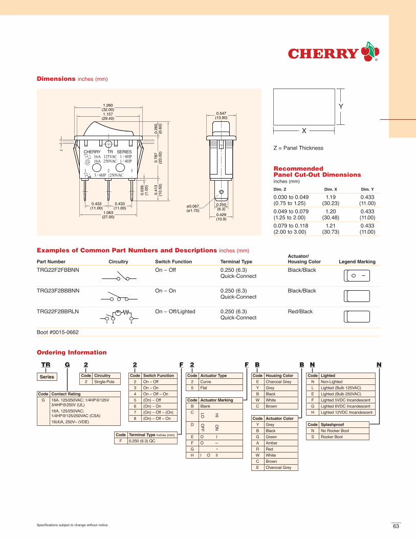
63
Dimensions inches (mm)
1.260(32.00)1.157
(29.40)
1.063(27.00)
0.433(11.00)
0.433(11.00) ø0.067
(ø1.70)
0.250(6.3)
0.429(10.9)
0.547(13.90)
0.26
0(6
.60)
0.78
7(2
0.00
)0.
413
(10.
50)
0.03
9(1
.00)
RecommendedPanel Cut-Out Dimensions inches (mm)Dim. Z Dim. X Dim. Y
0.030 to 0.049 1.19 0.433(0.75 to 1.25) (30.23) (11.00)0.049 to 0.079 1.20 0.433(1.25 to 2.00) (30.48) (11.00)0.079 to 0.118 1.21 0.433(2.00 to 3.00) (30.73) (11.00)
Z = Panel Thickness
X
Y
Code Terminal Type inches (mm)
F 0.250 (6.3) QC
Code Actuator Type
2 Curve5 Flat
Code Lighted
N Non-LightedL Lighted (Bulb 125VAC)E Lighted (Bulb 250VAC)F Lighted 5VDC IncandescentG Lighted 6VDC IncandescentH Lighted 12VDC Incandescent
Code Splashproof
N No Rocker BootS Rocker Boot
Code Housing Color
E Charcoal GreyY GreyB BlackW WhiteC Brown
Code Actuator Color
Y GreyB BlackG GreenA AmberR RedW WhiteC BrownE Charcoal Grey
Code Actuator Marking
B BlankC
D
E O IF O —G •H l O ll
Code Contact Rating
G 16A, 125/250VAC; 1/4HP@125V 3/4HP@250V (UL)16A, 125/250VAC;1/4HP@125/250VAC (CSA)16(4)A, 250V~ (VDE)
TR G 2 2 F 2 F B B N N
Series
Ordering Information
Code Circuitry
2 Single-PoleCode Switch Function
2 On – Off3 On – On4 On – Off – On5 (On) – Off6 (On) – On7 (On) – Off – (On)8 (On) – Off – On
OFF
ON
LO HI
Specifications subject to change without notice.
Examples of Common Part Numbers and Descriptions inches (mm)Actuator/
Part Number Circuitry Switch Function Terminal Type Housing Color Legend Marking
TRG22F2FBBNN On – Off 0.250 (6.3) Black/BlackQuick-Connect
TRG23F2BBBNN On – On 0.250 (6.3) Black/BlackQuick-Connect
TRG22F2BBRLN On – Off/Lighted 0.250 (6.3) Red/BlackQuick-Connect
Boot #0015-0662

DOUBLE-POLE POWER ROCKER SWITCH
WR Series
Self-locking tolerancecompensation ribs
for tight fit
Nylon button with attractivematte finish (non-lighted versions)
Steel alloy spring
Crisp detent actuation
Durable silver alloy contactsfor up to 16 amp switching
Standard terminals.250″ (6.3mm) wide x.031″ (0.8mm) thickOpen contact
gap > 3mm
Features
Rugged construction for 2-pole, high-current applications
Lighted and non-lighted
Maintained-action and momentary
Single-throw and double-throw
Available in a variety of colors
Mechanical life: min. 50,000 operations
SpecificationsElectrical
Dielectric Strength: 1000VAC for 1 minuteInsulation Resistance: 108 ohms min at 500VDCInitial Contact Resistance: 0.020 ohms maxTemperature Rating: -20°C to +65°C
Materials
Actuator (non-lighted): Nylon 66 94V-2Actuator (lighted): PolycarbonateCase: Nylon 66 94V-2Spring: Steel WireContacts: Silver AlloyMovable Arm: Silver-Plated Copper AlloyTerminals: Tin-Plated Copper Alloy
Electrical RatingsElectrical Life at Rated Load
Switch According to VDE According to ULSeries EN61058 Rating UL1054 Rating (Min. Operations) (Min. Operations)
WR 16(4)A, 250V~, T125 1E4 16A, 125/250VAC; 1/4HP@125V: 3/4HP@250V 10,000 6,000

65
Code Terminal Type inches (mm)
A 0.187 (4.8) QCF 0.250 (6.3) QCS 0.250 (6.3) M3 Tapped ScrewT 0.250 (6.3) Solder Tag
Code Actuator Type
2 Curve5 Flat Actuator7 Curve – Dual Actuator
Code Lighted
N Non-LightedL Lighted (Bulb 125VAC)E Lighted (Bulb 250VAC)F Lighted 5VDC IncandescentG Lighted 6VDC IncandescentH Lighted 12VDC Incandescent
Code Splashproof
N No Rocker BootS Rocker Boot
Code Housing Color
E Charcoal GreyY GreyB BlackW WhiteC Brown
Code Actuator Color
Y GreyB BlackG GreenA AmberR RedW WhiteC BrownE Charcoal Grey
Code Actuator Marking
B BlankC
D
E O IF O —G •H l O ll
Code Contact Rating
G 16A, 125/250VAC: 1/4HP@125V:3/4HP@250V (UL)16A, 125/250VAC: 1/4HP@125/250VAC (CSA)16(4)A, 250V~, T125 1E4 (VDE)
WR G 3 2 F 2 F B B N N
Series
Ordering Information
Dimensions inches (mm)
Flared tabson
two- positionversions
1.260(32.00)
0.031(0.80)
0.437(11.10)
0.250(6.3)
0.425(10.80)
0.437(11.10)
1.063(27.00)
1.142(29.00)
0.11
2(0
.50)
0.08
1(2
.00)
0.75
2(1
9.00
)
0.38
0(9
.30
0.39
6(1
0.00
)
ø0.067
(ø1.7
0)
0.984(25.00)
0.846(21.50)0.748
(19.00)
0.14
4(3
.65
[RE
F])
RecommendedPanel Cut-Out Dimensions inches (mm)Dim. Z Dim. X Dim. Y
0.030 to 0.049 1.180 0.867(0.75 to 1.25) (30.00) (22.02)0.049 to 0.079 1.190 0.867(1.25 to 2.00) (30.25) (22.02)0.079 to 0.118 1.200 0.867(2.00 to 3.00) (30.48) (22.02)
Z = Panel Thickness
X
Y
Code Circuitry
2 Single-Pole3 Double-Pole
Code Switch Function
2 On – Off3 On – On4 On – Off – On5 (On) – Off6 (On) – On7 (On) – Off – (On)8 (On) – Off – On
OFF
ON
LO HI
Specifications subject to change without notice.
Examples of Common Part Numbers and Descriptions inches (mm)Actuator/
Part Number Circuitry Switch Function Terminal Type Housing Color Legend Marking
WRG32F2FBBNN On – Off 0.250 (6.3) Black/BlackQuick-Connect
WRG34F2HBBNN On – Off – On 0.250 (6.3) Black/BlackQuick-Connect
WRG32F2BBRLN On – Off/Lighted 0.250 (6.3) Red/BlackQuick-Connect
Boot #0015-0646

Steel alloy spring
Rugged press-fit terminals.250″ (6.3mm) wide x .031″ (0.8mm) thickto fit standard quick-connect connectors
Nylon button withattractive matte finish
Crisp detentactivation
Self-locking tolerancecompensation ribsfor tight fit
Silver-plated copper alloycontact plate for long life
at heavy loads
Features
Economical 15 amp switching
Lighted and non-lighted versions
Available in a wide variety of colors
Single- and double-throw options
Optional wire leads available
Mechanical life: min. 50,000 operations
SpecificationsElectrical
Dielectric Strength: 1000VAC for 1 minuteInsulation Resistance: 108 ohms min at 500VDCInitial Contact Resistance: .020 ohms maxTemperature Range: -20°C to +85°C
Materials
Actuator (non-lighted): Nylon 66 94V-2Actuator (lighted): PolycarbonateHousing: Nylon 66 94V-2Base: Nylon 66 94V-2Spring: Steel WireContact Plate: Copper AlloyTerminals: Tin-Plated Copper Alloy
COMPACT ROCKER SWITCH
GR Series
Electrical RatingsElectrical Life at Rated Load
Switch According to VDE According to ULSeries EN61058 Rating UL1054 Rating (Min. Operations) (Min. Operations)
GR N/A 15A, 125VAC; 10A, 250VAC N/A 6,000

67Specifications subject to change without notice.
Code Terminal Type inches (mm)
N 0.250 (6.3) QC, StraightW Wire Lead 16 AWG, UL 1015, 6″ Long, White
Code Actuator Type
2 CurveCode Lighted
N Non-LightedL Lighted (Bulb 125VAC)E Lighted (Bulb 250VAC)G Lighted 6VDC IncandescentH Lighted 12VDC Incandescent
Code Body Type
N No Splashproof Rocker Boot
Code Housing Color
B BlackW WhiteY GreyC Brown
Code Actuator Color
B BlackG GreenA AmberR RedY GreyC BrownM YellowW White
Code Actuator Marking
B BlankC
D
E O IF O —K OFF ON
Code Contact RatingF 15A, 125VAC (UL, CSA)
10A, 250VAC (UL, CSA)
GR F 2 2 N 2 F B B N N
Series
Ordering Information
Code Circuitry
2 Single-PoleCode Switch Function
2 On – Off3 On – On
OFF
ON
LO HI
Dimensions inches (mm)
1 2 3
CHERRY GR SERIES15A 125VAC10A 250VAC
0.488(12.40)
0.250(6.3)
0.531(13.49)
0.630(16.00)
0.413(10.49)
ø0.118(ø3.00)
1.118(28.40)
1.250(31.75)
0.898(22.81)
0.250(6.3)
0.37
4(9
.50)
0.87
8(2
2.30
)0.
190
(4.8
3)
RecommendedPanel Cut-Out Dimensions inches (mm)Dim. Z Dim. X Dim. Y
0.030 to 0.049 1.120 0.535(0.76 to 1.25) (28.45) (13.59)0.049 to 0.079 1.130 0.535(1.25 to 2.01) (28.70) (13.59)0.079 to 0.118 1.150 0.535(2.01 to 3.00) (29.21) (13.59)
Z = Panel Thickness
X
Y
Examples of Common Part Numbers and Descriptions inches (mm)Actuator/
Part Number Circuitry Switch Function Terminal Type Housing Color Legend Marking
GRF22N2BBBNN On – Off 0.250 (6.3) Black/Quick-Connect Black
GRF22N2FBBNN On – Off 0.250 (6.3) Black/Quick-Connect Black
GRF23N2BBBNN On – On 0.250 (6.3) Black/Quick-Connect Black
GRF22N2BBRLN On – Off/Lighted 0.250 (6.3) Red/Quick-Connect Black

Round nylon button withattractive matte finish(non-lighted versions)
Self-locking tolerancecompensation
ribs for tight fit
Durable silveralloy contacts for
long life at heavy loadsRugged press-fit terminals.187″ (4.8mm) wide x .031″ (0.8mm) thick to mate with standard Quick-Connect connectors
Crisp detent activation
Features
Single-pole and double-pole configurations
Lighted and non-lighted options
Available in a wide variety of colors
High current switching in a compact round package
Self-locking tabs to fit industry-standard panel cut-outs
Mechanical life: min. 100,000 operations
SpecificationsElectrical
Dielectric Strength: 1000VAC for 1 minuteInsulation Resistance: 108 ohms min at 500VDCInitial Contact Resistance: .020 ohms maxTemperature Range: -20°C to +85°C
Materials
Actuator (non-lighted): Nylon 66 94V-2Actuator (lighted): PolycarbonateBase: Nylon 66 94V-2Contacts: Silver AlloyMovable Arm: Copper AlloyTerminals: Tin-Plated Copper Alloy
ROUND ROCKER SWITCH
RRSeries
Electrical RatingsElectrical Life at Rated Load
Switch According to VDE According to ULSeries EN61058 Rating UL1054 Rating (Min. Operations) (Min. Operations)
RR 10(4)A, 250V~, µ T125/55 10A, 125VAC; 8A, 250VAC, 1/4 HP; 125/250VAC 10,000 6,000

69Specifications subject to change without notice.
Ordering Information
Dimensions inches (mm)
CHERRY RR SERIES10A 125VAC 8A 250VAC12A 125VAC10A 250VAC
1/4 HP
1/4 HP
Ø.677(Ø17.20)
0.07
9(2
.00)
0.2
56(
6.50
)
0.05
9(1
.50)
0.783(19.90)
0.504(12.80)
0.315(8.00)
0.197(5.00)
0.031(0.80)
0.13
8(3
.50)
0.71
7(1
8.20
)
0.97
6(2
4.80
)
0.27
6(7
.00)
0.841(21.36)
0.157(4.00)
Ø.091(Ø2.30)
0.205(5.20)
0.030(0.76)
0.685(17.40)
0.906(23.00)
0.187(4.8)
12
3
12
34
Code Terminal Type inches (mm)
H 0.187 (4.8) QCL PC Thru-Hole Right AngleM PC Thru-Hole Straight
Code Actuator Type
3 RoundCode Lighted
N Non-LightedL Lighted
(Bulb 125VAC)E Lighted
(Bulb 250VAC)G Lighted 6VDC
IncandescentH Lighted 12VDC
Incandescent
Code Body Type
N No SplashproofRocker Boot
Code Housing ColorB BlackW WhiteY GreyC BrownE Charcoal Grey
Code Actuator ColorB BlackG GreenA AmberR RedW WhiteY GreyC BrownE Charcoal Grey
Code Actuator Marking
B BlankD
E O IF O –G •
Code Contact Rating
A 10A, 125VAC; 8A, 250VAC;1/4HP, 125/250VAC (UL)12A, 125VAC; 10A, 250VAC;1/4HP, 125/250VAC (CSA)10(4)A, 250V~, µT125/55 (VDE)
RR A 2 2 H 3 F B B N N
Series Code Circuitry
2 Single-Pole3 Double-Pole
Code Switch Function
2 On – Off
OFF
ON
0.827(21.00)
0.787
(20.00)0.09
4(2
.40)
Panel Cut-Out Dimensions for Panel Thickness inches (mm)0.039 to 0.078 (1.0 to 2.0)
Examples of Common Part Numbers and Descriptions inches (mm)Actuator/
Part Number Circuitry Switch Function Terminal Type Housing Color Legend Marking
RRA22H3BBBNN On – Off 0.187 (4.8) Black/Quick-Connect Black
RRA32H3FBBNN On – Off 0.187 (4.8) Black/Quick-Connect Black
RRA22H3BWWNN On – Off 0.187 (4.8) White/Quick-Connect White
RRA22H3FBRNN On – Off 0.187 (4.8) Red/Quick-Connect Black
RRA22H3BBRLN On – Off/Lighted 0.187 (4.8) Red/Quick-Connect Black
RRA32H3BBRLN On – Off/Lighted 0.187 (4.8) Red/Quick-Connect Black

Nylon button availablein a variety of colors
Steel alloy spring Self-locking compensationribs for tight fit
Nylon housing
Durablesilver-alloy
contacts
.146″ (3.71mm) solder tag terminals
Features
Smallest agency-approved panel-mount power rocker switch
Available in a variety of colors
Low-profile design
Mechanical life: min. 50,000 operations
PANEL-MOUNT POWER ROCKER SWITCH
PR Series
SpecificationsElectrical
Dielectric Strength: 1000VAC for 1 minuteInsulation Resistance: 108 ohms min at 500VDCInitial Contact Resistance: 20µ ohms maxTemperature Range: 0°C to +100°C (VDE), -20°C to +65°C (UL)
Materials
Actuator: Nylon 66, UL rated 94V-2Base: Nylon 66, UL rated 94V–2Spring: Piano WireContacts: Steel AlloyTerminals: Silver-Plated Copper Alloy
Electrical RatingsElectrical Life at Rated Load
Switch According to VDE According to ULSeries EN61058 Rating UL1054 Rating (Min. Operations) (Min. Operations)
PR 3A, 250VAC, T100/55 6A, 125VAC, 3A 250VAC 10,000 6,000

71Specifications subject to change without notice.
Ordering Information
Dimensions inches (mm)
ø0.059±0.005(ø1.50±0.13)
0.146(3.70)0.327(8.30)
0.157(4.00)
0.177(4.50)
0.177(4.50)
0.386(9.80)
0.39(1.00)
0.591 (15.00)
0.528 (13.40)
0.077(1.95)
0.020±0.005 (3x)(0.51±0.13)
0.248(6.30)
0.358(9.10)
0.394(10.00)0.354(9.00)
Examples of Common Part Numbers and Descriptions inches (mm)
Actuator/Switch Housing Legend
Part Number Circuitry Function Terminal Type Color Marking
PRK22J5BBBNN On – Off 0.146 (3.71) Black/Solder Tag Black
PRK22J5DBBNN On – Off 0.146 (3.71) Black/Solder Tag Black
Code Terminal Type inches (mm)
J 0.146 (3.71) Solder Tag
Code Actuator Type
5 Flat
Code LightedN Non-Lighted
Code Body Type
N No SplashproofRocker Boot
Code Housing ColorB BlackW WhiteY Grey
Code Actuator ColorB BlackR RedW WhiteY Grey
Code Actuator Marking
B Blank
C
D
E O I
F O –
G •
Code Contact Rating
K 6A 125VAC, 3A 250VAC (UL, cUL)3A 250V~ T100/55 (VDE)
PR K 2 2 J 5 B B B N N
Series Code Circuitry
2 Single-Pole
Code Switch Function
2 On – Off
OF
F
ON
LO HI
RecommendedPanel Cut-Out Dimensions inches (mm)
Dim. Z Dim. X Dim. Y
0.030 to 0.049 0.535 0.362 ±.004(0.75 to1.25) (13.6) (9.2 ±0.10)
0.049 to 0.079 0.539 0.362 ±.004(1.25 to 2.00) (13.7) (9.2 ±0.10)
0.079 to 0.098 0.543 0.362 ±.004(2.00 to 2.50) (13.8) (9.2 ±0.10)
Z = Panel Thickness
Y
X
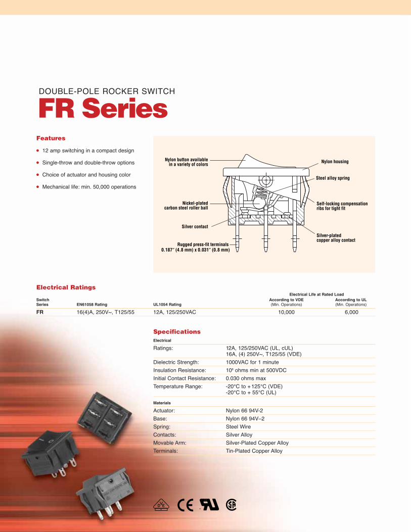
Nylon button availablein a variety of colors
Steel alloy spring
Self-locking compensationribs for tight fit
Silver-plated copper alloy contact
Nylon housing
Nickel-platedcarbon steel roller ball
Silver contact
Rugged press-fit terminals 0.187″ (4.8 mm) x 0.031″ (0.8 mm)
Features
12 amp switching in a compact design
Single-throw and double-throw options
Choice of actuator and housing color
Mechanical life: min. 50,000 operations
DOUBLE-POLE ROCKER SWITCH
FR Series
SpecificationsElectrical
Ratings: 12A, 125/250VAC (UL, cUL)16A, (4) 250V~, T125/55 (VDE)
Dielectric Strength: 1000VAC for 1 minuteInsulation Resistance: 108 ohms min at 500VDCInitial Contact Resistance: 0.030 ohms maxTemperature Range: -20°C to +125°C (VDE)
-20°C to + 55°C (UL)
Materials
Actuator: Nylon 66 94V-2Base: Nylon 66 94V–2Spring: Steel WireContacts: Silver AlloyMovable Arm: Silver-Plated Copper AlloyTerminals: Tin-Plated Copper Alloy
Electrical RatingsElectrical Life at Rated Load
Switch According to VDE According to ULSeries EN61058 Rating UL1054 Rating (Min. Operations) (Min. Operations)
FR 16(4)A, 250V~, T125/55 12A, 125/250VAC 10,000 6,000

Specifications subject to change without notice.
Ordering Information
Dimensions inches (mm)
CHERRY FR SERIES12A 125 / 250VAC
IB I IA
0.827(21.00)
0.728(18.50)
0.276(7.00)
0.031(0.80)
0.260(6.60)
0.866(22.00)
0.402(10.20)
0.187(4.80)
ø0.059(ø1.50)
0.472(12.00)
0.079(2.00)
0.780(19.80)
0.138±0.02(3.51±0.5)
Examples of Common Part Numbers and Descriptions inches (mm)
Actuator/Switch Housing Legend
Part Number Circuitry Function Terminal Type Color Marking
FRH32A2DBBNN On – Off 0.187 (4.80) Black/Quick-Connect Black
FRH33A2BBBNN On – On 0.187 (4.80) Black/Quick-Connect Black
FRH32A2BBBNN On – Off 0.187 (4.80) Black/Quick-Connect Black
FRH32A2FWWNN On – Off 0.187 (4.80) White/Quick-Connect White
FRH32A2BBWNN On – Off 0.187 (4.80) White/Quick-Connect Black
FRH32A2FBBNN On – Off 0.187 (4.80) Black/Quick-Connect Black
Code Terminal Type inches (mm)
A 0.187 (4.80) Quick-Connect
U 0.118 (3.0) Solder Tag
Code Actuator Type
2 Curve – One Color
Code LightedN Non-Lighted
Code Body Type
N No SplashproofRocker Boot
Code Housing ColorB BlackW WhiteY Grey
Code Actuator ColorB BlackD OrangeG GreenR RedW WhiteY Grey
Code Actuator Marking
B Blank
C
D
E O I
F O –
G •
Code Contact Rating
H 12A 125/250VAC (UL, cUL)16(4)A 250V~ T125 (VDE)
FR H 2 2 A 2 F B B N N
Series Code Circuitry
2 Single-Pole
3 Double-Pole
Code Switch Function
2 On – Off
3 On – On
OF
F
ON
LO HI
RecommendedPanel Cut-Out Dimensions inches (mm) ±0.002 (0.005)
Dim. Z Dim. X Dim. Y
0.030 to 0.049 0.752 0.862(0.76 to1.25) (19.15) (21.90)
0.049 to 0.079 0.760 0.862(1.24 to 2.00) (19.35) (21.90)
0.079 to 0.118 0.775 0.862(2.01 to 3.00) (19.75) (21.90)
Z = Panel Thickness
Y
X
73
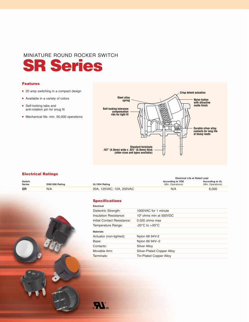
Steel alloyspring
Self-locking tolerancecompensation
ribs for tight fit
Crisp detent actuation
Nylon buttonwith attractivematte finish
Durable silver alloycontacts for long lifeat heavy loads
Standard terminals.187″ (4.8mm) wide x .031″ (0.8mm) thick
(other sizes and types available)
Features
20 amp switching in a compact design
Available in a variety of colors
Self-locking tabs and anti-rotation pin for snug fit
Mechanical life: min. 50,000 operations
MINIATURE ROUND ROCKER SWITCH
SR Series
SpecificationsElectrical
Dielectric Strength: 1000VAC for 1 minuteInsulation Resistance: 108 ohms min at 500VDCInitial Contact Resistance: 0.020 ohms maxTemperature Range: -20°C to +65°C
Materials
Actuator (non-lighted): Nylon 66 94V-2Base: Nylon 66 94V–2Contacts: Silver AlloyMovable Arm: Silver-Plated Copper AlloyTerminals: Tin-Plated Copper Alloy
Electrical RatingsElectrical Life at Rated Load
Switch According to VDE According to ULSeries EN61058 Rating UL1054 Rating (Min. Operations) (Min. Operations)
SR N/A 20A, 125VAC; 12A, 250VAC N/A 6,000

75
Ordering Information
Dimensions inches (mm)
0.31(0.80)
ø0.063ø(1.60)
0.187(4.80)
ø0.780 (ø19.8)
0.079 (2.00)
0.031 (0.80)
0.031 (0.80)
0.276(7.00)
0.030 (7.60)
0.539(13.80)
0.142 (3.6) REF
Code Terminal Type inches (mm)
A 0.187 (4.80) Quick-Connect
Code Actuator Type
3 RoundCode Lighted
N Non-Lighted
Code Body Type
N No Rocker Boot
Code Housing ColorB BlackC BrownE Charcoal GreyW WhiteY Grey
Code Actuator ColorA AmberB BlackG GreenR RedW WhiteY Grey
Code Actuator Marking
B BlankC
D
E O IF O –G •H I O I I
Code Contact Rating
J 20A, 125VAC;12A, 250VAC (UL, cUL)
SR J 2 4 A 3 H B B N N
Series Code Circuitry
2 Single-PoleCode Switch Function
2 On – Off3 On – On4 On – Off – On
OFF
ON
LO HI
Panel Cut-Out Dimensionsfor Panel Thickness inches (mm)0.039 to 0.078 (1.0 to 2.0)
Examples of Common Part Numbers and Descriptions inches (mm)Actuator/
Switch Housing LegendPart Number Circuitry Function Terminal Type Color Marking
SRJ22A3BBBNN On – Off 0.187 (4.80) Black/Quick-Connect Black
SRJ23A3BBBNN On – On 0.187 (4.80) Black/Quick-Connect Black
SRJ24A3BBBNN On – Off – On 0.187 (4.80) Black/Quick-Connect Black
SRJ22A3WWNN On – Off 0.187 (4.80) White/Quick-Connect White
SRJ22A3FBBNN On – Off 0.187 (4.80) Black/Quick-Connect Black
0.827±0.004(21.00±0.10)
0.787+0.004
-0.000
20.00+0.10
-0.00
0.094±0.0042.40±0.10
Specifications subject to change without notice.
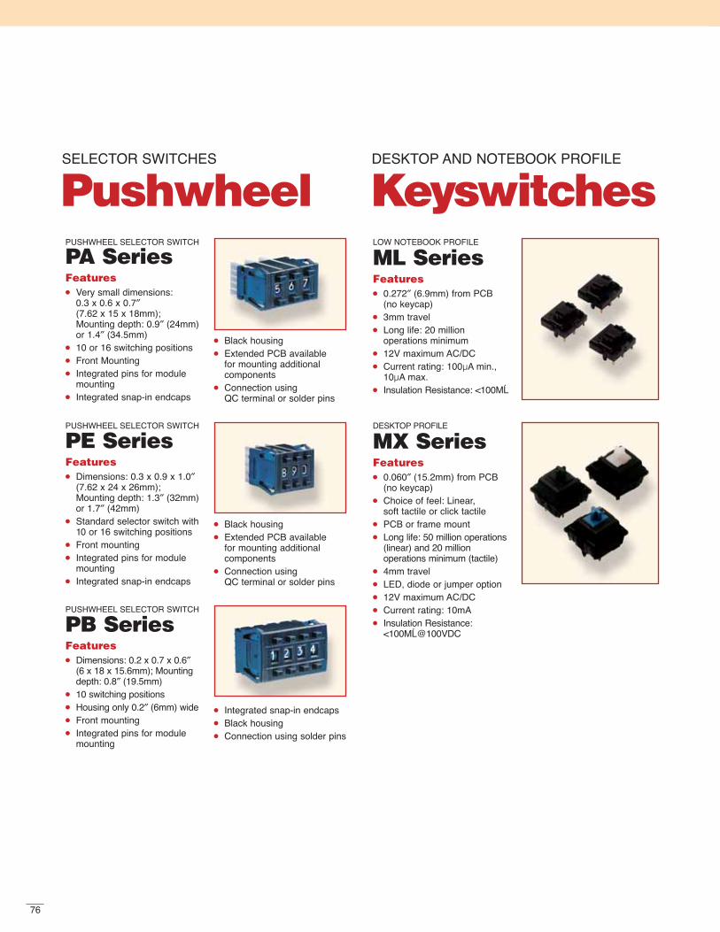
76
PUSHWHEEL SELECTOR SWITCH
PA SeriesFeatures Very small dimensions:
0.3 x 0.6 x 0.7″(7.62 x 15 x 18mm); Mounting depth: 0.9″ (24mm)or 1.4″ (34.5mm)
10 or 16 switching positions Front Mounting Integrated pins for module
mounting Integrated snap-in endcaps
Black housing Extended PCB available
for mounting additional components
Connection using QC terminal or solder pins
DESKTOP PROFILE
MX SeriesFeatures 0.060″ (15.2mm) from PCB
(no keycap) Choice of feel: Linear,
soft tactile or click tactile PCB or frame mount Long life: 50 million operations
(linear) and 20 million operations minimum (tactile)
4mm travel LED, diode or jumper option 12V maximum AC/DC Current rating: 10mA Insulation Resistance:
<100MĹ@100VDC
LOW NOTEBOOK PROFILE
ML SeriesFeatures 0.272″ (6.9mm) from PCB
(no keycap) 3mm travel Long life: 20 million
operations minimum 12V maximum AC/DC Current rating: 100µA min.,
10µA max. Insulation Resistance: <100MĹ
PUSHWHEEL SELECTOR SWITCH
PB SeriesFeatures Dimensions: 0.2 x 0.7 x 0.6″
(6 x 18 x 15.6mm); Mountingdepth: 0.8″ (19.5mm)
10 switching positions Housing only 0.2″ (6mm) wide Front mounting Integrated pins for module
mounting
Integrated snap-in endcaps Black housing Connection using solder pins
PUSHWHEEL SELECTOR SWITCH
PE SeriesFeatures Dimensions: 0.3 x 0.9 x 1.0″
(7.62 x 24 x 26mm); Mounting depth: 1.3″ (32mm)or 1.7″ (42mm)
Standard selector switch with10 or 16 switching positions
Front mounting Integrated pins for module
mounting Integrated snap-in endcaps
Black housing Extended PCB available
for mounting additional components
Connection using QC terminal or solder pins
SELECTOR SWITCHES
PushwheelDESKTOP AND NOTEBOOK PROFILE
Keyswitches

77
LIGHTED PUSHBUTTON
L4 SeriesFeatures Standard or recessed buttons Lighted or non-lighted Icons and legends Variety of lens cap colors Chrome or brass plating on
bezel at nominal charge Other styles available. Con-
tact factory.
SUB-SUBMINIATURE
CS SeriesFeatures 5mm stroke and 4mm over-
travel give designers largemechanical margin
Sliding contact technologyensures high reliability
Snap-in panel mounting or PC board mounting
Easy connection by a connector (snap-in panel mounting type)
LINE INTERRUPT
DD SeriesFeatures Small size Low operation force Meets UL 1950 Dielectric strength: 2000VAC Various terminal and
actuator types Double return springs 3mm minimum contact gap Double make contact bar
TERMINATOR
DN SeriesFeatures Plug-in termination saves
time and money Mates with standard
0.025″ (0.64mm) square pinconnectors on 0.100″ (2.54mm)centers (Example: Molex 50-57-9402)
Three methods of mounting:Traditional screw mount, Ver-tical snap-in mount and Hori-zontal snap-in mount
Long life coil spring mechanism Two current ratings SPST NO
THREE-CIRCUIT LINE INTERRUPT
F85 SeriesFeatures Meets UL 1950 8mm contact gap (4mm/side) Snap in panel mounting Agency approved extended
life versions available
ADDITIONAL
Switch Products
TWO-CIRCUIT LINE INTERRUPT
FA SeriesFeatures Compact size Low operating force Long stroke Snap in panel mounting Three-circuit model available

78
File E23301Canadian approval through ULFile 16503 — CanadaCanadian Standards Associa-tionFile E23301(per UL 1054 for special use switches) — USAUnderwriters Laboratories, Inc.File No. on Request — VDE Verband DeutscherElectrotechniker
Government ListingsCage Code: 01963Federal ID: 36-2977756Federal Business Code: 03680
TECHNICAL SECTION
GlossaryActuation ForceForce measured exactly when switchchanges state; when the actuator is moved from rest to operating position.
Auxiliary ActuatorAn external switch component that will increase travel and/or reduce the actuating force.
Actuation LengthThe external actuatorʼs dimensionfrom the round (versus elongated) mounting hole to the actuation line.
Break-Before-MakeThis term is used in connection with contacts where the moving contact, in transferring from one position to another, interrupts one circuit before establishing the next.
ContactIn devices used for making and breaking electrical currents, the component that disengages to cause the actual circuit rupture.
Contact ConfigurationA desired arrangement of contacts/circuits.See switch abbreviations, forms and poles.
Contact GapThe distance between a pair of open contacts.
Contact PressureContact pressure is the amount of forceholding the movable and stationary contactstogether. While this should be termedContact Force, by convention in the United States, it is called Contact Pressure.
Contact ResistanceThe junction resistance between two contacts, but usually measured at contact terminals. It includes the terminalresistance. Measuring volts and ampsshould be similar to intended application.
Contact WipeSliding of one contact over another duringactuation of switch.
CrosspointGold contact prisms are welded at rightangles to each other providing maximumcontact pressure and minimum hazard of contact closure interference. Used exclusively for low energy switching.
Dielectric StrengthThe property of an insulating materialwhich determines the maximum potentialgradient that the material can withstandwithout rupture.
Double BreakA form of switch contact construction inwhich a current carrying member bridges a gap at two adjacent points, one at eachend of the bridging member.
Form AA single pole, single throw, normally open contact or SPST NO.
Form BA single pole, single throw, normally closed contact or SPST NC.
Form CA single pole double throw contact or SPDT.
2-Form CA double pole, double throw contact or DPDT.
High Ratio PositionThe actuator mounting position closest to the switch button.
MakeA term used to indicate that a switch has completed the dynamics of closing an electrical circuit.
Momentary ActionThe circuit is either opened or closed, only as long as the switch is actuated.
Normally OpenA term used to describe contacts that are open in the rest position.
Normally ClosedA term used to describe contacts which establish a circuit when in the rest position.
PolesThe number of separate circuits that can beactivated through a switch at any one time.
Reference LineAlso known as datum line. Used as a basisfor calculating the operating characteristicsof a switch.
Standard Ratio PositionThe actuator mounting position furthest from the switch button.
Switch AbbreviationsSPST: Single pole single throwSPDT: Single pole double throwDPST: Double pole single throwDPDT: Double pole double throw3PDT: Three pole double throw4PDT: Four pole double throw5PDT: Five pole double throw
ThrowThe number of circuit paths that can becontrolled by one pole.
Agency Approvals
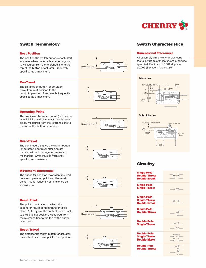
RestPosition
OperatingPosition
Pre-Travel
Over-Travel
Move DifferentialActuating Line
HorizontalDatum
VerticalDatum
Low Ratio(Std)
HighRatio
Specifications subject to change without notice.
Switch Terminology
Circuitry
Single-PoleDouble-ThrowDouble-Break
Single-PoleSingle-Throw
Single-PoleSingle-ThrowDouble-Break
Single-PoleDouble-Throw
Double-PoleSingle-Throw
Double-PoleSingle-ThrowDouble-Make
Double-PoleDouble-Throw
Reference Line
Reference Line
Reference Line
Rest PositionThe position the switch button (or actuator)assumes when no force is exerted againstit. Measured from the reference line to thetop of the button or actuator. Frequentlyspecified as a maximum.
Pre-TravelThe distance of button (or actuator) travel from rest position to the point of operation. Pre-travel is frequentlyspecified as a maximum.
Operating PointThe position of the switch button (or actuator)at which initial switch contact transfer takesplace. Measured from the reference line tothe top of the button or actuator.
Over-TravelThe continued distance the switch button (or actuator) can travel after contact transfer, without damage to the switchmechanism. Over-travel is frequently specified as a minimum.
Movement DifferentialThe button (or actuator) movement requiredbetween operating point and the resetpoint. This is frequently dimensioned as a maximum.
Dimensional TolerancesAll assembly dimensions shown carry the following tolerances unless otherwisespecified: Decimals: ±0.002 (2 place),±0.005 (3 place). Angles: ±5°.
Reset PointThe point of actuation at which the second or return contact transfer takesplace. At this point the contacts snap back to their original position. Measured from the reference line to the top of the button or actuator.
Reset TravelThe distance the switch button (or actuator)travels back from reset point to rest position.
Switch Characteristics
Miniature
Subminiature
RestPosition
OperatingPosition
Pre-Travel
Over-Travel
Move DifferentialActuating Line
HorizontalDatum
VerticalDatum

In North America
Cherry Electrical Products
11200 88th AvenuePleasant Prairie, WI 53158
Phone: (1) 800 927 6298Fax: (1) 262 942 6566
In Europe
Cherry GmbH
CherrystrasseD-91275 Auerbach/Opf.Germany
Phone: (49) (0) 9643 18 0Fax: (49) (0) 9643 18 1295
In Asia
Cherasia Ltd.
13/F, Block ANorth Point Industrial Bldg.499 King’s RoadNorth Point Hong KongChina
Phone: (852) (0) 2565 6678 Fax: (852) (0) 2565 6827
For more than 50 years, Cherry ElectricalProducts has been dedicated to providingour customers with innovative and reliablesolutions to all their switching requirements.This catalog includes thousands of varia-tions from which to select — from the snap-action models for which we are best knownto a full line of new rocker switches.
In addition to our broad product offering, ourhighly trained engineers are always availableto help you find the right solution for yourapplication — whether it is a standard modelor a custom snap-action switch.
Cherry also manufactures a full range ofmagnetic speed and proximity sensors forOEM applications, as well as a completeline of general purpose and advanced performance keyboards.
For additional information on any of our products or services, call or visit our Web site today.
www.cherrycorp.com
Selection, Quality and Support
© 2006 Cherry Corporation • Printed in U.S.A.
Cherry Corporation disclaims any warranties of merchantability,fitness for a particular purpose or noninfringement. WhileCherry Corporation intends for this information to be accurate,there may be inadvertent technical and typographical errors, for which Cherry Corporation assumes no liability.