materials and design - fudan...
TRANSCRIPT

Materials and Design 32 (2011) 671–681
Contents lists available at ScienceDirect
Materials and Design
journal homepage: www.elsevier .com/locate /matdes
Corrosion evaluation of one dry desulfurization equipment – Circulatingfluidized bed boiler
Yi Gong, Zhen-Guo Yang *
Department of Materials Science, Fudan University, Shanghai 200433, PR China
a r t i c l e i n f o a b s t r a c t
Article history:Received 12 May 2010Accepted 3 August 2010Available online 7 August 2010
Keywords:Failure analysisCorrosionFracture
0261-3069/$ - see front matter � 2010 Elsevier Ltd. Adoi:10.1016/j.matdes.2010.08.003
* Corresponding author. Tel.: +86 21 65642523; faxE-mail address: [email protected] (Z.-G. Yang)
As a clean fuel combustion technology, circulating fluidized bed (CFB) possesses various advantages.Among them, flexibility in fuels and superiority in desulfurization are the two prominent ones and canhereby facilitate sufficient utilization of high-sulfur fuels. But unfortunately, these low-grade fuelsalways introduce harsh service environment within the CFB boilers and consequently result in severedegradation extent on relevant equipments, especially the high-temperature sulfur corrosion. In thisevent, by nearly ten characterization methods, comprehensive investigation was carried out on a wholeCFB boiler during downtime, and special emphasis was particularly laid on the failure componentsincluding one perforated nozzle along with its fractured inlet tube for primary air, and one perforatedmanhole door of refeed valve. Finally, countermeasure and suggestion was put forward, which can pro-vide instructive significance in corrosion prevention for the CFB boilers, even other desulfurization equip-ments, running under similar aggressive conditions in engineering practice.
� 2010 Elsevier Ltd. All rights reserved.
1. Introduction
With the increasing demand for energy conservation and envi-ronmental protection, higher utilization of fossil fuels and loweremission of air pollution are presently the two prior concerns tofossil power plants. As for the former one, popularization of new-generation ultra-supercritical (USC) boilers is the most effectiveand attractive approach, and our previous work carried out anintegrity evaluation of the dissimilar steels welded joints that areoften encountered in these USC boilers [1]. With respect to the lat-ter one (air pollution), the sulfur pollution, which commonly refersto the sulfur dioxide, is actually the most hazardous factor result-ing in acid rain. So as to relieve the extent of this kind of pollution,there currently exist two common ways of desulfurization, one isthe fluidized bed combustion (FBC) technology and the other isthe flue gas desulfurization (FGD) process. FBC is virtually a typeof dry desulfurization and desulfurizes simultaneously with com-bustion under dry condition in furnace, while FGD is a sort ofwet desulfurization and needs specific exteriorized FGD equip-ments for desulfurizing amid wet condition. In fact, compared withthe conventional fossil power plants, the most distinct advantageof FBC and FGD is their supreme flexibility in fuels, such as coal,oil, biomass, peat, petrol coke and so on, particularly for thoselow-grade fuels with high sulfur content [2,3]. Consequently, thesetwo kinds of world-widely used desulfurization technologies are
ll rights reserved.
: +86 21 65103056..
especially popularized in China in order to satisfy her natural con-dition of high reserves of low-grade coals [4]. Statistically, in theyear 2008 over three quarters of total installed capacity of Chinawas fossil power, and among which 66% (379 million kW) wasfrom those plants installed with desulfurization equipments [5].Hence, normal and safe operation of these FBC and FGD equip-ments is of critical importance for China [6].
Only in terms of the FBC, three variants have been evolved sinceits introduction in 1970s, including bubbling fluidized bed (BFB),circulating fluidized bed (CFB) and a hybrid type between BFB andCFB [7]. Among them, CFB is presently the most universal FBC tech-nology thanks to its relatively higher combustion efficiency thanBFB. Also for China, she now owns the largest amount and thermalcapacity of CFB boilers in the world as well [8]. The unique feature ofa CFB boiler compared with the conventional boilers is the addedequipment called cyclone, which is used to refeed the incompletelycombusted fuel particles and ashes back into the furnace for re-fir-ing, i.e. the circulating function. As a result, fuels can be fully utilizedand the sulfur in them can be sufficiently eliminated before beingexhausted. In addition, configurations of CFB boilers usually varyaccording to different companies’ designs, and the two leading onesare from Foster Wheeler (FW, USA/Finland) and GEC-Alstom(France) [4]. However in fact, high desulfurization efficiency com-monly brings about harsh service environment for the CFB boilersat the same time, especially for those fire high-sulfur fuels like thepetrol coke, and will consequently result in degradations on rele-vant equipments [9–15]. But actually, large amount of the past re-searches mainly focused on the heat transfer efficiency [16–19],
672 Y. Gong, Z.-G. Yang / Materials and Design 32 (2011) 671–681
the particle hydrodynamics [20–22], and the gas/solid separationmechanisms [23,24], etc. in CFB boilers.
In this paper, various types of corrosion degradation such as uni-form corrosion, dew point corrosion, intergranular corrosion, ero-sive wear, scaling, ablation, etc. were detected in one FW CFBboiler that fired high-sulfur petrol coke and pulverized coal (3:1,wt.%) after five-year service in a petrochemical works in Shanghai.Among them, perforation on a manhole door of the refeed valve andfracture on an inlet tube for primary air were the two prior risks.Thus, by means of nearly ten characterization methods, causes ofthe two failure components were detailedly studied. Photoelectricdirect reading spectrometer and metallographic microscope (MM)were employed to inspect the chemical compositions and themetallographic structures of the matrix metals; X-ray diffraction(XRD), X-ray fluorescence (XRF), ion chromatograph (IC) and ther-mogravimetric analysis (TGA) were applied to analyze the charac-teristics of the corrosion products; scanning electron microscope(SEM) and energy disperse spectroscope (EDS) were used to detectthe micro morphologies and micro-area compositions of the frac-tured surfaces. Based on the analysis results, causes and mecha-nisms of the corrosion degradations currently existing werediscussed. Such a comprehensive corrosion evaluation on a wholeFW CFB boiler whose major fuel was high-sulfur petrol coke wasseldom reported in literatures, and it will have a critical significancein both the solution to and the prevention of corrosions for CFB boil-ers running under similar service conditions in the future.
2. Visual observation
The total fossil power unit in this event was made up of two setsof 310 t/h FW CFB boilers and a 100 MW double extraction con-densing steam turbine. Further detailed, Fig. 1 presents the sche-matic diagram of the concrete operation procedures of the CFBboilers, which were mainly composed of three systems includingthe combustion system, the gas–solid separation system and thesteam system. The corrosion evaluation was just conducted inone of the two CFB boilers, and was successively carried out accord-ing to the order of ‘left to right’ and ‘bottom to top’ basing on Fig. 1.
2.1. Combustion system
Combustion system commonly consists of a primary air cham-ber, an air distribution plate, a combustor, a furnace and a coalfeeding system. Evaluation was particularly conducted on the noz-
Fig. 1. Schematic diagram of the operati
zles lying on the air distribution plate and the water walls attachedon the furnace inner wall, since both of the two components di-rectly contacted the corrosive fuels and the flowing particles with-in the furnace and were consequently prone to failure incidents.
Air distribution plate is commonly installed on the bottom ofthe furnace and the nozzles on it are used to not only supportthe bed materials like limestone and fuels but also evenly dividethe primary air, seen in Fig. 2a. It can be also learned fromFig. 2a that no obvious corrosion evidences were detected on al-most all the nozzles. However, failure incident was actually discov-ered on some individual one. As is shown in Fig. 2b, for one specificnozzle, perforation occurred at the juncture between the nozzleand its inlet tube for primary air, and trace of ablation can alsobe observed around the perforation, which may have been causedby the high temperature effect from the localized accumulatingbed materials. Furthermore, fracture was engendered on this inlettube as well, seen in Fig. 2c. Compared with the fracture surfacefrom manual wire cutting (the upper part in Fig. 2c), the fracturesurface from failure (the lower part in Fig. 2c) was far narrower,even the width of the narrowest part (0.5 mm) was only one-tenthof its original normal value (5 mm), which meant that the fracturewas possibly induced by the erosive wear. Besides these, anothersignificant phenomenon was that the two locations of the perfora-tion and the fracture were on the same side of the nozzle. In otherwords, the generations of the thinning and fracture on the inlettube, as well as the perforation on the nozzle may have been re-lated to each other. To sum up, although failure took place in justone specific nozzle, further investigation was still needed to thor-oughly understand its causes and mechanisms for purpose of pre-vention of similar failures in other nozzles in the future.
Installed on the furnace inner wall, the platen water wall is al-ways subjected to severe service conditions including corrosion,impact, erosive wear, etc. from fuels and bed materials. Amongthem, the erosive wear is the most frequent degradation. As for thisCFB boiler, that rule was verified as well, seen in Fig. 3a. However,according to Fig. 3b, the extent of the erosive wear was not serious.Meanwhile, no other obvious failure phenomena were discoveredtoo. Hence, it can be concluded that water wall of the CFB boilerwas basically qualified after service.
2.2. Gas–solid separation system
Gas–solid separation system, which is the largest distinguishingfeature of CFB, is made up of a cyclone and a refeed valve. Limited
on procedures of the FW CFB boiler.

Fig. 2. External appearances of the nozzles (a) layout of nozzles on the furnace bottom (b) perforation on the failure nozzle and (c) fractograph of the failure inlet tube.
Fig. 3. External appearances of the platen water wall (a) total morphology and (b) phenomenon of erosive wear.
Fig. 4. External appearances of the manhole door A (a) the whole refeed valve, (b) scaling morphology and (c) magnification of scaling substance.
Y. Gong, Z.-G. Yang / Materials and Design 32 (2011) 671–681 673
to the practical conditions, investigation could only be carried outon the refeed valve. But actually, perforation of one manhole doorof the refeed valve was one of the prominent failures in this event.
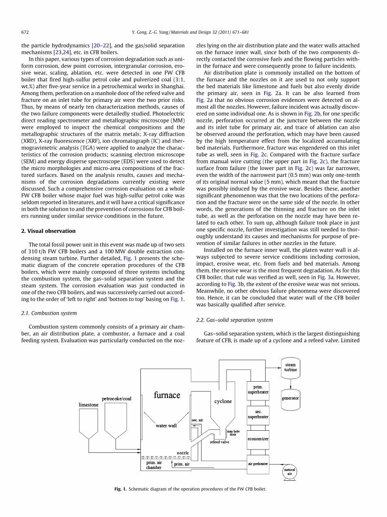
Fig. 4a displays the external appearance of the refeed valve,which owned two manhole doors respectively named A and Bon its two sides. It can be learned from Fig. 4b that scaling hadoccurred on the surface of the refractory on the manhole doorA, and the scaling substance was green and viscous liquid, seenin Fig. 4c. With respect to the failures on the manhole door B, be-sides the self-detachment of the refractory on it, two perforationscould also be found (Fig. 5a), and the diameter of the bigger onehad reached about 10 cm, seen in Fig. 5b. Moreover, it is obviousin Fig. 5c that scaling was also engendered at the edge, but thescaling substance exhibited the morphology as yellow1 and greysolid, different from that on the manhole door A. As there were sev-
1 For interpretation of color in Fig. 5, the reader is referred to the web version ofthis article.
eral entirely different types of failure phenomena on the two man-hole doors of the refeed valve, further characterization methodswould be carried out to determine the causes and mechanisms ofthem.
2.3. Steam system
Like conventional power plants, the CFB boiler also possesses acomplete steam system to fully utilize the steam heat. The only dif-ference of this FW CFB boiler was that the reheater was substitutedby the secondary superheater, seen in Fig. 1. Evaluation would becarried out on all the four steam equipments including the primarysuperheater, the secondary superheater, the economizer and theair preheater in this system.
Fig. 6 shows the external appearances of the primary super-heater, whose manhole door was covered with brown rust, seenin Fig. 6a. Likewise, rust was detected on even all the steam pipingas well (Fig. 6b). Hence, it can be concluded that the only degrada-
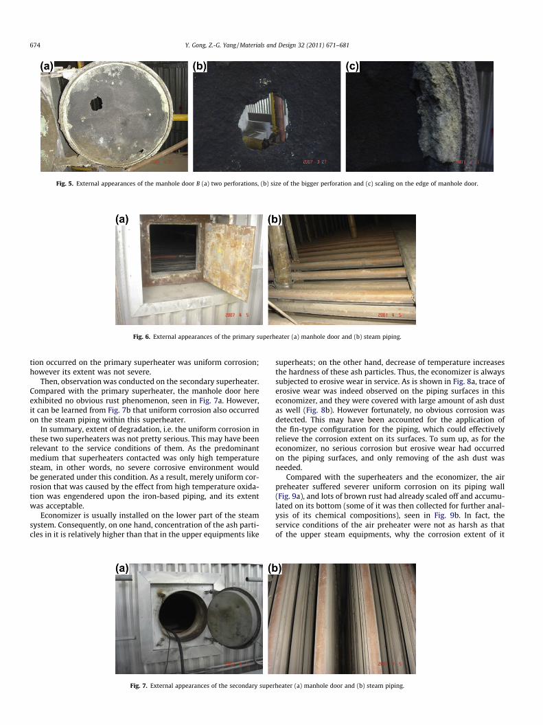
Fig. 5. External appearances of the manhole door B (a) two perforations, (b) size of the bigger perforation and (c) scaling on the edge of manhole door.
Fig. 6. External appearances of the primary superheater (a) manhole door and (b) steam piping.
674 Y. Gong, Z.-G. Yang / Materials and Design 32 (2011) 671–681
tion occurred on the primary superheater was uniform corrosion;however its extent was not severe.
Then, observation was conducted on the secondary superheater.Compared with the primary superheater, the manhole door hereexhibited no obvious rust phenomenon, seen in Fig. 7a. However,it can be learned from Fig. 7b that uniform corrosion also occurredon the steam piping within this superheater.
In summary, extent of degradation, i.e. the uniform corrosion inthese two superheaters was not pretty serious. This may have beenrelevant to the service conditions of them. As the predominantmedium that superheaters contacted was only high temperaturesteam, in other words, no severe corrosive environment wouldbe generated under this condition. As a result, merely uniform cor-rosion that was caused by the effect from high temperature oxida-tion was engendered upon the iron-based piping, and its extentwas acceptable.
Economizer is usually installed on the lower part of the steamsystem. Consequently, on one hand, concentration of the ash parti-cles in it is relatively higher than that in the upper equipments like
Fig. 7. External appearances of the secondary super
superheats; on the other hand, decrease of temperature increasesthe hardness of these ash particles. Thus, the economizer is alwayssubjected to erosive wear in service. As is shown in Fig. 8a, trace oferosive wear was indeed observed on the piping surfaces in thiseconomizer, and they were covered with large amount of ash dustas well (Fig. 8b). However fortunately, no obvious corrosion wasdetected. This may have been accounted for the application ofthe fin-type configuration for the piping, which could effectivelyrelieve the corrosion extent on its surfaces. To sum up, as for theeconomizer, no serious corrosion but erosive wear had occurredon the piping surfaces, and only removing of the ash dust wasneeded.
Compared with the superheaters and the economizer, the airpreheater suffered severer uniform corrosion on its piping wall(Fig. 9a), and lots of brown rust had already scaled off and accumu-lated on its bottom (some of it was then collected for further anal-ysis of its chemical compositions), seen in Fig. 9b. In fact, theservice conditions of the air preheater were not as harsh as thatof the upper steam equipments, why the corrosion extent of it
heater (a) manhole door and (b) steam piping.

Fig. 8. External appearances of piping in the economizer (a) header and steam piping and (b) accumulation of ash dust.
Fig. 9. External appearances of piping in the air preheater (a) uniform corrosion and (b) accumulation of rust.
Y. Gong, Z.-G. Yang / Materials and Design 32 (2011) 671–681 675
was more serious? As the steam temperature in the air preheaterwas relatively lower, the liquid phase concentration of the steamwithin it was thereby even higher. It is a common sense thatiron-based materials are most apt to rust under wet and oxygen-rich environment. Consequently, serious uniform corrosion tookplace on the piping wall, but it would not affect the normal serviceof the whole equipment.
3. Failure analysis
Based on the above investigations, conclusion can be put for-ward that corrosion extent of the whole FW CFB boiler was notserious enough. Among them, attention should be mainly paid totwo components, i.e. the nozzle with its inlet tube and the manholedoors of the refeed valve. Thus, following failure analysis will be fo-cused on them two.
3.1. Nozzle
3.1.1. Matrix metals inspectionChemical compositions of the matrix metals of the nozzle and
the inlet tube for primary air are listed in Table 1, which arerespectively in accordance with the requirements of ZG3Cr25Ni20[25] and 1Cr20Ni14Si2 [26] specifications in Chinese National Stan-dards. ZG3Cr25Ni20 represents a kind of heat-resistant cast steel,while 1Cr20Ni14Si2 is a kind of heat-resistant austenitic stainless
Table 1Chemical compositions of the nozzle and the inlet tube (wt.%).
Element C Cr Ni
Nozzle 0.33 23.64 19.38ZG3Cr25Ni20 0.20–0.35 24.0–28 18.0–22.0Tube 0.09 21.05 11.001Cr20Ni14Si2 60.20 19.0–22.0 12.0–15.0
a ‘‘/” denotes the content lower than 0.5 wt.%, the same below.
steel equaling to Din X15CrNiSi20.12 in German Standards. Theexistence of Si element in these two metals can facilitate superiorresistance to oxidation at high temperature. According to the anal-ysis results, the two matrix metals were both qualified.
Etched in agent of CuSO4 4 g, HCl 20 ml and ethanol 20 ml, themetallographic structures of the inlet tube matrix metal are dis-played in Fig. 10. As is shown in Fig. 10a, this material exhibiteda duplex microstructure of austenite and d ferrite. However, as isshown in Fig. 10b, corrosion products had penetrated into thematerial, i.e. the evidence of intergranular corrosion. As a result,the duplex microstructure would be gradually destroyed with theincrease of the amount of the corrosion products, and finally resultin intergranular fracture on the boundaries between austenites andferrites under stresses.
3.1.2. SEM and EDSAfter cutting and sampling, cross-section of the fractured inlet
tube is shown in Fig. 11a, from which a brown rust layer as wellas an obvious width gradient can be observed. The two phenomenaboth verified the assumption mentioned above that the fracturemay have been caused by the interaction between corrosion anderosive wear. Further magnified under SEM, two different sorts oflayers that respectively represented the matrix metal (the com-pacted part in the middle, light grey color) and the corrosion prod-ucts (the pitted part on two sides, deep grey color) can be seen inFig. 11b, and the widths of the corrosion products layers had al-
Si Mo Mn Fe
1.78 0.51 0.55 53.8162.0 60.50 62.0 Rest
1.54 0.22 0.73 65.371.50–2.50 /a
61.50 Rest

Fig. 10. Metallographic structures of the fractured inlet tube (a) 100� and (b) polished state 200�.
Fig. 11. Morphologies and EDS of the cross-section of the fractured inlet tube (a) macroscopic morphology, (b) SEM micrograph, (c) EDS of site A and (d) EDS of site B.
676 Y. Gong, Z.-G. Yang / Materials and Design 32 (2011) 671–681
ready reached 50–500 lm. Then micro-area chemical composi-tions of the two sites marked as A (matrix metal) and B (corrosionproducts) in Fig. 11b were detected by EDS, and the results werelisted in Fig. 11c and d and Table 2. The most obvious characteristic
Table 2Chemical compositions of site A and B (wt.%).
Element C O Si Cr Fe Ni S
Site A 12.49 / 0.81 30.13 45.76 10.61 /Site B 16.55 9.52 0.89 15.82 26.34 25.67 5.21
in site B was the existence of the sulfur element, whose contentwas 5.21%. Thus, it can be inferred now that the sulfur related cor-rosion may have been mainly blamed for the fracture of the inlettube, and further discussion is needed to determine its causesand mechanisms.
3.2. Manhole doors
3.2.1. Matrix metal inspectionChemical compositions of the matrix metals of the two manhole
doors are listed in Table 3, which are in accordance with the

Table 3Chemical compositions of the two manhole doors (wt.%).
Element Al Si Cu Zn Fe Mn
Manhole door A 87.585 5.541 3.300 2.241 1.224 0.109Manhole door B 87.229 5.454 3.200 2.256 1.153 0.105GB-AlSi6Cu4 86.9–91.9 5.0–7.5 3.0–5.0 / / 0.1–0.6
Table 4XRF results of the black corrosion product (wt.%).
Element Si S Cr Mn Fe Ni Cu O
Wt.% 0.0460 11.2 3.61 0.145 12.0 3.67 0.0404 Rest
Y. Gong, Z.-G. Yang / Materials and Design 32 (2011) 671–681 677
requirements of casting aluminum alloy specifications in GB-AlSi6-Cu4 standard of China [27]. In it, Si, Cu and Zn elements are used toimprove the hardness, castability, corrosion resistance of the mate-rial. Based on the results, matrix metals of the two manhole doorswere also both qualified.
By using the Keller agent (HF 1.0 mL, HCl 1.5 mL HNO3 2.5 mLand H2O 95 mL), metallographic structures of the matrix metal ofthe perforated manhole door are presented in Fig. 12. As is shownin Fig. 12a, the material displayed the typical dendritic microstruc-ture of casting aluminum alloy. However, as for the fractured sur-face, obvious micro cracks had already initiated from its edge, seenin Fig. 12b. This is a significant evidence of intergranular corrosionthat eventually caused perforation on the manhole door.
3.2.2. Corrosion products analysisIt can be learned from Figs. 4 and 5 that three different mor-
phologies of the corrosion products existed on the surfaces of themanhole doors, i.e. the green liquid (Fig. 4c), the black solid(Fig. 5b) and the yellow solid (Fig. 5c). Analyses including IC,XRD, XRF and TGA would then be successively conducted to inves-tigate the chemical compositions and the thermal properties ofthem.
Dissolved in deionized water, the green corrosion product re-leased the ions it contained. It is displayed in Fig. 13 that the pre-dominant ion was the sulfate radical, whose concentration was upto 17.74 mg/L, i.e. 17.74 ppm. Other ions including fluoride ion,chloride ion, and nitrate radical all did not exceed 0.5 ppm. Thus,it can be inferred that the liquid corrosion product on the manhole
Fig. 12. Metallographic structures of the perforated m
Fig. 13. Ion chromatograph results of t
door was probably the ferrous sulfate FeSO4, whose feature color isexactly green.
In order to confirm the element compositions in the black cor-rosion product, XRF was employed. The results showed that thetwo primary elements were Fe and S, seen in Table 4. However,the detailed sorts of these substances should be further identifiedby XRD.
As is shown in Fig. 14a, the black solid corrosion product con-sisted of a large amount of compounds. Among them, the ferroussulfate hydrate (FeSO4�4H2O) was the predominant one accordingto the standard powder diffraction file (PDF) card. It can be easilyinferred that the ferrous sulfate was the corrosion product of thecomponents with matrix metals of iron-based materials in the cy-clone, and then adhered on the manhole door surfaces. Meanwhile,the yellow corrosion product was also analyzed by XRD, seen inFig. 14b. It is clear that the simple substance sulfur was the exclu-sive composition, which was originated from sublimation of thefuels. To sum up the analysis results of XRF and XRD, it testifiedthat the scaling and the perforation of the manhole doors were alsopartly caused by the sulfur related corrosion.
With respect to the thermal properties of the black corrosionproduct, Fig. 15 displays its TGA result. It is obvious that there weretwo turning points in the curve, respectively at temperatures of190 �C and 280 �C, and the weight losses of them were 18% and55%. In fact, the three segments of the curve virtually representedthree different steps of the decomposition procedures of the blackcorrosion product.
� Step one (<190 �C): dehydration.
anhole door (a) 100� and (b) polished state 50�.
he green liquid corrosion product.

Fig. 14. XRD results of the solid corrosion product (a) the black one and (b) the yellow one.
Fig. 15. TGA result of the black corrosion product.
678 Y. Gong, Z.-G. Yang / Materials and Design 32 (2011) 671–681
In this step, ferrous sulfate hydrates that performed like thegreen liquid corrosion products dehydrated the crystal waters,seen in Eq. (1) [28], and the weight loss of them was about18% at 190 �C in Fig. 15.
FeSO4 � 6H2O !70—100�CFeSO4 � 4H2Oþ 2H2O ð1Þ
FeSO4 � 4H2O !95—190�CFeSO4 �H2Oþ 3H2O:
� Step two (190 �C �280 �C): decomposition
After being dehydrated in step one, the ferrous sulfate hydratesthen decomposed in this step, particularly for the product FeS-O4�H2O. The primary reactions mainly consisted of two succes-sive transformations: firstly the FeSO4�H2O decomposed toFeOOH (hydroxyl ferric oxide), seen in Eq. (2); and then theFeOOH further decomposed to Fe2O3, seen in Eq. (3). Conse-quently, with generation of the gases as SO2 and SO3, only55% of the original weight was left at 280 �C in Fig. 15.
2FeSO4 � H2O !>200 �C2FeOOHþ SO2 þ SO3: ð2Þ
2FeOOH !>200 �CFe2O3 þH2O: ð3Þ
� Step three (>280 �C): dehydration
Above 280 �C, only some remnant FeSO4�H2O after step twodehydrated to ferrous sulfate, Eq. (4), and it can be learned inFig. 15 that nearly no weight loss occurred in this step.
FeSO4 �H2O !245—310 �CFeSO4 þH2O: ð4Þ
3.2.3. SEM and EDSThrough optical microscope, it can be learned from Fig. 16a that
two different morphologies existed on the cross-section of the per-foration, i.e. the bright silver one and the gray one. In order to fur-ther study their microscopic morphologies and micro-areacompositions, SEM and EDS were employed. In Fig. 16b, the brightsilver one was compacted while the grey one was pitted. By meansof EDS, it was determined that the former one was the matrix me-tal of casting aluminum, and the latter one was the corrosion prod-uct containing a high content of sulfur element, seen in Fig. 16c andd and Table 5. This was in accordance with the IC, XRD and XRF re-sults, and further identified that causes of the perforation on themanhole door was concerned with sulfur related corrosion.
3.3. Air preheater
By means of XRF, element compositions of the brown rust accu-mulating on the bottom of the air preheater was determined in Ta-ble 6. In it, Fe and O were the two predominant elements, andconsequently it can be confirmed that the rust was iron oxides.In terms of the concrete compounds, the XRD results displayed inFig. 17 showed that ferroferric oxide (Fe3O4) and ferric oxide(Fe2O3) were the two primary ones among the many kinds, whichwere usually the ultimate products of uniform corrosion [29].
4. Discussion
4.1. Fracture of nozzle
As is shown in Fig. 2b that perforation occurred at the juncture,virtually the welded joint between the nozzle and the inlet tube,then it can be inferred that unqualified welding may be accountedfor this failure incident. As a result, the weakest sites after welding,such as the tiny interspace between the nozzle and the tube, and/or the concaves on the weld seam due to insufficient filler, weremost prone to be attacked under aggressive environments. As thefuels fired in this CFB boiler were predominantly the high-sulfurpetrol coke (4.5–5.5%, wt.%), also the temperature of the bed mate-rials was above 850 �C, consequently high-temperature sulfur cor-rosion should be primarily blamed for the perforation on thenozzle. Concretely speaking, initially high-temperature fuels accu-mulated at the weakest sites on the juncture, where the heat couldnot be easily released in such semi-closed zones. With increase oftemperature, the surrounding materials were melted, i.e. ablationwas engendered near these localized defects. Under this condition,corrosion resistances of the melted materials vanished, and wouldbe subsequently corroded by the enriched sulfur element in the

Table 5Chemical compositions on cross-section of the perforated manhole door (wt.%).
Element C O Si Al Cu S
Site A / 14.25 4.90 30.13 2.53 1.60Site B 25.31 12.97 5.81 1.84 0.66 53.42
Table 6XRF results of the brown rust (wt.%).
Element Al Si S K Ca Mn Fe O
Wt.% 0.314 1.22 0.744 0.225 3.02 0.825 27.0 Rest
Fig. 17. XRD results of the brown rust.
Fig. 16. Morphologies and EDS of the cross-section of the perforated manhole door (a) macroscopic morphology, (b) SEM micrograph, (c) EDS of site A and (d) EDS of site B.
Y. Gong, Z.-G. Yang / Materials and Design 32 (2011) 671–681 679
fuels. Commonly, sulfur is activated at high temperatures and is al-ways in forms of hydrogen sulfide (H2S), mercaptan (RCH2CH2SH)and simple sulfur (S), which are all easy to react with the metal ele-ments in the materials to form metal sulfides, such as FeS, NiS, MnSand so on. Compared with the most familiar corrosion products –the metal oxides, the metal sulfides usually perform four distinctfeatures [30], i.e. the large amount of lattice defects for diffusion,the poor thermodynamic stability, the large internal stresses tocrack, and the ease to form low melting point eutectics like Fe–FeS, Ni–NiS, FeO–FeS, etc. Consequently, the metal sulfides wouldeasily decompose and therefore enlarge the defects. In addition,it was obvious that the ablation and the high-temperature sulfur
corrosion actually occurred at the same time, under which condi-tion, the defects grew increasingly larger and deeper, and eventu-ally resulted in the perforation.
After determining the causes of the perforation on the nozzle,now it was wondered what the actual factors were leading to thefracture on its inlet tube for primary air. As was detected abovethat the fractured tube had suffered severe thinning of its wallthickness, seen in Fig. 2c, hence it can be inferred that the fracturewas relevant to erosive wear on the pipe. Commonly speaking,three reasons can usually be ascribed to the erosive effect on noz-zles in a CFB boiler, (a) the impact on outside walls of nozzles from

680 Y. Gong, Z.-G. Yang / Materials and Design 32 (2011) 671–681
the bed materials, (b) the blow of high-speed air flows from neigh-boring nozzles, and (c) the abrasion on the inside walls of nozzlesfrom the primary air that contains leaked ash slag. The former twoare closely related to the conformation design of all the nozzles.Since only an individual nozzle failed in this event, thus thesetwo factors could be excluded. Then, it comes to the third one.With regards to leakage of the ash slag into the air chamber, it isa common sense that the higher the primary air velocity is, thelower the probability of leakage is. However in engineering prac-tice, high velocity simultaneously brings about high energy con-sumption. Hence, a balanced value of the primary air velocity isusually adopted for the optimum efficiency in industry. But actu-ally, any tiny fluctuations of the bed materials flow would induceleakage of ash slag into the chamber, and this situation was evenregarded inevitable [31]. What’s more, as the sulfur content ofthe fuels fired in this CFB boiler was particularly high, thereforeeven more limestone was needed for desulfurization. From thispoint of view, more bed materials would increase the probabilityof leakage as well. Under this condition, the ash slag particles withrelatively high content amid the primary air would be sent outfrom the chamber through the inlet tubes, and would bring abouterosive wear effect on the tubes simultaneously. Qualitatively, ex-tent of erosive wear in furnaces can usually be expressed in Eq. (5)[32]:
E /un
pdpKCs2g
ð5Þ
where E is the erosive wear extent, up, dp and C are respectively thevelocity, the diameter and the particles concentration in the pri-mary air, K is a constant relevant to materials, s is the running time,g is acceleration of gravity. Quantitatively, particles velocity, virtu-ally the primary air velocity was 74.9 m/s in this event accordingto the design, and the value of the exponent n is commonly adoptedas three based on the past researches. Moreover, referred to thedata from the works, compositions of the ash slag were mainlycomposed of silica SiO2 (48.97%, wt.% same below), alumina Al2O3
(34.82%) and ferric oxide Fe2O3 (7.19%), and their particle sizes ran-ged from 0–8 mm with an average value of 1.5–2.5 mm. In the lit-erature from Kain et al. [2], alumina and silica with sizes of 0.6–2.65 mm may not induce erosion on pipes in fluidized bed. Then,why did erosive wear even thinning occur on the inlet tube in thisevent by ash particles with similar sizes? Based on the aboveinspection, it was also found that the location of the fracture wason the same side with that of the perforation, this evidence maybe of critical importance for explanation of thinning on the tubes.When under normal conditions, the primary air from the chamberis smoothly conveyed through the tubes and then sent out fromthe nozzles. Once a nozzle was perforated, the primary air wouldpass outwards through not only the two outlets on both flanks ofthe nozzle, but also the perforated hole. As a result, the air flow,which was always accompanied with ash slag, was disturbed andconsequently accelerated. This would result in added erosive weareffect from the ash particles on the inlet tube, particularly on theside possessing the perforation. Now it can be identified that thelocalized ablation and the high-temperature sulfur corrosion initi-ated by unqualified welding process were the main causes of theperforation on the nozzle, and subsequently the ash slag containedin the air flow with accelerated velocity exerted severe erosive weareffect on the inlet tube. As a result, the wall thickness of the tubewas thinned and eventually fractured.
4.2. Corrosion and perforation of manhole door
Based on the above analysis, the three different kinds of corro-sion products on the manhole doors all contained the sulfur ele-
ment. Actually, it was inevitable that sulfur would sublimate fromthe fuels under high temperatures and then accumulate on the in-ner surfaces of equipments, and consequently bring about sulfur re-lated corrosion. Seen in Fig. 4c, the green liquid substances scalingon the surface of the refractory were just the corrosion products,which were formed due to the high temperature oxidation of sulfur.Concretely speaking, the temperatures within the combustion sys-tem approximately equaled to that in the furnace bed, nearly above850 �C. Under this condition, the sulfur was oxidized to the sulfurtrioxide SO3, seen in Eq. (6). As the surrounding temperatures ofthe manhole door were near the dew point temperature, thus theSO3 was then converted into the sulfuric acid H2SO4, also in Eq.(6). Afterwards, this strong aggressive medium corroded the iron-based components around the manhole door and produced sul-phates, particularly the ferrous sulfate FeSO4. This was exactly themechanisms of the dew point corrosion. With the circulating proce-dure of the fuels, these corrosion products were also transported,and some of them then adhered on the refractory of the manholedoor. Since the refractory mainly consisted of clay, which per-formed good corrosion resistance, therefore only scaling ratherthan serious corrosion was resulted in on the manhole door A.
Sþ O2 ! SO2 þ12
O2 ! SO3 þH2O! H2SO4: ð6Þ
Actually, the environment temperature outside the manholedoor was close to the room temperature, far lower than that therefractory served. Thus, if the refractory and the manhole doorwere not conglutinated tightly due to unqualified manufacturing,self-detachment of the refractory from the manhole door wouldoccur because of the mismatch of their CTEs (coefficient of thermalexpansion). The manhole door B exactly exhibited such situation.As is presented in Fig. 5, scaling of the yellow sulfur as well asthe black corrosion products were both engendered directly onthe manhole door matrix metal. The former one was easy to under-stand, however what was the actual causes of the latter one?According to the structures and the service conditions of thegas–solid separation system, the unfired fuels were conveyed fromthe cyclone to the refeed valve through a device called dipleg [33].Within it, there existed three different regions from top to bottomand respectively named inlet, dilute and dense. Just like its name,the dense region had a high density of fuel solids, and thereby madeit less efficient for transportation of fuels back into the furnace[34]. Consequently, this region was usually given another termi-nology called dead region. As the refeed valve was near the dead re-gion, thus the refeed valve including the manhole door oftenendured severe erosive wear effect from the high-density solids.Especially for the manhole door, this effect was directly exertedon the manhole door matrix metal without a refractory that had al-ready self-detached. Although in fact, it is a common sense thatcasting aluminum alloys are usually covered with a passive filmof alumina Al2O3, and consequently exhibit excellent corrosionresistance. However, under the strong erosive wear effect, the pas-sive film was destroyed and then the fresh material was exposed tothe harsh environments. Under this condition, two kinds of reac-tions simultaneously took place. As for the aluminum, it was oxi-dized and still formed the alumina; while for the other metalelements like iron, they reacted with the sulfur and finally pro-duced the sulfates and other corrosion products, seen in Eqs. (7)and (8). Virtually, this was an autocatalytic corrosion process sincethe product H2SO4 would corrode the manhole door in return [36–38]. Thus, it can be concluded that the black corrosion productswere actually the mixtures of FeSO4, FeOOH and so on, which werein accordance with the XRD results of them. Besides these, part ofthe corrosion products may have also been originated from otheriron-based components around the manhole door and scaled onthe manhole door together, just like that happened on the manhole

Y. Gong, Z.-G. Yang / Materials and Design 32 (2011) 671–681 681
door A. To sum up, under the interaction between erosive wear andcorrosion, thickness of the manhole door matrix metal was thinnedcontinuously, and micro cracks were generated under stresses aswell, seen in Fig. 12b. With propagation of the micro cracks, macroones were formed [38], and eventually caused the perforation.
Feþ S! FeSþ 2O2 ! FeSO4: ð7Þ4FeSO4 þ O2 þ 6H2O! 4FeOOHþ 4H2SO4: ð8Þ
5. Conclusions
1. Totally speaking, corrosion situation of the whole FW CFB boilerwas not really serious. The steam system just suffered slightuniform corrosion, while in the combustion system only onenozzle along with its inlet tube failed respectively by perfora-tion and fracture, also perforation and corrosion were detectedon the manhole doors of the refeed valve in the gas–solid sep-aration system.
2. Matrix metals of the failed nozzle and its inlet tube, as well asthe manhole doors were all qualified. However, the weldingprocess of the nozzle, and the manufacturing of the manholedoor B were not sufficiently good. The former one producedweak sites near the welded joint for degradations, and the latterone favored the self-detachment of the refractory from themanhole door.
3. Perforation of the nozzle was caused by the interaction betweenthe localized ablation and the high-temperature sulfur corro-sion around the weak sites. Afterwards, the primary air flowthat contained ash slag was disturbed and its velocity wasaccordingly accelerated. As a result, the inlet tube sufferedsevere erosive wear effect from the primary air and its wallthickness was consequently thinned, and eventually fractured.
4. Sulfur sublimated from the fuels, then was oxidized and scaledon the refractory surface of the manhole door A. As for the man-hole door B, after the self-detachment of the refractory, thematrix metal of the aluminum alloys were directly exposed tothe interaction between erosive wear and corrosion. Then microcracks were engendered and then gradually formed larger ones,and finally resulted in the perforation.
6. Future recommendations
1. Piping within the equipments of the steam system can besprayed with coatings of aluminum and zinc alloys to increasethe resistance of uniform corrosion.
2. Higher-grade materials such as the stainless steels could beconsidered to substitute the casting aluminum alloys to serveas the matrix metals of the manhole doors.
3. Ashes on the nozzles must be removed thoroughly during rou-tine downtime in order to prevent accumulation of them tocause localized ablation.
Acknowledgements
The work was supported by both Shanghai Petrochemical Co.,Ltd. and Shanghai Leading Academic Discipline Project (ProjectNumber: B113).
References
[1] Gong Y, Cao J, Ji LN, Yang ZG, et al. Assessment of creep rupture properties fordissimilar steels welded joints between T92 and HR3C. Fatigue Fract Eng M2010;33. doi:10.1111/j.1460-2695.2010.01496.x.
[2] Kain V, Chandra K, Sharma BP. Failure of carbon steel tubes in a fluidized bedcombustor. Eng Fail Anal 2008;15:182–7.
[3] Jiang XM, Han XX, Cui ZG. New technology for the comprehensive utilization ofChinese oil shale resources. Energy 2007;32:772–7.
[4] Chen JH, Lu XF. Progress of petroleum coke combusting in circulating fluidizedbed boilers – a review and future perspective. Resour Conserv Recycling2007;49:203–16.
[5] Industry information on flue gas desulfurization in fossil power plants ofChina; 2008. <http://www.ndrc.gov.cn/gzdt/t20090220_262130.htm>.
[6] Minchener AJ. Technology transfer issues and challenges for improved energyefficiency and environmental performance in China. Int J Energy Res2000;24:1011–27.
[7] Koornneef J, Junginger M, Faaij A. Development of fluidized bed combustion—an overview of trends, performance and cost. Prog Energy Combust2007;33:19–55.
[8] Reh L. Development potentials and research needs in circulating fluidized bedcombustion. China Part 2003;1:185–200.
[9] Stringer J, Minchener AJ. High temperature corrosion in fluidized bedcombustion systems. J Mater Energy Syst 1986;7:333–44.
[10] Prescott R, Kish JR, Singbeil DL. Fouling and corrosion of bed nozzles in abubbling fluidized-bed power boiler. J Fail Anal Prev 2006;4:65–72.
[11] Huttunen-Saarivirta E, Kalidakis S, Stott FH, Perez FJ, Lepistö T. High-temperature erosion–oxidation of uncoated and FB-CVD aluminized andaluminized–siliconized 9Cr–1Mo steel under fluidized-bed conditions. Wear2009;267:2223–34.
[12] Fujikawa H, Nishiyama Y. Corrosion behavior of various steels in the simulatedfluidized bed boiler environment. Mater Corros 1998;49:888–96.
[13] Abou-elazm AS, Mahallawi IE, Abdel-karim R, Rashad R. Failure investigationof secondary super-heater tubes in a power boiler. Eng Fail Anal2009;16:433–48.
[14] Purbolaksono J, Hong YW, Nor SSM, Othman H, Ahmad B. Evaluation onreheater tube failure. Eng Fail Anal 2009;16:533–7.
[15] MacGregor W. Failure and redesign of a pressurized circulating fluidized bedand cyclone. Eng Fail Anal 2003;10:503–9.
[16] Gupta AVSSKS, Nag PK. Prediction of heat transfer coefficient in the cycloneseparator of a CFB. Int J Energy Res 2000;24:1065–79.
[17] Basu P, Cheng LM. An experimental and theoretical investigation into the heattransfer of a finned water wall tube in a circulating fluidized bed boiler. Int JEnergy Res 2000;24:291–308.
[18] Li HS, Wang YJ, Yang JG. Local instantaneous temperature and time-averagedheat transfer coefficient in the bottom zone of a circulating fluidized bed. Int JEnergy Res 2004;28:433–48.
[19] Tian Y, Peng XF. Analysis of particle motion and heat transfer in circulatingfluidized bed. Int J Energy Res 2004;28:287–97.
[20] Rozelle PL, Pisupati SV, Scaroni AW. The measurement of fly ash and bottomash flow rates from a circulating fluidized bed boiler. Environ Prog2000;19:175–82.
[21] Xu GW, Gao SQ. Necessary parameters for specifying the hydrodynamics ofcirculating fluidized bed risers – a review and reiteration. Powder Technol2003;137:63–76.
[22] Han XX, Jiang XM, Cui ZG. Flow structure and combustion characteristic of65 t/h oil shale-fired circulating fluidized bed riser-2: dilute phase. Chem EngSci 2006;61:2533–9.
[23] Zevenhoven R, Järvinen M. Particle/turbulence interaction, mass transfer andgas/solid chemistry in a CFB riser. Flow Turbul Combust 2001;67:107–24.
[24] Yates JG. Effects of temperature and pressure on gas-solid fluidization. ChemEng Sci 1996;51:167–205.
[25] JB/T 6403-1992. Heat-resistant cast steels for large-scale applications; 1992.[26] GB/T 20878-2007. Stainless and heat-resisting steels—designation and
chemical composition; 2007.[27] DIN 1725-5-1986. Aluminum alloys, casting alloys, ingots (pigs), liquid metal
composition; 1986.[28] Masset P, Poinso JY, Poignet JC. TG/DTA/MS study of the thermal
decomposition of FeSO4 6H2O. J Therm Anal Calorim 2006;83:457–62.[29] Gong Y, Zhong J, Yang ZG. Failure analysis of bursting on the inner pipe of a
jacketed pipe in a tubular heat exchanger. Mater Des 2010;31:4258–68.[30] Liu DX. Corrosion & protection of metals. Xi’an, China: Northwestern
Polytechnical University Press; 2005. p. 269–70.[31] Liu DC, Chen PH, Zhang SH, et al. Running and accidents handling of circulating
fluidized bed boilers. Beijing, China: China Electric Power Press; 2006. p. 199.[32] Liu DC, Chen PH, Zhang SH, et al. Running and accidents handling of circulating
fluidized bed boilers. Beijing, China: China Electric Power Press; 2006. p. 142.[33] Wang J, Bouma JH, Dries H. An experimental study of cyclone dipleg flow in
fluidized catalytic cracking. Powder Technol 2000;112:221–8.[34] Gil A, Cortés C, Romeo LM, et al. Gas-particle flow inside cyclone diplegs with
pneumatic extraction. Powder Technol 2002;128:78–91.[35] Gong Y, Cao J, Meng XH, Yang ZG. Pitting corrosion on 316L pipes in
terephthalic acid (TA) dryer. Mater Corros 2009;60:899–908.[36] Gu YS, Gong Y, Yang ZG. Hydrogen embrittlement on high-speed stainless steel
belts used for tin plating chip lead frame. J Fail Anal Prev 2010. doi:10.1007/s11668-010-93592.
[37] Gong Y, Yang C, Yao C, Yang ZG. Acidic/caustic alternating corrosion on carbonsteel pipes in heat exchanger of ethylene plant. Mater Corros 2010;61.doi:10.1002/maco.201005741.
[38] Ji LN, Gong Y, Yang ZG. Failure investigation on copper-plated blind vias inPCB. Microelectron Reliab 2010;50:1163–70.