materials science and engineering a - cas · w. wang et al. / materials science and engineering a...
TRANSCRIPT
S
Wa
b
c
a
ARRA
KMFSF
1
steaemsEaotfissrei
[pt
0d
Materials Science and Engineering A 527 (2010) 3057–3063
Contents lists available at ScienceDirect
Materials Science and Engineering A
journa l homepage: www.e lsev ier .com/ locate /msea
tudy on fatigue property of a new 2.8 GPa grade maraging steel
ei Wanga,c, Wei Yana, Qiqiang Duanb, Yiyin Shana, Zhefeng Zhangb, Ke Yanga,∗
Institute of Metal Research, Chinese Academy of Sciences, Shenyang 110016, ChinaShenyang National Laboratory for Materials Science, Institute of Metal Research, Chinese Academy of Sciences, Shenyang 110016, ChinaGraduate University of Chinese Academy of Sciences, Beijing 10049, China
r t i c l e i n f o
rticle history:eceived 31 August 2009eceived in revised form 9 December 2009
a b s t r a c t
A new 2.8 GPa grade maraging steel was developed in the present work and the tension–tension fatigueproperty of the steel was studied after peak-aging treatment. The results showed that the steel couldreach an ultimate tensile strength of 2760 MPa, a fracture toughness of 31.6 MPa m1/2, and a fatigue limit
ccepted 1 February 2010
eywords:araging steel
atigue property
of 1150 MPa at stress ratio of 0.1. It was revealed that the fatigue crack initiation of the steel mainlyoriginated from the surface at high stress level but from the interior inclusions at low stress level. Fromthe observations by transmission electron microscope (TEM) and fatigue crack propagation curves, it wasproposed that the cyclic softening occurred, which was induced by the resolution as well as the growth ofprecipitates, and the poor fatigue crack growth resistance and high fatigue crack propagation rate might
e rela
–N curveatigue crackbe the main reason for th
. Introduction
Maraging steels exhibit unique combinations of ultra-hightrength and excellent fracture toughness, and are taken as impor-ant material candidates for critical applications such as rocketngine cases, submarine hulls and cryogenic missiles [1–4]. Theutomobile manufacturers and corresponding component suppli-rs of all over the world have been looking for ultra-high-strengthaterials for weight reduction or other reasons, in which maraging
teel with super-high strength can be considered as a new choice.xcept for the high tensile strength, the fatigue property becomesnother critical issue to be focused because most of the componentsften serve under cyclic loading condition. However, regarding tohe ultra-high strength of maraging steels, their fatigue strength isound to be far below the expected value which is usually empir-cally predicted by taking half of the ultimate tensile strength ofteels. In order to improve the fatigue strength of the maragingteels and hence extend their applications, an effective way is toeduce the content of those elements harmful to the fatigue prop-rty and the relevant fatigue fracture mechanism needs to be deeplynvestigated [5–7].
In the present work, based on progresses of the previous studies3,6–8], a new maraging steel with high Ni, Ti and low Mo contents,ossessing an ultimate tensile strength up to 2.8 GPa and fractureoughness above 30 MPa m1/2, was developed to study its fatigue
∗ Corresponding author. Tel.: +86 24 23971628; fax: +86 24 23971517.E-mail address: [email protected] (K. Yang).
921-5093/$ – see front matter © 2010 Elsevier B.V. All rights reserved.oi:10.1016/j.msea.2010.02.002
tively low fatigue limit of the steel.© 2010 Elsevier B.V. All rights reserved.
behavior after the peak-aging treatment. Additionally, the fatiguefracture mechanism of this maraging steel was also discussed.
2. Experimental procedure
The experimental steel was melted in a 300 kg vacuum inductionmelting furnace at first, and then was remelted in a vacuum arcmelting furnace. After homogenization at 1250 ◦C for 24 h, the ingotwas rolled to a cross-section dimension of 55 mm × 55 mm, whichwas finally forged into rods with 22 mm in diameter followed byair-cooling. The final chemical composition of the steel is listed inTable 1.
The specimens for tests were cut from the middle part of theforged rods, and those for tensile and fatigue tests were cut with theload direction in accord with the rolling direction. Specimens weresolution treated at 820 ◦C for 1 h followed by a cryogenic treatmentin liquid nitrogen for 1 h to remove the retained austenite, and thenwere aged at different temperatures and times. Tensile test wascarried out with an MTS810 testing machine at a crosshead speed of2 mm/min, and each result was taken from an average of three tests.For the fatigue test, the frequency was 104 Hz with a sine wave, andthe stress ratio was 0.1. The dimension of fatigue specimen is shownin Fig. 1a. The plane strain fracture toughness (KIC) was measuredusing three-point bending method in accordance with ASTM E399
specification and the value of KIC was taken from an average of threetests. The dimension of specimen for KIC measurement is shown inFig. 1b. All the tests were conducted at room temperature in air.Specimens after aging treatment were mechanically ground andpolished for microhardness test with load of 500 g and loading

3058 W. Wang et al. / Materials Science and Engineering A 527 (2010) 3057–3063
Table 1Chemical compositions of the experimental maraging steels (wt%).
Ni Co Mo Ti C S P O N
17.7 14.7 6.73 1.23 0.003 0.003 0.004 0.002 0.0015
Fo
tt1feo
3
ocaaHotiagtat
Fig. 2. Effects of aging temperature and time on the hardness of the maraging steel.
Table 2Mechanical properties of peak-aged maraging steel.
ig. 1. Dimension of specimen for fatigue test and KIC measurement. (a) Dimensionf specimen for fatigue test; (b) dimension of specimen for KIC measurement.
ime of 15 s. The microstructure of the specimens after peak-agingreatment was examined under optical microscopy after etched by0% nital solution. The fracture morphologies were observed afteratigue test on a scanning electron microscopy (SEM). Transmissionlectron microscopy (TEM) was used to examine the distributionf precipitations in the steel.
. Results and discussions
Variation of hardness of the experimental steel as a functionf aging time at different aging temperature is shown in Fig. 2. Itan be found that the aging responses were fairly rapid at 480, 500nd 520 ◦C, and nearly 90% of the total hardness increase could bettained within the first 45 min of aging. A maximum hardness ofRC62.1 was obtained at 500 ◦C within about 2 h and then a slightver-aging occurred with increase of time. However, at tempera-ure of 520 ◦C, the hardness began to decline at about 2 h, whichs relatively earlier for the steel. It is well known that at higherging temperature, with increase of time, Ni is inclined to aggre-
ate along the martensite grain boundary as well as local region inhe martensite lath such as the place with high density dislocationsnd stack faults, and the region with clustering of Ni contributeso the reconstruction of lattice, which can lead to the formationFig. 3. Optical micrographs of the maraging steel: (a) lo
�b (MPa) �0.2 (MPa) � (%) � (%) KIC (MPa m1/2)
2760 2650 7.0 31.2 31.6
of reversed austenite. The formation of reversed austenite couldmake the decrease of the hardness of the steel. Based on the aboveresults, the optimum heat treatment procedure (peak aging) couldbe determined as the following: 820 ◦C/1 h + cryogenic treatmentin liquid nitrogen/1 h + 500 ◦C/2 h.
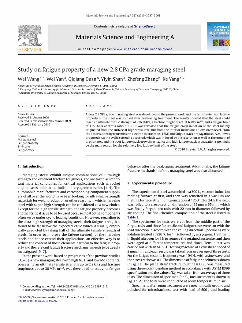
Fig. 3 shows the optical micrographs of the experimental steelafter peak aging at 500 ◦C for 2 h. The prior austenite grain size wasmeasured to be about 30 �m, and the steel had got full of low-carbon martensite structure without retained austenite, as shownin Fig. 3. Fig. 4 represents the TEM images of the peak-aged steel. Itcan be seen from the bright field image (Fig. 4a) that the microstruc-ture of the steel consisted of lath martensite with high density ofdislocations. The dark field image (Fig. 4b) shows that great dealsof needle-like precipitates in nanometer size well homogenouslydistributed in the matrix. It can be identified from the SAD pattern(as shown in Fig. 4c) that the precipitate should be a Ni3 (Mo, Ti)type phase. The un-dissolved coarse precipitates reported in otherstudies [9–11] such as �-(Fe, Co)7Mo6, �-Fe2Mo, Ni4Mo, were notfound in the matrix.
Table 2 lists the results of the tensile and plane strain fracturetoughness (KIC) tests on the maraging steel after peak-aging treat-ment. It can be seen that the ultimate tensile strength (UTS) could
reach over 2700 MPa due to the removal of the retained austenite atcryogenic temperature and the higher alloying in the steel. On theother hand, the fracture toughness did not fall down sharply andstill remained a relatively high level. The relationship between thew-carbon matensites; (b) prior austenite grains.
W. Wang et al. / Materials Science and Engineering A 527 (2010) 3057–3063 3059
F owingN
Uitiott
brs
ig. 4. TEM images of the maraging steel after peak-aging: (a) bright field image, shi3 (Mo, Ti) type phase; (c) PAD pattern of the matrix and precipitates.
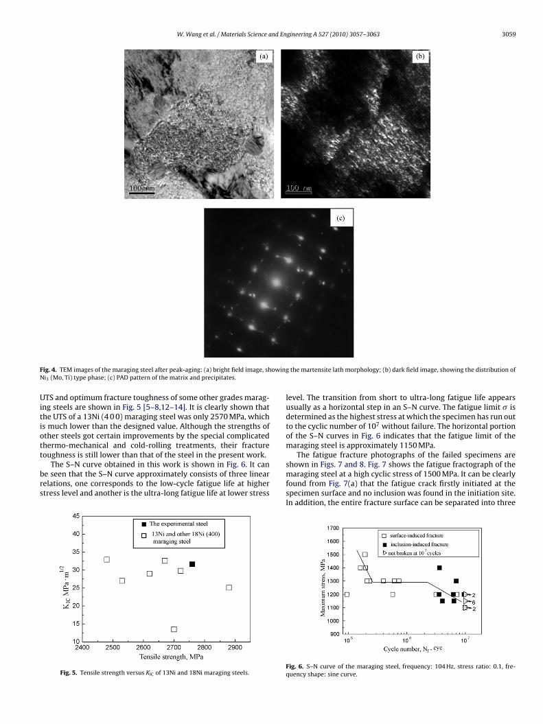
TS and optimum fracture toughness of some other grades marag-ng steels are shown in Fig. 5 [5–8,12–14]. It is clearly shown thathe UTS of a 13Ni (4 0 0) maraging steel was only 2570 MPa, whichs much lower than the designed value. Although the strengths ofther steels got certain improvements by the special complicatedhermo-mechanical and cold-rolling treatments, their fracture
oughness is still lower than that of the steel in the present work.The S–N curve obtained in this work is shown in Fig. 6. It cane seen that the S–N curve approximately consists of three linearelations, one corresponds to the low-cycle fatigue life at highertress level and another is the ultra-long fatigue life at lower stress
Fig. 5. Tensile strength versus KIC of 13Ni and 18Ni maraging steels.
the martensite lath morphology; (b) dark field image, showing the distribution of
level. The transition from short to ultra-long fatigue life appearsusually as a horizontal step in an S–N curve. The fatigue limit � isdetermined as the highest stress at which the specimen has run outto the cyclic number of 107 without failure. The horizontal portionof the S–N curves in Fig. 6 indicates that the fatigue limit of themaraging steel is approximately 1150 MPa.
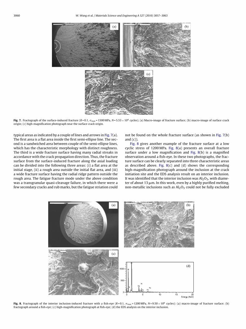
The fatigue fracture photographs of the failed specimens areshown in Figs. 7 and 8. Fig. 7 shows the fatigue fractograph of the
maraging steel at a high cyclic stress of 1500 MPa. It can be clearlyfound from Fig. 7(a) that the fatigue crack firstly initiated at thespecimen surface and no inclusion was found in the initiation site.In addition, the entire fracture surface can be separated into threeFig. 6. S–N curve of the maraging steel, frequency: 104 Hz, stress ratio: 0.1, fre-quency shape: sine curve.
3060 W. Wang et al. / Materials Science and Engineering A 527 (2010) 3057–3063
F .53 × 1o
tTowTasciarwf
Ff
ig. 7. Fractograph of the surface-induced fracture (R = 0.1, �max = 1500 MPa, N = 5rigin; (c) high-magnification photograph near the surface crack origin.
ypical areas as indicated by a couple of lines and arrows in Fig. 7(a).he first area is a flat area inside the first semi-ellipse line. The sec-nd is a sandwiched area between couple of the semi-ellipse lines,hich has the characteristic morphology with distinct roughness.
he third is a wide fracture surface having many radial streaks inccordance with the crack propagation direction. Thus, the fractureurface from the surface-induced fracture along the axial loadingan be divided into the following three areas: (i) a flat area at thenitial stage, (ii) a rough area outside the initial flat area, and (iii)
wide fracture surface having the radial ridge pattern outside theough area. The fatigue fracture mode under the above conditionas a transgranular quasi-cleavage failure, in which there were a
ew secondary cracks and rub marks, but the fatigue striation could
ig. 8. Fractograph of the interior inclusion-induced fracture with a fish-eye (R = 0.1,ractograph around a fish-eye; (c) high-magnification photograph at fish-eye; (d) the EDS
04 cycles). (a) Macro-image of fracture surface; (b) macro-image of surface crack
not be found on the whole fracture surface (as shown in Fig. 7(b)and (c)).
Fig. 8 gives another example of the fracture surface at a lowcyclic stress of 1200 MPa. Fig. 8(a) presents an overall fracturesurface under a low magnification and Fig. 8(b) is a magnifiedobservation around a fish-eye. In these two photographs, the frac-ture surface can be clearly separated into three characteristic areasas described above. Fig. 8(c) and (d) shows the correspondinghigh-magnification photograph around the inclusion at the crack
initiation site and the EDS analysis result on an interior inclusion.It was identified that the interior inclusion was Al2O3, with diame-ter of about 13 �m. In this work, even by a highly purified melting,non-metallic inclusions such as Al2O3 could not be fully excluded�max = 1200 MPa, N = 9.50 × 10⁶ cycles): (a) macro-image of fracture surface; (b)analysis on the interior inclusion.

nd En
itsatogrihtgiasfamti
wstsftof
Fdp
W. Wang et al. / Materials Science a
n the steel, as shown in Fig. 8. It is quite common for the heat-reated steels, especially those ultra-high strength steels, to haveome residual stress and even accumulate some hydrogen atomsround those non-metallic inclusions. It is also well known thathe coefficient of thermal expansion of Al2O3 is smaller than thatf the steel matrix, and the residual stress at the equator of such alobular inclusion is supposed to be tensile [15–17]. Based on theecent work [18,19], it has been directly verified by using secondaryon mass spectrometry that the interface of inclusions could trapydrogen atoms. They assumed that, as a result of superposition ofhe applied cyclic loading, residual stress and existence of hydro-en, the initiation and growth of cracks from internal non-metallicnclusions take place due to the hydrogen-assisted cracking. After
slow fatigue crack growth in the area beside the inclusion, theize of the crack can exceed a critical size given by the thresholdor pure fatigue propagation, and the crack will grow without thessistance of hydrogen by producing a fatigue surface in the typicalartensite lath microstructure. Therefore, it can be assumed that
he fatigue cracking of the present steel is an interior inclusion-nduced fracture at lower stress level.
In addition, the fatigue fracture surfaces of all the specimensere observed by SEM. It is found that the fatigue crack initiation
ites mainly originated either from the specimen surface or fromhe interior inclusions. It can be seen from Fig. 6, at high cyclictress level up about 1300 MPa, most the fatigue cracks initiated
orm the specimen surfaces; however, the fatigue cracks inclinedo originate from the interior inclusions at low cyclic stress levelf below 1300 MPa. This indicates that there is a clear transition ofatigue cracking initiation from surface to the interior at the criticalig. 9. TEM images and corresponding diffraction pattern of precipitates in the marageformation, size of precipitates was 5–10 nm; (b) dark field image, after 107 cycles derecipitates.
gineering A 527 (2010) 3057–3063 3061
cyclic stress level of about 1300 MPa. This critical cyclic stress levelshould be associated with the microstructure, size of inclusions,tensile strength as well as the loading mode or stress ratio.
Some researchers have reported the fatigue properties of marag-ing steels with different tensile strength levels [7,20–22]. Theseresults showed that the increase of tensile strength could not leadto an improvement of the fatigue properties, even after shot peen-ing or nitriding to the steels, and the fatigue strength was far belowthe expected value which was predicted empirically to be a halfof the ultimate tensile strength. Although the fatigue strength ofthe present steel was about 1150 MPa, lower but close to the halfof the tensile strength, it should be noted that the experiment wasconducted by the axial loading and the stress ratio was 0.1. If theGoodman relationship is used to equivalently transform the fatiguelimit tested with stress ratio of 0.1 to that with stress ratio of −1, thefatigue limit is found to be only 693 MPa, less than 30% of the ten-sile strength, as reported by others [23]. The poor fatigue propertyof maraging steels compared with their ultra-high tensile strengthmay be partly attributed to the detrimental effect of the water vaporin the ambient air or the rough surface conditions. However the rea-son for attributing the low fatigue strength of maraging steels notonly to the structural instability but also to the poor fatigue crackgrowth resistance may be clear from the following observationsand analyses.
First, comparison of the precipitates in the steel before and after
cyclic deformation revealed that the later showed an increase insize of the precipitates, especially after 107 cycles, as shown inFig. 9. The size of the precipitates before cycling was 5–10 nm, butexceeded 10 nm after 107 cycles, and the SAD showed that theing steel before and after cyclic deformation: (a) dark field image, before cyclicformation, precipitates were coarsened exceeding 10 nm; (c) PAD pattern of the

3 nd En
pmtppbhpsetsrcflcsdcst
stdmnsotfi
rrpsTiomCuamcs
062 W. Wang et al. / Materials Science a
recipitates were Ni3Mo intermetallic compounds which are theain hardening precipitates in maraging steels. It was reported
hat during the process of cyclic hardening and softening inrecipitation-hardened alloys the geometry and distribution ofrecipitates as well as the dislocation–particle interaction coulde altered by cyclic straining [5,7]. As one of typical precipitation-ardened alloys, maraging steels contain fine and closely spacedrecipitates which are coherent with the matrix and can be easilyheared by dislocations. It is generally believed that cyclic soft-ning is highly favored by this particularly interesting feature ofhese alloys. Therefore it can be considered that during the cyclicoftening of the present steel, cyclic straining could produce theesolution of some precipitates and the growth of some other pre-ipitates, the aggregation of Ni-rich precipitates would induce theormation of soft regions in which further deformation would beocalized and the probability of crack nucleation could be signifi-antly increased. The electron diffraction patterns of the peak-agedteel before and after cyclic deformation also showed that theiffraction spots of precipitates became scattering as a result ofycling. This phenomenon should be attributed to the high elastictresses around the precipitates, which might cause the diffractiono bend and rotate with respect to the matrix.
Van Swam et al. [7] studied the fatigue behavior of a 300eries maraging steel and found that the lower fatigue limit ofhe steel could be attributed to the extensive cyclic softeninguring fatigue process, with a mechanism of dislocation rearrange-ent and dislocation–precipitate interaction. Neither resolution
or growth of precipitates was clearly identified in their study. Ithould be noted that after 107 cycles, the ultimate tensile strengthf the present steel was found to decrease to 2543 MPa, 6% reduc-ion compared with that before the cyclic deformation, whichurther demonstrates the cyclic softening behavior in the exper-mental steel.
Regarding to the fatigue crack propagation behavior, it isemarkable that the steel showed a poor fatigue crack growthesistance, i.e., high fatigue crack growth rate. The fatigue crackropagation behavior in the steel was actually examined by a pul-ating stress ratio of 0.1 using compact tension (CT) specimens.he corresponding da/dN − �K obtained at 15 Hz in air is plottedn Fig. 10. Under the test condition, the crack growth evolutionbeyed a Paris law, i.e., da/dN = C �Km. The corresponding C and
values were measured to be 26.7 × 10⁻³² and 22.8, respectively.ompared with other high-strength steels [24–26], whose m val-
es are between 2.0 and 4.0, however, the present steel possessedmuch higher m value of 22.8. It is well known that higher m valueeans poor fatigue crack growth resistance and higher fatiguerack growth rate. Therefore it can be assumed that maraging steelshould behave in a similar fatigue crack propagation trend as TiAl
Fig. 10. Relationship between da/dN and �K.
[[[[[[
gineering A 527 (2010) 3057–3063
intermetallics or ceramics, i.e., once a fatigue crack originated, acatastrophic failure will easily take place. This also implies thatan increased yield stress obtained for highly alloyed ultra-high-strength steel does not always offer a substantial increase of thecrack growth resistance. In other words, the fatigue crack growthresistance of steels with very high yield strength may be relativelypoor. This phenomenon is of practical interest in view of selec-tion of an ultra-high-strength material for structural application.It has already been pointed out by other researchers [18,25,26]that high-strength materials are often sensitive to fatigue notch,and now it appears that the fatigue crack growth resistance of thematerial may be critical. Therefore the designers should considerthis aspect if they prefer to selecting a high-strength material forweight reduction or other reasons.
In summary, the current experimental results can be explainedthat the cyclic softening of maraging steels is due to the resolutionas well as the growth of precipitates in steels. The phenomenonof the multiplication and rearrangement of geometrically neces-sary dislocations, which can account for the monotonic hardeningand the cyclic softening behaviors, was not found. More exten-sive TEM observation needs to be performed in order to reveal themechanism of recovery from aging after the cyclic softening.
4. Conclusions
The main conclusions obtained from this study are summarizedas follows:
1. A new 2.8 GPa grade maraging steel has been developed, whichcould reach an ultimate tensile strength of 2760 MPa and a frac-ture toughness of 31.6 MPa m1/2.
2. The tension–tension fatigue property under peak-aging condi-tion for the steel was experimentally examined by axial loadingwith stress ratio of 0.1, and a fatigue limit of 1150 MPa wasobtained. Both the surface-induced fracture and the interiorinclusion-induced fracture were found in the S–N characteristicsof the steel.
3. The cyclic softening in the steel was confirmed by the enlargedsize of the precipitates and the decreased ultimate tensilestrength after cyclic deformation. The steel behaved in a poorfatigue crack growth resistance and high fatigue crack growthrate, i.e., the fatigue property of the steel was not as usuallyexpected.
Acknowledgements
The authors would like to thank Prof. Z.G. Wang and Mr. G. Yaofor their useful advices and experimental supports.
References
[1] K.V. Rajkumar, B.P.C. Rao, Mater. Sci. Eng. A 464 (2007) 233–240.[2] V. Vijayk, S.J. Kim, C. Marvin Wayman, Metall. Trans. A 21 (1990) 2655–2668.[3] F. Habiby, T.N. Siddiqui, H. Hussain, A. Ulhaq, A.Q. Khan, J. Mater. Sci. 31 (1996)
305–309.[4] F. Habiby, T.N. Siddiqui, H. Hussain, A. Ulhaq, A.Q. Khan, Mater. Sci. Eng. A 159
(1992) 261–265.[5] D.G. Lee, K.C. Jang, J.M. Kuk, I.S. Kim, J. Mater. Process. Technol. 162–163 (2005)
342–349.[6] K. Hussain, A. Tauqie, A. ul Haq, A.Q. Khan, Int. J. Fatigue 21 (1999) 163–168.[7] L.F. Van Swam, R.M. Pelloux, N.J. Grant, Metall. Trans. A 6 (1975) 45–53.[8] Y. He, Yangke, W. Qu, F. Kong, G. Su, Mater. Lett. 56 (2002) 763–769.[9] S. Floreen, G.R. Speich, Trans. ASM 57 (1964) 326–331.10] R. Tewari, S. Mazumder, I.S. Batra, et al., Acta Mater. 48 (2000) 1187–1200.
11] M. Michihiko, T. Setsuo, J. Soc. Mater. Sci. Jpn. 497 (1995) 181–186.12] M. Hagiwara, Y. Kawabe, Trans. ISIJ 21 (1981) 422–428.13] Y. Kawabe, S. Muneki, K. Nakazawa, H. Yaji, Trans. ISIJ 19 (1979) 238.14] T. Yasuno, K. Kuribayashi, T. Haseqawa, J. ISIJ 84 (1998) 55–60.15] Y. Murakami, T. Nomoto, T. Ueda, Fatigue Fract. Eng. Mater. Struct. 22 (1999)581–590.

nd En
[[
[[
[[
[
[23] T.H. Courtney, Mechanical Behavior of Materials, 2nd ed., McGRAW-Hill Com-
W. Wang et al. / Materials Science a
16] M. Nagumo, H. Uyama, M. Yoshizawa, Scr. Mater. 44 (2001) 947–952.17] Y. Murakami, T. Nomoto, T. Ueda, Fatigue Fract. Eng. Mater. Struct. 23 (2000)
893–910.
18] M.D. Chapetti, T. Tagawa, T. Miyata, Mater. Sci. Eng. A 356 (2003) 227–235.19] K. Takai, Y. Homma, K. Izutsu, M. Nagumo, J. Jpn. Inst. Met. 60 (1996)1155–1162.20] M. Michihiko, T. Setsuo, K. Noio, J. Soc. Mater. Sci. Jpn. 49 (2000) 631–637.21] M. Moriyama, T. Nagano, N. Kawagoishi, S. Takaki, J. Soc. Mater. Sci. Jpn. 50
(2001) 1126–1132.
[[
[
gineering A 527 (2010) 3057–3063 3063
22] U.K. Viswanathan, R. Kishore, M.K. Asundi, Metall. Mater. Trans. A 27 (1996)757–761.
panies, Inc., 1990, pp. 574–583.24] D.Y. Wei, J.L. Gu, H.S. Fang, B.Z. Bai, Z.G. Yang, Int. J. Fatigue 26 (2004) 437–442.25] T. Sakai, Y. Sato, Y. Nagano, M. Takeda, N. Oguma, Int. J. Fatigue 28 (2006)
1547–1554.26] A Carpinteri, Int. J. Fatigue 15 (1993) 21–26.