mathematical and experimental investigation of a …
TRANSCRIPT

MATHEMATICAL AND EXPERIMENTAL INVESTIGATION OF A DOWNDRAFT GASIFIER
Alexandre [email protected]
Ricardo da Silva [email protected]
Rafael Davidson Cova [email protected]
Thiago da Silva [email protected]
Taygoara Felamingo de [email protected]
Carlos Alberto Gurgel [email protected] of Brasília, Mechanical Engineering Department, Energy and Environment Laboratory, Brasília, DF, 70910-900.
Abstract.Brazil has a great potential for small-scale biomass gasification systems. Many locations in the Amazon region are deprived of electricity. Furthermore, the usage of small internal combustion engines, Diesel cycle, is widely spread. Reducing the consumption of diesel may be possible by burning low heating value gas produced in small-scale gasification units. This paper addresses a simplified designing method for biomass gasification reactor, which was validated by experimental investigation in a 1,300 cm3
spark ignition engine. An alternative approach, for dynamic performance investigation, is described. Despite the simplicity of the technology the results have shown a good performance of the system, which may become the ideal choice for remote areas electrification.Keywords: biomass gasification, downdraft gasifier, distributed generation
1. Introduction
Gasification in fixed bed is a promising technology for distributed energy in small scale, bellow 500 kWe, where the primary source is readily available, coal or biomass. Among many possible technologies, open top downdraft gasifier is suitable for generator set based on internal combustion engines. Stratified downdraft gasifiers are known to produce a cleaner gas, reducing thus the needs for complex after treatment of the combustible gas before final oxidation in the engine.
As pointed by Bridgwater (1995), the justification for biomass to be a major potential fuel and a renewable resource for Europe, classified as bioenergy includes:
security of long-term energy supplies; contribution for development of industrial markets; improvements of the environment by utilizing wastes and residues; making a positive contribution to limiting greenhouse effect; better management of surplus of agricultural and marginal land; provision of opportunities for socio-economic development of less-developed regions of Europe.
What was listed for Europe is also valid for Brazil. Particularly, the opportunity for socio-economic development of regions which are deprived of electricity, the importance is even far reaching.
This technology may be used to power remote civilizations in Brazil, such as villages and small communities in the main land where the conventional supplier cannot be found. For instance, thousands of small schools need electrification up to 20 kW. Table 1 lists the deficit in electrification for schools in different regions of the country.
Downdraft gasification may be a fuel supplier for spark and compression ignition engines. Most of the generator sets in the Northern parts of Brazil (Amazon region) are of the compression ignition type. With producer gas, the engine should operate in dual-mode, burning diesel as a pilot flame. The research in the field is covering the main aspects of the gasification technology, from modeling to experimental.
Warren et al. (1995) showed the feasibility of gasification plants on farm-sized scale using downdraft technology. A plant capable of delivering 30 kWe and 60 kW of heat, gasifying wood ships was tested with a spark-ignition engine. Lin and co-workers (1998) developed a rice husk gasification process. They concluded that for a 10 kW electricity
power a 28 kg/h of rice husk must be consumed in the gasification plant. The experiments were conducted in a laboratory-scale fixed bed and bench-scale downdraft gasifiers.
Midilli et al. (2001a) investigated the hydrogen production from hazelnut shells applying downdraft gasification technique. The research was conducted in a pilot scale 5 kW-throated downdraft gasifier. They concluded that hazelnut shells could be easily converted to hydrogen gas by applying downdraft gasification technology. Midilli and co-worker (2001b) also studied the production of combustible gas from sewage sludge with downdraft gasification. The average calorific value of the product gas was between 2.55 and 3.2 MJ (Nm3)-1. They considered sewage sludge a renewable energy source for gasifiers.
Table 1: Number of schools with and without electrification in Brazil (MEC, 1998).
Region schools with in site generator schools without electricity
North 1375 18776
Northeast 968 43627
East-Central 202 3207
Southeast 486 5849
South 117 1774
Total 3148 73233
Giltrap et al. (2003) presented a phenomenological model for downdraft gasification under steady state operation. The model predicted a product gas with a composition similar to that found experimentally, although over predicting methane concentration.
Jayah eta al. (2003) conducted computer simulation of a downdraft gasifier. He model consisted of two sub-models of the pyrolysis and gasification zones. They predicted that a wood ship size of 3-5 cm with moisture content below 15%, in a dry base, should be used in this type of gasifier.
Wander et al. (2004) conducted experiments in a fixed bed downdraft stratified and open top gasifier. The fuel consumption was around 12 kg/h and they proposed an internal gas recirculation which burn part of the gas to maintain a higher gasification reaction temperature. Bridging and channeling grate control combined to high wear of internal parts were the main operational problems faced.
Hanaoka and co-workers (2005) investigated the effect of woody components on air-steam gasification using a downdraft fixed-bed gasifier. Their experimental work suggested that information obtained in the gasification of separated wood components cold possibly be used to predict the composition product gas generated in air-steam gasification of biomass.
As it can be seen, biomass gasification has gained a great deal of importance by the scientific community. This work covers many aspects of biomass gasification with emphasis on the experimental investigation. A modeling procedure, employing empirical equations is presented and the SI engine performance, burning the producer gas, was estimated. Additionally, the paper will describe the status of the research on the numerical modeling of the reactor.
2. Mathematical Models
Two models are presented on this study. One is based partially on empirical correlation derived from the superficial velocity (Reed et al., 1999) or ratio of gas production rate to the cross sectional area (FID, 1986). The other method, presented briefly, is based on the integration of the partial differential equation by the finite volume method (Patankar, 1980). We start with the simplified model. Nonetheless, the reactions are valid for both and are listed here.
In biomass gasification the main oxidation reactions are
CxHy + a(O2 + 3,76N2) → (x+y/4)CO2 + (y/2)H2O + 3,76aN2 (R1)
In reaction 1, the hydrocarbon is in fact a mixture varying from light gases to what is collectively known as tar (high molecular weight).
Carbon monoxide and hydrogen are also, important components in the volatiles. Their homogeneous oxidation is
CO + H2 + 1,5(O2 + 3,76N2) → CO2 + H2O + 5,64N2 (R2)

The heat generated in the combustion of the pyrolysis gases is essential for the next step gasification reactions. The char formed from thermal degradation of the biomass is the source of carbon that is ultimately converted to producer gas. If primary source is char pyrolysis reactions are absent and the heat is produced by the following oxidation reaction
C + O2 → CO2 – 410 kJ/mol (R3)
In gasification the primary objective is to maximize the production of CO, H2 e CH4, typical constituents of producer gas. The main reduction reactions are
C + CO2 → 2CO + 164,9 kJ/mol (R4)
C + H2O → CO + H2 + 122,6 kJ/mol (R5)
C + 2H2 → CH4 + 0,0 kJ/mol (R6)
In the gas phase, some equilibrium reactions are key in the final composition of the gas, such as
CO + H2O ↔ CO2 + H2 - 42,3 kJ/mol (R7)
CO + 3H2 → CH4 + H2O - 205,9 kJ/mol (R8)
Based on the equilibrium reactions it is possible to estimate, to some degree of confidence, the average composition of the producer gas. Typical composition is given in Table 2 for biomass and coal gasification.
Table 2: Volumetric composition of producer gas (FID, 1986).
Gasifier Biomass (vol. %) Coal (vol. %)
Nitrogen – CH4 50 - 54 55 - 65
Carbon monoxide – CO 17 - 22 28 - 32
Carbon dioxide – CO2 9 - 15 1 - 3
Hydrogen – H2 12 - 20 4 - 10
Methane – CH4 2 - 3 0 - 2
Downdraft gasification is the primary choice for biomass gasification because the producer gas has low tar content. The gas is adequate to power generation systems, mostly internal combustion engines. The unit, thus was dimensioning to be burnt in a Otto cycle engine. In order to keep the unit in a small scale, the speed of the engine was limited to 3000 rpm.
Thermal efficiency of a gasification unit is an important parameter since it gives basic information on the sustainability of the power plant. Thermal efficiency can be estimated by
3 3[ / ] [ / ]100
[ / ] [ / ]g gas
gs bio
H kJ m V m s
H kJ kg m kg s
(1)
In Equation 1, Hg is the heat value of the producer gas, Vgas is the volumetric flow rate, Hs is the biomass heating value and mbio is the biomass consumption rate. The following is based on the theory for dimensioning a biomass gasifier based of superficial velocity.
Defining gasV as the amount of gas produced per unit time per cross sectional area. This value is normalized to the
atmospheric conditions. This parameter may be given as a function of converted biomass as2
[ ]biomkg
Vcm h
. Both can be
related assuming that for every kilogram of dry biomass, 2.5 m3 of gas is produced, then
3
2[ ] 2,5gas biom
mV V
cm h (2)
Typically, in downdraft gasification, the hearth load ranges from 0.4 to 0.5 m/s. With good thermal insulation these values can fall between 0.83 to 0.97 m/s. As pointed by Reed et al. (1999) modern gasifiers present superficial velocity in a broader range, as given in Table 2.
Designing a gasification unit starts by estimating the amount of gas necessary to run the power generation system. For system design and validation, we choose an internal combustion engine, with the following characteristics
Engine producer - Fiat; Otto cycle, four strokes; Bore [mm] = 76,0; Stroke [mm] = 71,5; Total volumetric capacity, CC =1,3 liters.
Table 3: Superficial velocity SV (m/s) for modern gasifiers (Reed et al. 1999).
Gasifier SV - PZ* SV - CZ* Gasifier SV - PZ SV - CZ
Imbert 0.63 2.5 Syn-gas air 1.71 1.71
Biomass Corp. 0.24 0.95 Syn-gas oxygen 1.07 1.07
SERI air 0.28 0.28 Buck Roger A 0.23 0.23
SERI oxygen 0.24 0.24 Buck Rogers B 0.13 0.13* PZ - pyrolysis zone, CZ - char zone.
A theoretical limit for engine gas intake is given by
3max
( )[ / ]
60 1000
rpm CCV m s
n
(3)
We set as the maximum engine speed as 3000 rpm, which will give for maximum engine charge 0.00325 m3/s.The actual equivalence ratio is given by
( / )
( / )est
real
A F
A F (4)
This parameter can only be calculated if the producer gas composition is known, to some degree of confidence. As a first approximation we assumed the composition of the gas based on that of Table 2. Accordingly, the oxidation reaction may given as
54N2 + 19CO + 12CO2 + 14H2 + 1CH4 + 18,5(O2 + 3,76N2) → 32CO2 + 16H2O + 123,6N2 (R9)
for which the air to fuel ratio is 0.97. One can assume that, for every kilogram of producer gas another kilogram of air is needed for complete combustion. Reaction 9 gives the necessary information on the amount of gas to be consumed by the engine assuming 80% volumetric efficiency. The unit should provide 49.68 m3/h of producer gas. The amount of biomass to run the gasification system is estimated as 20 kg/h. Considering a 25% thermodynamic efficiency of the spark ignition engine the power output of the gasification unit would be less than 17 kW.
Figure 1 shows the gasifier internal diameter as a function of superficial velocity for the specified internal combustion engine, up to 3000 rpm. Assuming that the gasifier is well insulated we chose a superficial velocity between 0.5 and 1.0 m/s. In this range the internal diameter for the reactor would be 150 mm.
We are implementing a dynamic modeling for the complex processes that take place in the reactor. Our approach is to integrate a set of partial differential equations through the finite volume method (Patankar, 1980). Basically, the model is similar to that proposed by Di Blasi (2000). The model is unsteady, one-dimensional, multiphase (solid and gas) and, due to the reactions considered, many chemical species are also balanced. Of great importance, the model will incorporated the best possible sub-models for pyrolysis, such as the Chemical Percolation Devolatilization Model (CPDNLG) of Grant et al. (1989). The same approach will be taken for the homogeneous and heterogeneous reactions.At this point, the model is solving the energy and momentum equation in porous media, isothermally. The sub-models regarding thermal degradation and overall reactions are being implemented and some predictions will be published soon.

3. Experimental Investigation
We built the system on a commercial ASTM 1020 tube with 144 mm. The unit was kept as simple as possible and. therefore, was comprised of a reactor, for gasification, and a scrubber for gas cleaning and cooling. Our primary objective in building such system was to validate the simplified theory for unit dimensioning. Also, for simplicity, we used charred biomass as the renewed energy source for the validation procedure. The length of the reactor was 460 mm. With this internal diameter, the operating superficial velocity is about 0.8 m/s. The reactor was filled with charred particle cylindrical shape, 2 to 3 cm in diameter and 3 to 5 cm long. After ignition the average time to have a producer gas capable of running the engine was from 10 to 17 minutes. Figure 2 shows the gasification unit.
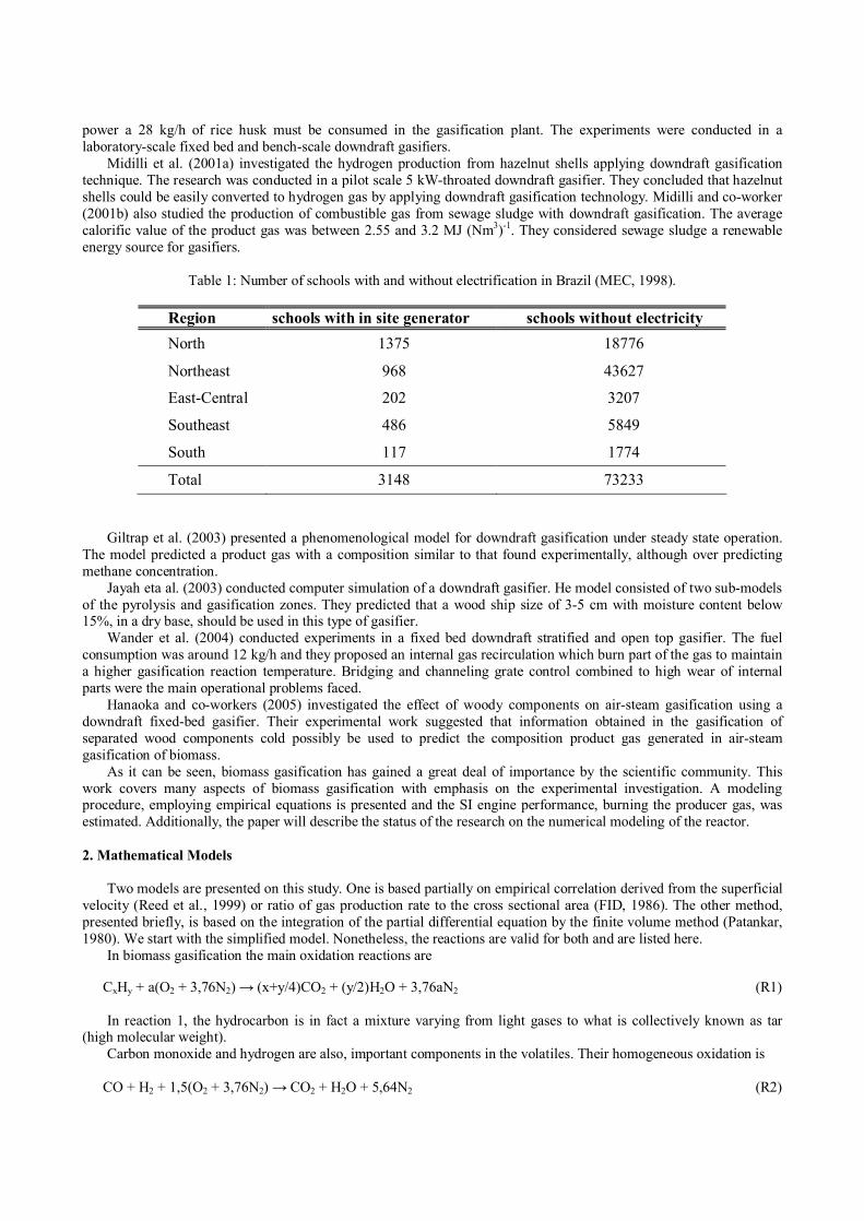
Figure 3 shows the power output versus engine speed, up to 2800 rpm. As it can be seen , the maximum power obtained was 10 kW. The system could not reach a stable operation at 3000 rpm, possibly due to a relatively small gasification reactor. The low efficiency of the cooling system also contributed to the unstable operation at this high speed.
We therefore, tested another gasification unit, with a larger internal diameter. In these tests we used biomass briquettes, 5.0 cm diameter and 10.0 cm long. The unit itself was the same as that shown in Fig. 2, but the reactor was 140 cm long and 280 cm internal diameter.
5
8
10
13
15
18
20
0.50 1.00 1.50 2.00 2.50
SV [m/s]
Gasif
ier
dia
me
ter
[cm
]
Figure 1. Gasifier internal diameter versus superficial velocity for the 1.3 cc engine.
water
Producer gas engine
ash
airbiomass
Figure 2. Schematic representation of the charred fuel gasification unit.
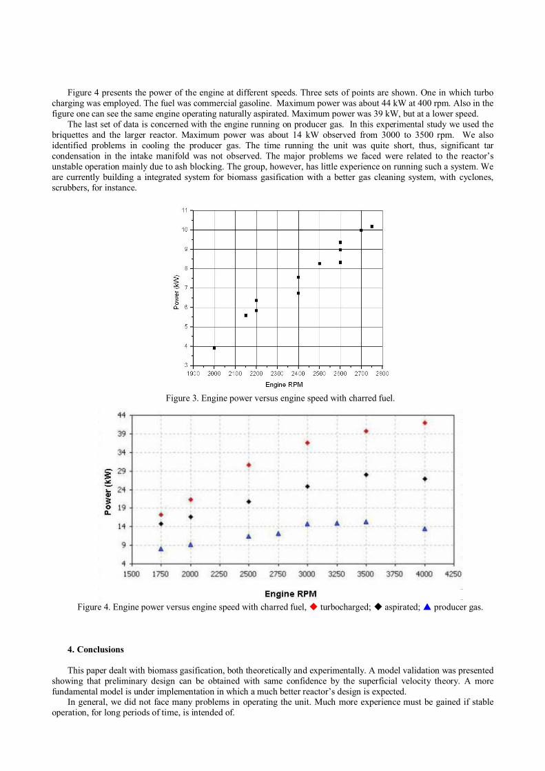
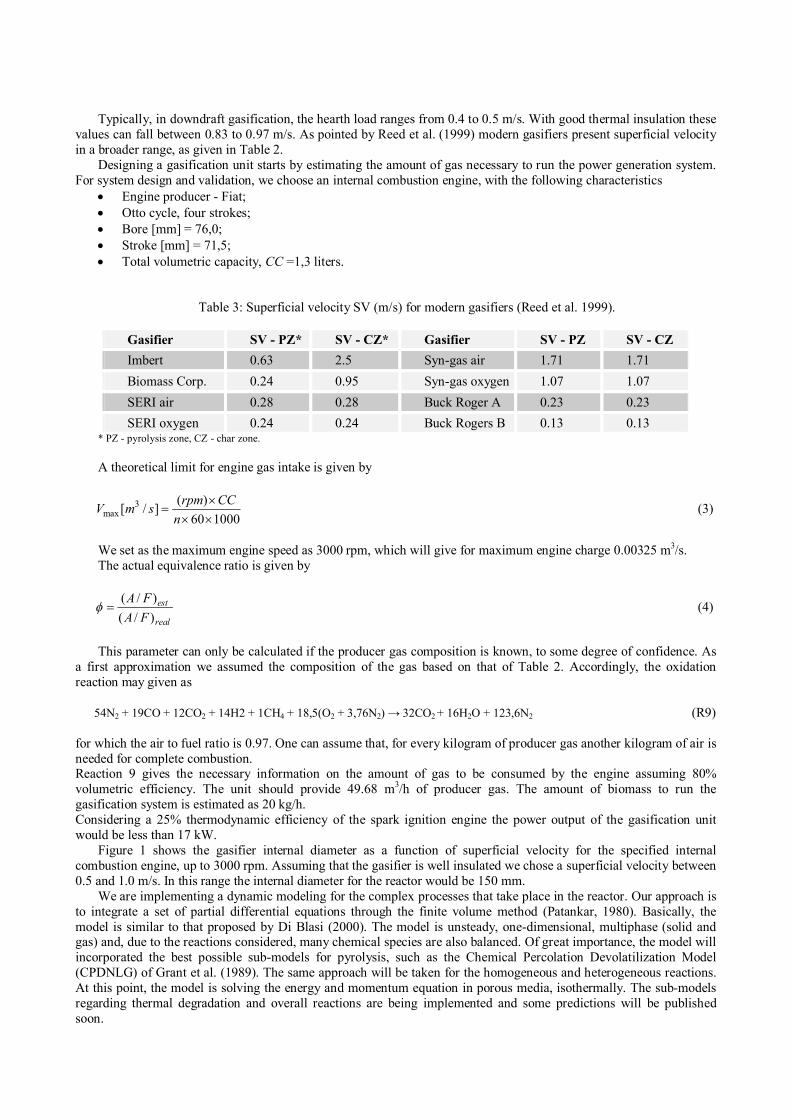
Figure 4 presents the power of the engine at different speeds. Three sets of points are shown. One in which turbo charging was employed. The fuel was commercial gasoline. Maximum power was about 44 kW at 400 rpm. Also in the figure one can see the same engine operating naturally aspirated. Maximum power was 39 kW, but at a lower speed.
The last set of data is concerned with the engine running on producer gas. In this experimental study we used the briquettes and the larger reactor. Maximum power was about 14 kW observed from 3000 to 3500 rpm. We also identified problems in cooling the producer gas. The time running the unit was quite short, thus, significant tar condensation in the intake manifold was not observed. The major problems we faced were related to the reactor’s unstable operation mainly due to ash blocking. The group, however, has little experience on running such a system. We are currently building a integrated system for biomass gasification with a better gas cleaning system, with cyclones, scrubbers, for instance.
Figure 3. Engine power versus engine speed with charred fuel.
Figure 4. Engine power versus engine speed with charred fuel, turbocharged; aspirated; producer gas.
4. Conclusions
This paper dealt with biomass gasification, both theoretically and experimentally. A model validation was presented showing that preliminary design can be obtained with same confidence by the superficial velocity theory. A more fundamental model is under implementation in which a much better reactor’s design is expected.
In general, we did not face many problems in operating the unit. Much more experience must be gained if stable operation, for long periods of time, is intended of.

5. Acknowledgements
The authors wish to tank ELETRONORTE – Brazil for the project grant.
6. References
Annual Report, Ministério da Educação e Cultura, 1998.Brigwater, A.V., The Technical and Economics Feasibility of Biomass Gasification for Power Generation, Fuel, 74, 5,
pp. 631-653, 1995.Di Blasi, C., Dynamic Behaviour of Startified Downdraft Gasifiers, Chemical Enginerring Science, 55, pp. 2931-2944,
2000.Forest Industry Division, Wood gas as engine fuel, FAO Forestry Department, 1986.Giltrap, D.L., McKibbin, R. and Barbes G.R.G., A Steady State Model of Gas-char Reactions in a Downdraft Biomass
Gasifier, Solar Energy, Vol. 74, pp. 85-91, 2003. Hanaoka, T., Inoue, S., Uno, S., Ogi, T. and Minow, T., Effect of Woody Biomass Componentes on Air-stema
Gasification, Biomass and Bioenergy, Vol. 28, pp. 69-76, 2005.Jayah, T.H., Aye, L., Fuller, R.J. and Stewart, D.F., Computer Simulation of a Downdraft Wood Gasifier for Tea
Drying, Biomass and Bioenergy, Vol. 25, pp. 459-469, 2003.Lin, K.S., Wang, H.P., Lin, C.-J. and Juch, C-I, A Process Development for Gasification of Rice Husk, Fuel Processing
Technology, Vol, 55, pp. 185-192, 1998.Midilli, A., Dogru, M., Howarth, C.R. and Ayhan, T., Hydrogen Production from Hazelnut Shell by Applying air-blown
downdraft Gasification Technique, International Journal of Hydrogen Energy, Vol. 26, pp. 29-37, 2001.Midilli, A., Dogru, M., Howarth, C.R., Ling, M.J. and Ayhan, T., Combustible Gas Production from Sewage Sludge
with a Downdraft Gasifier, Energy Conversion & Management, Vol. 42, pp. 157-172, 2001.Patankar, S.V. Numerical Heat Transfer and Fluid Flow. Hemisphere Publishing Corporation McGraw-Hill Book
Company, 1980. Wander, P.R., Altafini, C.R. and Barreto, R.M., Assessment of a Small Sawdust Gasification Unit, Biomass and
Bionergy, Vol. 27, pp. 467-476, 2003.