matlab /simulink dscs - microchip...
TRANSCRIPT
2011 Microchip Technology Inc. DS51771E
MATLAB®/Simulink®
Device Blocksets for dsPIC® DSCs
Note the following details of the code protection feature on Microchip devices:
• Microchip products meet the specification contained in their particular Microchip Data Sheet.
• Microchip believes that its family of products is one of the most secure families of its kind on the market today, when used in the intended manner and under normal conditions.
• There are dishonest and possibly illegal methods used to breach the code protection feature. All of these methods, to our knowledge, require using the Microchip products in a manner outside the operating specifications contained in Microchip’s Data Sheets. Most likely, the person doing so is engaged in theft of intellectual property.
• Microchip is willing to work with the customer who is concerned about the integrity of their code.
• Neither Microchip nor any other semiconductor manufacturer can guarantee the security of their code. Code protection does not mean that we are guaranteeing the product as “unbreakable.”
Code protection is constantly evolving. We at Microchip are committed to continuously improving the code protection features of ourproducts. Attempts to break Microchip’s code protection feature may be a violation of the Digital Millennium Copyright Act. If such actsallow unauthorized access to your software or other copyrighted work, you may have a right to sue for relief under that Act.
Information contained in this publication regarding deviceapplications and the like is provided only for your convenienceand may be superseded by updates. It is your responsibility toensure that your application meets with your specifications.MICROCHIP MAKES NO REPRESENTATIONS ORWARRANTIES OF ANY KIND WHETHER EXPRESS ORIMPLIED, WRITTEN OR ORAL, STATUTORY OROTHERWISE, RELATED TO THE INFORMATION,INCLUDING BUT NOT LIMITED TO ITS CONDITION,QUALITY, PERFORMANCE, MERCHANTABILITY ORFITNESS FOR PURPOSE. Microchip disclaims all liabilityarising from this information and its use. Use of Microchipdevices in life support and/or safety applications is entirely atthe buyer’s risk, and the buyer agrees to defend, indemnify andhold harmless Microchip from any and all damages, claims,suits, or expenses resulting from such use. No licenses areconveyed, implicitly or otherwise, under any Microchipintellectual property rights.
DS51771E-page 2
Trademarks
The Microchip name and logo, the Microchip logo, dsPIC, KEELOQ, KEELOQ logo, MPLAB, PIC, PICmicro, PICSTART, PIC32 logo, rfPIC and UNI/O are registered trademarks of Microchip Technology Incorporated in the U.S.A. and other countries.
FilterLab, Hampshire, HI-TECH C, Linear Active Thermistor, MXDEV, MXLAB, SEEVAL and The Embedded Control Solutions Company are registered trademarks of Microchip Technology Incorporated in the U.S.A.
Analog-for-the-Digital Age, Application Maestro, CodeGuard, dsPICDEM, dsPICDEM.net, dsPICworks, dsSPEAK, ECAN, ECONOMONITOR, FanSense, HI-TIDE, In-Circuit Serial Programming, ICSP, Mindi, MiWi, MPASM, MPLAB Certified logo, MPLIB, MPLINK, mTouch, Omniscient Code Generation, PICC, PICC-18, PICDEM, PICDEM.net, PICkit, PICtail, REAL ICE, rfLAB, Select Mode, Total Endurance, TSHARC, UniWinDriver, WiperLock and ZENA are trademarks of Microchip Technology Incorporated in the U.S.A. and other countries.
SQTP is a service mark of Microchip Technology Incorporated in the U.S.A.
All other trademarks mentioned herein are property of their respective companies.
© 2011, Microchip Technology Incorporated, Printed in the U.S.A., All Rights Reserved.
Printed on recycled paper.
ISBN: 978-1-60932-951-8
Microchip received ISO/TS-16949:2002 certification for its worldwide
2011 Microchip Technology Inc.
headquarters, design and wafer fabrication facilities in Chandler and Tempe, Arizona; Gresham, Oregon and design centers in California and India. The Company’s quality system processes and procedures are for its PIC® MCUs and dsPIC® DSCs, KEELOQ® code hopping devices, Serial EEPROMs, microperipherals, nonvolatile memory and analog products. In addition, Microchip’s quality system for the design and manufacture of development systems is ISO 9001:2000 certified.
MATLAB/SIMULINK DEVICE®
BLOCKSETS FOR dsPIC DSCsTable of Contents
Chapter 1. Deploying Device Blocksets1.1 Device Blocksets and the Microchip Target ................................................... 51.2 Installation Prerequisites ................................................................................ 91.3 Installation ...................................................................................................... 91.4 Licensing .......................................................................................................10
Chapter 2. MATLAB/Simulink Microchip Target Setup2.1 dsPIC DSC Configuration Blocks ................................................................. 112.2 dsPIC DSC Run-Time Library ...................................................................... 132.3 dsPIC33F DMC Algorithms .......................................................................... 152.4 dsPIC Q15 Math Library ............................................................................... 152.5 dsPIC DSC Floating Point C Math Library ................................................... 182.6 dsPIC DSP Library ....................................................................................... 192.7 dsPIC DSC SMPS Library ............................................................................ 20
Chapter 3. Creating Models using Device Blocksets3.1 Installing Device Blocks ................................................................................ 213.2 Using Device Blocks to Create a Model ....................................................... 213.3 Generating Code from a Model .................................................................... 21
Chapter 4. Device Blocks FAQs ................................................................................. 29
Appendix A. AN957 for dsPIC33F DSCs ExampleA.1 Hardware Setup ........................................................................................... 33A.2 Model Functionality Brief Description ........................................................... 33A.3 Software Functionality .................................................................................. 34A.4 Software Deviations ..................................................................................... 34A.5 Optimizations ............................................................................................... 34
Index ............................................................................................................................. 35
Worldwide Sales and Service .................................................................................... 38
2011 Microchip Technology Inc. DS51771E-page 3
MATLAB/Simulink Device Blocksets for dsPIC® DSCs
NOTES:
DS51771E-page 4 2011 Microchip Technology Inc.
MATLAB/SIMULINK DEVICE®
BLOCKSETS FOR dsPIC DSCsChapter 1. Deploying Device Blocksets
This chapter provides a device blocksets description, usage overview and installation instructions.
• Device Blocksets and the Microchip Target
• Installation Prerequisites
• Installation
• Licensing
1.1 DEVICE BLOCKSETS AND THE MICROCHIP TARGET
These MATLAB®/Simulink® device blocksets are specific to dsPIC® DSC peripherals. You can use them to develop and validate digital signal processing and control designs from concept through code.
You can create application models using these blocks along with Simulink library blocksets, and use the same for auto code generation.
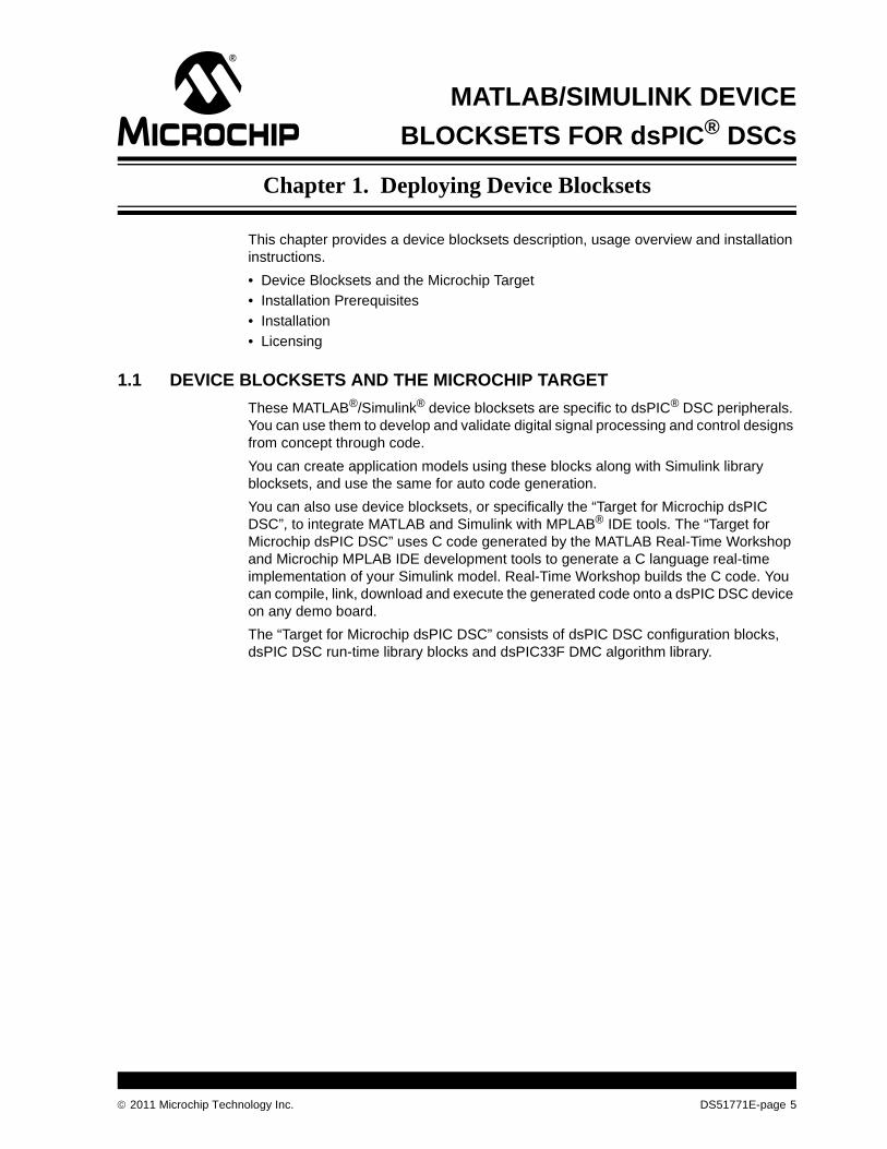
You can also use device blocksets, or specifically the “Target for Microchip dsPIC DSC”, to integrate MATLAB and Simulink with MPLAB® IDE tools. The “Target for Microchip dsPIC DSC” uses C code generated by the MATLAB Real-Time Workshop and Microchip MPLAB IDE development tools to generate a C language real-time implementation of your Simulink model. Real-Time Workshop builds the C code. You can compile, link, download and execute the generated code onto a dsPIC DSC device on any demo board.
The “Target for Microchip dsPIC DSC” consists of dsPIC DSC configuration blocks, dsPIC DSC run-time library blocks and dsPIC33F DMC algorithm library.
2011 Microchip Technology Inc. DS51771E-page 5
MATLAB/Simulink Device Blocksets for dsPIC® DSCs
FIGURE 1-1: TARGET FOR MICROCHIP dsPIC® DSC
DS51771E-page 6 2011 Microchip Technology Inc.
Deploying Device Blocksets
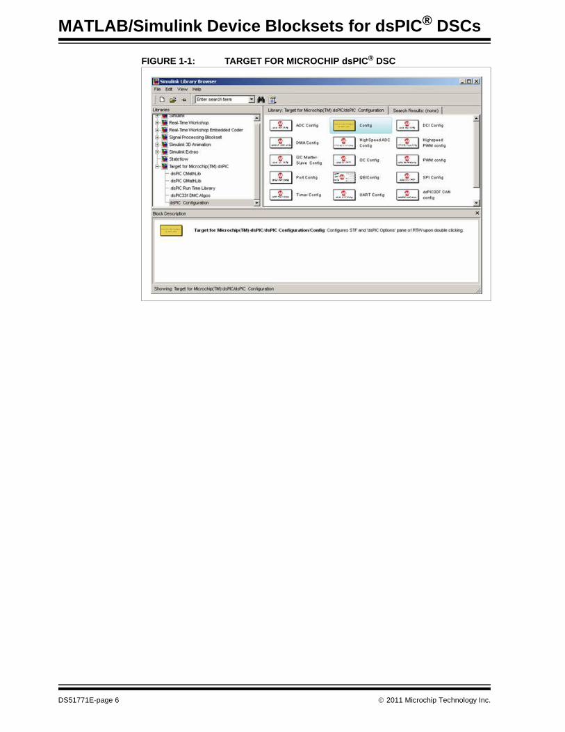
FIGURE 1-2: TARGET FOR MICROCHIP TOOLBOX LIBRARY
2011 Microchip Technology Inc. DS51771E-page 7
MATLAB/Simulink Device Blocksets for dsPIC® DSCs
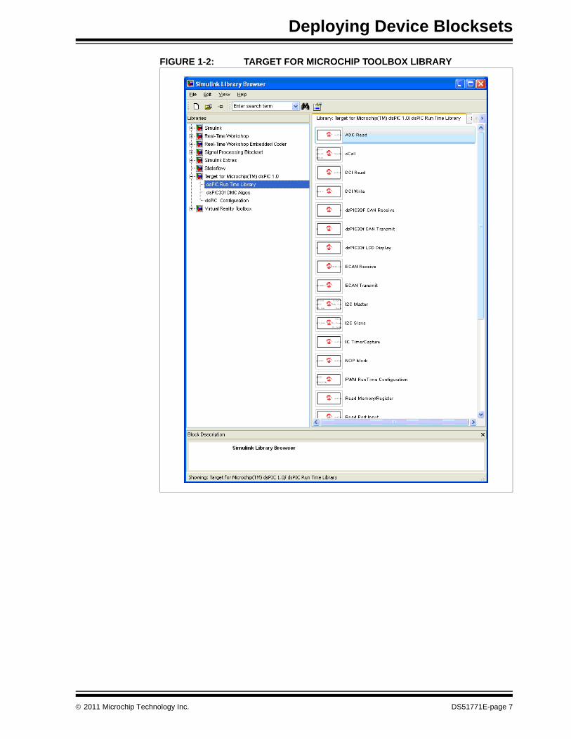
FIGURE 1-3: dsPIC33F DMC ALGORITHMS
DS51771E-page 8 2011 Microchip Technology Inc.
Deploying Device Blocksets
1.2 INSTALLATION PREREQUISITES
You need to have MATLAB vR2007a or later. Your MATLAB License should have following products:
• Simulink
• Real-Time Workshop
• Real-Time Embedded Coder
You may also want the MPLAB C Compiler for PIC24 MCUs and dsPIC DSCs (from Microchip) to generate hex files from the models. Recommended compiler versions are 3.12, 3.21 or later.
If you don't have this compiler installed, you can only generate code from your models.
1.3 INSTALLATION
1. Back up any of the models that you might have created using older versions of “Target for Microchip dsPIC DSC”.
2. Uninstall older version(s) of “Target for Microchip dsPIC DSC” by running remove_dsPIC_Matlab.p or remove_dsPIC_Matlab.m available in your installation.
3. Run the installer of Microchip Device Blocksets, dsPIC-MATLAB-Blocksets_v2_XX.exe.Microchip device blocks will install inside the folder that you have chosen.
4. Browse to the file dsPIC_Matlab_Install.p in your MATLAB file browser, right click on it and run it. Please do not try to open Install_dsPIC_Matlab.p or your MATLAB installation may not be able to open it.
5. To uninstall, run remove_dsPIC_Matlab.p (Recommended). Alternatively, if you would like to uninstall manually, you will need to remove all paths related to the blocksets from the MATLAB search paths and then delete relevant folders.
The “Target for Microchip dsPIC DSC” consists of following folders:
• dspic: contains system target files and TMFs which are required for the build
• dspicblks: files supporting blocksets
• demomodels: demo models
• blockSkins: folder that has images for blocks
• doc: documentation and help files that support online help
• MicroDetails: device database files in MATLAB format
• Sources: block-specific support files
• Plug-In Scripts: scripts related to the MATLAB plug-in in MPLAB IDE
2011 Microchip Technology Inc. DS51771E-page 9
MATLAB/Simulink Device Blocksets for dsPIC® DSCs
1.4 LICENSING
The blocksets work with full features even if you do not have a license. However, every time you build the model to generate code, you will experience a 30 second delay. To remove the delay and to receive prioritized support from Microchip, you need to buy and install a license.
Contact Microchip to get a license key. Once you have the key, you will need to register it using the registration utility of the MATLAB plug-in available in MPLAB IDE.
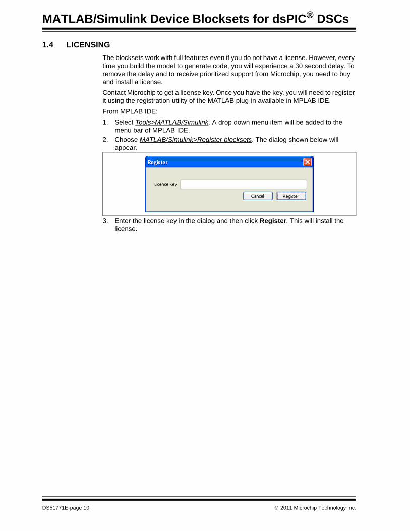
From MPLAB IDE:
1. Select Tools>MATLAB/Simulink. A drop down menu item will be added to the menu bar of MPLAB IDE.
2. Choose MATLAB/Simulink>Register blocksets. The dialog shown below will appear.
3. Enter the license key in the dialog and then click Register. This will install the license.
DS51771E-page 10 2011 Microchip Technology Inc.
MATLAB/SIMULINK DEVICE®
BLOCKSETS FOR dsPIC DSCsChapter 2. MATLAB/Simulink Microchip Target Setup
The blocksets have been grouped under different libraries listed below:
• dsPIC DSC Configuration Blocks
• dsPIC DSC Run-Time Library
• dsPIC33F DMC Algorithms
• dsPIC Q15 Math Library
• dsPIC DSC Floating Point C Math Library
• dsPIC DSP Library
2.1 dsPIC DSC CONFIGURATION BLOCKS
Configuration blocks generally form the initialization part of any application. For information on each block, click the Help button on that dialog.
2.1.1 dsPIC30FXX/33FXX Main
This is the device configuration block for dsPIC30F or dsPIC33F devices. Every model that you create must have one device configuration block. You can configure the oscil-lator, select the looping timer, etc., using this block. One model is not allowed to have more than one device configuration block.
2.1.2 ADC Config
The Analog-to-Digital Converter (ADC) block configures the device ADC to perform the analog-to-digital conversion of signals connected to the selected ADC input pins. The ADC block outputs digital values representing the analog input signal and stores the converted values in the result register of your digital signal processor. You use this block to capture and digitize analog signals from external sources such as signal generators, frequency generators or audio devices.
Related dialogs: ADC Read
2.1.3 ECAN™ Config
This block configures the ECAN module.
Limitations of the ECAN module device block:
1. Currently, the DeviceNet™ filter bits are not used.
2. The reception of ECAN messages using the FIFO is not tested. Therefore, the code generation verification is not done for this section.
3. It is the user’s responsibility to create the values of Phase Segment 1, 2 and SJW.
4. Interrupt handling is not covered for either data reception/transmission or for error handling.
5. Only the polling mode of ECAN is implemented. There is no interrupt mode handling.
Related dialogs: ECAN Receive Block, ECAN Transmit Block
2011 Microchip Technology Inc. DS51771E-page 11
MATLAB/Simulink Device Blocksets for dsPIC® DSCs
2.1.4 DCI Config
This is the DCI block configuration the device.
Related dialogs: DCI Read, DCI Write
2.1.5 DMA Config
This is the DMA block configuration for the dsPIC DSCs. This block can configure all 8 DMA channels as per your configuration. You have to check ‘Channel X enable’ if you want to enable channel X. X can be 0,1,2….7.
2.1.6 I2C Config
This configures the Inter-Integrated Circuit (I2C™) operation.
Related dialogs: I2C-Master, I2C-Slave
2.1.7 IPCTimerCapture Config
This configures the ‘Input Capture’ peripheral. It captures the timer value from the specified timer.
2.1.8 OC Config
This configures the output compare peripheral. It compares OCxR with the timer specified and generates the appropriate output.
2.1.9 PWM Config
This block configures the PWM module in dsPIC DSC devices with motor control PWM. Frequencies which result in incompatible values of the PWM frequency and FCY clock frequency are caught as errors. Duty cycles can be mentioned as percentages rather than the values in the registers.
Limitations of the PWM module device block:
1. Configuration is tested for Free Running mode only. No other modes of operation are tested.
2. Dead-time control, output override control, Fault control using an external pin, special event compare and post scaling are not supported.
3. PWM update disable support (UDIS bit) is not provided.
4. Dynamic changes to the duty cycle are not currently provided.
5. Interrupt routines and interrupt handling are not provided.
2.1.10 QEI Config
This configures Quadrature Encoder Interface (QEI) operation.
2.1.11 SPI Config
The SPI block configures the device SPI 1 or 2.
Related dialogs: SPI Transmit, SPI Receive
DS51771E-page 12 2011 Microchip Technology Inc.
MATLAB/Simulink Microchip Target Setup
2.1.12 Timer Config
This configures the timer selected. Timer2-3, 4-5, 6-7 and 8-9 can be combined to form 32-bit timers.
Limitations of the Timer1 module device block:
• Make sure that the timer being enabled is not being used for the main loop in the device config block.
2.1.13 UART Config
The UART block configures the device UART 1 or 2.
Related dialogs: UART Transmit, UART Read
2.1.14 Port Config
This is Port Configuration block for the dsPIC DSCs. This block can configure different ports, its direction Input/Output and can even configure selected port pins as per your configuration.
Related Dialog: Port Read, PortWrite.
2.2 dsPIC DSC RUN-TIME LIBRARY
Run-time blocks generally form the run-time part of any application. For information on each block, click the Help button on that dialog.
2.2.1 ADC Read
This block tells the ADC from which ADC buffer to read.
2.2.2 CAN Receive/Transmit
All the set up for the CAN receive is done in the CAN configuration. The CAN receive block receives and provides the raw data that it receives on a particular module irrespective of the CAN message which delivers it.
Care should be exercised when selecting the transmit buffer for CAN transmit. A single buffer should not be used for reception and transmission according to the current design of the underlying device driver.
2.2.3 DCI Read/Write
These blocks read or write data received by or transmitted to the DCI buffer, respectively. You need to provide the buffer number from 0-3.
2.2.4 I2C Master/Slave
These blocks configure the I2C modules to operate as Master/Slave. Baud rate, mode, parity, etc., can be chosen using these blocks.
2.2.5 LCD Display – dsPIC33F DSCs
The block writes each character supplied to it on to the LCD. The LCD feature is cur-rently supported only for the dsPIC33FJXXXMC710 and dsPIC33FJXXXGP710 devices of the dsPIC33F DSC family.
The Explorer 16 board includes an alphanumeric LCD display with two lines of 16 char-acters each. The display is driven with three control lines (RD4, RD5 and RD15) and eight data lines (RE7:RE0).
2011 Microchip Technology Inc. DS51771E-page 13
MATLAB/Simulink Device Blocksets for dsPIC® DSCs
2.2.6 Memory/Register Read/Write
Read Memory/Register is a run-time block used for reading from a specified memory location or SFR. You need to enter a hex address (in case of memory read), or an SFR name in capital letters (in case of an SFR read).
Write Memory/Register is a run-time block used for writing into a specified memory location or SFR. You need to enter a hex address (in case of a memory write), or an SFR name in capital letters (in case of an SFR write).
2.2.7 NOP Block
Introduces a delay of as many clock cycles as mentioned. The input is provided at the output port after a specified number of NOPs.
2.2.8 Port Read/Write
Reads from the specified port. You can specify whether a byte or individual bits have to be read. To indicate which bit or bits need to be read, specify the bit’s number starting from bit 0. For example, [0:3] will indicate bits 0-3; [7] will indicate bit 7.
Writes to the specified port. You can specify whether a byte or individual bits have to be written. If you want to write to individual bits, you can specify the bit’s number that you wish to write, starting from bit 0. For example, [0:3] indicates bits 0-3.
2.2.9 PWM Runtime Config
This block takes two inputs: PWM_DC and OVDCON (both are unit16 data type). No configuration needs to done through the mask GUI. PWM_DC is the PWM duty cycle required, and OVDCON is the override configuration.
2.2.10 SPI Transmit/Receive
This block defines from which SPI to transmit and from which SPI to receive.
2.2.11 UART Transmit/Receive
This block defines from which UART to transmit and from which UART to receive.
DS51771E-page 14 2011 Microchip Technology Inc.
MATLAB/Simulink Microchip Target Setup
2.3 dsPIC33F DMC ALGORITHMS
The dsPIC33F DMC algorithms are the motor control algorithm blocks. They can be used for code generation and simulation. When used for code generation, they gener-ate optimized code for customization using dsPIC33F devices.
2.3.1 dspic33fxx_ClarkeTransform
This block performs the Clarke Transform, which moves a three-axis, two-dimensional coordinate system, referenced to the stator, onto a two-axis system, keeping the same reference.
2.3.2 dspic33fxx_InvClarkeTransform
This block performs the Inverse Clarke Transform, which moves a two-axis system onto a three-axis, two-dimensional coordinate system, referenced to the stator keeping the same reference.
2.3.3 dspic33fxx_ParkTransform
This block performs the Park Transform, which converts quantities represented in a two-axis orthogonal system with the axis called - into another two-axis system that is rotating with the rotor flux. This two-axis rotating coordinate system is called the d-q axis.
2.3.4 dspic33fxx_InvParkTransform
This block performs the Inverse Park Transform, which converts quantities represented in two-axis system that is rotating with the rotor flux into another two-axis orthogonal system with the axis called - .
2.3.5 dspic33fxx_PIControl
PI (Proportional Integral) implementation is conventional and includes the term (Kc*Excess) to limit integral windup. Excess is calculated by subtracting the unlimited output (U) and limited output (Out). The term Kc multiplies the Excess, and limits the accumulated integral portion (Sum).
2.3.6 dspic33fxx_SpaceVectorGen
This block performs the Space Vector Generation action. It generates the PWM from three individual phase components in the 3-axis form obtained by Clarke transforms.
2.3.7 dspic33fxx_SMC
This block performs the Slide motor control action.
Note: For additional information, refer to AN1078, “Sensorless Field Oriented Control of PMSM Motors” (DS01078).
2011 Microchip Technology Inc. DS51771E-page 15
MATLAB/Simulink Device Blocksets for dsPIC® DSCs
2.4 dsPIC Q15 MATH LIBRARY
These are commonly-used mathematical functions. They can be used for code gener-ation and simulation. When used for code generation, they generate optimized code with a Q15 integer data type for chosen dsPIC DSC devices. Inputs to these blocks should be fixed point numbers in Q15 format, which ranges from -215 to 215-1. For more details on these functions, please refer to “Chapter 5. Fixed Point Math Func-tions” of the document 16-Bit_Language_Tools_Libraries_51456E.pdf in your complier documentation folder (C:\Program Files\Microchip\MPLAB C30\docs by default)
2.4.1 dsPIC Q15Abs
This block computes the absolute value of a Q15 input.
2.4.2 dsPIC Q15ACos
This block calculates the inverse cosine of a Q15 input and divides it by PI (). Input should be a fixed point number in Q15 format, which ranges from -215 to 215-1. The value of this argument ranges from -32768 to 32767. Output also is a Q15 number vary-ing from 82 to 32767.
2.4.3 dsPIC Q15Add
This block adds the two Q15 inputs. Inputs should be fixed point numbers in Q15 for-mat.
2.4.4 dsPIC Q15ASin
This block calculates the inverse sine of a Q15 input and divides it by PI (). Input should be a fixed point number in Q15 format, which ranges from -215 to 215-1. The value of this argument ranges from -32768 to 32767. Output also is a Q15 number vary-ing from -16384 to 16303.
2.4.5 dsPIC Q15ATan
This block calculates the inverse tangent of a Q15 input and divides it by PI (). Input should be a fixed point number in Q15 format, which ranges from -215 to 215-1. The value of this argument ranges from -32768 to 32767. Output also is a Q15 number vary-ing from -8192 to 8192.
2.4.6 dsPIC Q15Cos
This block calculates the cosine of PI () times a Q15 input. Input should be a fixed point number in Q15 format, which ranges from -215 to 215-1. The value of this argu-ment ranges from -32768 to 32767. Output also is a Q15 number varying from -32768 to 32767.
2.4.7 dsPIC Q15Exp
This block computes the exponential of a Q15 input. Input should be a fixed point num-ber in Q15 format, which ranges from -215 to 215-1.
2.4.8 dsPIC Q15Ftoi
This block converts a single-precision floating-point value into its corresponding Q15 value. Input should be a single-precision floating-point number, which ranges from -1 to 0.99996. The value of output ranges from -32768 to 32767.
DS51771E-page 16 2011 Microchip Technology Inc.
MATLAB/Simulink Microchip Target Setup
2.4.9 dsPIC Q15Log10
This block computes the logarithm (base 10) of a Q15 input. Input should be fixed point numbers in Q15 format, which ranges from -215 to 215-1.
2.4.10 dsPIC Q15Log
This block computes the natural logarithm of a Q15 input. Input should be a fixed point number in Q15 format, which ranges from -215 to 215-1.
2.4.11 dsPIC Q15Pow
This block computes Q15 input1 raised to the power of Q15 input2. Inputs should be fixed-point numbers in Q15 format, which range from -215 to 215-1. The value of this argument ranges from -32768 to 32767.
2.4.12 dsPIC Q15Rand
This block computes a random number in Q15 format, which ranges from -215 to 215-1.
2.4.13 dsPIC Q15Shl
This block left-shifts the first Q15 input by a number of bits represented by the second Q15 input. Inputs should be fixed-point numbers in Q15 format, which range from -215 to 215-1. The value of this argument ranges from -32768 to 32767.
2.4.14 dsPIC Q15Shr
This block right shifts first Q15 input by a number of bits represented by Q15second input. Inputs should be fixed point numbers in Q15 format, which ranges from -215 to 215-1. the value of this argument ranges from -32768 to 32767.
2.4.15 dsPIC Q15Sin
This block calculates the sine of PI () times a Q15 input. Input should be a fixed-point number in Q15 format, which ranges from -215 to 215-1. The value of this argument ranges from -32768 to 32767.
2.4.16 dsPIC Q15Sqrt
This block computes the square root of a Q15 input. Input should be fixed-point number in Q15 format, which ranges from -215 to 215-1.
2.4.17 dsPIC Q15Sub
This block subtracts the first Q15 input from the second Q15 input. Inputs should be fixed-point numbers in Q15 format, which range from -215 to 215-1. The value of this argument ranges from -32768 to 32767.
2.4.18 dsPIC Q15Tan
This block calculates the tangent of PI () times a Q15 input. Input should be a fixed-point number in Q15 format, which ranges from -215 to 215-1. The value of this argument ranges from -32768 to 32767.
2011 Microchip Technology Inc. DS51771E-page 17
MATLAB/Simulink Device Blocksets for dsPIC® DSCs
2.5 dsPIC DSC FLOATING POINT C MATH LIBRARY
These are commonly-used mathematical functions. They can be used for code gener-ation and simulation. When used for code generation, they generate optimized code with a Q15 integer data type for chosen dsPIC DSC devices. Inputs to/Outputs from these blocks should be single or double precision floating point numbers. For more details on these functions, please refer to “Chapter 3. Standard C Libraries - Math Functions” of document 16-Bit_Language_Tools_Libraries_51456E.pdf in your complier documentation folder (C:\Program Files\Microchip\MPLAB C30\docs by default)
2.5.1 CMathAbs
This block computes absolute value of a floating point input.
2.5.2 CMathACos
This block computes the trigonometric arc cosine function of a single/double precision floating point input.
2.5.3 CMathASin
This block computes the trigonometric arc sine function of a single/double precision floating point input.
2.5.4 CMathATan
This block computes the trigonometric arc tangent function of a single/double precision floating point input.
2.5.5 CMathCos
This block computes the trigonometric cosine function of a single precision floating point input.
2.5.6 CMathExp
This block computes exponential function of x (e raised to the power x) where x is a single precision floating point input.
2.5.7 CMathMod
This block calculates the remainder of x/y as a single/double precision value where x and y are single/double precision floating point inputs.
2.5.8 CMathLog
This block computes the logarithmic (base 10) value of a single/double precision floating point input.
2.5.9 CMathPow
This block calculates x raised to the power y, where x and y are single/double precision floating point values.
2.5.10 CMathRound
This block computes the ceiling/floor value of a single/double precision floating point input.
DS51771E-page 18 2011 Microchip Technology Inc.
MATLAB/Simulink Microchip Target Setup
2.5.11 CMathSin
This block computes the trigonometric sine function of a single/double precision float-ing point input.
2.5.12 CMathSqrt
This block computes the square root of a single/double precision floating point input.
2.5.13 CMathTan
This block computes the trigonometric tangent function of a single/double precision floating point input.
2.6 dsPIC DSP LIBRARY
These are commonly used DSP functions. They can be used for code generation only. Simulation is not currently supported. For more details on these functions, please refer to the DSP Library.htm document in your complier documentation folder (C:\Program Files\Microchip\MPLAB C30\docs\dsp_lib by default).
2.6.1 dsPIC ComplexFFT32
This block computes the Fast Fourier Transform of a source complex vector and stores the result in the destination complex vector as per configuration.
2.6.2 dsPIC ComplexIFFT32
This block computes the Inverse Fast Fourier Transform of a source complex vector and stores the result in the destination complex vector as per configuration.
2.6.3 dsPIC FIR
This block performs FIR filtering of a source real vector and stores the results in the destination complex vector as per configuration.
2.6.4 dsPIC RealFFT32
This block computes the Fast Fourier Transform of a source real vector and stores the results in the destination complex vector as per configuration.
2.6.5 dsPIC RealIFFT32
This block computes the Inverse Fast Fourier Transform of a source real vector and stores the results in the destination complex vector as per configuration.
2.6.6 dsPIC Squared Magnitude
This block computes the squared magnitude of a complex source vector and stores the results in the destination complex vector as per configuration.
2011 Microchip Technology Inc. DS51771E-page 19
MATLAB/Simulink Device Blocksets for dsPIC® DSCs
2.7 dsPIC DSC SMPS LIBRARY
This library has 2 parts: a simulation library and a code generation library. The simula-tion library has blocks which can be used to calculate gains of various SMPS topologies based on user input data. The code generation library contains blocks which can be used to generate code for various topologies. For more details, please look up the demo models provided under DemoModels/SMPSDemos.
2.7.1 dsPIC DSC SMPS Simulation Library
The simulation library has blocks which can be used to calculate gains of various SMPS topologies based on user input data. You need to input the topology parameters. The block computes gain coefficients and then uses them while simulating. The same gain coefficients can be used for code generation.
2.7.1.1 DCDC SINGLEPHASE BUCK
Simulates DC_DC Single phase buck Converter.
2.7.1.2 DCDC MULTIPHASE BUCK
Simulates DC_DC Multi phase buck Converter.
2.7.1.3 OFFLINEUPS CMC INVERTER
Simulates Offline UPS.
2.7.1.4 LLC HALFBRIDGE CONVERTER
Simulates LLC Half Bridge Converter.
2.7.1.5 ZVT CMC CONVERTER
Simulate ZVT CMC Converter.
2.7.2 dsPIC DSC SMPS Code Generation Library
The code generation library contains blocks which can be used to generate code for various topologies. You need to configure the gain coefficient parameters. These parameters can be calculated using the corresponding blocks from SMPS Simulation Library.
2.7.2.1 DCDC BUCK
Generates code for Single phase and multiphase buck Converter.
2.7.2.2 OFFLINEUPS CMC INVERTER
Generates code for Offline UPS.
2.7.2.3 LLC HALFBRIDGE CONVERTER
Generates code for LLC Half Bridge Converter.
2.7.2.4 ZVT CMC CONVERTER
Generates code for ZVTT CMC Converter.
DS51771E-page 20 2011 Microchip Technology Inc.
MATLAB/SIMULINK DEVICE®
BLOCKSETS FOR dsPIC DSCsChapter 3. Creating Models using Device Blocksets
Creating and using models require the following steps:
• Installing Device Blocks
• Using Device Blocks to Create a Model
• Generating Code from a Model
3.1 INSTALLING DEVICE BLOCKS
The Microchip device blocksets are distributed as a separate library package, so you need to install them separately from your MATLAB installation. Once you install the “Target for Microchip dsPIC DSC”, these blocksets would appear in your Simulink Library tree. Refer to Chapter 1. “Deploying Device Blocksets” for installation details.
3.2 USING DEVICE BLOCKS TO CREATE A MODEL
Models are created by placing the relevant device blocks with required sources and sinks (from Simulink Library) in a new model file (see Chapter 2. “MATLAB/Simulink Microchip Target Setup” for functional details of the blocks). This model would have the ‘config’ blocks for all the peripherals which will be used. Add the ‘Double-Click to Configure for dspic_stf.tlc’ block to configure the right tlc and compiler toolchain.
3.3 GENERATING CODE FROM A MODEL
The two ways to generate code from Simulink models are:
1. Once the model is built, the MATLAB plug-in for MPLAB IDE may be used for code generation as specified in the MATLAB/Simulink Help file. This creates an archive library which has to be linked with code generated. If MATLAB versions R2007b or R2007a are used, you may experience following issues:
a) Code generation takes a long time, even for simple models.
b) A lot of “dummy” C files are generated, which increases the total build time.
c) The large number of files takes a long time to import into an MPLAB IDE workspace.
2. Code may be generated using the real-time workshop of MATLAB. Code gener-ated has to be built after including the necessary peripheral library files and wrap-per header files used for creating device blocks. This will generate the COFF file which can be flashed on a device.
To create a Simulink model from device blocks:
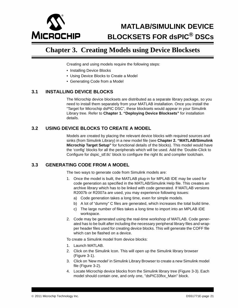
1. Launch MATLAB.
2. Click on the Simulink Icon. This will open up the Simulink library browser (Figure 3-1).
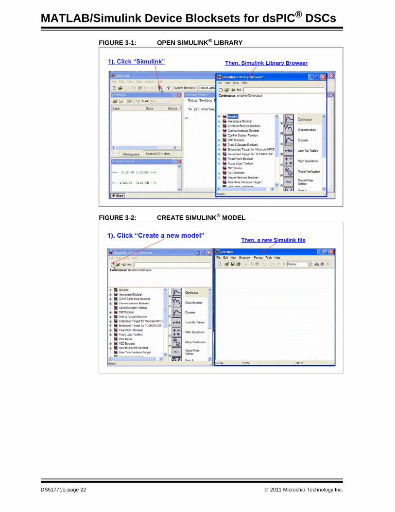
3. Click on 'New model' in Simulink Library Browser to create a new Simulink model file (Figure 3-2).
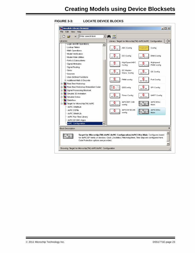
4. Locate Microchip device blocks from the Simulink library tree (Figure 3-3). Each model should contain one, and only one, "dsPIC33fxx_Main" block.
2011 Microchip Technology Inc. DS51771E-page 21
MATLAB/Simulink Device Blocksets for dsPIC® DSCs
FIGURE 3-1: OPEN SIMULINK® LIBRARY
FIGURE 3-2: CREATE SIMULINK® MODEL
DS51771E-page 22 2011 Microchip Technology Inc.
Creating Models using Device Blocksets
FIGURE 3-3: LOCATE DEVICE BLOCKS
2011 Microchip Technology Inc. DS51771E-page 23
MATLAB/Simulink Device Blocksets for dsPIC® DSCs
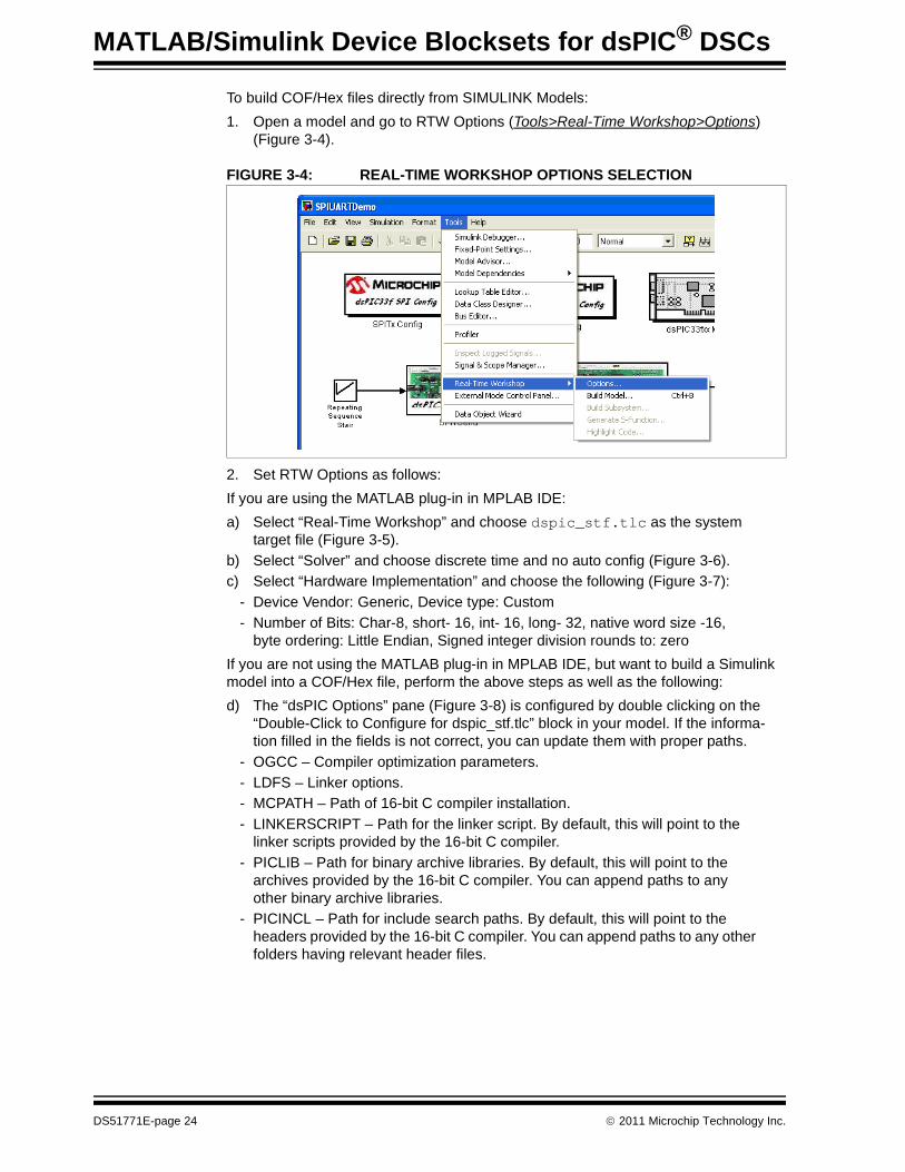
To build COF/Hex files directly from SIMULINK Models:
1. Open a model and go to RTW Options (Tools>Real-Time Workshop>Options) (Figure 3-4).
FIGURE 3-4: REAL-TIME WORKSHOP OPTIONS SELECTION
2. Set RTW Options as follows:
If you are using the MATLAB plug-in in MPLAB IDE:
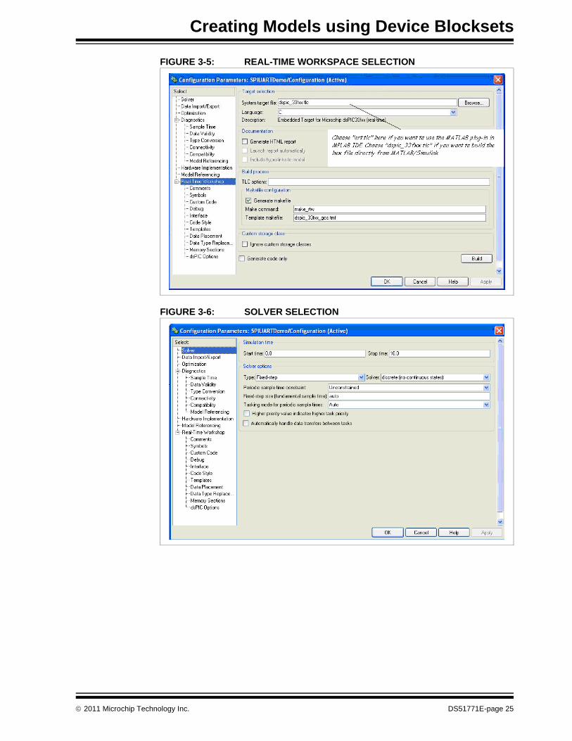
a) Select “Real-Time Workshop” and choose dspic_stf.tlc as the system target file (Figure 3-5).
b) Select “Solver” and choose discrete time and no auto config (Figure 3-6).
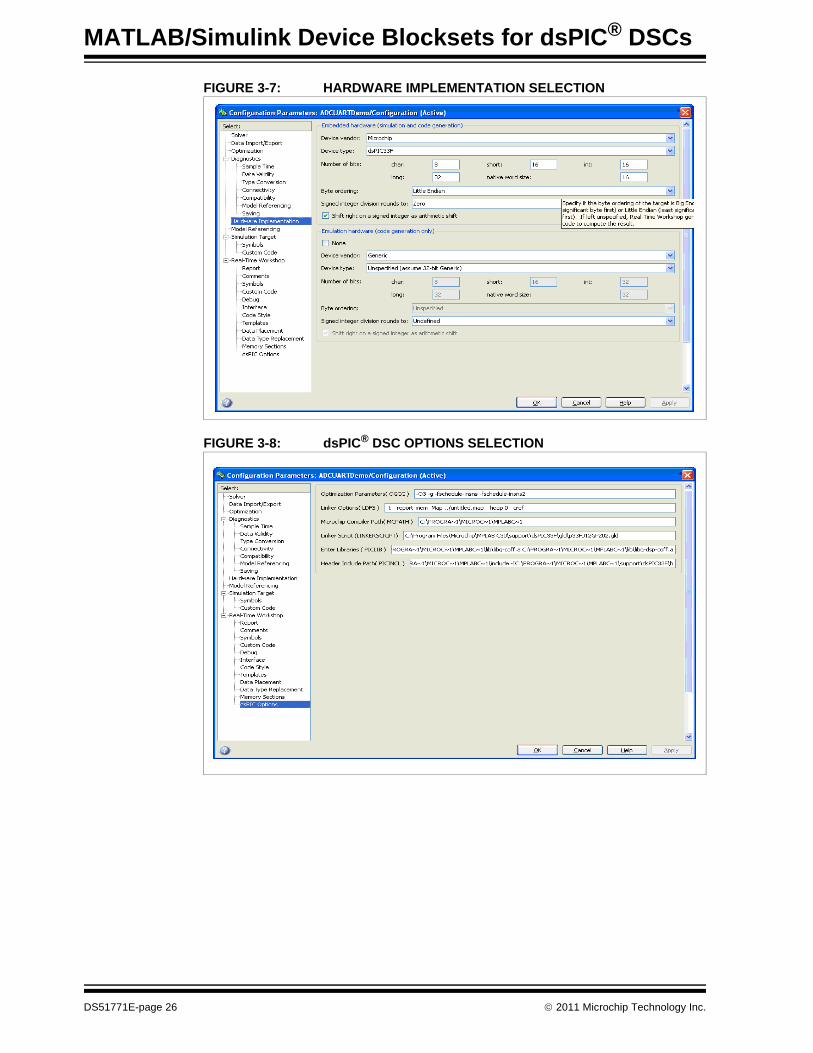
c) Select “Hardware Implementation” and choose the following (Figure 3-7):
- Device Vendor: Generic, Device type: Custom
- Number of Bits: Char-8, short- 16, int- 16, long- 32, native word size -16, byte ordering: Little Endian, Signed integer division rounds to: zero
If you are not using the MATLAB plug-in in MPLAB IDE, but want to build a Simulink model into a COF/Hex file, perform the above steps as well as the following:
d) The “dsPIC Options” pane (Figure 3-8) is configured by double clicking on the “Double-Click to Configure for dspic_stf.tlc” block in your model. If the informa-tion filled in the fields is not correct, you can update them with proper paths.
- OGCC – Compiler optimization parameters.
- LDFS – Linker options.
- MCPATH – Path of 16-bit C compiler installation.
- LINKERSCRIPT – Path for the linker script. By default, this will point to the linker scripts provided by the 16-bit C compiler.
- PICLIB – Path for binary archive libraries. By default, this will point to the archives provided by the 16-bit C compiler. You can append paths to any other binary archive libraries.
- PICINCL – Path for include search paths. By default, this will point to the headers provided by the 16-bit C compiler. You can append paths to any other folders having relevant header files.
DS51771E-page 24 2011 Microchip Technology Inc.
Creating Models using Device Blocksets
FIGURE 3-5: REAL-TIME WORKSPACE SELECTION
FIGURE 3-6: SOLVER SELECTION
2011 Microchip Technology Inc. DS51771E-page 25
MATLAB/Simulink Device Blocksets for dsPIC® DSCs
FIGURE 3-7: HARDWARE IMPLEMENTATION SELECTION
FIGURE 3-8: dsPIC® DSC OPTIONS SELECTION
DS51771E-page 26 2011 Microchip Technology Inc.

Creating Models using Device Blocksets
3. Build the model as follows:
To build from MATLAB, select Tools>Real-Time Workshop>Build Model (Figure 3-9.)
FIGURE 3-9: MATLAB® BUILD
To build from MPLAB IDE, refer to the MATLAB/Simulink plug-in documentation in MPLAB IDE. Make sure that a 16-bit C compiler is installed and its location correctly set in MPLAB IDE. 16-bit C compiler version 3.10 is recommended.
Note: Use only fixed point blocks available in Simulink. Floating point blocks may not always give correct results.
2011 Microchip Technology Inc. DS51771E-page 27
MATLAB/Simulink Device Blocksets for dsPIC® DSCs
NOTES:
DS51771E-page 28 2011 Microchip Technology Inc.
MATLAB/SIMULINK DEVICE®
BLOCKSETS FOR dsPIC DSCsChapter 4. Device Blocks FAQs
The following frequently asked questions may help you with some basic issues.
Can I use the plug-in in MPLAB IDE without having Microchip device blocksets?
Yes, the plug-in can be used even if you don't have Microchip device blocksets. In that case, you will need to use ert.tlc as the system target file. The code generated will adhere to ANSI C standards, and it may contain some calls to fflush kinds of func-tions, which may not compile with the 16-bit C compilers. Therefore, you may need to make some modifications to the code generated from your models.
The MATLAB plug-in tool can be selected with every device. Does it only support the dsPIC DSC devices currently? Can this be made device-specific?
The MATLAB plug-in in MPLAB IDE will take any MATLAB/Simulink model, generate code from it using the Real-Time Workshop (a MATLAB tool) and import the code gen-erated into the project you specify. Since the RTW generates ANSI C code, the plug-in will work with all devices, provided you have the right compiler in place. Currently there are only beta release blocksets for the dsPIC DSC family of devices. However, the device blockset is not mandatory to use the plug-in; the plug-in can be used with any Simulink model.
How efficient is the code Generated from MATLAB?
MATLAB provides two code generation tools: Real-Time Workshop (RTW) and Real-Time Embedded Coder (RTEC). RTEC generates code that is optimized for embedded platforms. The Microchip Device blocks work on RTEC and hence the code generated for generic blocks will be reasonably efficient. However, it will not be as effi-cient as manually-generated code because this code is not specifically targeted for Microchip targets.
A future Microchip Math Library with commonly used blocks is planned, for which spe-cialized drivers will be provided to generate efficient code. The device blocksets, how-ever, have Microchip’s drivers behind them and hence generate efficient code.
Error encountered while using 'PostCodeGenCommand', Error using => RTW.makertw.PCGHook
You are encountering this error because you either did not include the file MplabGetBuildInfo.m in the MATLAB include search path, or you have an older version of the file.
Is the device configuration block ‘Main’ required in any model?
Yes. Either “dsPIC33fxx main” or “dsPIC30fxx main” is a mandatory block for any given model that intends to use dspic_stf.tlc. This block is responsible for device configuration including clock, timer and watchdog settings.
Can I use two Device Config ‘Main’ blocks in a single model?
No. This would generate an error. It will cause the system to generate two main functions in a single project.
2011 Microchip Technology Inc. DS51771E-page 29
MATLAB/Simulink Device Blocksets for dsPIC® DSCs
Can I simulate models with device blocksets?
The device blocksets do not support simulations. However, their presence will not affect the simulation of models with blocks from DMC algorithms Library, Q15 Math Library, Floating point C math Libraries support simulation.
What are the priorities that I need to assign to blocks in a model?
The blocksets would inherit some default priority from the blockset libraries. You may change them if you want. But, the priority structure must fit into following rule:
Priority of device config block > Priority of peripheral config blocks > Priority of run-time blocks.
In MATLAB, the lower the number is, the higher the priority.
How can I make a certain part of the logic execute upon interrupts?
While configuring the peripheral that needs to generate interrupts, check the Enable interrupt option in its configuration block and assign the required priority.
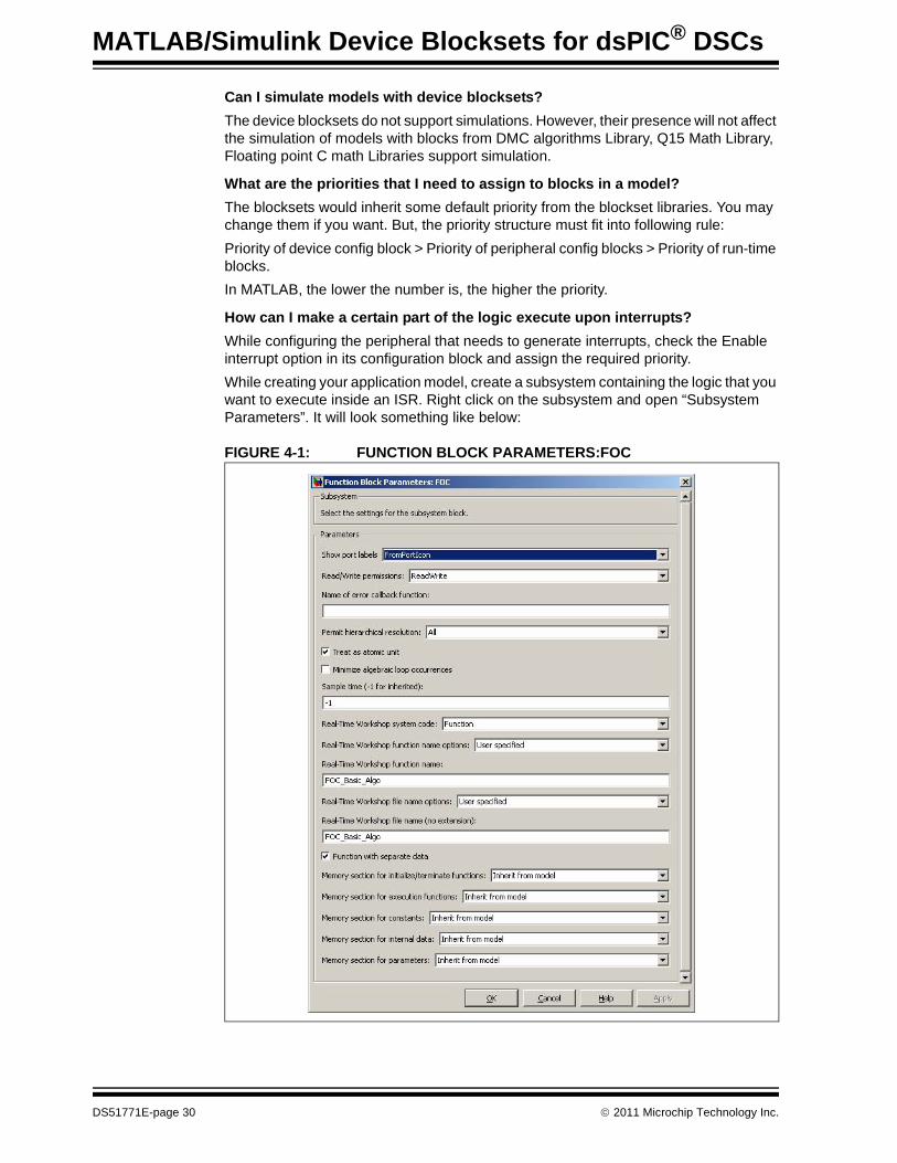
While creating your application model, create a subsystem containing the logic that you want to execute inside an ISR. Right click on the subsystem and open “Subsystem Parameters”. It will look something like below:
FIGURE 4-1: FUNCTION BLOCK PARAMETERS:FOC
DS51771E-page 30 2011 Microchip Technology Inc.
Make following settings:
a) Check “Treat as atomic unit”
b) Real-time workshop System code: Function
c) Real-time workshop function name options: User Specified
d) Real-time workshop function name: Specify a name of your choice
e) Check “function with separate data if required”
The code generated will have a separate function created for this subsystem. A call to that function would appear in the modelName.c file, which you can cut-and-paste inside the required ISR available in the Interrupts.c file.
You can refer to AN1078_FOC.mdl for an example.
When I try to build my model, I get errors. What should I be doing?
Look at the error pop-up and the command window for clues. If the error is from a make, possible reasons may be incompatible compiler version or required folders not being included in search paths. If you cannot diagnose the problem, go to support.microchip.com about the error encountered. You will need a zipped folder con-taining the model that generated the error and the generated code.
What are the limitations of the demo version of the blocksets? Where can I buy a license?
If you don't have a valid license, a 30 second delay will occur every time you build your model with Microchip blocksets.
To buy a license, you can either contact your local Microchip sales or you can buy it from www.microchipdirect.com.
2011 Microchip Technology Inc. DS51771E-page 31

MATLAB/Simulink Device Blocksets for dsPIC® DSCs
NOTES:
DS51771E-page 32 2011 Microchip Technology Inc.
MATLAB/SIMULINK DEVICE®
BLOCKSETS FOR dsPIC DSCsAppendix A. AN957 for dsPIC33F DSCs Example
This chapter is an addendum to the document and the code obtained from:
• http://ww1.microchip.com/downloads/en/AppNotes/AN957_33F_710.zip
This addendum discusses the use of the MATLAB v2007b demo model BLDC_Control_Demo.mdl with the application note AN957 for dsPIC33F DSCs.
A.1 HARDWARE SETUP
Refer to the AN957_33F README.doc obtained from the above zip file.
A.2 MODEL FUNCTIONALITY BRIEF DESCRIPTION
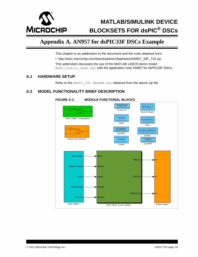
FIGURE A-1: MODULE FUNCTIONAL BLOCKS
2011 Microchip Technology Inc. DS51771E-page 33
MATLAB/Simulink Device Blocksets for dsPIC® DSCs
The ‘Input System’ provides the inputs from the microcontroller to the algorithm. The ‘BLDC Motor Control System’ is the main motor control algorithm. The ‘Output System’ drives the outputs on the microcontroller. ‘Reset Power Module’ does the generation of a pulse on the desired pin on the microcontroller. The different memory blocks, such as ‘PoleCount’ and ‘DirSwitch’, provide the run-time data retention. ‘dsPIC33fMC Config-uration’ configures the peripherals of the dsPIC33FJXXXMC710 microcontroller. The configurations are different compared to the code provided with AN957. This is to cater to the different execution of the code. The main differences are:
1. Timer1 is set up for loop execution.
2. Input Capture ports are not used.
3. Interrupt executions are not used.
4. Higher execution rate.
A.3 SOFTWARE FUNCTIONALITY
The following switches are used for software functionality:
1. S4: Pressing this switch starts and stops the motor.
2. S5: This switch toggles between open loop and closed loop control. By default, the motor starts running in open loop.
3. S6: This is used for direction switching. Although direction switching can be done while the motor is running, this is not advisable. Ideally, you should press S4 to stop the motor, then press S6 to change direction, after which you can press S4 to start the motor again.
4. R6 changes the speed of the motor, as specified in the application note (AN957).
A.4 SOFTWARE DEVIATIONS
The code in this example deviates from the original code in AN957 as follows:
1. The code provided in the ZIP file is interrupt driven. The interrupts are used for changing the energizing sequence of the motor windings. This interrupt method is not used in the MATLAB generated code. A fast polling mode is used to enable the complete code generation in a single loop of execution.
2. The original code runs at 10 MHz. Code generated by MATLAB runs at 40 MHz.
A.5 OPTIMIZATIONS
AN957 operation and the MATLAB model may be optimized as follows:
1. The functionality generated from MATLAB replicates the one available in AN957. AN957 is a PI control of the motor, which can be improved to provide the PID control.
2. Algorithm implementation of AN957 is for demonstration purposes. Therefore it contains truncations of the values, which can be improved to provide better con-trol and stability of the motor operations. The same applies for the MATLAB generated code.
3. The MATLAB generated code is not highly optimized. The code generated, though not bloated, can be further compressed in code size by using better model components/custom components for the algorithmic part.
DS51771E-page 34 2011 Microchip Technology Inc.
MATLAB/SIMULINK DEVICE®
BLOCKSETS FOR dsPIC DSCsIndex
Numerics16-bit C Compiler ..................................................... 27
AAbsolute Value....................................................16, 18ADC Config .............................................................. 11ADC Read................................................................ 13Addition .................................................................... 16AN957 ...................................................................... 33Arccosine ............................................................16, 18Arcsine ................................................................16, 18Arctangent...........................................................16, 18
CCAN Config .............................................................. 11CAN Receive/Transmit............................................. 13Clarke Transform ..................................................... 15COFF ..................................................................21, 24ComplexFFT32 ........................................................ 19ComplexIFFT32 ....................................................... 19Configuration Blocks ................................................ 11
ADC Config....................................................... 11CAN Config....................................................... 11DCI Config ........................................................ 12DMA Config ...................................................... 12dsPIC30fxx/33fxx Main ..................................... 11I2C Config ......................................................... 12IPCTimerCapture Config .................................. 12OC Config ......................................................... 12Port Config ........................................................ 13PWM Config...................................................... 12QEI Config ........................................................ 12SPI Config......................................................... 12Timer Config ..................................................... 13UART Config................................................12, 13
Cosine.................................................................16, 18
DDCI Config ............................................................... 12DCI Read/Write ........................................................ 13Deploying Device Blocksets....................................... 5Device Blocks
FAQ .................................................................. 29DMA Config.............................................................. 12DMC Algorithms....................................................... 15
Clarke Transform .............................................. 15InvClarkeTransform .......................................... 15InvParkTransform ............................................. 15Park Transform ................................................. 15PI Control .......................................................... 15Slide Motor Control ........................................... 15Space Vector Generation ................................. 15
DSP Library.............................................................. 19ComplexFFT32 ................................................. 19ComplexIFFT32 ................................................ 19FIR .................................................................... 19RealFFT32 ........................................................ 19RealIFFT32 ....................................................... 19Squared Magnitude........................................... 19
dsPIC Configuration Blocks ....................................... 6dsPIC Configuration Blocks, Setup .......................... 11dsPIC Runtime Library ............................................... 7dsPIC Runtime Library, Setup.................................. 13dspic_stf.tlc ........................................................ 21, 24dsPIC30fxx/33fxx Main ............................................ 11
EExponential ........................................................ 16, 18
FFFT........................................................................... 19FIR ........................................................................... 19Float to Integer ......................................................... 16Floating Point C Math Library................................... 18
Absolute Value.................................................. 18Arccosine .......................................................... 18Arcsine .............................................................. 18Arctangent......................................................... 18Cosine............................................................... 18Exponential ....................................................... 18Logarithm .......................................................... 18Modulo .............................................................. 18Raise to Power.................................................. 18Round ............................................................... 18Sine................................................................... 19Square Root...................................................... 19Tangent............................................................. 19
GGenerating Code...................................................... 21
HHex........................................................................... 24
II2C Config ................................................................ 12I2C Master/Slave...................................................... 13Installation .................................................................. 9IPCTimerCapture Config.......................................... 12
LLCD Display, dsPIC33F DSCs................................. 13Licensing .................................................................. 10Logarithm ........................................................... 17, 18Logarithm, Natural.................................................... 17
2011 Microchip Technology Inc. DS51771E-page 35
MATLAB/Simulink Device Blocksets for dsPIC® DSCs
MMath Library ....................................................... 16, 18Memory/Register Read/Write ................................... 14Models, Creating ...................................................... 21Modulo ..................................................................... 18Motor Control Algorithms.......................................... 15MPLAB IDE plug-in ............................................ 21, 24
NNOP Block................................................................ 14
OOC Config ................................................................ 12Output Compare....................................................... 12
PPark Transform......................................................... 15PI Control ................................................................. 15Port Config ............................................................... 13Port Read/Write........................................................ 14PostCodeGenCommand .......................................... 29Power ................................................................. 17, 18Prerequisites for Install............................................... 9PWM Config ............................................................. 12PWM Runtime Config............................................... 14
QQ15 Math Library ..................................................... 16
Absolute Value.................................................. 16Addition ............................................................. 16Arccosine .......................................................... 16Arcsine .............................................................. 16Arctangent......................................................... 16Cosine............................................................... 16Exponential ....................................................... 16Float to Integer .................................................. 16Logarithm .......................................................... 17Natural Logarithm ............................................. 17Raise to Power.................................................. 17Random Number............................................... 17Shift Left ............................................................ 17Shift Right ......................................................... 17Sine................................................................... 17Square Root ...................................................... 17Subtraction........................................................ 17Tangent ............................................................. 17
QEI Config................................................................ 12
RRandom Number...................................................... 17Real Time Workshop Options .................................. 24RealFFT32 ............................................................... 19RealIFFT32 .............................................................. 19Round....................................................................... 18RTW.makertw.PCGHook ......................................... 29Run-Time Library...................................................... 13
ADC Read......................................................... 13CAN Receive/Transmit...................................... 13DCI Read/Write ................................................. 13I2C Master/Slave .............................................. 13LCD Display, dsPIC33F DSCs.......................... 13
Memory/Register Read/Write............................ 14NOP Block......................................................... 14Port Read/Write................................................. 14PWM Runtime Config........................................ 14SPI Transmit/Receive ....................................... 14UART Transmit/Receive ................................... 14
SSFR .......................................................................... 14Shift Left ................................................................... 17Shift Right................................................................. 17Sine .................................................................... 17, 19Slide Motor Control................................................... 15Space Vector Generation ......................................... 15SPI Config ................................................................ 12SPI Transmit/Receive............................................... 14Square Root ....................................................... 17, 19Squared Magnitude .................................................. 19Subtraction ............................................................... 17
TTangent .............................................................. 17, 19Target for Microchip dsPIC DSC ................................ 5Timer Config............................................................. 13
UUART Config ............................................................ 13UART Transmit/Receive........................................... 14
DS51771E-page 36 2011 Microchip Technology Inc.

Index
NOTES:
2011 Microchip Technology Inc. DS51771E-page 37
DS51771E-page 38 2011 Microchip Technology Inc.
AMERICASCorporate Office2355 West Chandler Blvd.Chandler, AZ 85224-6199Tel: 480-792-7200 Fax: 480-792-7277Technical Support: http://www.microchip.com/supportWeb Address: www.microchip.com
AtlantaDuluth, GA Tel: 678-957-9614 Fax: 678-957-1455
BostonWestborough, MA Tel: 774-760-0087 Fax: 774-760-0088
ChicagoItasca, IL Tel: 630-285-0071 Fax: 630-285-0075
ClevelandIndependence, OH Tel: 216-447-0464 Fax: 216-447-0643
DallasAddison, TX Tel: 972-818-7423 Fax: 972-818-2924
DetroitFarmington Hills, MI Tel: 248-538-2250Fax: 248-538-2260
IndianapolisNoblesville, IN Tel: 317-773-8323Fax: 317-773-5453
Los AngelesMission Viejo, CA Tel: 949-462-9523 Fax: 949-462-9608
Santa ClaraSanta Clara, CA Tel: 408-961-6444Fax: 408-961-6445
TorontoMississauga, Ontario, CanadaTel: 905-673-0699 Fax: 905-673-6509
ASIA/PACIFICAsia Pacific OfficeSuites 3707-14, 37th FloorTower 6, The GatewayHarbour City, KowloonHong KongTel: 852-2401-1200Fax: 852-2401-3431
Australia - SydneyTel: 61-2-9868-6733Fax: 61-2-9868-6755
China - BeijingTel: 86-10-8528-2100 Fax: 86-10-8528-2104
China - ChengduTel: 86-28-8665-5511Fax: 86-28-8665-7889
China - ChongqingTel: 86-23-8980-9588Fax: 86-23-8980-9500
China - Hong Kong SARTel: 852-2401-1200 Fax: 852-2401-3431
China - NanjingTel: 86-25-8473-2460Fax: 86-25-8473-2470
China - QingdaoTel: 86-532-8502-7355Fax: 86-532-8502-7205
China - ShanghaiTel: 86-21-5407-5533 Fax: 86-21-5407-5066
China - ShenyangTel: 86-24-2334-2829Fax: 86-24-2334-2393
China - ShenzhenTel: 86-755-8203-2660 Fax: 86-755-8203-1760
China - WuhanTel: 86-27-5980-5300Fax: 86-27-5980-5118
China - XianTel: 86-29-8833-7252Fax: 86-29-8833-7256
China - XiamenTel: 86-592-2388138 Fax: 86-592-2388130
China - ZhuhaiTel: 86-756-3210040 Fax: 86-756-3210049
ASIA/PACIFICIndia - BangaloreTel: 91-80-3090-4444 Fax: 91-80-3090-4123
India - New DelhiTel: 91-11-4160-8631Fax: 91-11-4160-8632
India - PuneTel: 91-20-2566-1512Fax: 91-20-2566-1513
Japan - YokohamaTel: 81-45-471- 6166 Fax: 81-45-471-6122
Korea - DaeguTel: 82-53-744-4301Fax: 82-53-744-4302
Korea - SeoulTel: 82-2-554-7200Fax: 82-2-558-5932 or 82-2-558-5934
Malaysia - Kuala LumpurTel: 60-3-6201-9857Fax: 60-3-6201-9859
Malaysia - PenangTel: 60-4-227-8870Fax: 60-4-227-4068
Philippines - ManilaTel: 63-2-634-9065Fax: 63-2-634-9069
SingaporeTel: 65-6334-8870Fax: 65-6334-8850
Taiwan - Hsin ChuTel: 886-3-6578-300Fax: 886-3-6578-370
Taiwan - KaohsiungTel: 886-7-213-7830Fax: 886-7-330-9305
Taiwan - TaipeiTel: 886-2-2500-6610 Fax: 886-2-2508-0102
Thailand - BangkokTel: 66-2-694-1351Fax: 66-2-694-1350
EUROPEAustria - WelsTel: 43-7242-2244-39Fax: 43-7242-2244-393Denmark - CopenhagenTel: 45-4450-2828 Fax: 45-4485-2829
France - ParisTel: 33-1-69-53-63-20 Fax: 33-1-69-30-90-79
Germany - MunichTel: 49-89-627-144-0 Fax: 49-89-627-144-44
Italy - Milan Tel: 39-0331-742611 Fax: 39-0331-466781
Netherlands - DrunenTel: 31-416-690399 Fax: 31-416-690340
Spain - MadridTel: 34-91-708-08-90Fax: 34-91-708-08-91
UK - WokinghamTel: 44-118-921-5869Fax: 44-118-921-5820
Worldwide Sales and Service
02/18/11