maxon sensor - stork drivesstorkdrives.com/wp-content/uploads/2014/09/maxon-se… · ·...
TRANSCRIPT
377
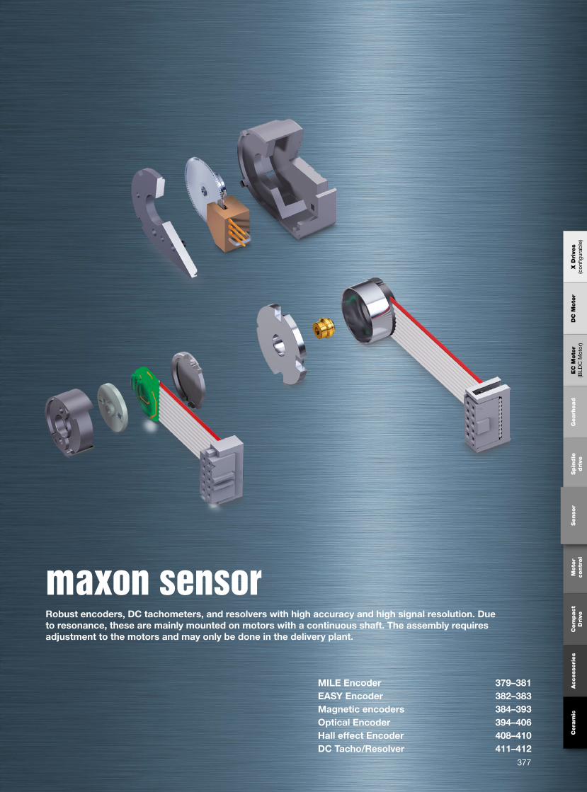
maxon sensor Robust encoders, DC tachometers, and resolvers with high accuracy and high signal resolution. Due to resonance, these are mainly mounted on motors with a continuous shaft. The assembly requires adjustment to the motors and may only be done in the delivery plant.
MILE Encoder 379–381EASY Encoder 382–383Magnetic encoders 384–393Optical Encoder 394–406Hall effect Encoder 408–410DC Tacho/Resolver 411–412
X D
rive
s(c
onfig
urab
le)
DC
Moto
r E
C M
oto
r(B
LDC
Mot
or)
Gearh
ead
Spin
dle
dri
veSenso
r M
oto
r
contr
ol
Com
pact
Dri
veA
ccess
ori
es
Cera
mic

max
on
mo
tor
378
maxon Standard Specification
With our Standard Specification we offer you a means to judge maxon motors in the most important respects. To our knowledge it covers normal applications. The Standard Specifica-tion is part of our “General Conditions of Sale”.
For information on standards and directives, refer to page 14 and 15.
The Standard Specification No. 100 for maxon DC motor1. Principles The standard specification describes tests
carried out on the finished motor and during the production process. In order to guar-antee our high quality standard, we check materials, parts and subassemblies through the manufacturing process and the complete motor. The obtained measurements are recorded and can be made available to cus-tomers if required. Random sampling plans are according to ISO 2859, MIL STD 105E and DIN/ISO 3951 (inspection by attributes, sequential sampling, variables inspection) as well as internal manufacturing controls. This specification always applies unless a different one has been agreed between the customer and maxon.
2. Data2.1 Electrical data apply at 22° to 25°C. Data
control within one minute running time. Measurement voltage +/- 0.5 % for voltages ≥ 3V and
± 0.015 V for voltages ≤ 3V
No load speed ± 10% No load current ≤ maximum specified
value Direction of rotation cw = clockwise Motor position horizontal Notes: Measurement voltage may vary from
the nominal voltage listed in the catalog. The no load current specified in the catalog is a typical value and not the maximum one. By connecting the red wires or if voltage is ap-plied to the ‘+’ Terminal, shaft rotation is cw (clockwise) as seen from the mounting end. For ccw running, the specified tolerance data may only be marginally exceeded.
Terminal resistance: Winding resistance is verified in the manufacturing process through spot checks on a representative basis. Terminal resistance is determined at product certification. It should be noted that terminal resistance depends on the rotor’s rotational position. As transfer resistance depends on current density in graphite brushes, measur-ing resistance with an ohmmeter if the current is low does not give reasonable results. Too low a reading is produced with precious metal brush motors if the brushes bridge two com-mutator segments, thereby short-circuiting one coil segment.
Inductance is determined at product certifi-cation. Test frequency is 1 kHz. The motor’s terminal inductance depends on frequency.
Commutation: An oscilloscope is used to check the neutral setting and test for electri-cal faults, such as interrupted winding or short-circuit between turns. Commutation displays for precious metal brushes and graphite brushes are not directly comparable. Precious metal brushes display a clear com-mutation picture which remains interfer-ence free up to the motor’s recommended maximum speed, but with graphite brushes, this is only expected up to around one third of that. In addition, it should be noted that the contact resistance of graphite brushes and the torque constant may change during the run-in period due to increased brush seating. As a result, no load current and speed may drift marginally. The same effect may also be observed if motors are being operated under no load condition over a longer period.
2.2 Mechanical data per outline drawing: Standardmeasuring instruments (for electrical length measuring DIN 32876, micrometer per DIN 863, dial indicator DIN 878, calliper per
DIN 862, bore calliper DIN 2245, thread cal-liper per DIN 2280 and others) are used.
2.3 Rotor imbalance: Rotors are balanced ac-cording to standard data or customer require-ments during manufacturing.
2.4 Noise: Tests are carried out for anomalies within a lot, on a subjective basis. Depending on speed, the motions in the motor cause noise and vibration of varying degrees, frequency and intensity. The noise level experienced with a single sample unit should not be interpreted as indicative of the noise or vibration level to be expected of future deliveries.
2.5 Service life: Durability tests are carried out under uniform internal criteria as part of product certification. A motor’s service life essentially depends on the operating and ambient conditions. Consequently, the many possible variations do not allow us to make a general statement on service life.
2.6 Environmental influences Protection against corrosion: Our products
are tested during product certification on the basis of DIN EN 60068-2-30.
Coating of components: Surface treatment and coating procedures used by maxon are selected on the basis of their merits to resist corrosion. These treatments are evaluated at product certification according to their ap-plicable standard.
3. Parameters that differ from or are additional to the data sheet can be specified and will be then a central part of our systematic testing as the customer’s specification. Test/inspection certificates are issued by prior agreement.
January 2010 edition / subject to change

max
on
sens
or
379
379
462002 462003 462004 462005
256 512 1024 20482 2 2 2
500 500 500 50010 000 10 000 10 000 10 000
EC 45 flat, 30 W 299 19.4 19.4 19.4 19.4EC 45 flat, 30 W 299 GP 42, 3 - 15 Nm 351 • • • •EC 45 flat, 30 W 299 GS 45, 0.5 - 2.0 Nm 353 • • • •EC 45 flat, 50 W 300 22.6 22.6 22.6 22.6EC 45 flat, 50 W 300 GP 42, 3 - 15 Nm 351 • • • •EC 45 flat, 50 W 300 GS 45, 0.5 - 2.0 Nm 353 • • • •EC 45 flat, 70 W 301 28.4 28.4 28.4 28.4EC 45 flat, 70 W 301 GP 42, 3 - 15 Nm 351 • • • •EC 45 flat, 70 W 301 GS 45, 0.5 - 2.0 Nm 353 • • • •
M 1:3s∆ 45°e<
s2 s = 90°e1..4s1s4s3
90°e
R
C
R
C
April 2016 edition / subject to change maxon sensor
Stock programStandard programSpecial program (on request)
overall length overall length
Encoder MILE 256–2048 CPT, 2 Channels, with Line DriverIntegrated into motor
maxon Modular System+ Motor Page + Gearhead Page + Brake Page Overall length [mm] / • see Gearhead
Article Numbers
TypeCounts per turnNumber of channelsMax. operating frequency (kHz)Max. speed (rpm)
Direction of rotation cw (definition cw p. 150)
Technical Data Pin Allocation Connection exampleSupply voltage VCC 5 V ± 10%Output signal CMOS and TTL compatibleState length sn 90°e (1000 rpm) 45…135°eSignal rise time (typically, at CL = 25 pF, RL = 1 kW, 25 °C) 100 nsSignal fall time (typically, at CL = 25 pF, RL = 1 kW, 25 °C) 100 nsOperating temperature range -40…+100 °CMoment of inertia of code wheel ≤ 3.5 gcm2
Output current per channel max. 4 mAOpen collector output of the Hall sensors with integrated pull-up resistor 10 kΩ ± 20%Wiring diagram for Hall sensors see p. 37
Additional information can be found Opt. terminal resistance R = typical 120 Wunder ‘Downloads’ in the maxon online shop. Capacitor C ≥ 0.1 nF per m line length
Connection motorPin 1 Hall sensor 1*Pin 2 Hall sensor 2*Pin 3 VHall 4.5...18 VDCPin 4 Motor winding 3Pin 5 Hall sensor 3*Pin 6 GNDPin 7 Motor winding 1Pin 8 Motor winding 2
*Internal pull-up (10 kW) on pin 3 (VHall)
Connection EncoderPin 1 N.C.Pin 2 VCC
Pin 3 GNDPin 4 N.C.Pin 5 Channel APin 6 Channel APin 7 Channel BPin 8 Channel BPin 9 Do not connectPin 10 Do not connect
Connector: 39-28-1083 Molex DIN 41651/EN 60603-13
Note: Pull-down resistors < 100 kΩ on the encoder outputs are not permitted. Pull-up resistors are permitted, but not required.
Line receiverRecommended IC's:- MC 3486- SN 75175- AM 26 LS 32
Channel B
Channel B
Channel A
Channel A
GND
VCC
Enc
oder
, Lin
e D
river
Channel A
Channel B
Cycle C = 360°e
Pulse P = 180°e
Phase shift
max
on
sens
or
380
380
EC 60 flat, IP00 304 39.0 39.0 39.0 39.0EC 60 flat, IP00 304 GP 52, 4 - 30 Nm 355 • • • •EC 60 flat, IP54 304 43.0 43.0 43.0 43.0EC 60 flat, IP54 304 GP 52, 4 - 30 Nm 355 • • • •
1
9
2
10300 ±10
s∆ 45°e<s2 s = 90°e1..4s1s4s3
90°e
R
C
R
C
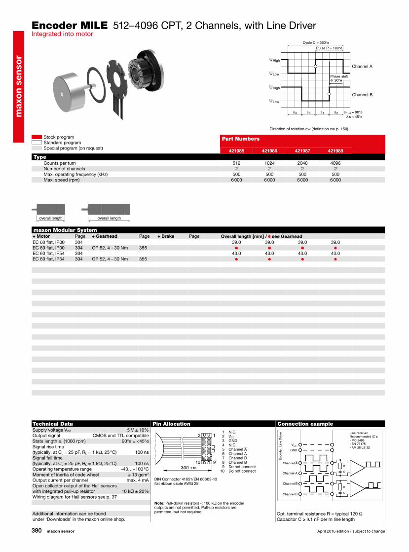
421985 421986 421987 421988
512 1024 2048 40962 2 2 2
500 500 500 5006 000 6 000 6 000 6 000
maxon sensor April 2016 edition / subject to change
Stock programStandard programSpecial program (on request)
overall length overall length
Encoder MILE 512–4096 CPT, 2 Channels, with Line DriverIntegrated into motor
maxon Modular System+ Motor Page + Gearhead Page + Brake Page Overall length [mm] / • see Gearhead
Part Numbers
TypeCounts per turnNumber of channelsMax. operating frequency (kHz)Max. speed (rpm)
Direction of rotation cw (definition cw p. 150)
Technical Data Pin Allocation Connection exampleSupply voltage VCC 5 V ± 10%Output signal CMOS and TTL compatibleState length sn (1000 rpm) 90°e ± <45°eSignal rise time (typically, at CL = 25 pF, RL = 1 kW, 25 °C) 100 nsSignal fall time (typically, at CL = 25 pF, RL = 1 kW, 25 °C) 100 nsOperating temperature range -40…+100 °CMoment of inertia of code wheel ≤ 13 gcm2
Output current per channel max. 4 mAOpen collector output of the Hall sensors with integrated pull-up resistor 10 kΩ ± 20%Wiring diagram for Hall sensors see p. 37
Additional information can be found Opt. terminal resistance R = typical 120 Wunder ‘Downloads’ in the maxon online shop. Capacitor C ≥ 0.1 nF per m line length
DIN Connector 41651/EN 60603-13flat ribbon cable AWG 28
1 N.C. 2 VCC
3 GND 4 N.C. 5 Channel A 6 Channel A 7 Channel B 8 Channel B 9 Do not connect10 Do not connect
Note: Pull-down resistors < 100 kΩ on the encoder outputs are not permitted. Pull-up resistors are permitted, but not required.
Line receiverRecommended IC's:- MC 3486- SN 75175- AM 26 LS 32
Channel B
Channel B
Channel A
Channel A
GND
VCC
Enc
oder
, Lin
e D
river
Channel A
Channel B
Cycle C = 360°e
Pulse P = 180°e
Phase shift
max
on
sens
or
381
381
EC 90 flat 305 29.2 29.2 29.2 29.2 29.2 29.2 29.2 29.2EC 90 flat 305 GP 52, 4 - 30 Nm 355 • • • • • • • •
M 1:3s∆ 45°e<
s2 s = 90°e1..4s1s4s3
90°e
R
R
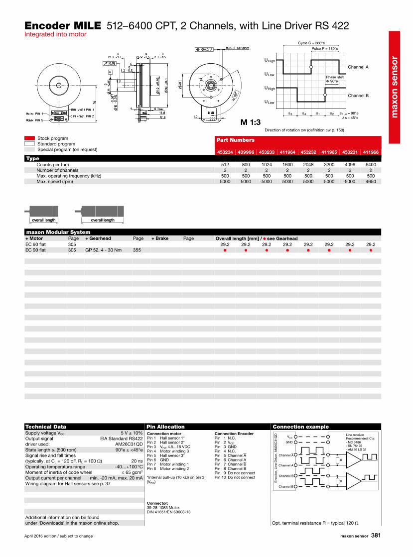
453234 409996 453233 411964 453232 411965 453231 411966
512 800 1024 1600 2048 3200 4096 64002 2 2 2 2 2 2 2
500 500 500 500 500 500 500 5005000 5000 5000 5000 5000 5000 5000 4650
April 2016 edition / subject to change maxon sensor
Stock programStandard programSpecial program (on request)
overall length overall length
Encoder MILE 512–6400 CPT, 2 Channels, with Line Driver RS 422Integrated into motor
maxon Modular System+ Motor Page + Gearhead Page + Brake Page Overall length [mm] / • see Gearhead
Technical Data Pin Allocation Connection exampleSupply voltage VCC 5 V ± 10%Output signal EIA Standard RS422 driver used: AM26C31QDState length sn (500 rpm) 90°e ± <45°eSignal rise and fall times (typically, at CL = 120 pF, RL = 100 Ω) 20 nsOperating temperature range -40…+100 °CMoment of inertia of code wheel ≤ 65 gcm2
Output current per channel min. -20 mA, max. 20 mAWiring diagram for Hall sensors see p. 37
Additional information can be foundunder ‘Downloads’ in the maxon online shop. Opt. terminal resistance R = typical 120 Ω
Connection motorPin 1 Hall sensor 1*Pin 2 Hall sensor 2*Pin 3 VHall 4.5...18 VDCPin 4 Motor winding 3Pin 5 Hall sensor 3*Pin 6 GNDPin 7 Motor winding 1Pin 8 Motor winding 2
*Internal pull-up (10 kW) on pin 3 (VHall)
Part Numbers
TypeCounts per turnNumber of channelsMax. operating frequency (kHz)Max. speed (rpm)
Direction of rotation cw (definition cw p. 150)
Connection EncoderPin 1 N.C.Pin 2 VCC
Pin 3 GNDPin 4 N.C.Pin 5 Channel APin 6 Channel APin 7 Channel BPin 8 Channel BPin 9 Do not connectPin 10 Do not connect
Connector: 39-28-1083 Molex DIN 41651/EN 60603-13
Line receiverRecommended IC's:- MC 3486- SN 75175- AM 26 LS 32
Channel B
Channel B
Channel A
Channel A
GND
VCC
Enc
oder
, Lin
e D
river
, AM
26C
31Q
D
Channel A
Channel B
Cycle C = 360°e
Pulse P = 180°e
Phase shift
overall length overall length

max
on
sens
or
382
EC-i 40, 50 W 281/282 37.7 37.7 37.7 37.7 37.7 37.7EC-i 40, 50 W 281 GP 32, 1 - 6 Nm 343 • • • • • •EC-i 40, 50 W 281 GP 32 S 370-372 • • • • • •EC-i 40, 50 W 281/282 GP 42, 3 - 15 Nm 350 • • • • • •EC-i 40, 70 W 283/284 47.7 47.7 47.7 47.7 47.7 47.7EC-i 40, 70 W 283 GP 32, 1 - 6 Nm 343 • • • • • •EC-i 40, 70 W 283 GP 32 S 370-372 • • • • • •EC-i 40, 70 W 283/284 GP 42, 3 - 15 Nm 350 • • • • • •EC-i 40, 100 W 285 67.7 67.7 67.7 67.7 67.7 67.7EC-i 40, 100 W 285 GP 42, 3 - 15 Nm 350 • • • • • •EC-i 52, 180 W 286 93.7 93.7 93.7 93.7 93.7 93.7EC-i 52, 180 W 286 GP 52, 4 - 30 Nm 354 • • • • • •
1
9
2
10300 ±10
s∆ 45°e<s2 s = 90°e1..4s1s4s3
U
U
U
U
U
U
High
High
High
Low
Low
Low
90°e
R
R
R
499356 499357 499358 499359 499360 499361
128 256 500 512 1000 10243 3 3 3 3 3
200 400 800 800 1600 160030 000 30 000 30 000 30 000 30 000 30 00090 ± 45 90 ± 45 90 ± 60 90 ± 45 90 ± 80 90 ± 7090 ± 45 90 ± 45 90 ± 60 90 ± 45 90 ± 80 90 ± 70
maxon sensor April 2016 edition / subject to change
Stock programStandard programSpecial program (on request)
Encoder 16 EASY 128–1024 CPT, 3 Channels, with Line Driver RS 422
maxon Modular System+ Motor Page + Gearhead Page + Brake Page Overall length [mm] / • see Gearhead
Part Numbers
Type (provisional)Counts per turnNumber of channelsMax. operating frequency (kHz)Max. speed (rpm)Phase shift Φ (°e)Index pulse width (°e)
Technical Data Pin Allocation Connection exampleSupply voltage VCC 5 V ± 10%Output signal EIA Standard RS 422Operating temperature range -40…+100 °CMoment of inertia of code wheel ≤ 0.09 gcm2
Output current per channel ± 20 mAHysteresis 0.17 °mMin. state duration s 125 nsSignal rise and fall times(typically, at CL = 200 pF, RL = 100 Ω) 20 ns
The angle value 0 is matched to the commutation phase of winding 1 (in acc. with Hall 1 signal on motors withHall sensors, block commutation), see p. 34.
Additional information can be found in the maxononline shop under downloads.The index signal I is synchronized with channel A or B. Opt. terminal resistance R = typical 120 Ω
1 N.C. 2 VCC
3 GND 4 N.C. 5 Channel A 6 Channel A 7 Channel B 8 Channel B 9 Channel I (Index)10 Channel I (Index)
DIN Connector 41651/EN 60603-13flat band cable AWG 28
Direction of rotation cw (definition cw p. 150)
Line receiverRecommended IC's:- MC 3486- SN 75175- AM 26 LS 32
Channel B
Channel B
Channel A
Channel A
Channel I
Channel I
GND
VCC
Enc
oder
, Lin
e D
river
overall length overall length
Channel A
Channel B
Channel I
Cycle C = 360°e
Pulse P = 180°e
Phase shift

max
on
sens
or
383
EC-i 40, 50 W 281/282 37.7 37.7EC-i 40, 50 W 281/282 EPOS2 50/5 425 Signal Cable J5 300586 • •EC-i 40, 50 W 281/282 EPOS2 70/10 425 Signal Cable J5B 378173 • •EC-i 40, 50 W 281/282 MAXPOS 50/5 435 Sensor Cable X6 451290 • •EC-i 40, 70 W 283/284 47.7 47.7EC-i 40, 70 W 283/284 EPOS2 50/5 425 Signal Cable J5 300586 • •EC-i 40, 70 W 283/284 EPOS2 70/10 425 Signal Cable J5B 378173 • •EC-i 40, 70 W 283/284 MAXPOS 50/5 435 Sensor Cable X6 451290 • •EC-i 40, 100 W 285 67.7 67.7EC-i 40, 100 W 285 EPOS2 50/5 425 Signal Cable J5 300586 • •EC-i 40, 100 W 285 EPOS2 70/10 425 Signal Cable J5B 378173 • •EC-i 40, 100 W 285 MAXPOS 50/5 435 Sensor Cable X6 451290 • •EC-i 52, 180 W 286 93.7 93.7EC-i 52, 180 W 286 EPOS2 70/10 425 Signal Cable J5B 378173 • •EC-i 52, 180 W 286 MAXPOS 50/5 435 Sensor Cable X6 451290 • •
488783 488782
4096 409612 12
BiSS-C SSI30 000 30 000
Gray Symmetric0.6 0.0410 42 16
1
9
2
10300 ±10
D
R
GND
VCC
CLK+
CLK-
Data+
Data-
Data
Clock
GND
VCC VCC
GND
VCC
GND
D11 D10 nE
MSB
D0
TimeoutLSB
Tclock
Data Range
CDSStartAck nW CRC5
CRC0
CRC..
CDM
D11 D10 D0D1
MSB
D2
Clock
DataLSB
Tclock
0
TimeoutData Range
Clock
Data
SSI
BiSS-C
April 2016 edition / subject to change maxon sensor
Stock programStandard programSpecial program (on request)
1 Data 2 VCC
3 GND 4 CLK 5 Do not connect (A) 6 Do not connect (A) 7 Do not connect (B) 8 Do not connect (B) 9 Do not connect (I)10 Do not connect (I)
DIN Connector 41651/EN 60603-13flat ribbon cable AWG 28
overall length overall length
Encoder 16 EASY Absolute 4096 steps, Single Turn
maxon modular system+ Motor Page + Electronics Page + Accessories* Total length [mm]
* + Adapter EASY Absolute 488167 (required for all maxon controllers)
Part numbers
Type (provisional)Steps per turnResolution (bit single turn)Signal protocolMax. mech. speed (rpm)Data encoding BinaryMin. clock frequency CLK (MHz)Max. clock frequency CLK (MHz)Timeout (ms)
Technical data Pin assignment Connection exampleSupply voltage VCC 5 V ± 10%Output signal CMOS compatibleOutput current, data max. 20 mACurrent draw, typ. (no load) 17 mASetup time after Power On max. 4 msHysteresis 0.17° mechMoment of inertia of code wheel ≤ 0.09 gcm2
Operating temperature range -40…+100 °C
The angle value 0 is matched to the commutation phase of winding 1 (in acc. with Hall 1 signal on motors withHall sensors, block commutation), see p. 34.
Additional information can be foundunder 'Downloads' in the maxon online shop.
Angle values increase when direction of rotation is cw (definition of 'cw' on p. 150)
Enc
oder
Posi
tioni
ng c
ontr
olle
r
Adapter EASY Absolute 488167

max
on
sens
or
384
EC 6, 1.5 W 236 23.4 23.4 23.4EC 6, 1.5 W 236 GP 6, 0.002 - 0.03 Nm 311 • • •EC 6, 1.5 W 236 GP 6 S 361-362 • • •EC 6, 2.0 W 237 23.4 23.4 23.4EC 6, 2.0 W 237 GP 6, 0.002 - 0.03 Nm 311 • • •EC 6, 2.0 W 237 GP 6 S 361-362 • • •
502804 502805 502806
64 128 2563 3 364 64 64
100 000 50 000 25 000
s∆ 45°e<s2 s = 90°e1..4s1s4s3
U
U
U
U
U
U
High
High
High
Low
Low
Low
90°e
maxon sensor April 2016 edition / subject to change
Stock programStandard programSpecial program (on request)
Encoder 6–8 MAG 64–256 CPT, 3 Channels
maxon Modular System+ Motor Page + Gearhead Page + Brake Page Overall length [mm] / • see Gearhead
Part Numbers
Type (provisional)Counts per turnNumber of channelsMax. operating frequency (kHz)Max. speed (rpm)
Direction of rotation cw (definition cw p. 150)
Technical Data Pin Allocation Connection exampleSupply voltage VCC 3 - 3.6 VOutput signal VCC = 3.3 VDC TTL compatiblePhase shift Φ 90°e ± 45°eIndex pulse width 90°e ± 45°eOperating temperature range -40…+125 °CMoment of inertia of code wheel ≤ 0.001 gcm2
Output current per channel ≤ 4 mA
Channel A
Channel B
Channel I
Cycle C = 360°e
Pulse P = 180°e
Phase shift
overall length overall length
No Pull-upnecessarily
Encoder DC EC 1 Motor + W1 2 Motor – W2 3 NC W3 4 GND GND 5 VCC VCC
6 Channel A Channel A 7 Channel B Channel B 8 Channel I Channel I 9 NC H110 NC H211 NC H312 NC NC
Compatible connector: Molex 52745-0697, Tyco 1-1734839-4Adapter: 498157

max
on
sens
or
385
RE 10, 0.75 W 155 22.8RE 10, 0.75 W 155 GP 10, 0.005 - 0.15 Nm 313/314 •RE 10, 1.5 W 157 30.4RE 10, 1.5 W 157 GP 10, 0.005 - 0.15 Nm 313/314 •RE 13, 0.75 W 160 26.3RE 13, 0.75 W 161 28.7RE 13, 0.75 W 161 GP 13, 0.05 - 0.15 Nm 316 •RE 13, 0.75 W 161 GP 13, 0.2 - 0.35 Nm 317 •RE 13, 2 W 164 38.5RE 13, 2 W 165 40.9RE 13, 2 W 165 GP 13, 0.05 - 0.15 Nm 316 •RE 13, 2 W 165 GP 13, 0.2 - 0.35 Nm 317 •RE 13, 1.5 W 168 28.4RE 13, 1.5 W 169 30.8RE 13, 1.5 W 169 GP 13, 0.05 - 0.15 Nm 316 •RE 13, 1.5 W 169 GP 13, 0.2 - 0.35 Nm 317 •RE 13, 3 W 172 40.6RE 13, 3 W 173 43.0RE 13, 3 W 173 GP 13, 0.05 - 0.15 Nm 316 •RE 13, 3 W 173 GP 13, 0.2 - 0.35 Nm 317 •A-max 12, 0.5 W 192 25.3A-max 12, 0.5 W 192 GP 10, 0.01 - 0.15 Nm 314 •A-max 12, 0.5 W 192 GS 12, 0.01 - 0.03 Nm 315 •A-max 12, 0.5 W 192 GP 13, 0.05 - 0.15 Nm 316 •A-max 12, 0.5 W 192 GP 13, 0.2 - 0.35 Nm 317 •RE-max 13, 0.75 W 220 25.2RE-max 13, 0.75 W 220 GP 13, 0.05 - 0.15 Nm 316 •RE-max 13, 0.75 W 220 GP 13, 0.2 - 0.35 Nm 317 •RE-max 13, 2 W 222 36.2RE-max 13, 2 W 222 GP 13, 0.05 - 0.15 Nm 316 •RE-max 13, 2 W 222 GP 13, 0.2 - 0.35 Nm 317 •
1
9
2
10156 ±10
201933 224702
16 162 28 8
30 000 30 000
s∆ 45°e<s2 s = 90°e1..4s1s4s3
90°e
April 2016 edition / subject to change maxon sensor
Stock programStandard programSpecial program (on request)
overall length overall length
Encoder MR Type S, 16 CPT, 2 Channels
maxon Modular System+ Motor Page + Gearhead Page + Brake Page Overall length [mm] / • see Gearhead
Technical Data Pin Allocation Connection exampleSupply voltage VCC 2.7 - 5.5 VOutput signal VCC = 5 VDC TTL compatiblePhase shift Φ 90°e ± 45°eOperating temperature range -25…+85 °CMoment of inertia of code wheel ≤ 0.005 gcm2
Output current per channel max. 5 mA
Part Numbers
TypeCounts per turnNumber of channelsMax. operating frequency (kHz)Max. speed (rpm)
1 Motor +2 VCC
3 Channel A4 Channel B5 GND6 Motor – DIN Connector 41651/EN 60603-13flat band cable AWG 28
Direction of rotation cw (definition cw p. 150)
Encoder
No Pull-upnecessarily
Channel A
Channel B
Cycle C = 360°e
Pulse P = 180°e
Phase shift

max
on
sens
or
386
RE 8, 0.5 W, A 153 22.6RE 8, 0.5 W, A 153 GP 8, 0.01 - 0.1 Nm 312 •RE 8, 0.5 W, A 153 GP 8 S 363–364 •RE 10, 0.75 W 155 22.8 22.8 22.8RE 10, 0.75 W 155 GP 10, 0.005 - 0.15 Nm 313/314 • • •RE 10, 1.5 W 157 30.4 30.4 30.4RE 10, 1.5 W 157 GP 10, 0.005 - 0.15 Nm 313/314 • • •RE 13, 0.75 W 160 26.3 26.3 26.3RE 13, 0.75 W 161 28.7 28.7 28.7RE 13, 0.75 W 161 GP 13, 0.05 - 0.15 Nm 316 • • •RE 13, 0.75 W 161 GP 13, 0.2 - 0.35 Nm 317 • • •RE 13, 2 W 164 38.5 38.5 38.5RE 13, 2 W 165 40.9 40.9 40.9RE 13, 2 W 165 GP 13, 0.05 - 0.15 Nm 316 • • •RE 13, 2 W 165 GP 13, 0.2 - 0.35 Nm 317 • • •RE 13, 1.5 W 168 28.4 28.4 28.4RE 13, 1.5 W 169 30.8 30.8 30.8RE 13, 1.5 W 169 GP 13, 0.05 - 0.15 Nm 316 • • •RE 13, 1.5 W 169 GP 13, 0.2 - 0.35 Nm 317 • • •RE 13, 3 W 172 40.6 40.6 40.6RE 13, 3 W 173 43.0 43.0 43.0RE 13, 3 W 173 GP 13, 0.05 - 0.15 Nm 316 • • •RE 13, 3 W 173 GP 13, 0.2 - 0.35 Nm 317 • • •A-max 12, 0.5 W 192 25.3 25.3 25.3A-max 12, 0.5 W 192 GP 10, 0.01 - 0.15 Nm 314 • • •A-max 12, 0.5 W 192 GS 12, 0.01 - 0.03 Nm 315 • • •A-max 12, 0.5 W 192 GP 13, 0.05 - 0.15 Nm 316 • • •A-max 12, 0.5 W 192 GP 13, 0.2 - 0.35 Nm 317 • • •RE-max 13, 0.75 W 220 25.2 25.2 25.2RE-max 13, 0.75 W 220 GP 13, 0.05 - 0.15 Nm 316 • • •RE-max 13, 0.75 W 220 GP 13, 0.2 - 0.35 Nm 317 • • •RE-max 13, 2 W 222 36.2 36.2 36.2RE-max 13, 2 W 222 GP 13, 0.05 - 0.15 Nm 316 • • •RE-max 13, 2 W 222 GP 13, 0.2 - 0.35 Nm 317 • • •
323049 323050 334910 323051 323052 323053 323054
64 64 100 128 128 256 2562 2 2 2 2 2 2
80 80 100 160 160 320 32075 000 75 000 60 000 75 000 75 000 75 000 75 000
s∆ 45°e<s2 s = 90°e1..4s1s4s3
90°e
R
C
R
C
maxon sensor April 2016 edition / subject to change
Stock programStandard programSpecial program (on request)
overall length overall length
Encoder MR Type S, 64–256 CPT, 2 Channels, with Line Driver
maxon Modular System+ Motor Page + Gearhead Page + Brake Page Overall length [mm] / • see Gearhead
Technical Data Pin Allocation Connection exampleSupply voltage VCC 5 V ± 5%Output signal TTL compatiblePhase shift Φ 90°e ± 45°eOperating temperature range -25…+85 °CMoment of inertia of code wheel ≤ 0.005 gcm2
Output current per channel max. 5 mA
Terminal resistance R = typical 120 WCapacitor C ≥ 0.1 nF per m line length
Part Numbers
TypeCounts per turnNumber of channelsMax. operating frequency (kHz)Max. speed (rpm)
Direction of rotation cw (definition cw p. 150)
1 Motor + 2 VCC
3 GND 4 Motor – 5 Channel A 6 Channel A 7 Channel B 8 Channel B 9 N.C.10 N.C.
1 Motor + 2 VCC
3 GND 4 Motor – 5 Channel A 6 Channel A 7 Channel B 8 Channel B
Part Numbers 323049 – 323054Pin 1 – 10 / X = 0.3 ±0.05 / Y = 11 −0.1 / L = 80 ±3Compatible connector: Molex 52207-1033, Tyco 1-84953-0 Pitch 1.0 mm, top contact style
Part Numbers 334910Pin 1 – 8 / X = 0.3 ±0.03 / Y = 4.5 ±0.07 / L = 84 ±3Compatible connector: Molex 52745-0833
Line receiverRecommended IC's:- MC 3486- SN 75175- AM 26 LS 32
Channel B
Channel B
Channel A
Channel A
GND
VCC
Enc
oder
, Lin
e D
river
Channel A
Channel B
Cycle C = 360°e
Pulse P = 180°e
Phase shift

max
on
sens
or
387
RE 13, 0.75 W 160 26.3 26.3 26.3RE 13, 0.75 W 161 28.7 28.7 28.7RE 13, 0.75 W 161 GP 13, 0.05 - 0.15 Nm 316 • • •RE 13, 0.75 W 161 GP 13, 0.2 - 0.35 Nm 317 • • •RE 13, 2 W 164 38.5 38.5 38.5RE 13, 2 W 165 40.9 40.9 40.9RE 13, 2 W 165 GP 13, 0.05 - 0.15 Nm 316 • • •RE 13, 2 W 165 GP 13, 0.2 - 0.35 Nm 317 • • •RE 13, 1.5 W 168 28.4 28.4 28.4RE 13, 1.5 W 169 30.8 30.8 30.8RE 13, 1.5 W 169 GP 13, 0.05 - 0.15 Nm 316 • • •RE 13, 1.5 W 169 GP 13, 0.2 - 0.35 Nm 317 • • •RE 13, 3 W 172 40.6 40.6 40.6RE 13, 3 W 173 43.0 43.0 43.0RE 13, 3 W 173 GP 13, 0.05 - 0.15 Nm 316 • • •RE 13, 3 W 173 GP 13, 0.2 - 0.35 Nm 317 • • •RE-max 13, 0.75 W 220 25.2 25.2 25.2RE-max 13, 0.75 W 220 GP 13, 0.05 - 0.15 Nm 316 • • •RE-max 13, 0.75 W 220 GP 13, 0.2 - 0.35 Nm 317 • • •RE-max 13, 2 W 222 36.2 36.2 36.2RE-max 13, 2 W 222 GP 13, 0.05 - 0.15 Nm 316 • • •RE-max 13, 2 W 222 GP 13, 0.2 - 0.35 Nm 317 • • •
1
9
2
10156 ±10
241057 241060 241062
64 128 2562 2 280 160 320
75 000 75 000 75 000
s∆ 45°e<s2 s = 90°e1..4s1s4s3
90°e
April 2016 edition / subject to change maxon sensor
Stock programStandard programSpecial program (on request)
Encoder MR Type S, 64–256 CPT, 2 Channels
maxon Modular System+ Motor Page + Gearhead Page + Brake Page Overall length [mm] / • see Gearhead
Part Numbers
TypeCounts per turnNumber of channelsMax. operating frequency (kHz)Max. speed (rpm)
Direction of rotation cw (definition cw p. 150)
Technical Data Pin Allocation Connection exampleSupply voltage VCC 5 V ± 5%Output signal TTL compatiblePhase shift Φ 90°e ± 45°eOperating temperature range -25…+85 °CMoment of inertia of code wheel ≤ 0.005 gcm2
Output current per channel max. 5 mA
1 Motor +2 VCC
3 Channel A4 Channel B5 GND6 Motor –7 N.C.DIN Connector 41651/EN 60603-13flat band cable AWG 28
Encoder
No Pull-upnecessarily
Channel A
Channel B
Cycle C = 360°e
Pulse P = 180°e
Phase shift
overall length overall length
max
on
sens
or
388
RE 16, 2 W 174 28.0 28.0RE 16, 2 W 174 GP 16, 0.1 - 0.6 Nm 323/324 • •RE 16, 2 W 174 GP 16 S 365/366 • •RE 16, 3.2 W 176 45.4 45.4RE 16, 3.2 W 176 GP 16, 0.1 - 0.6 Nm 323/324 • •RE 16, 3.2 W 176 GP 16 S 365/366 • •RE 16, 4.5 W 178 48.4 48.4RE 16, 4.5 W 178 GP 16, 0.1 - 0.6 Nm 323/324 • •RE 16, 4.5 W 178 GP 16 S 365/366 • •A-max 16 194/196 30.4 30.4A-max 16 194/196 GS 16, 0.01 - 0.1 Nm 319-322 • •A-max 16 194/196 GP 16, 0.1 - 0.3 Nm 323 • •A-max 16 194/196 GP 16 S 365/366 • •A-max 19, 1.5 W 198 34.0 34.0A-max 19, 1.5 W 198 GP 19, 0.1 - 0.3 Nm 325 • •A-max 19, 1.5 W 198 GP 22, 0.5 - 2.0 Nm 331 • •A-max 19, 1.5 W 198 GS 24, 0.1 Nm 335 • •A-max 19, 1.5 W 198 GP 22 S 368/369 • •A-max 19, 2.5 W 200 35.8 35.8A-max 19, 2.5 W 200 GP 19, 0.1 - 0.3 Nm 325 • •A-max 19, 2.5 W 200 GS 20, 0.06 - 0.25 Nm 326 • •A-max 19, 2.5 W 200 GP 22, 0.5 - 2.0 Nm 331 • •A-max 19, 2.5 W 200 GS 24, 0.1 Nm 335 • •A-max 19, 2.5 W 200 GP 22 S 368/369 • •A-max 22 202/204 36.9 36.9A-max 22 202/204 GP 22, 0.1 - 0.6 Nm 327/328 • •A-max 22 202/204 GP 22, 0.5 - 2.0 Nm 327-331 • •A-max 22 202/204 GS 24, 0.1 Nm 335 • •A-max 22 202/204 GP 22 S 368/369 • •
1
9
2
10156 ±10
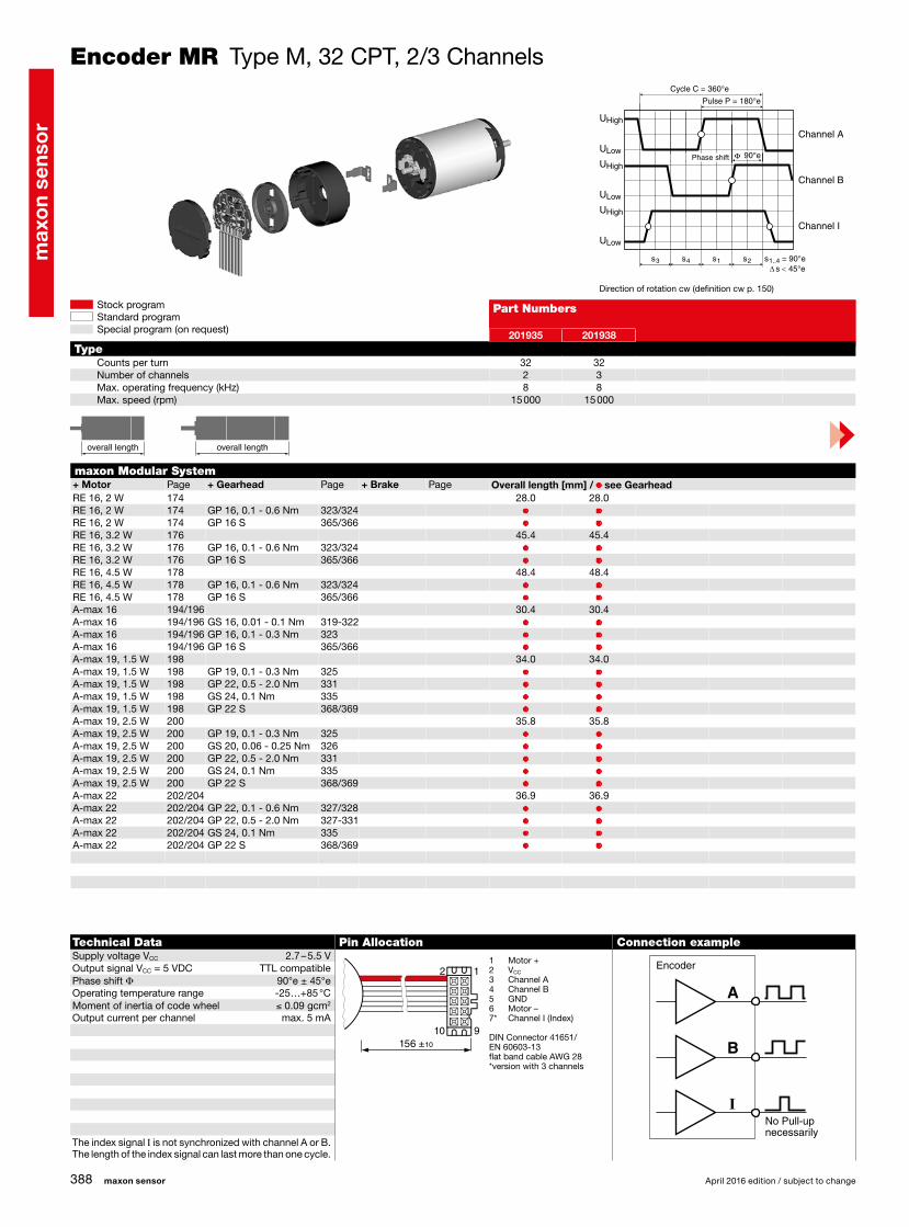
201935 201938
32 322 38 8
15 000 15 000
maxon sensor April 2016 edition / subject to change
Stock programStandard programSpecial program (on request)
Encoder MR Type M, 32 CPT, 2/3 Channels
maxon Modular System+ Motor Page + Gearhead Page + Brake Page Overall length [mm] / • see Gearhead
Part Numbers
TypeCounts per turnNumber of channelsMax. operating frequency (kHz)Max. speed (rpm)
Direction of rotation cw (definition cw p. 150)
Technical Data Pin Allocation Connection exampleSupply voltage VCC 2.7 – 5.5 VOutput signal VCC = 5 VDC TTL compatiblePhase shift Φ 90°e ± 45°eOperating temperature range -25…+85 °CMoment of inertia of code wheel ≤ 0.09 gcm2
Output current per channel max. 5 mA
The index signal I is not synchronized with channel A or B.The length of the index signal can last more than one cycle.
1 Motor +2 VCC
3 Channel A4 Channel B5 GND6 Motor –7* Channel I (Index)
DIN Connector 41651/EN 60603-13flat band cable AWG 28*version with 3 channels
No Pull-upnecessarily
Encoder
s
U
U
U
U
U
U
High
High
High
Low
Low
Low
∆ 45°e<s2 s = 90°e1..4s1s4s3
90°e
Channel A
Channel B
Channel I
Cycle C = 360°e
Pulse P = 180°e
Phase shift
overall length overall length

max
on
sens
or
389
RE-max 21, 3.5 W 224 34.0 34.0RE-max 21, 3.5 W 224 GP 22, 0.5 - 2.0 Nm 329/331 • •RE-max 21, 3.5 W 224 GS 38, 0.1 - 0.6 Nm 348 • •RE-max 21, 3.5 W 224 GP 22 S 368/369 • •RE-max 21, 6 W 226 35.8 35.8RE-max 21, 6 W 226 GP 22, 0.5 - 2.0 Nm 329/331 • •RE-max 21, 6 W 226 GS 38, 0.1 - 0.6 Nm 348 • •RE-max 21, 6 W 226 GP 22 S 368/369 • •
1
9
2
10156 ±10
201935 201938
32 322 38 8
15 000 15 000
April 2016 edition / subject to change maxon sensor
Stock programStandard programSpecial program (on request)
Encoder MR Type M, 32 CPT, 2/3 Channels
maxon Modular System+ Motor Page + Gearhead Page + Brake Page Overall length [mm] / • see Gearhead
Part Numbers
TypeCounts per turnNumber of channelsMax. operating frequency (kHz)Max. speed (rpm)
Direction of rotation cw (definition cw p. 150)
Technical Data Pin Allocation Connection exampleSupply voltage VCC 2.7 – 5.5 VOutput signal VCC = 5 VDC TTL compatiblePhase shift Φ 90°e ± 45°eOperating temperature range -25…+85 °CMoment of inertia of code wheel ≤ 0.09 gcm2
Output current per channel max. 5 mA
The index signal I is not synchronized with channel A or B.The length of the index signal can last more than one cycle.
1 Motor +2 VCC
3 Channel A4 Channel B5 GND6 Motor –7* Channel I (Index)
DIN Connector 41651/EN 60603-13flat band cable AWG 28*version with 3 channels
No Pull-upnecessarily
Encoder
s
U
U
U
U
U
U
High
High
High
Low
Low
Low
∆ 45°e<s2 s = 90°e1..4s1s4s3
90°e
Channel A
Channel B
Channel I
Cycle C = 360°e
Pulse P = 180°e
Phase shift
overall length overall length

max
on
sens
or
390
RE 16, 2 W 174 28.0 28.0 28.0 28.0 28.0 28.0RE 16, 2 W 174 GP 16, 0.1 - 0.6 Nm 323/324 • • • • • •RE 16, 2 W 174 GP 16 S 365/366 • • • • • •RE 16, 3.2 W 176 45.4 45.4 45.4 45.4 45.4 45.4RE 16, 3.2 W 176 GP 16, 0.1 - 0.6 Nm 323/324 • • • • • •RE 16, 3.2 W 176 GP 16 S 365/366 • • • • • •RE 16, 4.5 W 178 48.4 48.4 48.4 48.4 48.4 48.4RE 16, 4.5 W 178 GP 16, 0.1 - 0.6 Nm 323/324 • • • • • •RE 16, 4.5 W 178 GP 16 S 365/366 • • • • • •A-max 16 194/196 30.4 30.4 30.4 30.4 30.4 30.4A-max 16 194/196 GS 16, 0.01 - 0.1 Nm 319-322 • • • • • •A-max 16 194/196 GP 16, 0.1 - 0.6 Nm 323/324 • • • • • •A-max 16 194/196 GP 16 S 365/366 • • • • • •A-max 19, 1.5 W 198 34.0 34.0 34.0 34.0 34.0 34.0A-max 19, 1.5 W 198 GP 19, 0.1 - 0.3 Nm 325 • • • • • •A-max 19, 1.5 W 198 GP 22, 0.5 - 2.0 Nm 329/331 • • • • • •A-max 19, 1.5 W 198 GS 24, 0.1 Nm 335 • • • • • •A-max 19, 1.5 W 198 GP 22 S 368/369 • • • • • •A-max 19, 2.5 W 200 35.8 35.8 35.8 35.8 35.8 35.8A-max 19, 2.5 W 200 GP 19, 0.1 - 0.3 Nm 325 • • • • • •A-max 19, 2.5 W 200 GS 20 0.06 - 0.25 Nm 326 • • • • • •A-max 19, 2.5 W 200 GP 22, 0.5 - 2.0 Nm 329/331 • • • • • •A-max 19, 2.5 W 200 GS 24, 0.1 Nm 335 • • • • • •A-max 19, 2.5 W 200 GP 22 S 368/369 • • • • • •A-max 22 202/204 36.9 36.9 36.9 36.9 36.9 36.9A-max 22 202/204 GP 22, 0.1 - 0.6 Nm 327/328 • • • • • •A-max 22 202/204 GP 22, 0.5 - 2.0 Nm 329/331 • • • • • •A-max 22 202/204 GS 24, 0.1 Nm 335 • • • • • •A-max 22 202/204 GP 22 S 368/369 • • • • • •
1
9
2
10156 ±10
228179 228177 228181 228182 201937 201940
128 128 256 256 512 5122 3 2 3 2 380 80 160 160 320 320
37 500 37 500 37 500 37 500 37 500 37 500
R
R
R
maxon sensor April 2016 edition / subject to change
Stock programStandard programSpecial program (on request)
Encoder MR Type M, 128–512 CPT, 2/3 Channels, with Line Driver
maxon Modular System+ Motor Page + Gearhead Page + Brake Page Overall length [mm] / • see Gearhead
Part Numbers
TypeCounts per turnNumber of channelsMax. operating frequency (kHz)Max. speed (rpm)
Direction of rotation cw (definition cw p. 150)
Technical Data Pin Allocation Connection exampleSupply voltage VCC 5 V ± 5%Output signal TTL compatiblePhase shift Φ 90°e ± 45°eIndex pulse width 90°e ± 45°eOperating temperature range -25…+85 °CMoment of inertia of code wheel ≤ 0.09 gcm2
Output current per channel max. 5 mA
The index signal I is synchronized with channel A or B. Opt. terminal resistance R > 1 kΩ
1 Motor + 2 VCC
3 GND 4 Motor – 5 Channel A 6 Channel A 7 Channel B 8 Channel B 9* Channel I (Index)10* Channel I (Index)
DIN Connector 41651/EN 60603-13flat band cable AWG 28*version with 3 channels
s∆ 45°e<s2 s = 90°e1..4s1s4s3
U
U
U
U
U
U
High
High
High
Low
Low
Low
90°e
Channel A
Channel B
Channel I
Cycle C = 360°e
Pulse P = 180°e
Phase shift
overall length overall length
Line receiverRecommended IC's:- MC 3486- SN 75175- AM 26 LS 32
Channel B
Channel B
Channel A
Channel A
Channel I
Channel I
GND
VCC
Enc
oder
, Lin
e D
river

max
on
sens
or
391
RE-max 21, 3.5 W 224 34.0 34.0 34.0 34.0 34.0 34.0RE-max 21, 3.5 W 224 GP 22, 0.5 - 2.0 Nm 329/331 • • • • • •RE-max 21, 3.5 W 224 GS 38, 0.1 - 0.6 Nm 348 • • • • • •RE-max 21, 3.5 W 224 GP 22 S 368/369 • • • • • •RE-max 21, 6 W 226 35.8 35.8 35.8 35.8 35.8 35.8RE-max 21, 6 W 226 GP 22, 0.5 - 2.0 Nm 329/331 • • • • • •RE-max 21, 6 W 226 GS 38, 0.1 - 0.6 Nm 348 • • • • • •RE-max 21, 6 W 226 GP 22 S 368/369 • • • • • •EC 16, 30 W 244 50.7 50.7 50.7 50.7 50.7 50.7EC 16, 30 W 244 GP 16, 0.1 - 0.6 Nm 323/324 • • • • • •EC 16, 30 W 244 GP 22, 0.5 - 1.0 Nm 329 • • • • • •EC 16, 30 W 244 GP 16 S 365/366 • • • • • •EC 16, 60 W 245 66.7 66.7 66.7 66.7 66.7 66.7EC 16, 60 W 245 GP 16, 0.2 - 0.6 Nm 324 • • • • • •EC 16, 60 W 245 GP 22, 0.5 - 2.0 Nm 329/332 • • • • • •EC 16, 60 W 245 GP 16 S/GP 22 S 365/369 • • • • • •EC 22, 40 W 246 50.5 50.5 50.5 50.5 50.5 50.5EC 22, 40 W 246 GP 22, 0.5 - 3.4 Nm 332/333 • • • • • •EC 22, 40 W 246 GP 22 S 368/369 • • • • • •EC 22, 100 W 247 68.7 68.7 68.7 68.7 68.7 68.7EC 22, 100 W 247 GP 22, 0.5 - 3.4 Nm 332/333 • • • • • •EC 22, 100 W 247 GP 22 S 368/369 • • • • • •EC-max 16, 5 W 259 31.3 31.3 31.3 31.3 31.3 31.3EC-max 16, 5 W 259 GP 16, 0.1 - 0.6 Nm 323/324 • • • • • •EC-max 16, 5 W 259 GP 16 S 365/366 • • • • • •EC-max 16, 8 W 261 43.3 43.3 43.3 43.3 43.3 43.3EC-max 16, 8 W 261 GP 16, 0.2 - 0.6 Nm 324 • • • • • •EC-max 16, 8 W 261 GP 22, 0.5 - 2.0 Nm 332 • • • • • •EC-max 16, 8 W 261 GP 16 S/GP 22 S 365/369 • • • • • •EC-max 22, 12 W 262 41.7 41.7 41.7 41.7 41.7 41.7EC-max 22, 12 W 262 GP 22, 0.5 - 2.0 Nm 332/333 • • • • • •EC-max 22, 12 W 262 KD 32, 1.0 - 4.5 Nm 347 • • • • • •EC-max 22, 12 W 262 GP 22 S 368/369 • • • • • •EC-max 22, 25 W 263 58.2 58.2 58.2 58.2 58.2 58.2EC-max 22, 25 W 263 GP 22/GP 32 333/343 • • • • • •EC-max 22, 25 W 263 GP 32 S 370-372 • • • • • •
1
9
2
10156 ±10
1
9
2
10306 ±10
228179 228177 228181 228182 201937 201940
128 128 256 256 512 5122 3 2 3 2 380 80 160 160 320 320
37 500 37 500 37 500 37 500 37 500 37 500
R
R
R
April 2016 edition / subject to change maxon sensor
Stock programStandard programSpecial program (on request)
Encoder MR Type M, 128–512 CPT, 2/3 Channels, with Line Driver
maxon Modular System+ Motor Page + Gearhead Page + Brake Page Overall length [mm] / • see Gearhead
Part Numbers
TypeCounts per turnNumber of channelsMax. operating frequency (kHz)Max. speed (rpm)
Direction of rotation cw (definition cw p. 150)
Technical Data Pin Allocation Connection exampleSupply voltage VCC 5 V ± 5%
MR Encoder EC-max 16 / EC-max 22
Output signal TTL compatiblePhase shift Φ 90°e ± 45°eIndex pulse width 90°e ± 45°eOperating temperature range -25…+85 °CMoment of inertia of code wheel ≤ 0.09 gcm2
Output current per channel max. 5 mA
The index signal I is synchronized with channel A or B. Opt. terminal resistance R > 1 kΩ
1 N.C. 2 VCC
3 GND 4 N.C. 5 Channel A 6 Channel A 7 Channel B 8 Channel B 9* Channel I (Index)10* Channel I (Index)
DIN Connector 41651/EN 60603-13flat band cable AWG 28*version with 3 channels
Pin assignment for RE-max see Page 390
MR Encoder EC 16 / EC 22
s∆ 45°e<s2 s = 90°e1..4s1s4s3
U
U
U
U
U
U
High
High
High
Low
Low
Low
90°e
Channel A
Channel B
Channel I
Cycle C = 360°e
Pulse P = 180°e
Phase shift
Line receiverRecommended IC's:- MC 3486- SN 75175- AM 26 LS 32
Channel B
Channel B
Channel A
Channel A
Channel I
Channel I
GND
VCC
Enc
oder
, Lin
e D
river

max
on
sens
or
392
RE 25 179/181 65.5 65.5 65.5 65.5 65.5RE 25 179/181 GP 26, 0.75 - 2.0 Nm 336 • • • • •RE 25 179/181 GP 32, 0.75 - 6.0 Nm 338-343 • • • • •RE 25 179/181 KD 32, 1.0 - 4.5 Nm 347 • • • • •RE 25 179/181 GP 32 S 370-372 • • • • •RE 25, 20 W 180 54.0 54.0 54.0 54.0 54.0RE 25, 20 W 180 GP 22, 0.5 Nm 329 • • • • •RE 25, 20 W 180 GP 26, 0.75 - 2.0 Nm 336 • • • • •RE 25, 20 W 180 GP 32, 0.75 - 6.0 Nm 338-343 • • • • •RE 25, 20 W 180 KD 32, 1.0 - 4.5 Nm 347 • • • • •RE 25, 20 W 180 GP 32 S 370-372 • • • • •A-max 26 206-212 53.5 53.5 53.5 53.5 53.5A-max 26 206-212 GP 26, 0.75 - 4.5 Nm 336 • • • • •A-max 26 206-212 GS 30, 0.07 - 0.2 Nm 337 • • • • •A-max 26 206-212 GP 32, 0.75 - 6.0 Nm 338-343 • • • • •A-max 26 206-212 GS 38, 0.1 - 0.6 Nm 348 • • • • •A-max 26 206-212 GP 32 S 370-372 • • • • •RE-max 29 227-230 53.5 53.5 53.5 53.5 53.5RE-max 29 227-230 GP 32, 0.75 - 6.0 Nm 339-343 • • • • •RE-max 29 227-230 GP 32 S 370-372 • • • • •EC-max 30, 40 W 264 54.2 54.2EC-max 30, 40 W 264 GP 32, 1 - 8.0 Nm 343/345 • •EC-max 30, 40 W 264 KD 32, 1.0 - 4.5 Nm 347 • •EC-max 30, 40 W 264 GP 32 S 370-372 • •EC-max 30, 60 W 265 76.2 76.2EC-max 30, 60 W 265 GP 32, 1 - 8.0 Nm 343/345 • •EC-max 30, 60 W 265 KD 32, 1.0 - 4.5 Nm 347 • •EC-max 30, 60 W 265 GP 42, 3 - 15 Nm 350 • •EC-4pole 30 273 59.2 59.2EC-4pole 30 273 GP 32, 4.0 - 8.0 Nm 345 • •EC-4pole 30 273 GP 42, 3 - 15 Nm 350 • •EC-4pole 30 275 76.2 76.2EC-4pole 30 275 GP 32, 4.0 - 8.0 Nm 345 • •EC-4pole 30 275 GP 42, 3 - 15 Nm 350 • •
1
9
2
10506 ±10
225771 225773 225778 225805 225780
128 256 500 512 10003 3 3 3 380 160 200 320 200
37 500 37 500 24 000 37 500 12 000
R
R
R
maxon sensor April 2016 edition / subject to change
Stock programStandard programSpecial program (on request)
Encoder MR Type ML, 128–1000 CPT, 3 Channels, with Line Driver
maxon Modular System+ Motor Page + Gearhead Page + Brake Page Overall length [mm] / • see Gearhead
Part Numbers
TypeCounts per turnNumber of channelsMax. operating frequency (kHz)Max. speed (rpm)
Direction of rotation cw (definition cw p. 150)
Technical Data Pin Allocation Connection exampleSupply voltage VCC 5 V ± 5%Output signal TTL compatiblePhase shift Φ 90°e ± 45°eIndex pulse width 90°e ± 45°eOperating temperature range -25…+85 °CMoment of inertia of code wheel ≤ 0.7 gcm2
Output current per channel max. 5 mA
The index signal I is synchronized with channel A or B. Opt. terminal resistance R > 1 kΩ
1 N.C. 2 VCC
3 GND 4 N.C. 5 Channel A 6 Channel A 7 Channel B 8 Channel B 9 Channel I (Index)10 Channel I (Index)
DIN Connector 41651/EN 60603-13flat band cable AWG 28
s∆ 45°e<s2 s = 90°e1..4s1s4s3
U
U
U
U
U
U
High
High
High
Low
Low
Low
90°e
Channel A
Channel B
Channel I
Cycle C = 360°e
Pulse P = 180°e
Phase shift
overall length overall length
Line receiverRecommended IC's:- MC 3486- SN 75175- AM 26 LS 32
Channel B
Channel B
Channel A
Channel A
Channel I
Channel I
GND
VCC
Enc
oder
, Lin
e D
river

max
on
sens
or
393
RE 30, 15 W 182 79.4 79.4 79.4 79.4 79.4RE 30, 15 W 182 GP 32, 0.75 - 4.5 Nm 340 • • • • •RE 30, 60 W 183 79.4 79.4 79.4 79.4 79.4RE 30, 60 W 183 GP 32, 0.75 - 4.5 Nm 338 • • • • •RE 30, 60 W 183 GP 32, 0.75 - 6.0 Nm 340-344 • • • • •RE 30, 60 W 183 GP 32 S 370-372 • • • • •RE 35, 90 W 184 82.4 82.4 82.4 82.4 82.4RE 35, 90 W 184 GP 32, 0.75 - 4.5 Nm 338 • • • • •RE 35, 90 W 184 GP 32, 0.75 - 6.0 Nm 340-344 • • • • •RE 35, 90 W 184 GP 32, 4.0 - 8.0 Nm 345 • • • • •RE 35, 90 W 184 GP 42, 3 - 15 Nm 349 • • • • •RE 35, 90 W 184 GP 32 S 370-372 • • • • •RE 40, 25 W 185 82.4 82.4 82.4 82.4 82.4RE 40, 150 W 186 82.4 82.4 82.4 82.4 82.4RE 40, 150 W 186 GP 42, 3 - 15 Nm 349 • • • • •RE 40, 150 W 186 GP 52, 4 - 30 Nm 354 • • • • •A-max 32 214/216 72.7 72.7 72.7 72.7 72.7A-max 32 214/216 GP 32, 0.75 - 6.0 Nm 340-343 • • • • •A-max 32 214/216 GS 38, 0.1 - 0.6 Nm 348 • • • • •A-max 32 214/216 GP 32 S 370-372 • • • • •EC-max 40, 70 W 266 73.9 73.9 73.9 73.9 73.9EC-max 40, 70 W 266 GP 42, 3 - 15 Nm 350 • • • • •EC-max 40, 120 W 267 103.9 103.9 103.9 103.9 103.9EC-max 40, 120 W 267 GP 52, 4 - 30 Nm 355 • • • • •
1
9
2
10506 ±10
225783 228452 225785 228456 225787
256 500 512 1000 10243 3 3 3 380 200 160 200 320
18 750 24 000 18 750 12 000 18 750
R
R
R
April 2016 edition / subject to change maxon sensor
Stock programStandard programSpecial program (on request)
Encoder MR Type L, 256–1024 CPT, 3 Channels, with Line Driver
maxon Modular System+ Motor Page + Gearhead Page + Brake Page Overall length [mm] / • see Gearhead
Part Numbers
TypeCounts per turnNumber of channelsMax. operating frequency (kHz)Max. speed (rpm)
Direction of rotation cw (definition cw p. 150)
Technical Data Pin Allocation Connection exampleSupply voltage VCC 5 V ± 5%Output signal TTL compatiblePhase shift Φ 90°e ± 45°eIndex pulse width 90°e ± 45°eOperating temperature range -25…+85 °CMoment of inertia of code wheel ≤ 1.7 gcm2
Output current per channel max. 5 mA
The index signal I is synchronized with channel A or B. Opt. terminal resistance R > 1 kΩ
1 N.C. 2 VCC
3 GND 4 N.C. 5 Channel A 6 Channel A 7 Channel B 8 Channel B 9 Channel I (Index)10 Channel I (Index)
DIN Connector 41651/EN 60603-13flat band cable AWG 28
s∆ 45°e<s2 s = 90°e1..4s1s4s3
U
U
U
U
U
U
High
High
High
Low
Low
Low
90°e
Channel A
Channel B
Channel I
Cycle C = 360°e
Pulse P = 180°e
Phase shift
overall length overall length
Line receiverRecommended IC's:- MC 3486- SN 75175- AM 26 LS 32
Channel B
Channel B
Channel A
Channel A
Channel I
Channel I
GND
VCC
Enc
oder
, Lin
e D
river

max
on
sens
or
394
EC 6, 1.5 W 236 23.4EC 6, 1.5 W 236 GP 6, 0.002 - 0.03 Nm 311 •EC 6, 1.5 W 236 GP 6 S 361-362 •EC 6, 2.0 W 237 23.4EC 6, 2.0 W 237 GP 6, 0.002 - 0.03 Nm 311 •EC 6, 2.0 W 237 GP 6 S 361-362 •
502807
1283
6460 000
maxon sensor April 2016 edition / subject to change
Stock programStandard programSpecial program (on request)
maxon Modular System+ Motor Page + Gearhead Page + Brake Page Overall length [mm] / • see Gearhead
Part Numbers
Type (provisional)Counts per turnNumber of channelsMax. operating frequency (kHz)Max. speed (rpm)
overall length overall length
Technical Data Pin Allocation Connection exampleSupply voltage VCC 3 - 6 VPhase shift Φ 90°e ± 45°eIndex pulse width 90°e ± 45°eOperating temperature range -20…+85 °CMoment of inertia of code wheel ≤ 0.001 gcm2
Output current per channel ≤ 5 mA
No Pull-upnecessarily
Encoder DC EC 1 Motor + W1 2 Motor – W2 3 NC W3 4 GND GND 5 VCC VCC
6 Channel A Channel A 7 Channel B Channel B 8 Channel I Channel I 9 NC NC10 NC NC11 NC NC12 NC NC
Compatible connector: Molex 52745-0697, Tyco 1-1734839-4Adapter: 498157
Encoder 6–8 OPT 128 CPT, 3 Channels
Direction of rotation cw (definition cw p. 150)
s∆ 45°e<s2 s = 90°e1..4s1s4s3
U
U
U
U
U
U
High
High
High
Low
Low
Low
90°e
Channel A
Channel B
Channel I
Cycle C = 360°e
Pulse P = 180°e
Phase shift

max
on
sens
or
395
RE 8, 0.5 W, A 153 24.2RE 8, 0.5 W, A 153 GP 8, 0.01 - 0.1 Nm 312 •RE 8, 0.5 W, A 153 GP 8 S 363–364 •
473594
502
1518 000
s∆ 45°e<s2 s = 90°e1..4s1s4s3
90°e
April 2016 edition / subject to change maxon sensor
Stock programStandard programSpecial program (on request)
Encoder 8 OPT 50 CPT, 2 Channels
maxon Modular System+ Motor Page + Gearhead Page + Brake Page Overall length [mm] / • see Gearhead
Part Numbers
Type (provisional)Counts per turnNumber of channelsMax. operating frequency (kHz)Max. speed (rpm)
Direction of rotation cw (definition cw p. 150)
Technical Data Pin Allocation Connection exampleSupply voltage VCC 1) 3 V ± 10%Phase shift Φ 90°e ± 45°eOperating temperature range -20…+85 °CMoment of inertia of code wheel ≤ 0.001 gcm2
Output current per channel min. -1 mA, max. 8 mA
1) Not in combination with maxon controllers.
1 Motor +2 VCC
3 Channel A4 Channel B5 GND6 Motor –
Compatible connector: Molex 52745-0697
Encoder
No Pull-upnecessarily
Channel A
Channel B
Cycle C = 360°e
Pulse P = 180°e
Phase shift
overall length overall length
max
on
sens
or
396
9
2
10
1
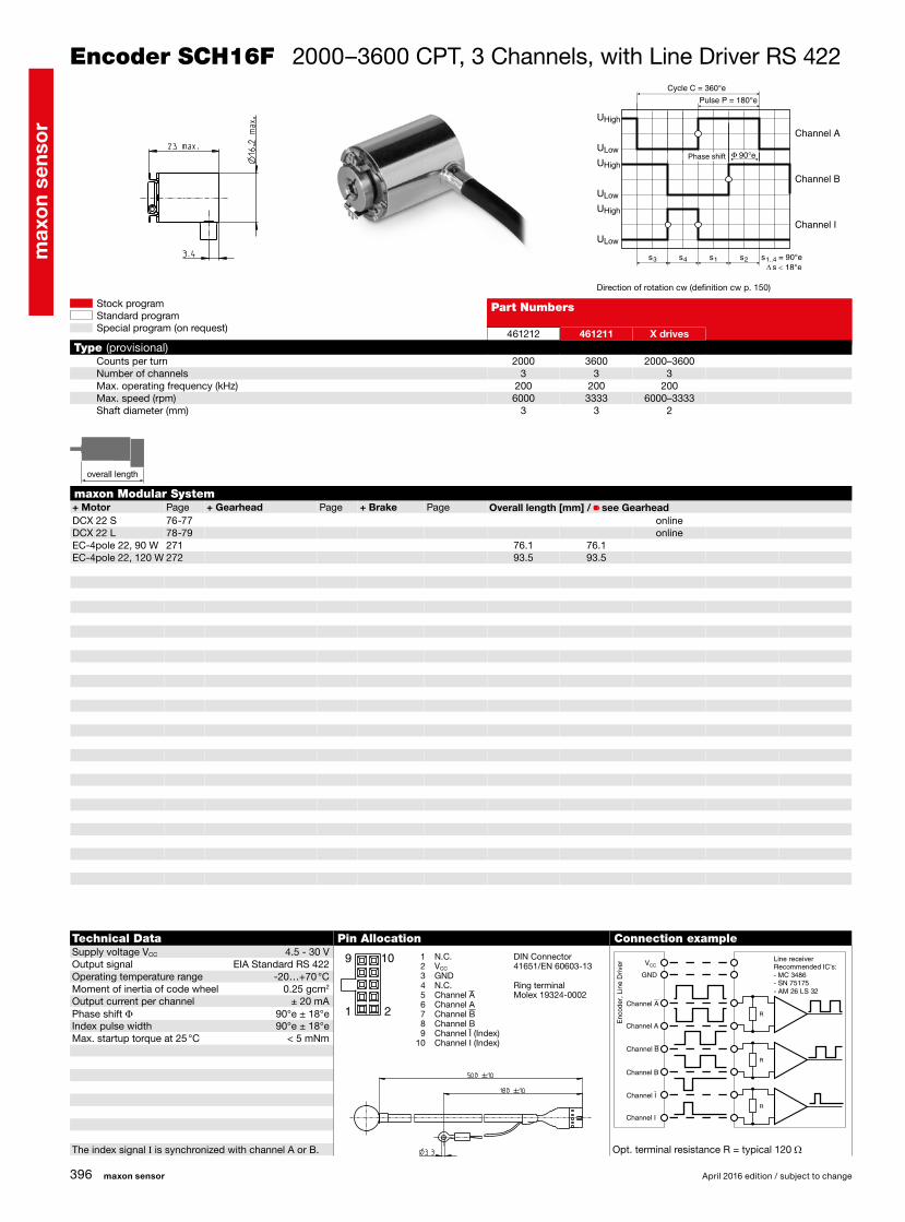
DCX 22 S 76-77 onlineDCX 22 L 78-79 onlineEC-4pole 22, 90 W 271 76.1 76.1EC-4pole 22, 120 W 272 93.5 93.5
461212 461211 X drives
2000 3600 2000–36003 3 3
200 200 2006000 3333 6000–3333
3 3 2
s∆ 18°e<s2 s = 90°e1..4s1s4s3
U
U
U
U
U
U
High
High
High
Low
Low
Low
90°e
R
R
R
maxon sensor April 2016 edition / subject to change
Stock programStandard programSpecial program (on request)
Encoder SCH16F 2000–3600 CPT, 3 Channels, with Line Driver RS 422
Part Numbers
Type (provisional)Counts per turnNumber of channelsMax. operating frequency (kHz)Max. speed (rpm)Shaft diameter (mm)
Direction of rotation cw (definition cw p. 150)
Technical Data Pin Allocation Connection exampleSupply voltage VCC 4.5 - 30 VOutput signal EIA Standard RS 422Operating temperature range -20…+70 °CMoment of inertia of code wheel 0.25 gcm2
Output current per channel ± 20 mAPhase shift Φ 90°e ± 18°eIndex pulse width 90°e ± 18°eMax. startup torque at 25 °C < 5 mNm
The index signal I is synchronized with channel A or B. Opt. terminal resistance R = typical 120 Ω
1 N.C. 2 VCC
3 GND 4 N.C. 5 Channel A 6 Channel A 7 Channel B 8 Channel B 9 Channel I (Index)10 Channel I (Index)
DIN Connector 41651/EN 60603-13
Ring terminalMolex 19324-0002
maxon Modular System+ Motor Page + Gearhead Page + Brake Page Overall length [mm] / • see Gearhead
Line receiverRecommended IC's:- MC 3486- SN 75175- AM 26 LS 32
Channel B
Channel B
Channel A
Channel A
Channel I
Channel I
GND
VCC
Enc
oder
, Lin
e D
river
Channel A
Channel B
Channel I
Cycle C = 360°e
Pulse P = 180°e
Phase shift
overall length overall length
max
on
sens
or
397
9
2
10
1
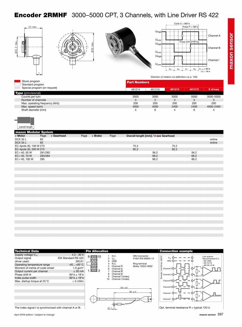
DCX 32 L 82 onlineDCX 35 L 83 onlineEC-4pole 30, 100 W 273 75.2 75.2EC-4pole 30, 200 W 275 92.2 92.2EC-i 40, 50 W 281/282 56.2 56.2EC-i 40, 70 W 283/284 66.2 66.2EC-i 40, 100 W 285 86.2 86.2
461214 461216 461213 461215 X drives
3000 3000 5000 5000 3000–50003 3 3 3 3
200 200 200 200 2004000 4000 2400 2400 4000–2400
4 6 4 6 4
s∆ 18°e<s2 s = 90°e1..4s1s4s3
U
U
U
U
U
U
High
High
High
Low
Low
Low
90°e
R
R
R
April 2016 edition / subject to change maxon sensor
Stock programStandard programSpecial program (on request)
Encoder 2RMHF 3000–5000 CPT, 3 Channels, with Line Driver RS 422
Part Numbers
Type (provisional)Counts per turnNumber of channelsMax. operating frequency (kHz)Max. speed (rpm)Shaft diameter (mm)
Direction of rotation cw (definition cw p. 150)
Technical Data Pin Allocation Connection exampleSupply voltage VCC 4.5 - 30 VOutput signal EIA Standard RS 422driver used: 26C31Operating temperature range -40…+85 °CMoment of inertia of code wheel 1.0 gcm2
Output current per channel ± 30 mAPhase shift Φ 90°e ± 18°eIndex pulse width 90°e ± 18°eMax. startup torque at 25 °C < 5 mNm
The index signal I is synchronized with channel A or B. Opt. terminal resistance R = typical 120 Ω
1 N.C. 2 VCC
3 GND 4 N.C. 5 Channel A 6 Channel A 7 Channel B 8 Channel B 9 Channel I (Index)10 Channel I (Index)
DIN Connector 41651/EN 60603-13
Ring terminalMolex 19324-0002
maxon Modular System+ Motor Page + Gearhead Page + Brake Page Overall length [mm] / • see Gearhead
Line receiverRecommended IC's:- MC 3486- SN 75175- AM 26 LS 32
Channel B
Channel B
Channel A
Channel A
Channel I
Channel I
GND
VCC
Enc
oder
, Lin
e D
river
, 26C
31
Channel A
Channel B
Channel I
Cycle C = 360°e
Pulse P = 180°e
Phase shift
overall length overall length

max
on
sens
or
398
RE 25 179/181 68.6RE 25 179/181 GP 26, 0.75 - 2.0 Nm 336 •RE 25 179/181 GP 32, 0.75 - 4.5 Nm 338 •RE 25 179/181 GP 32, 0.75 - 4.5 Nm 339 •RE 25 179/181 GP 32, 1.0 - 6.0 Nm 342 •RE 25 179/181 GP 32 S 370-372 •A-max 19, 1.5 W 198 43.3A-max 19, 1.5 W 198 GP 19, 0.1 - 0.3 Nm 325 •A-max 19, 1.5 W 198 GS 20, 0.06 - 0.25 Nm 326 •A-max 19, 1.5 W 198 GP 22, 0.1 - 2.0 Nm 329/331 •A-max 19, 1.5 W 198 GS 24, 0.1 Nm 335 •A-max 19, 1.5 W 198 GP 22 S 368/369 •A-max 19, 2.5 W 200 45.9A-max 19, 2.5 W 200 GP 19, 0.1 - 0.3 Nm 325 •A-max 19, 2.5 W 200 GP 22, 0.1 - 2.0 Nm 329/331 •A-max 19, 2.5 W 200 GS 24, 0.1 Nm 335 •A-max 19, 2.5 W 200 GP 22 S 368/369 •A-max 22 202/204 46.3A-max 22 202/204 GP 22, 0.1 - 0.3 Nm 327 •A-max 22 202/204 GP 22, 0.2 - 0.6 Nm 328 •A-max 22 202/204 GP 22, 0.1 - 2.0 Nm 327-331 •A-max 22 202/204 GS 24, 0.1 Nm 335 •A-max 22 202/204 GP 22 S 368/369 •A-max 26 206-212 59.1A-max 26 206-212 GP 26, 0.75 - 4.5 Nm 336 •A-max 26 206-212 GS 30, 0.07 - 0.2 Nm 337 •A-max 26 206-212 GP 32, 0.75 - 4.5 Nm 338 •A-max 26 206-212 GP 32, 0.75 - 4.5 Nm 339 •A-max 26 206-212 GP 32, 1.0 - 6.0 Nm 343 •A-max 26 206-212 GS 38, 0.1 - 0.6 Nm 348 •A-max 26 206-212 GP 32 S 370-372 •
500 ±10
103935 110520 110521
100 100 1002 2 220 20 20
12 000 12 000 12 0003 2 3
s∆ 45°e<s2 s = 90°e1..4s1s4s3
90°e
maxon sensor April 2016 edition / subject to change
Stock programStandard programSpecial program (on request)
Encoder Enc 22 100 CPT, 2 Channels
maxon Modular System+ Motor Page + Gearhead Page Overall length [mm] / • see Gearhead
Part Numbers
TypeCounts per turnNumber of channelsMax. operating frequency (kHz)Max. speed (rpm)Shaft diameter (mm)
Direction of rotation cw (definition cw p. 150)
Technical Data Pin Allocation Connection exampleSupply voltage VCC 5 V ± 10%
Order number for connector with cable: 3419.506
Output signal TTL compatiblePhase shift Φ 90°e ± 45°eSignal rise time (typically, at CL = 25 pF, RL = 11 kW, 25 °C) 200 nsSignal fall time (typically, at CL = 25 pF, RL = 11 kW, 25 °C) 50 nsOperating temperature range -20…+85 °CMoment of inertia of code wheel ≤ 0.05 gcm2
Output current per channel min. -1 mA, max. 5 mA
Ambient temperature range JU = 22 - 25 °C
Micromodule contact stripType Lumberg MICS 4Pin 4 GNDPin 3 Channel APin 2 VCC, Pin 1 Channel Brecommended connectors:Micromodule connectorType Lumberg MICA 4
Channel A
Channel B
VCC 5 VDC 5 %
Rpull-up 3.3 k
GND
Channel A
Channel B
Cycle C = 360°e
Pulse P = 180°e
Phase shift
overall length overall length

max
on
sens
or
399
RE 25 179/181 75.3RE 25 179/181 GP 26, 0.75 - 2.0 Nm 336 •RE 25 179/181 GP 32, 0.75 - 6.0 Nm 338-342 •RE 25 179/181 KD 32, 1.0 - 4.5 Nm 347 •RE 25 179/181 GP 32 S 370-372 •RE 25, 20 W 181 AB 28 446 105.8RE 25, 20 W 181 GP 26, 0.75 - 2.0 Nm 336 AB 28 446 •RE 25, 20 W 181 GP 32, 0.75 - 6.0 Nm 338-342 AB 28 446 •RE 25, 20 W 181 KD 32, 1.0 - 4.5 Nm 347 AB 28 446 •RE 25, 20 W 181 GP 32 S 370-372 AB 28 446 •RE 30, 15 W 182 88.8RE 30, 15 W 182 GP 32, 0.75 - 4.5 Nm 340 •RE 30, 60 W 183 88.8RE 30, 60 W 183 GP 32, 0.75 - 6.0 Nm 338-344 •RE 30, 60 W 183 KD 32, 1.0 - 4.5 Nm 347 •RE 30, 60 W 183 GP 32 S 370-372 •RE 35, 90 W 184 91.7RE 35, 90 W 184 GP 32, 0.75 - 8.0 Nm 338-345 •RE 35, 90 W 184 GP 42, 3.0 - 15 Nm 349 •RE 35, 90 W 184 GP 32 S 370-372 •RE 35, 90 W 184 AB 28 446 124.3RE 35, 90 W 184 GP 32, 0.75 - 8.0 Nm 338-345 AB 28 446 •RE 35, 90 W 184 GP 42, 3.0 - 15 Nm 349 AB 28 446 •RE 35, 90 W 184 GP 32 S 370-372 AB 28 446 •RE 40, 25 W 185 91.7RE 40, 150 W 186 91.7RE 40, 150 W 186 GP 42, 3.0 - 15 Nm 349 •RE 40, 150 W 186 GP 52, 4.0 - 30 Nm 354 •RE 40, 150 W 186 AB 28 446 124.3RE 40, 150 W 186 GP 42, 3.0 - 15 Nm 349 AB 28 446 •RE 40, 150 W 186 GP 52, 4.0 - 30 Nm 354 AB 28 446 •
110511 110513 110515
500 500 5003 3 3
100 100 100 12 000 12 000 12 000
3 4 6
s∆ 45°e<s2 s = 90°e1..4s1s4s3
U
U
U
U
U
U
High
High
High
Low
Low
Low
90°e
April 2016 edition / subject to change maxon sensor
Stock programStandard programSpecial program (on request)
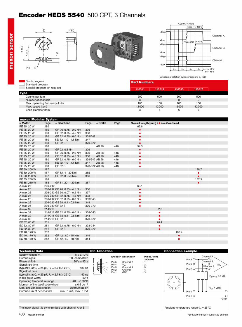
Encoder HEDS 5540 500 CPT, 3 Channels
maxon Modular System+ Motor Page + Gearhead Page + Brake Page Overall length [mm] / • see Gearhead
Part Numbers
TypeCounts per turnNumber of channelsMax. operating frequency (kHz)Max. speed (rpm)Shaft diameter (mm)
Direction of rotation cw (definition cw p. 150)
Technical Data Pin Allocation Connection exampleSupply voltage VCC 5 V ± 10%Output signal TTL compatiblePhase shift Φ 90°e ± 45°eSignal rise time (typically, at CL = 25 pF, RL = 2.7 kW, 25 °C) 180 nsSignal fall time (typically, at CL = 25 pF, RL = 2.7 kW, 25 °C) 40 nsIndex pulse width (nominal) 90°eOperating temperature range -40…+100 °CMoment of inertia of code wheel ≤ 0.6 gcm2
Max. angular acceleration 250 000 rad s-2
Output current per channel min. -1 mA, max. 5 mA
The index signal I is synchronized with channel A or B. Ambient temperature range JU = 25 °C
Encoder Description Pin no. from 3409.506Pin 5 Channel B 1Pin 4 VCC 2Pin 3 Channel A 3Pin 2 Channel I 4Pin 1 GND 5
Channel A
Channel B
Channel I
VCC 5 VDC
Rpull-up 3.3 k
GND
TTL
Pin 3
Pin 5
Pin 2
Pin 4
Pin 1
Channel A
Channel B
Channel I
Cycle C = 360°e
Pulse P = 180°e
Phase shift
overall length overall length
max
on
sens
or
400
RE 25, 20 W 180 63.8RE 25, 20 W 180 GP 26, 0.75 - 2.0 Nm 336 •RE 25, 20 W 180 GP 32, 0.75 - 4.5 Nm 338 •RE 25, 20 W 180 GP 32, 0.75 - 6.0 Nm 339/342 •RE 25, 20 W 180 KD 32, 1.0 - 4.5 Nm 347 •RE 25, 20 W 180 GP 32 S 370-372 •RE 25, 20 W 180 AB 28 446 94.3RE 25, 20 W 180 GP 22, 0.5 Nm 329 •RE 25, 20 W 180 GP 26, 0.75 - 2.0 Nm 336 AB 28 446 •RE 25, 20 W 180 GP 32, 0.75 - 4.5 Nm 338 AB 28 446 •RE 25, 20 W 180 GP 32, 0.75 - 6.0 Nm 339/342 AB 28 446 •RE 25, 20 W 180 KD 32, 1.0 - 4.5 Nm 347 AB 28 446 •RE 25, 20 W 180 GP 32 S 370-372 AB 28 446 •RE 50, 200 W 187 128.7RE 50, 200 W 187 GP 52, 4 - 30 Nm 355 •RE 50, 200 W 187 GP 62, 8 - 50 Nm 356 •RE 65, 250 W 188 157.3RE 65, 250 W 188 GP 81, 20 - 120 Nm 357 •A-max 26 206-212 63.1A-max 26 206-212 GP 26, 0.75 - 4.5 Nm 336 •A-max 26 206-212 GS 30, 0.07 - 0.2 Nm 337 •A-max 26 206-212 GP 32, 0.75 - 4.5 Nm 338 •A-max 26 206-212 GP 32, 0.75 - 6.0 Nm 339/343 •A-max 26 206-212 GS 38, 0.1 - 0.6 Nm 348 •A-max 26 206-212 GP 32 S 370-372 •A-max 32 214/216 82.3A-max 32 214/216 GP 32, 0.75 - 6.0 Nm 338-343 •A-max 32 214/216 GS 38, 0.1 - 0.6 Nm 348 •A-max 32 214/216 GP 32 S 370-372 •EC 32, 80 W 251 78.4EC 32, 80 W 251 GP 32, 0.75 - 6.0 Nm 338-344 •EC 32, 80 W 251 GP 32 S 370-372 •EC 40, 170 W 252 103.4EC 40, 170 W 252 GP 42, 3.0 - 15 Nm 349 •EC 40, 170 W 252 GP 52, 4.0 - 30 Nm 354 •
110511 110513 110515 110517
500 500 500 5003 3 3 3
100 100 100 10012 000 12 000 12 000 12 000
3 4 6 8
s∆ 45°e<s2 s = 90°e1..4s1s4s3
U
U
U
U
U
U
High
High
High
Low
Low
Low
90°e
maxon sensor April 2016 edition / subject to change
Stock programStandard programSpecial program (on request)
Encoder HEDS 5540 500 CPT, 3 Channels
maxon Modular System+ Motor Page + Gearhead Page + Brake Page Overall length [mm] / • see Gearhead
Part Numbers
TypeCounts per turnNumber of channelsMax. operating frequency (kHz)Max. speed (rpm)Shaft diameter (mm)
Direction of rotation cw (definition cw p. 150)
Technical Data Pin Allocation Connection exampleSupply voltage VCC 5 V ± 10%Output signal TTL compatiblePhase shift Φ 90°e ± 45°eSignal rise time (typically, at CL = 25 pF, RL = 2.7 kW, 25 °C) 180 nsSignal fall time (typically, at CL = 25 pF, RL = 2.7 kW, 25 °C) 40 nsIndex pulse width 90°eOperating temperature range -40…+100 °CMoment of inertia of code wheel ≤ 0.6 gcm2
Max. angular acceleration 250 000 rad s-2
Output current per channel min. -1 mA, max. 5 mA
The index signal I is synchronized with channel A or B. Ambient temperature range JU = 25 °C
Encoder Description Pin no. from 3409.506Pin 5 Channel B 1Pin 4 VCC 2Pin 3 Channel A 3Pin 2 Channel I 4Pin 1 GND 5
Channel A
Channel B
Channel I
VCC 5 VDC
Rpull-up 3.3 k
GND
TTL
Pin 3
Pin 5
Pin 2
Pin 4
Pin 1
Channel A
Channel B
Channel I
Cycle C = 360°e
Pulse P = 180°e
Phase shift
max
on
sens
or
401
RE 25 179/181 75.3RE 25 179/181 GP 26/GP 32 336/338 •RE 25 179/181 KD 32, 1.0 - 4.5 Nm 347 •RE 25 179/181 GP 32, 0.75 - 6.0 Nm 339/342 •RE 25 179/181 GP 32 S 370-372 •RE 25, 20 W 180 63.8RE 25, 20 W 180 GP 26/GP 32 336/338 •RE 25, 20 W 180 KD 32, 1.0 - 4.5 Nm 347 •RE 25, 20 W 180 GP 32, 0.75 - 6.0 Nm 339/342 •RE 25, 20 W 180 GP 32 S 370-372 •RE 25, 20 W 180 AB 28 446 94.3RE 25, 20 W 180 GP 26/GP 32 336/338 AB 28 446 •RE 25, 20 W 180 KD 32, 1.0 - 4.5 Nm 347 AB 28 446 •RE 25, 20 W 180 GP 32, 0.75 - 6.0 Nm 339/342 AB 28 446 •RE 25, 20 W 180 GP 32 S 370-372 AB 28 446 •RE 25, 20 W 181 AB 28 446 105.8RE 25, 20 W 181 GP 26/GP 32 336/338 AB 28 446 •RE 25, 20 W 181 KD 32, 1.0 - 4.5 Nm 347 AB 28 446 •RE 25, 20 W 181 GP 32, 0.75 - 6.0 Nm 339/342 AB 28 446 •RE 25, 20 W 181 GP 32 S 370-372 AB 28 446 •RE 30, 15 W 182 88.8RE 30, 15 W 182 GP 32, 0.75 - 4.5 Nm 340 •RE 30, 60 W 183 88.8RE 30, 60 W 183 GP 32, 0.75 - 6.0 Nm 338-344 •RE 30, 60 W 183 KD 32, 1.0 - 4.5 Nm 347 •RE 30, 60 W 183 GP 32 S 370-372 •RE 35, 90 W 184 91.7RE 35, 90 W 184 GP 32, 0.75 - 8.0 Nm 338-345 •RE 35, 90 W 184 GP 42, 3.0 - 15 Nm 349 •RE 35, 90 W 184 GP 32 S 370-372 •RE 35, 90 W 184 AB 28 446 124.3RE 35, 90 W 184 GP 32, 0.75 - 8.0 Nm 338-345 AB 28 446 •RE 35, 90 W 184 GP 42, 3.0 - 15 Nm 349 AB 28 446 •RE 35, 90 W 184 GP 32 S 370-372 AB 28 446 •
1
9
2
10
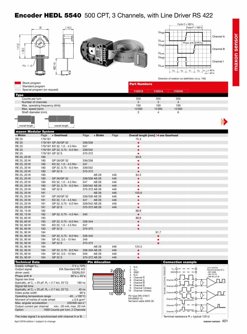
110512 110514 110516
500 500 5003 3 3
100 100 100 12 000 12 000 12 000
3 4 6
s∆ 45°e<s2 s = 90°e1..4s1s4s3
U
U
U
U
U
U
High
High
High
Low
Low
Low
90°e
R
R
R
April 2016 edition / subject to change maxon sensor
Stock programStandard programSpecial program (on request)
Encoder HEDL 5540 500 CPT, 3 Channels, with Line Driver RS 422
maxon Modular System+ Motor Page + Gearhead Page + Brake Page Overall length [mm] / • see Gearhead
Part Numbers
TypeCounts per turnNumber of channelsMax. operating frequency (kHz)Max. speed (rpm)Shaft diameter (mm)
Direction of rotation cw (definition cw p. 150)
Technical Data Pin Allocation Connection exampleSupply voltage VCC 5 V ± 10%Output signal EIA Standard RS 422 driver used: DS26LS31Phase shift Φ 90°e ± 45°eSignal rise time (typically, at CL = 25 pF, RL = 2.7 kW, 25 °C) 180 nsSignal fall time (typically, at CL = 25 pF, RL = 2.7 kW, 25 °C) 40 nsIndex pulse width 90°eOperating temperature range -40…+100 °CMoment of inertia of code wheel ≤ 0.6 gcm2
Max. angular acceleration 250 000 rad s-2
Output current per channel min. -20 mA, max. 20 mAOption 1000 Counts per turn, 2 Channels
The index signal I is synchronized with channel A or B. Terminal resistance R = typical 120 W
1 N.C. 2 VCC
3 GND 4 N.C. 5 Channel A 6 Channel A 7 Channel B 8 Channel B 9 Channel I (Index)10 Channel I (Index)
Pin type DIN 41651/EN 60603-13flat band cable AWG 28
Line receiverRecommended IC's:- MC 3486- SN 75175- AM 26 LS 32
Channel B
Channel B
Channel A
Channel A
Channel I
Channel I
GND
VCC
Enc
oder
, Lin
e D
river
, DS
26LS
31
Channel A
Channel B
Channel I
Cycle C = 360°e
Pulse P = 180°e
Phase shift
overall length overall length

max
on
sens
or
402
110512 110514 110516 110518
500 500 500 5003 3 3 3
100 100 100 100 12 000 12 000 12 000 12 000
3 4 6 8
RE 40, 25 W 185 91.7RE 40, 150 W 186 91.7RE 40, 150 W 186 GP 42, 3.0 - 15 Nm 349 •RE 40, 150 W 186 GP 52, 4.0 - 30 Nm 354 •RE 40, 150 W 186 AB 28 446 124.3RE 40, 150 W 186 GP 42, 3.0 - 15 Nm 349 AB 28 446 •RE 40, 150 W 186 GP 52, 4.0 - 30 Nm 354 AB 28 446 •RE 50, 200 W 187 128.7RE 50, 200 W 187 GP 52, 4 - 30 Nm 355 •RE 50, 200 W 187 GP 62, 8 - 50 Nm 356 •RE 65, 250 W 188 157.3RE 65, 250 W 188 GP 81, 20 - 120 Nm 357 •A-max 26 206-212 63.1A-max 26 206-212 GP 26, 0.75 - 4.5 Nm 336 •A-max 26 206-212 GS 30/GP 32 337/340 •A-max 26 206-212 GP 32, 0.75 - 6.0 Nm 339/343 •A-max 26 206-212 GS 38, 0.1 - 0.6 Nm 348 •A-max 26 206-212 GP 32 S 370-372 •A-max 32 214/216 82.3A-max 32 214/216 GP 32, 0.75 - 6.0 Nm 338-343 •A-max 32 214/216 GS 38, 0.1 - 0.6 Nm 348 •A-max 32 214/216 GP 32 S 370-372 •EC 32, 80 W 251 78.4EC 32, 80 W 251 GP 32, 0.75 - 6.0 Nm 338-344 •EC 32, 80 W 251 GP 32 S 370-372 •EC 40, 170 W 252 103.4EC 40, 170 W 252 GP 42, 3.0 - 15 Nm 349 •EC 40, 170 W 252 GP 52, 4.0 - 30 Nm 354 •
1
9
2
10
s∆ 45°e<s2 s = 90°e1..4s1s4s3
U
U
U
U
U
U
High
High
High
Low
Low
Low
90°e
R
R
R
maxon sensor April 2016 edition / subject to change
Stock programStandard programSpecial program (on request)
Encoder HEDL 5540 500 CPT, 3 Channels, with Line Driver RS 422
maxon Modular System+ Motor Page + Gearhead Page + Brake Page Overall length [mm] / • see Gearhead
Part Numbers
TypeCounts per turnNumber of channelsMax. operating frequency (kHz)Max. speed (rpm)Shaft diameter (mm)
Direction of rotation cw (definition cw p. 150)
Technical Data Pin Allocation Connection exampleSupply voltage VCC 5 V ± 10%Output signal EIA Standard RS 422 driver used: DS26LS31Phase shift Φ 90°e ± 45°eSignal rise time (typically, at CL = 25 pF, RL = 2.7 kW, 25 °C) 180 nsSignal fall time (typically, at CL = 25 pF, RL = 2.7 kW, 25 °C) 40 nsIndex pulse width 90°eOperating temperature range -40…+100 °CMoment of inertia of code wheel ≤ 0.6 gcm2
Max. angular acceleration 250 000 rad s-2
Output current per channel min. -20 mA, max. 20 mAOption 1000 Counts per turn, 2 Channels
The index signal I is synchronized with channel A or B. Terminal resistance R = typical 120 W
1 N.C. 2 VCC
3 GND 4 N.C. 5 Channel A 6 Channel A 7 Channel B 8 Channel B 9 Channel I (Index)10 Channel I (Index)
Pin type DIN 41651/EN 60603-13flat band cable AWG 28
Line receiverRecommended IC's:- MC 3486- SN 75175- AM 26 LS 32
Channel B
Channel B
Channel A
Channel A
Channel I
Channel I
GND
VCC
Enc
oder
, Lin
e D
river
, DS
26LS
31
Channel A
Channel B
Channel I
Cycle C = 360°e
Pulse P = 180°e
Phase shift
overall length overall length

max
on
sens
or
403
110512 110514 110516
500 500 5003 3 3
100 100 100 12 000 12 000 12 000
3 4 6
EC-max 30, 40 W 264 62.6EC-max 30, 40 W 264 GP 32, 1.0 - 8.0 Nm 343/345 •EC-max 30, 40 W 264 KD 32, 1.0 - 4.5 Nm 347 •EC-max 30, 40 W 264 GP 32 S 370-372 •EC-max 30, 40 W 264 AB 20 444 98.4EC-max 30, 40 W 264 GP 32, 1.0 - 8.0 Nm 343/345 AB 20 444 •EC-max 30, 40 W 264 KD 32, 1.0 - 4.5 Nm 347 AB 20 444 •EC-max 30, 40 W 264 GP 32 S 370-372 AB 20 444 •EC-max 30, 60 W 265 84.6EC-max 30, 60 W 265 GP 32, 1.0 - 8.0 Nm 343/345 •EC-max 30, 60 W 265 KD 32, 1.0 - 4.5 Nm 347 •EC-max 30, 60 W 265 GP 42, 3 - 15 Nm 350 •EC-max 30, 60 W 265 AB 20 444 120.4EC-max 30, 60 W 265 GP 32, 1.0 - 8.0 Nm 343/345 AB 20 444 •EC-max 30, 60 W 265 KD 32, 1.0 - 4.5 Nm 347 AB 20 444 •EC-max 30, 60 W 265 GP 42, 3 - 15 Nm 350 AB 20 444 •EC-max 40, 70 W 266 81.4EC-max 40, 70 W 266 GP 42, 3 - 15 Nm 350 •EC-max 40, 70 W 266 AB 28 445 110.7EC-max 40, 70 W 266 GP 42, 3 - 15 Nm 350 AB 28 445 •EC-max 40, 120 W 267 111.4EC-max 40, 120 W 267 GP 52, 4 - 30 Nm 355 •EC-max 40, 120 W 267 AB 28 445 140.7EC-max 40, 120 W 267 GP 52, 4 - 30 Nm 355 AB 28 445 •EC-4pole 22, 90 W 271 70.1EC-4pole 22, 90 W 271 GP 22/GP 32 333/343 •EC-4pole 22, 90 W 271 GP 32 S 370-372 •EC-4pole 22, 120 W 272 87.5EC-4pole 22, 120 W 272 GP 22/GP 32 333/343 •EC-4pole 22, 120 W 272 GP 32 S 370-372 •
1
9
2
10
s∆ 45°e<s2 s = 90°e1..4s1s4s3
U
U
U
U
U
U
High
High
High
Low
Low
Low
90°e
R
R
R
April 2016 edition / subject to change maxon sensor
Stock programStandard programSpecial program (on request)
Encoder HEDL 5540 500 CPT, 3 Channels, with Line Driver RS 422
maxon Modular System+ Motor Page + Gearhead Page + Brake Page Overall length [mm] / • see Gearhead
Part Numbers
TypeCounts per turnNumber of channelsMax. operating frequency (kHz)Max. speed (rpm)Shaft diameter (mm)
Direction of rotation cw (definition cw p. 150)
Technical Data Pin Allocation Connection exampleSupply voltage VCC 5 V ± 10%Output signal EIA Standard RS 422 driver used: DS26LS31Phase shift Φ 90°e ± 45°eSignal rise time (typically, at CL = 25 pF, RL = 2.7 kW, 25 °C) 180 nsSignal fall time (typically, at CL = 25 pF, RL = 2.7 kW, 25 °C) 40 nsIndex pulse width 90°eOperating temperature range -40…+100 °CMoment of inertia of code wheel ≤ 0.6 gcm2
Max. angular acceleration 250 000 rad s-2
Output current per channel min. -20 mA, max. 20 mAOption 1000 Counts per turn, 2 Channels
The index signal I is synchronized with channel A or B. Terminal resistance R = typical 120 W
1 N.C. 2 VCC
3 GND 4 N.C. 5 Channel A 6 Channel A 7 Channel B 8 Channel B 9 Channel I (Index)10 Channel I (Index)
Pin type DIN 41651/EN 60603-13flat band cable AWG 28
Line receiverRecommended IC's:- MC 3486- SN 75175- AM 26 LS 32
Channel B
Channel B
Channel A
Channel A
Channel I
Channel I
GND
VCC
Enc
oder
, Lin
e D
river
, DS
26LS
31
Channel A
Channel B
Channel I
Cycle C = 360°e
Pulse P = 180°e
Phase shift
overall length overall length

max
on
sens
or
404
EC-4pole 30, 100 W 273 67.6EC-4pole 30, 100 W 273 GP 32, 4.0 - 8.0 Nm 345 •EC-4pole 30, 100 W 273 GP 42, 3 - 15 Nm 350 •EC-4pole 30, 100 W 273 AB 20 444 104.0EC-4pole 30, 100 W 273 GP 32, 4.0 - 8.0 Nm 345 AB 20 444 •EC-4pole 30, 100 W 273 GP 42, 3 - 15 Nm 350 AB 20 444 •EC-4pole 30, 200 W 275 84.6EC-4pole 30, 200 W 275 GP 32, 4.0 - 8.0 Nm 345 •EC-4pole 30, 200 W 275 GP 42, 3 - 15 Nm 350 •EC-4pole 30, 200 W 275 AB 20 444 121.0EC-4pole 30, 200 W 275 GP 32, 4.0 - 8.0 Nm 345 AB 20 444 •EC-4pole 30, 200 W 275 GP 42, 3 - 15 Nm 350 AB 20 444 •EC-i 40, 50 W 281/282 49.0EC-i 40, 50 W 281 GP 32, 1 - 6 Nm 343 •EC-i 40, 50 W 281/282 GP 42, 3 - 15 Nm 350 •EC-i 40, 50 W 281 GP 32 S 370-372 •EC-i 40, 70 W 283/284 59.0EC-i 40, 70 W 283 GP 32, 1 - 6 Nm 343 •EC-i 40, 70 W 283/284 GP 42, 3 - 15 Nm 350 •EC-i 40, 70 W 283 GP 32 S 370-372 •EC-i 40, 100 W 285 79.0EC-i 40, 100 W 285 GP 42, 3 - 15 Nm 350 •EC-i 52, 180 W 286 100.7EC-i 52, 180 W 286 GP 52, 4 - 30 Nm 354 •DCX 22 S 76-77 onlineDCX 22 L 78-79 onlineDCX 26 L 80-81 onlineDCX 32 L 82 onlineDCX 35 L 83 online
1
9
2
10
110512 110514 110516 110518 X drives
500 500 500 500 5003 3 3 3 3
100 100 100 100 100 12 000 12 000 12 000 12 000 12 000
3 4 6 8 2–4
s∆ 45°e<s2 s = 90°e1..4s1s4s3
U
U
U
U
U
U
High
High
High
Low
Low
Low
90°e
R
R
R
maxon sensor April 2016 edition / subject to change
Stock programStandard programSpecial program (on request)
Encoder HEDL 5540 500 CPT, 3 Channels, with Line Driver RS 422
maxon Modular System+ Motor Page + Gearhead Page + Brake Page Overall length [mm] / • see Gearhead
Part Numbers
TypeCounts per turnNumber of channelsMax. operating frequency (kHz)Max. speed (rpm)Shaft diameter (mm)
Direction of rotation cw (definition cw p. 150)
Technical Data Pin Allocation Connection exampleSupply voltage VCC 5 V ± 10%Output signal EIA Standard RS 422 driver used: DS26LS31Phase shift Φ 90°e ± 45°eSignal rise time (typically, at CL = 25 pF, RL = 2.7 kW, 25 °C) 180 nsSignal fall time (typically, at CL = 25 pF, RL = 2.7 kW, 25 °C) 40 nsIndex pulse width 90°eOperating temperature range -40…+100 °CMoment of inertia of code wheel ≤ 0.6 gcm2
Max. angular acceleration 250 000 rad s-2
Output current per channel min. -20 mA, max. 20 mAOption 1000 Counts per turn, 2 Channels
The index signal I is synchronized with channel A or B. Terminal resistance R = typical 120 W
1 N.C. 2 VCC
3 GND 4 N.C. 5 Channel A 6 Channel A 7 Channel B 8 Channel B 9 Channel I (Index)10 Channel I (Index)
Pin type DIN 41651/EN 60603-13flat band cable AWG 28
Line receiverRecommended IC's:- MC 3486- SN 75175- AM 26 LS 32
Channel B
Channel B
Channel A
Channel A
Channel I
Channel I
GND
VCC
Enc
oder
, Lin
e D
river
, DS
26LS
31
Channel A
Channel B
Channel I
Cycle C = 360°e
Pulse P = 180°e
Phase shift
overall length overall length
max
on
sens
or
405
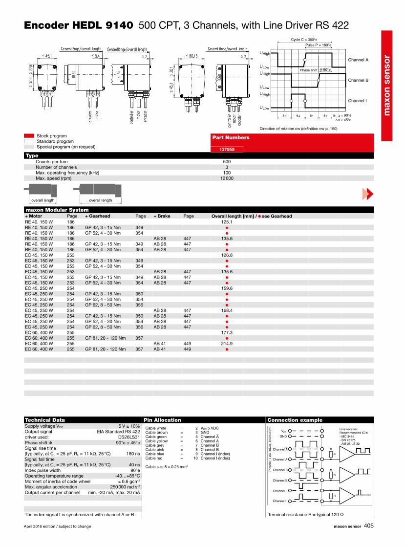
RE 40, 150 W 186 125.1RE 40, 150 W 186 GP 42, 3 - 15 Nm 349 •RE 40, 150 W 186 GP 52, 4 - 30 Nm 354 •RE 40, 150 W 186 AB 28 447 135.6RE 40, 150 W 186 GP 42, 3 - 15 Nm 349 AB 28 447 •RE 40, 150 W 186 GP 52, 4 - 30 Nm 354 AB 28 447 •EC 45, 150 W 253 126.8EC 45, 150 W 253 GP 42, 3 - 15 Nm 349 •EC 45, 150 W 253 GP 52, 4 - 30 Nm 354 •EC 45, 150 W 253 AB 28 447 135.6EC 45, 150 W 253 GP 42, 3 - 15 Nm 349 AB 28 447 •EC 45, 150 W 253 GP 52, 4 - 30 Nm 354 AB 28 447 •EC 45, 250 W 254 159.6EC 45, 250 W 254 GP 42, 3 - 15 Nm 350 •EC 45, 250 W 254 GP 52, 4 - 30 Nm 354 •EC 45, 250 W 254 GP 62, 8 - 50 Nm 356 •EC 45, 250 W 254 AB 28 447 168.4EC 45, 250 W 254 GP 42, 3 - 15 Nm 350 AB 28 447 •EC 45, 250 W 254 GP 52, 4 - 30 Nm 354 AB 28 447 •EC 45, 250 W 254 GP 62, 8 - 50 Nm 356 AB 28 447 •EC 60, 400 W 255 177.3EC 60, 400 W 255 GP 81, 20 - 120 Nm 357 •EC 60, 400 W 255 AB 41 449 214.9EC 60, 400 W 255 GP 81, 20 - 120 Nm 357 AB 41 449 •
137959
5003
100 12 000
s∆ 45°e<s2 s = 90°e1..4s1s4s3
U
U
U
U
U
U
High
High
High
Low
Low
Low
90°e
R
R
R
April 2016 edition / subject to change maxon sensor
Stock programStandard programSpecial program (on request)
Encoder HEDL 9140 500 CPT, 3 Channels, with Line Driver RS 422
Direction of rotation cw (definition cw p. 150)
Technical Data Pin Allocation Connection exampleSupply voltage VCC 5 V ± 10%Output signal EIA Standard RS 422 driver used: DS26LS31Phase shift Φ 90°e ± 45°eSignal rise time (typically, at CL = 25 pF, RL = 11 kW, 25 °C) 180 nsSignal fall time (typically, at CL = 25 pF, RL = 11 kW, 25 °C) 40 nsIndex pulse width 90°eOperating temperature range -40…+85 °CMoment of inertia of code wheel ≤ 0.6 gcm2
Max. angular acceleration 250 000 rad s-2
Output current per channel min. -20 mA, max. 20 mA
The index signal I is synchronized with channel A or B. Terminal resistance R = typical 120 W
Cable white = 2 VCC 5 VDCCable brown = 3 GNDCable green = 5 Channel A Cable yellow = 6 Channel ACable grey = 7 Channel BCable pink = 8 Channel BCable blue = 9 Channel I (Index)Cable red = 10 Channel I (Index)
Cable size 8 × 0.25 mm2
maxon Modular System+ Motor Page + Gearhead Page + Brake Page Overall length [mm] / • see Gearhead
Part Numbers
TypeCounts per turnNumber of channelsMax. operating frequency (kHz)Max. speed (rpm)
Line receiverRecommended IC's:- MC 3486- SN 75175- AM 26 LS 32
Channel B
Channel B
Channel A
Channel A
Channel I
Channel I
GND
VCC
Enc
oder
, Lin
e D
river
, DS
26LS
31
Channel A
Channel B
Channel I
Cycle C = 360°e
Pulse P = 180°e
Phase shift
overall length overall length

max
on
sens
or
406
RE 50, 200 W 187 170.4RE 50, 200 W 187 GP 52, 4 - 30 Nm 355 •RE 50, 200 W 187 GP 62, 8 - 50 Nm 356 •RE 50, 200 W 187 AB 44 450 183.4RE 50, 200 W 187 GP 52, 4 - 30 Nm 355 AB 44 450 •RE 50, 200 W 187 GP 62, 8 - 50 Nm 356 AB 44 450 •RE 65, 250 W 188 187.5RE 65, 250 W 188 GP 81, 20 - 120 Nm 357 •RE 65, 250 W 188 AB 44 450 205.5RE 65, 250 W 188 GP 81, 20 - 120 Nm 357 AB 44 450 •
386051 386001386053 386002
500 5003 3
100 100 12 000 12 000
s∆ 45°e<s2 s = 90°e1..4s1s4s3
U
U
U
U
U
U
High
High
High
Low
Low
Low
90°e
R
R
R
maxon sensor April 2016 edition / subject to change
Stock programStandard programSpecial program (on request)
Encoder HEDL 9140 500 CPT, 3 Channels, with Line Driver RS 422
Direction of rotation cw (definition cw p. 150)
Technical Data Pin Allocation Connection exampleSupply voltage VCC 5 V ± 10%Output signal EIA Standard RS 422 driver used: DS26LS31Phase shift Φ 90°e ± 45°eSignal rise time (typically, at CL = 25 pF, RL = 11 kW, 25 °C) 180 nsSignal fall time (typically, at CL = 25 pF, RL = 11 kW, 25 °C) 40 nsIndex pulse width 90°eOperating temperature range -40…+85 °CMoment of inertia of code wheel ≤ 0.6 gcm2
Max. angular acceleration 250 000 rad s-2
Output current per channel min. -20 mA, max. 20 mAProtection to IP54
The index signal I is synchronized with channel A or B. Terminal resistance R = typical 120 W
EncoderCable white = VCC 5 VDCCable brown = GNDCable green = Channel A Cable yellow = Channel ACable grey = Channel BCable pink = Channel BCable blue = Channel I (Index)Cable red = Channel I (Index)Cable size 8 × 0.25 mm2
MotorCable white = Motor +Cable brown = Motor -Cable size 2 × 1.0 mm2
maxon Modular System+ Motor Page + Gearhead Page + Brake Page Overall length [mm] / • see Gearhead
Part Numbers
cable outlet axialcable outlet radial
TypeCounts per turnNumber of channelsMax. operating frequency (kHz)Max. speed (rpm)
Line receiverRecommended IC's:- MC 3486- SN 75175- AM 26 LS 32
Channel B
Channel B
Channel A
Channel A
Channel I
Channel I
GND
VCC
Enc
oder
, Lin
e D
river
, DS
26LS
31
Channel A
Channel B
Channel I
Cycle C = 360°e
Pulse P = 180°e
Phase shift
overall length overall length

max
on
sens
or
407
EC-4pole 22, 90 W 271 70.1 70.1EC-4pole 22, 90 W 271 GP 22/GP 32 333/343 • •EC-4pole 22, 90 W 271 GP 32 S 370-372 • •EC-4pole 22, 120 W 272 87.5 87.5EC-4pole 22, 120 W 272 GP 22/GP 32 333/343 • •EC-4pole 22, 120 W 272 GP 32 S 370-372 • •EC-4pole 30, 100 W 273 67.6 67.6EC-4pole 30, 100 W 273 GP 32, 4.0 - 8.0 Nm 345 • •EC-4pole 30, 100 W 273 GP 42, 3 - 15 Nm 350 • •EC-4pole 30, 100 W 273 AB 20 444 104.0 104.0EC-4pole 30, 100 W 273 GP 32, 4.0 - 8.0 Nm 345 AB 20 444 • •EC-4pole 30, 100 W 273 GP 42, 3 - 15 Nm 350 AB 20 444 • •EC-4pole 30, 200 W 275 84.6 84.6EC-4pole 30, 200 W 275 GP 32, 4.0 - 8.0 Nm 345 • •EC-4pole 30, 200 W 275 GP 42, 3 - 15 Nm 350 • •EC-4pole 30, 200 W 275 AB 20 444 121.0 121.0EC-4pole 30, 200 W 275 GP 32, 4.0 - 8.0 Nm 345 AB 20 444 • •EC-4pole 30, 200 W 275 GP 42, 3 - 15 Nm 350 AB 20 444 • •EC-i 40, 50 W 282 49.0EC-i 40, 50 W 282 GP 32, 1 - 6 Nm 343 •EC-i 40, 50 W 282 GP 42, 3 - 15 Nm 350 •EC-i 40, 50 W 282 GP 32 S 370-372 •EC-i 40, 70 W 283/284 59.0EC-i 40, 70 W 283 GP 32, 1 - 6 Nm 343 •EC-i 40, 70 W 283/284 GP 42, 3 - 15 Nm 350 •EC-i 40, 70 W 283 GP 32 S 370-372 •EC-i 40, 100 W 285 79.0EC-i 40, 100 W 285 GP 42, 3 - 15 Nm 350 •EC-i 52, 180 W 286 100.7EC-i 52, 180 W 286 GP 52, 4 - 30 Nm 354 •DCX 22 S 76-77DCX 22 L 78-79DCX 26 L 80-81DCX 32 L 82DCX 35 L 83
516205 516206 516207 516208 516209 533330 X drives X drives
1024 5000 1024 5000 5000 5000 1024 50003 3 3 3 3 3 3 3
250 1000 250 1000 1000 1000 250 100014 000 12 000 14 000 12 000 12 000 12 000 14 000 12 000
3 3 4 4 6 8 2–4 2–490 ± 25 90 ± 45 90 ± 25 90 ± 45 90 ± 45 90 ± 45 90 ± 25 90 ± 45
1
9
2
10
s∆ 45°e<s2 s = 90°e1..4s1s4s3
U
U
U
U
U
U
High
High
High
Low
Low
Low
90°e
April 2016 edition / subject to change maxon sensor
Stock programStandard programSpecial program (on request)
Encoder AEDL 5810 1024–5000 CPT, 3 Channels, with Line Driver RS 422
maxon Modular System+ Motor Page + Gearhead Page + Brake Page Overall length [mm] / • see Gearhead
Part Numbers
TypeCounts per turnNumber of channelsMax. operating frequency (kHz)Max. speed (rpm)Shaft diameter (mm)Phase shift Φ (°e)
Direction of rotation cw (definition cw p. 150)
Technical Data Pin Allocation Connection exampleSupply voltage VCC 5 V ± 10%Output signal EIA Standard RS 422 driver used: AM26C31QDSignal rise time (typically, at CL = 100 pF, 25 °C) 10 nsSignal fall time (typically, at CL = 100 pF, 25 °C) 10 nsIndex pulse width 90°eOperating temperature range -40…+85 °CMoment of inertia of code wheel ≤ 0.6 gcm2
Output current per channel min. -20 mA, max. 20 mA
The index signal I is synchronized with channel A or B. Terminal resistance R = typical 120 W
1 N.C. 2 VCC
3 GND 4 N.C. 5 Channel A 6 Channel A 7 Channel B 8 Channel B 9 Channel I (Index)10 Channel I (Index)
Pin type DIN 41651/EN 60603-13flat band cable AWG 28
R
R
R
Line receiverRecommended IC's:- MC 3486- SN 75175- AM 26 LS 32
Channel B
Channel B
Channel A
Channel A
Channel I
Channel I
GND
VCC
Enc
oder
, Lin
e D
river
, AM
26C
31Q
D
Channel A
Channel B
Channel I
Cycle C = 360°e
Pulse P = 180°e
Phase shift
on requeston requeston requeston requeston request
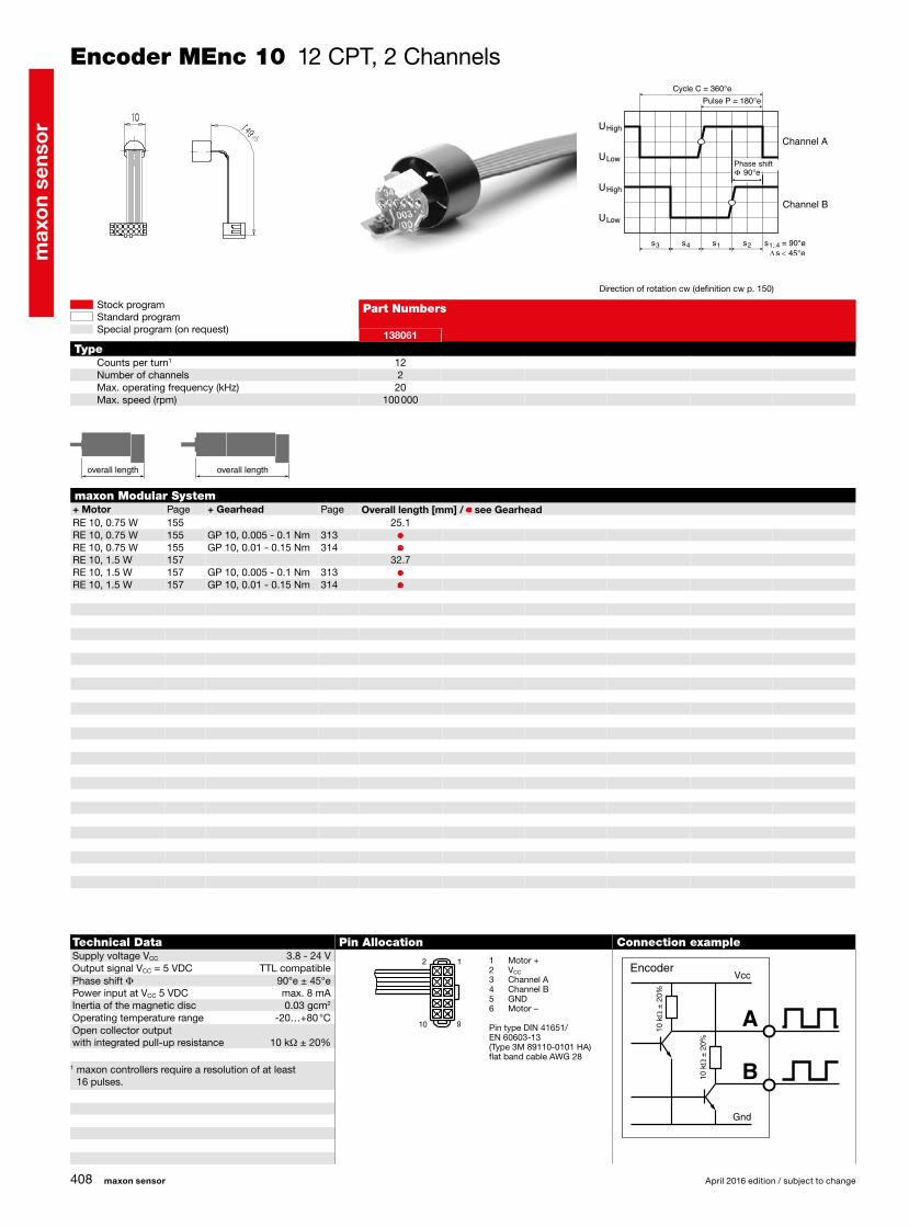
max
on
sens
or
408
RE 10, 0.75 W 155 25.1RE 10, 0.75 W 155 GP 10, 0.005 - 0.1 Nm 313 •RE 10, 0.75 W 155 GP 10, 0.01 - 0.15 Nm 314 •RE 10, 1.5 W 157 32.7RE 10, 1.5 W 157 GP 10, 0.005 - 0.1 Nm 313 •RE 10, 1.5 W 157 GP 10, 0.01 - 0.15 Nm 314 •
2 1
910
138061
122
20100 000
s∆ 45°e<s2 s = 90°e1..4s1s4s3
90°e
10 k
Ω ±
20%
10 k
Ω ±
20%
maxon sensor April 2016 edition / subject to change
Stock programStandard programSpecial program (on request)
Encoder MEnc 10 12 CPT, 2 Channels
maxon Modular System+ Motor Page + Gearhead Page Overall length [mm] / • see Gearhead
Part Numbers
TypeCounts per turn1
Number of channelsMax. operating frequency (kHz)Max. speed (rpm)
Direction of rotation cw (definition cw p. 150)
Technical Data Pin Allocation Connection exampleSupply voltage VCC 3.8 - 24 VOutput signal VCC = 5 VDC TTL compatiblePhase shift Φ 90°e ± 45°ePower input at VCC 5 VDC max. 8 mAInertia of the magnetic disc 0.03 gcm2
Operating temperature range -20…+80 °COpen collector output with integrated pull-up resistance 10 kW ± 20%
1 maxon controllers require a resolution of at least 16 pulses.
1 Motor +2 VCC
3 Channel A4 Channel B5 GND6 Motor –
Pin type DIN 41651/EN 60603-13(Type 3M 89110-0101 HA)flat band cable AWG 28
EncoderVcc
Gnd
overall length overall length
Channel A
Channel B
Cycle C = 360°e
Pulse P = 180°e
Phase shift

max
on
sens
or
409
RE 13, 0.75 W 160/161 27.0/29.4RE 13, 0.75 W 161 GP 13, 0.05 - 0.15 Nm 316 •RE 13, 0.75 W 161 GP 13, 0.2 - 0.35 Nm 317 •RE 13, 2 W 164/165 39.2/41.6RE 13, 2 W 165 GP 13, 0.05 - 0.15 Nm 316 •RE 13, 2 W 165 GP 13, 0.2 - 0.35 Nm 317 •RE 13, 1.5 W 168/169 30.3/32.7RE 13, 1.5 W 169 GP 13, 0.05 - 0.15 Nm 316 •RE 13, 1.5 W 169 GP 13, 0.2 - 0.35 Nm 317 •RE 13, 3 W 172/173 42.5/44.9RE 13, 3 W 173 GP 13, 0.05 - 0.15 Nm 316 •RE 13, 3 W 173 GP 13, 0.2 - 0.35 Nm 317 •RE 16, 3.2 W 176 46.5RE 16, 3.2 W 176 GP 16, 0.1 - 0.6 Nm 323/324 •RE 16, 3.2 W 176 GP 16 S 365/366 •RE 16, 4.5 W 178 49.7RE 16, 4.5 W 178 GP 16, 0.1 - 0.6 Nm 323/324 •RE 16, 4.5 W 178 GP 16 S 365/366 •A-max 16 194/196 33.5A-max 16 194/196 GS 16, 0.01 - 0.03 Nm 319/320 •A-max 16 194/196 GS 16, 0.06 - 0.1 Nm 321/322 •A-max 16 194/196 GP 16, 0.1 - 0.3 Nm 323 •A-max 16 194/196 GP 16 S 365/366 •A-max 19 198/200 36.4/39.0A-max 19 198/200 GP 19, 0.1 - 0.3 Nm 325 •A-max 19 198/200 GP 22, 0.5 - 2.0 Nm 329/331 •A-max 19 198/200 GS 24, 0.1 Nm 335 •A-max 19 198/200 GP 22 S 368/369 •
2 1
910
110778
162
2075 000
s∆ 45°e<s2 s = 90°e1..4s1s4s3
90°e
10 k
Ω ±
20%
10 k
Ω ±
20%
April 2016 edition / subject to change maxon sensor
Stock programStandard programSpecial program (on request)
Encoder MEnc 13 16 CPT, 2 Channels
maxon Modular System+ Motor Page + Gearhead Page Overall length [mm] / • see Gearhead
Part Numbers
TypeCounts per turnNumber of channelsMax. operating frequency (kHz)Max. speed (rpm)
Direction of rotation cw (definition cw p. 150)
Technical Data Pin Allocation Connection exampleSupply voltage VCC 3.8 - 24 VOutput signal VCC = 5 VDC TTL compatiblePhase shift Φ 90°e ± 45°ePower input at VCC 5 VDC max. 8 mAInertia of the magnetic disc 0.07 gcm2
Operating temperature range -20…+80 °COpen collector output with integrated pull-up resistance 10 kW ± 20%
1 Motor +2 VCC
3 Channel A4 Channel B5 GND6 Motor –
Pin typeDIN 41651/EN 60603-13(Type 3M 89110-0101 HA)flat band cable AWG 28
EncoderVcc
Gnd
overall length overall length
Channel A
Channel B
Cycle C = 360°e
Pulse P = 180°e
Phase shift

max
on
sens
or
410
A-max 22 202/204 39.0A-max 22 202/204 GP 22, 0.1 - 0.6 Nm 327/328 •A-max 22 202/204 GP 22, 0.5 - 2.0 Nm 329/331 •A-max 22 202/204 GS 24, 0.1 Nm 335 •A-max 22 202/204 GP 22 S 368/369 •A-max 26 206-212 51.8A-max 26 206-212 GP 26, 0.75 - 4.5 Nm 336 •A-max 26 206-212 GS 30, 0.07 - 0.2 Nm 337 •A-max 26 206-212 GP 32, 0.75 - 4.5 Nm 338 •A-max 26 206-212 GP 32, 0.75 - 6.0 Nm 339 •A-max 26 206-212 GS 38, 0.1 - 0.6 Nm 348 •A-max 26 206-212 GP 32 S 370-372 •
2 1
910
110778
162
2075 000
s∆ 45°e<s2 s = 90°e1..4s1s4s3
90°e
10 k
Ω ±
20%
10 k
Ω ±
20%
maxon sensor April 2016 edition / subject to change
Stock programStandard programSpecial program (on request)
Encoder MEnc 13 16 CPT, 2 Channels
maxon Modular System+ Motor Page + Gearhead Page Overall length [mm] / • see Gearhead
Part Numbers
TypeCounts per turnNumber of channelsMax. operating frequency (kHz)Max. speed (rpm)
Direction of rotation cw (definition cw p. 150)
Technical Data Pin Allocation Connection exampleSupply voltage VCC 3.8 - 24 VOutput signal VCC = 5 VDC TTL compatiblePhase shift Φ 90°e ± 45°ePower input at VCC 5 VDC max. 8 mAInertia of the magnetic disc 0.07 gcm2
Operating temperature range -20…+80 °COpen collector output with integrated pull-up resistance 10 kW ± 20%
1 Motor +2 VCC
3 Channel A4 Channel B5 GND6 Motor –
Pin typeDIN 41651/EN 60603-13(Type 3M 89110-0101 HA)flat band cable AWG 28
EncoderVcc
Gnd
Channel A
Channel B
Cycle C = 360°e
Pulse P = 180°e
Phase shift
overall length overall length

max
on
sens
or
411
RE 25 179/181 76.8RE 25 179/181 GP 26, 0.75 - 2.0 Nm 336 •RE 25 179/181 GP 32, 0.75 - 4.5 Nm 338/339 •RE 25 179/181 GP 32, 0.75 - 6.0 Nm 342 •RE 25 179/181 GP 32, 1.0 - 4.5 Nm 347 •RE 25 179/181 GP 32 S 370-372 •RE 25, 20 W 180 65.3RE 25, 20 W 180 GP 22, 0.5 Nm 329 •RE 25, 20 W 180 GP 26, 0.75 - 2.0 Nm 336 •RE 25, 20 W 180 GP 32, 0.75 - 4.5 Nm 338/339 •RE 25, 20 W 180 GP 32, 0.75 - 6.0 Nm 342 •RE 25, 20 W 180 GP 32, 1.0 - 4.5 Nm 347 •RE 25, 20 W 180 GP 32 S 370-372 •RE 35, 90 W 184 89.1RE 35, 90 W 184 GP 32, 0.75 - 6.0 Nm 338-344 •RE 35, 90 W 184 GP 32, 8 Nm 345 •RE 35, 90 W 184 GP 42, 3.0 - 15 Nm 349 •RE 35, 90 W 184 GP 32 S 370-372 •
118909 118910
3 4
April 2016 edition / subject to change maxon sensor
Stock programStandard programSpecial program (on request)
DC Tacho DCT 22 0.52 Volt
maxon Modular System+ Motor Page + Gearhead Page Overall length [mm] / • see Gearhead
Part Numbers
TypeShaft diameter (mm)
Technical Data Connection exampleOutput voltage per 1000 rpm 0.52 V Max. current 10 mATerminal resistance tacho 37.7 W Tolerance of the output voltage ± 15 %Typical peak to peak ripple ≤ 6 % Rotor inertia (tacho only) < 3 gcm²Ripple frequency per turn 14 Resonance frequency with motors on p. 179 – 181 > 2 kHzLinear voltage tolerance, 500 to 5000 rpm ± 0.2 % with motors on p. 184 > 4.5 kHzLinear voltage tolerance with 10 kΩ load resistance ± 0.7 % Temperature range -20 ... +65 °CPolarity error ± 0.1 %Temperature coefficient of EMF (magnet) -0.02 % /°C Option: Pigtails in place of solder terminals.Temperature coefficient of coil resistance +0.4 % /°C
Important Information• Tacho with moving coil, maxon system.• Tacho with precious metal commutation.• To establish total inertia add motor and
tacho inertias.• With the output shaft turning CW as seen from
the mounting surface, the tacho output voltage will be positive at the + terminal.
• A high impedance load is recommended at tacho terminals.
• The tacho current should be kept low.• The indicated resonance frequency refers to the
motor-tacho rotor system.
Ripple = x 100 (%)
T
180 Ω
Resonance frequency Motor winding-Tacho winding fR ≥ 4 kHz
1 kΩ
UAC
0.1 µF
UDC
overall length overall length

max
on
sens
or
412
EC 32, 80 W 251 80.1EC 32, 80 W 251 GP 32, 0.75 - 6.0 Nm 338-344 •EC 32, 80 W 251 GP 32 S 370-372 •EC 40, 170 W 252 107.2EC 40, 170 W 252 GP 42, 3.0 - 15 Nm 349 •EC 40, 170 W 252 GP 52, 4.0 - 30 Nm 354 •EC 45, 150 W 253 111.2EC 45, 150 W 253 GP 42, 3.0 - 15 Nm 349 •EC 45, 150 W 253 GP 52, 4.0 - 30 Nm 354 •EC 45, 250 W 254 144.0EC 45, 250 W 254 GP 42, 3.0 - 15 Nm 349 •EC 45, 250 W 254 GP 52, 4.0 - 30 Nm 354 •EC 45, 250 W 254 GP 62, 8.0 - 50 Nm 356 •EC 60, 400 W 255 177.3EC 60, 400 W 255 GP 81, 20 - 120 Nm 357 •
166488 133405 268912 199287
4 6 6 610 000 10 000 10 000 10 000
maxon sensor April 2016 edition / subject to change
Stock programStandard programSpecial program (on request)
Resolver Res 26 10 Volt
maxon Modular System+ Motor Page + Gearhead Page Overall length [mm] / • see Gearhead
Part Numbers
TypeShaft diameter (mm)Max. speed (rpm)
Output voltage as a function of the rotor angle after demodulati-on of the input frequency.
overall length overall length
360°m
SIN
COS
Resolv
er
roto
r
SIN
COS
UPrimary Secondary
Rotor-angle
Prim GND
Prim+
cos−
cos+
sin−sin+
Technical Data Pin AllocationInput voltage 10 V peak, 10 kHzTransmission ratio 0.5Electrical error ± 10 minutesRotor inertia 6 gcm2
Weight 40 gOperating temperature range -55 ... +155°C
EC 32/EC 40 EC 45/EC 60Prim + red/white whitePrim GND yellow/white browncos + red greensin + yellow yellowcos – schwarz greysin – blue pink