mb series hvac equipment 1 vertical package … · of a solid state adjustable current motor...
TRANSCRIPT

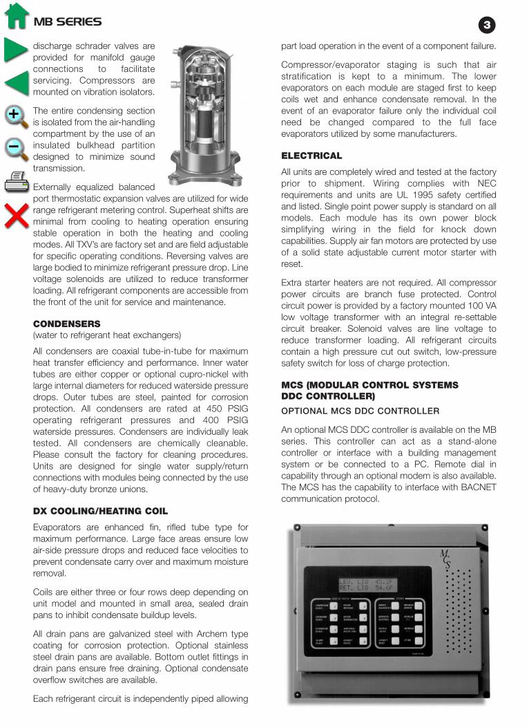
discharge schrader valves areprovided for manifold gaugeconnections to facilitateservicing. Compressors aremounted on vibration isolators.
The entire condensing sectionis isolated from the air-handlingcompartment by the use of aninsulated bulkhead partitiondesigned to minimize soundtransmission.
Externally equalized balancedport thermostatic expansion valves are utilized for widerange refrigerant metering control. Superheat shifts areminimal from cooling to heating operation ensuringstable operation in both the heating and coolingmodes. All TXV’s are factory set and are field adjustablefor specific operating conditions. Reversing valves arelarge bodied to minimize refrigerant pressure drop. Linevoltage solenoids are utilized to reduce transformerloading. All refrigerant components are accessible fromthe front of the unit for service and maintenance.
CONDENSERS(water to refrigerant heat exchangers)
All condensers are coaxial tube-in-tube for maximumheat transfer efficiency and performance. Inner watertubes are either copper or optional cupro-nickel withlarge internal diameters for reduced waterside pressuredrops. Outer tubes are steel, painted for corrosionprotection. All condensers are rated at 450 PSIGoperating refrigerant pressures and 400 PSIGwaterside pressures. Condensers are individually leaktested. All condensers are chemically cleanable.Please consult the factory for cleaning procedures.Units are designed for single water supply/returnconnections with modules being connected by the useof heavy-duty bronze unions.
DX COOLING/HEATING COIL
Evaporators are enhanced fin, rifled tube type formaximum performance. Large face areas ensure lowair-side pressure drops and reduced face velocities toprevent condensate carry over and maximum moistureremoval.
Coils are either three or four rows deep depending onunit model and mounted in small area, sealed drainpans to inhibit condensate buildup levels.
All drain pans are galvanized steel with Archem typecoating for corrosion protection. Optional stainlesssteel drain pans are available. Bottom outlet fittings indrain pans ensure free draining. Optional condensateoverflow switches are available.
Each refrigerant circuit is independently piped allowing
part load operation in the event of a component failure.
Compressor/evaporator staging is such that airstratification is kept to a minimum. The lowerevaporators on each module are staged first to keepcoils wet and enhance condensate removal. In theevent of an evaporator failure only the individual coilneed be changed compared to the full faceevaporators utilized by some manufacturers.
ELECTRICAL
All units are completely wired and tested at the factoryprior to shipment. Wiring complies with NECrequirements and units are UL 1995 safety certifiedand listed. Single point power supply is standard on allmodels. Each module has its own power blocksimplifying wiring in the field for knock downcapabilities. Supply air fan motors are protected by useof a solid state adjustable current motor starter withreset.
Extra starter heaters are not required. All compressorpower circuits are branch fuse protected. Controlcircuit power is provided by a factory mounted 100 VAlow voltage transformer with an integral re-settablecircuit breaker. Solenoid valves are line voltage toreduce transformer loading. All refrigerant circuitscontain a high pressure cut out switch, low-pressuresafety switch for loss of charge protection.
MCS (MODULAR CONTROL SYSTEMSDDC CONTROLLER)
OPTIONAL MCS DDC CONTROLLER
An optional MCS DDC controller is available on the MBseries. This controller can act as a stand-alonecontroller or interface with a building managementsystem or be connected to a PC. Remote dial incapability through an optional modem is also available.The MCS has the capability to interface with BACNETcommunication protocol.
MB SERIES 3
CommercialWater Source andGeothermal ProductsE
NE
RG
Y W
ISE
CO
MM
ER
CIA
L P
RO
DU
CT
S
FHP MANUFACTURING601 N.W. 65th CourtFort Lauderdale, FL 33309(954) 776-5471(800) 776-5529 Faxwww.fhp-mfg.com
LARGE VERTICALMODELS
6-60 TONS
SMALL VERTICALMODELS
1/2 - 5 TONS
ROOFTOPMODELS
4 - 35 TONS
LARGE HORIZONTALMODELS
6 - 20 TONS
SMALL HORIZONTALMODELS
1/2 - 5 TONS
CONSOLEMODELS
3/4 - 11/2 TONS
PRODUCT OFFERING• Vertical Units ............................................................................................................................1/2 - 60 Tons• Horizontal Units .......................................................................................................................1/2 - 20 Tons• Console Units .........................................................................................................................3/4 - 11/2 Tons• Rooftop Units............................................................................................................................4 - 35 Tons• Water to Water Chillers / Boilers................................................................................................3 - 35 Tons• Split Systems...........................................................................................................................1/2 - 30 Tons• Variable Air Volume ...................................................................................................................6 - 60 Tons
FACTORY INSTALLED OPTIONS• Hot Gas Reheat ( Dehumidification ) • 100% Outside / Make up Air Units• Water-side Economizer • Cupronickel Water Coil• Heat Recovery ( Desuperheater ) • Custom Options Available Upon Request
SOFTWAREOur Engineering Application Data Software ( EAD ) is customized for the professional HVAC designer.Professional HVAC designers will find this software to be an instrumental tool for equipment selection. OurEAD Software is available for HVAC designers via our web site at www.fhp-mfg.com free of charge.
MB SERIES
FHP brings to the market a first in large capacity modular reverse cycleunits. The many features and energy efficiency of the MB Series makethem the ideal choice for either new construction or retrofit projects.
UNIT FEATURES
Modular Construction• Separate modules (VH series) will pass
through a 36" wide standard door• No breaking of refrigerant lines required• Water connections are heavy-duty bronze
bodied unions• Single power point connection
State of the art MCS control system• Optional Microprocessor based DDC
controller allows multiple configurations forspecific applications strategies
• LCD display of operating status and faultconditions in plain English
Reverse Cycle Heat Pump Operation• Optional reverse cycle heating• Takes full advantage of building diversity
Energy Efficiency• High efficiency in the cooling mode• Economical operation in heating with reverse cycle operation• Economizer operation reduces compressor operating hours increases
system efficiency• Individual units can be monitored for actual electrical usage by tenants
Variable Air Volume capability• Units can be fitted with VFD for additional energy savings• Increased operational flexibility
Quiet Operation• Scroll compressors for efficient quiet operation• Heavy duty structural components• Multi-density coated glass fiber insulation
Reliability• Units are fully assembled and tested at the factory to ensure smooth
assembly and start up in the field• No reliance on central plant equipment for building climate control• Multiple refrigerant circuits provide redundancy in the event of
component failure
100 % Outside air capability • Hot gas reheat for humidity control
Hot Gas Bypass• Allows operation under a wide variety of conditions• Provides protection against coil freezing
Energy Wise HVAC Equipment
FHP MANUFACTURING601 N.W. 65th CourtFort Lauderdale, FL 33309(954) 776-5471 • (800) 776-5529 Faxwww.fhp-mfg.com
MO
DU
LE
-AIR
E
MB
SERIES
MB
SERIES
HVA
CEQ
UIP
MEN
TH
VA
CEQ
UIP
MEN
T
VE
RT
ICA
L P
AC
KA
GE
UN
ITS

All components are easily accessible for generalmaintenance. Motors are open drip proof NEMA T-Frame E high efficiency EPACT rated with sealed ballbearings.
Optional factory installed variable frequency drives areavailable for variable air volume systems. The drivesare located in the fan module and may be controlled bythe MCS+ controller. A static pressure sensor is fieldinstalled in the supply duct plenum dictating motorspeed based on an increase or decrease in the supplyduct static pressure. VFD’s are factory programmedper job specific design criteria.
All drives are NEMA 4/12 enclosed with an integralkeypad for program adjustments. Removable accesspanels allow drive adjustments during motor operation.Constant power line reactors are also furnished witheach drive for power supply filtration. Please refer tothe Engineering Application Manual for VAV SelfContained Units for further details.
AVAILABLE OPTIONS
• Proof of fluid flow - factory installed differentialpressure switch
• Entering/leaving fluid temperature sensors.
• Factory installed freeze protection sensor.
• Control algorithm options - space/return aircontrol, discharge air with space/return air resetcontrol, VAV control. (Only available with optionalMCS controller.)
• Water-side economizer.
• Hot gas reheat on constant volume units with orwithout 100% outside air introduction.
• Bolt on hot water heating coils, one or two rows.
• Hot gas bypass for extended capacity operationand to prevent coil freezing at low load conditions.
TESTING
All completed units are leak checked, evacuated andfactory charged with R-22. Units are 100% run testedprior to shipment.
PERFORMANCE
For unit performance under specific conditions pleasecontact you FHP Manufacturing representative.
TYPICAL APPLICATIONS
CONSTANT VOLUME AIRFLOW
MB units are ideally suited to air condition large spacesin offices, and shops providing a total climate controlsystem. The units may be applied on a floor by floor
basis or serve a specific area. Unit control isaccomplished by sensing the space or return airtemperature and staging the unit based on the controlset point.
VARIABLE AIR VOLUME
MB units are available with a factory installed variablefrequency drive package for modulating the airflow inresponse to changes in the system duct staticpressure. VAV units have the ability to controltemperatures in areas of different loading such as theinterior and exterior zones of a building. Only thevolume of air that is required to satisfy the space loadis delivered providing significant savings in energy.Typically the system is designed to provide supply airat a constant temperature through the control ofdischarge air temperature. VAV terminals in the spacemodulate open or closed as the load varies increasingor reducing the airflow to satisfy the demand.Temperature reset based on return air temperature isalso available.
DEHUMIDIFICATION
Indoor air quality is a major concern in the design andoperation of today’s buildings. Humidity levels, if notproperly controlled, can play a major role in thedevelopment of fungal growth which is a major causeof the problem. Controlling the space temperaturealone will not assure proper humidity control. To bringthe humidity to an acceptable level requires cooling theair to a relatively low temperature, which can result inuncomfortable conditions within the space. The air,after dehumidification, needs to be reheated to avoidthis problem. Typically electric heat has been applied todo this but is probably the most expensive optionadding significantly to operating costs. An alternativewould be to use hot water if it is available. Again thisrepresents an additional operating cost. Additional hotwater piping will be needed, increasing initial costs. MBunits offer a factory installed hot gas reheat option thatuses the hot refrigerant gas to reheat the air. All of theheat of rejection is not used to reheat the air so thereis a net cooling effect but not enough to createuncomfortable conditions within the occupied space.Hot gas reheat operation is controlled through spacehumidity levels so only operates when needed.
Further information on MB units for specificapplications is available by contacting your local FHPrepresentative.
MB SERIES 5
The controller is capable of monitoring and controllingtemperatures, static pressure (VAV applications),humidity, fluid flow and airflow as required and whenordered with the appropriate sensors.
The standard unit controller is configured for constantvolume, return air control. Optional control strategies areavailable, for example, humidity/reheat control andvariable air volume discharge air temperature control withreturn air reset. All safety inputs are monitored and alarmsignals can be generated. The controller willautomatically restart the machine following a non-criticalalarm condition, not taking the unit off line unless thesame alarm has occurred twice within an adjustable timeperiod. Nuisance shut down of the unit is avoided whilestill providing protection against possible equipmentfailure. A record of faults and time of occurrence is keptin the controller to facilitate trouble shooting and servicingof the unit. A systems time clock is standard on all MCScontrollers enabling programming for daily operations.
All necessary sensors are factory provided, field installedfor application specific control strategy. The controller isconveniently located on the unit for easy reading andprogramming. A 2 line 16 character LCD displays alltemperature, pressure and control functions in easy toread English. Battery back up is standard to prevent lossof operating parameters during powerinterruptions/losses. A four layered printed circuit boardprotects the microprocessor from power surges or fasttransients across or over the lines. Please refer to the unitcontroller manual for further details
REVERSE CYCLE OPERATION
All MB series units are capable of operating in the reversecycle heat pump mode for efficient, cost effectiveheating. The MB series is the only self-contained heatpump unit in its class. This feature allows the designer totake full advantage of building diversity, transferringexcess heat from areas with a net cooling load to areasrequiring heating providing a truly energy efficient system.
HOT WATER COIL
Bolt on one or two row hot water coils for hydronicpreheat are available as a field installed option. Pleaseconsult factory with requirements for coil design andselection.
ECONOMIZER/FILTER BANK MODULE
Factory installed water-side economizer coils areavailable on all MB series units. The economizer packageconsists of full-face area multi-row copper tube,aluminum fin coils designed for low water-side pressuredrops. A 3-way motorized ball valve is included in thepackage for water flow control. The valve includes amanual clutch option for field over-ride capability while anoptional minimum positioner for the valve is also
available. The economizer may be controlled through theoptional MCS controller which senses entering fluidtemperature to the unit and opens the valve to allow flowthrough the economizer coil and condenser in series. Innormal operation, flow is through the condenser only.The set point is adjustable between 45 ºF and 70 ºF in thecooling mode. A heating economizer cycle is alsoavailable for heating utilizing high temperature loop fluidor high temperature fluid from a heat exchanger that is ona hot water hydronic loop. The package has a 400 PSIGdesign working pressure and is pressure tested for leaksat the factory.
FILTERS
All MB series units come with standard 4 inch 30%efficiency pleated filters. Optional 65% 4 inch pleatedfilters are available. Filters are removable from the sidesof the frames through filter access panels. Throw awayconstruction filters should be field installed to protect themain filters during the construction period.
FAN MODULE
MB units contain either one or two forward curved high-pressure class II fan assemblies depending on the modelsize. The fans are double width, double inlet weldedassemblies statically and dynamically balanced. The fanmodule is isolated from the main module by the use ofrubertex gaskets providing excellent vibration isolationand quiet operation. The modules are bolted togetherwith 1/2 inch diameter bolts and locking nuts. Each fan ispowered by it’s own motor and drive assembly. Motorsare mounted on individual motor platforms for stableoperation and belt tension adjustment. All assembliesinclude 150,000-hour re-greaseable pillow blockbearings with large diameter solid steel shafts for hightorque/speed operation. Drive packages comprisemultiple belt, fixed pitch blower pulleys and motorsheaves sized for specific application requirements ofCFM, external static pressures, and motor horsepower.
MB SERIES4
DESIGN FEATURES:
Unit Construction
The FHP MB series is available in two basicconfigurations:
VH CONFIGURATION
The VH design concept is to provide a unit that willfacilitate on site handling and can be installed in locationsdifficult to access. All units can be broken down intoseparate modules that can pass through a 36" widestandard door or service elevator. No refrigerant pipingrequires disconnection, maintaining circuit integrity.Water piping connections are made with the use ofheavy-duty bronze-bodied unions so no welding orbrazing is required in the field. Single supply and returnconnection to the unit are standard. This creative designallows the installer to transport and locate the modules inthe equipment room without the use of heavy-dutycranes or lifts. Building penetrations or interior wallpenetrations are not normally required on retrofit jobswhere space is at a premium. The 30 ton module can beeasily broken down into 3 separate modules - the fanmodule, main heating/cooling module and theeconomizer/filter bank. The 40 through 60 ton units canbe broken into 6 separate modules, two each aspreviously mentioned. Very few competitive equipmentmanufacturers have this capability.
VL CONFIGURATION
The VL is designed for those applications where there isa restriction in the height of the unit. In this model theblower is dropped into the main coil section reducing theunits overall height and increasing unit depth. Unit sizesMB480 through MB720 can be split into two sections fortransportation and access into the plant room.
FLEXIBILITY
The FHP MB series is available in cooling only or withreverse cycle heating with either constant or variable airvolume discharge to provide a highly efficient operatingsystem. Water-side economizer packages are availableto take advantage of free cooling. Optional field installedhot water coils provide preheating or heating. Hot gasbypass allows the unit to operate under a wide variationof conditions and the hot gas reheat option provides ameans of controlling humidity, a major concern in theinterior environment of a building.
UNIT PERFORMANCE
The units are available in four sizes from nominal 30through 60 tons.
Performance is with nominal CFM and rated inaccordance with ARI 320 conditions. Performancenumbers are gross.
CABINET, CASING AND FRAME
For heavy-duty structural support an internal angle ironframework is utilized. The angle iron members areattached using 1/2 inch bolts and locking nuts for easeof disassembly and re-assembly. The base-panassembly is constructed of 14 gauge galvanized steel.Exterior panels are made of 18 gauge, G90 galvanizedsteel providing protection against corrosion. All panelsare insulated with 1/2 inch thick dual density Neoprenebacked fiberglass insulation for thermal and acousticperformance. Insulation meets the erosion requirementsof UL 181. Base rails are provided to assist rigging theunit on site. All components are located for ease ofinspection and service. Major components are out of theunits air stream to allow maintenance while the unit is inoperation. Service access is through the removal ofaccess panels located on the unit.
MAIN COOLING / HEATING MODULE
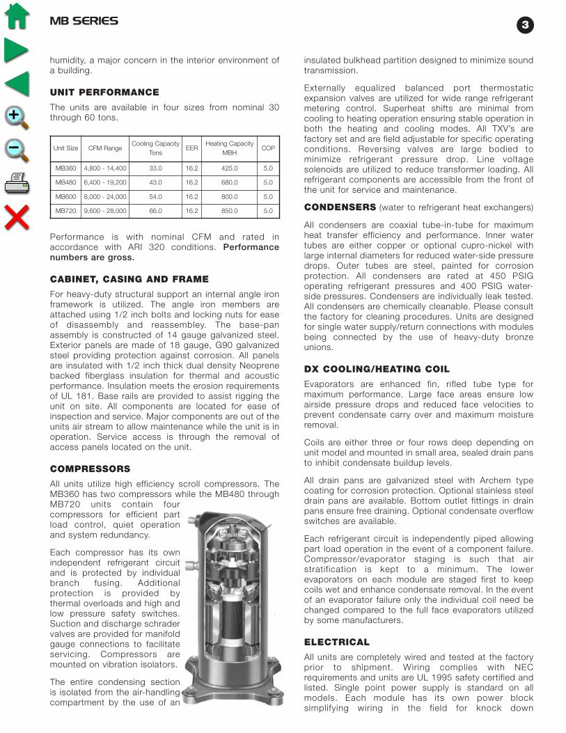
COMPRESSORS
All units utilize high efficiency scroll compressors. TheMB360 has two compressors while the MB480 throughMB720 units contain four compressors for efficient partload control, quiet operation and system redundancy.Each compressor has its own independent refrigerantcircuit and is protected by individual branch fusing.Additional protection is provided by thermal overloadsand high and low pressure safety switches. Suction and
MB SERIES2
VH Configuration
Unit Size CFM RangeCooling Capacity
TonsEER
Heating Capacity
MBH COP
MB360 4,800 - 14,400 33.0 16.2 425.0 5.0
MB480 6,400 - 19,200 43.0 16.2 680.0 5.0
MB600 8,000 - 24,000 54.0 16.2 800.0 5.0
MB720 9,600 - 28,000 66.0 16.2 850.0 5.0
discharge schrader valves areprovided for manifold gaugeconnections to facilitateservicing. Compressors aremounted on vibration isolators.
The entire condensing sectionis isolated from the air-handlingcompartment by the use of aninsulated bulkhead partitiondesigned to minimize soundtransmission.
Externally equalized balancedport thermostatic expansion valves are utilized for widerange refrigerant metering control. Superheat shifts areminimal from cooling to heating operation ensuringstable operation in both the heating and coolingmodes. All TXV’s are factory set and are field adjustablefor specific operating conditions. Reversing valves arelarge bodied to minimize refrigerant pressure drop. Linevoltage solenoids are utilized to reduce transformerloading. All refrigerant components are accessible fromthe front of the unit for service and maintenance.
CONDENSERS(water to refrigerant heat exchangers)
All condensers are coaxial tube-in-tube for maximumheat transfer efficiency and performance. Inner watertubes are either copper or optional cupro-nickel withlarge internal diameters for reduced waterside pressuredrops. Outer tubes are steel, painted for corrosionprotection. All condensers are rated at 450 PSIGoperating refrigerant pressures and 400 PSIGwaterside pressures. Condensers are individually leaktested. All condensers are chemically cleanable.Please consult the factory for cleaning procedures.Units are designed for single water supply/returnconnections with modules being connected by the useof heavy-duty bronze unions.
DX COOLING/HEATING COIL
Evaporators are enhanced fin, rifled tube type formaximum performance. Large face areas ensure lowair-side pressure drops and reduced face velocities toprevent condensate carry over and maximum moistureremoval.
Coils are either three or four rows deep depending onunit model and mounted in small area, sealed drainpans to inhibit condensate buildup levels.
All drain pans are galvanized steel with Archem typecoating for corrosion protection. Optional stainlesssteel drain pans are available. Bottom outlet fittings indrain pans ensure free draining. Optional condensateoverflow switches are available.
Each refrigerant circuit is independently piped allowing
part load operation in the event of a component failure.
Compressor/evaporator staging is such that airstratification is kept to a minimum. The lowerevaporators on each module are staged first to keepcoils wet and enhance condensate removal. In theevent of an evaporator failure only the individual coilneed be changed compared to the full faceevaporators utilized by some manufacturers.
ELECTRICAL
All units are completely wired and tested at the factoryprior to shipment. Wiring complies with NECrequirements and units are UL 1995 safety certifiedand listed. Single point power supply is standard on allmodels. Each module has its own power blocksimplifying wiring in the field for knock downcapabilities. Supply air fan motors are protected by useof a solid state adjustable current motor starter withreset.
Extra starter heaters are not required. All compressorpower circuits are branch fuse protected. Controlcircuit power is provided by a factory mounted 100 VAlow voltage transformer with an integral re-settablecircuit breaker. Solenoid valves are line voltage toreduce transformer loading. All refrigerant circuitscontain a high pressure cut out switch, low-pressuresafety switch for loss of charge protection.
MCS (MODULAR CONTROL SYSTEMSDDC CONTROLLER)
OPTIONAL MCS DDC CONTROLLER
An optional MCS DDC controller is available on the MBseries. This controller can act as a stand-alonecontroller or interface with a building managementsystem or be connected to a PC. Remote dial incapability through an optional modem is also available.The MCS has the capability to interface with BACNETcommunication protocol.
MB SERIES 3
CommercialWater Source andGeothermal ProductsE
NE
RG
Y W
ISE
CO
MM
ER
CIA
L P
RO
DU
CT
S
FHP MANUFACTURING601 N.W. 65th CourtFort Lauderdale, FL 33309(954) 776-5471(800) 776-5529 Faxwww.fhp-mfg.com
LARGE VERTICALMODELS
6-60 TONS
SMALL VERTICALMODELS
1/2 - 5 TONS
ROOFTOPMODELS
4 - 35 TONS
LARGE HORIZONTALMODELS
6 - 20 TONS
SMALL HORIZONTALMODELS
1/2 - 5 TONS
CONSOLEMODELS
3/4 - 11/2 TONS
PRODUCT OFFERING• Vertical Units ............................................................................................................................1/2 - 60 Tons• Horizontal Units .......................................................................................................................1/2 - 20 Tons• Console Units .........................................................................................................................3/4 - 11/2 Tons• Rooftop Units............................................................................................................................4 - 35 Tons• Water to Water Chillers / Boilers................................................................................................3 - 35 Tons• Split Systems...........................................................................................................................1/2 - 30 Tons• Variable Air Volume ...................................................................................................................6 - 60 Tons
FACTORY INSTALLED OPTIONS• Hot Gas Reheat ( Dehumidification ) • 100% Outside / Make up Air Units• Water-side Economizer • Cupronickel Water Coil• Heat Recovery ( Desuperheater ) • Custom Options Available Upon Request
SOFTWAREOur Engineering Application Data Software ( EAD ) is customized for the professional HVAC designer.Professional HVAC designers will find this software to be an instrumental tool for equipment selection. OurEAD Software is available for HVAC designers via our web site at www.fhp-mfg.com free of charge.
MB SERIES
FHP brings to the market a first in large capacity modular reverse cycleunits. The many features and energy efficiency of the MB Series makethem the ideal choice for either new construction or retrofit projects.
UNIT FEATURES
Modular Construction• Separate modules (VH series) will pass
through a 36" wide standard door• No breaking of refrigerant lines required• Water connections are heavy-duty bronze
bodied unions• Single power point connection
State of the art MCS control system• Optional Microprocessor based DDC
controller allows multiple configurations forspecific applications strategies
• LCD display of operating status and faultconditions in plain English
Reverse Cycle Heat Pump Operation• Optional reverse cycle heating• Takes full advantage of building diversity
Energy Efficiency• High efficiency in the cooling mode• Economical operation in heating with reverse cycle operation• Economizer operation reduces compressor operating hours increases
system efficiency• Individual units can be monitored for actual electrical usage by tenants
Variable Air Volume capability• Units can be fitted with VFD for additional energy savings• Increased operational flexibility
Quiet Operation• Scroll compressors for efficient quiet operation• Heavy duty structural components• Multi-density coated glass fiber insulation
Reliability• Units are fully assembled and tested at the factory to ensure smooth
assembly and start up in the field• No reliance on central plant equipment for building climate control• Multiple refrigerant circuits provide redundancy in the event of
component failure
100 % Outside air capability • Hot gas reheat for humidity control
Hot Gas Bypass• Allows operation under a wide variety of conditions• Provides protection against coil freezing
Energy Wise HVAC Equipment
FHP MANUFACTURING601 N.W. 65th CourtFort Lauderdale, FL 33309(954) 776-5471 • (800) 776-5529 Faxwww.fhp-mfg.com
MO
DU
LE
-AIR
E
MB
SERIES
MB
SERIES
HVA
CEQ
UIP
MEN
TH
VA
CEQ
UIP
MEN
T
VE
RT
ICA
L P
AC
KA
GE
UN
ITS

All components are easily accessible for generalmaintenance. Motors are open drip proof NEMA T-Frame E high efficiency EPACT rated with sealed ballbearings.
Optional factory installed variable frequency drives areavailable for variable air volume systems. The drivesare located in the fan module and may be controlled bythe MCS+ controller. A static pressure sensor is fieldinstalled in the supply duct plenum dictating motorspeed based on an increase or decrease in the supplyduct static pressure. VFD’s are factory programmedper job specific design criteria.
All drives are NEMA 4/12 enclosed with an integralkeypad for program adjustments. Removable accesspanels allow drive adjustments during motor operation.Constant power line reactors are also furnished witheach drive for power supply filtration. Please refer tothe Engineering Application Manual for VAV SelfContained Units for further details.
AVAILABLE OPTIONS
• Proof of fluid flow - factory installed differentialpressure switch
• Entering/leaving fluid temperature sensors.
• Factory installed freeze protection sensor.
• Control algorithm options - space/return aircontrol, discharge air with space/return air resetcontrol, VAV control. (Only available with optionalMCS controller.)
• Water-side economizer.
• Hot gas reheat on constant volume units with orwithout 100% outside air introduction.
• Bolt on hot water heating coils, one or two rows.
• Hot gas bypass for extended capacity operationand to prevent coil freezing at low load conditions.
TESTING
All completed units are leak checked, evacuated andfactory charged with R-22. Units are 100% run testedprior to shipment.
PERFORMANCE
For unit performance under specific conditions pleasecontact you FHP Manufacturing representative.
TYPICAL APPLICATIONS
CONSTANT VOLUME AIRFLOW
MB units are ideally suited to air condition large spacesin offices, and shops providing a total climate controlsystem. The units may be applied on a floor by floor
basis or serve a specific area. Unit control isaccomplished by sensing the space or return airtemperature and staging the unit based on the controlset point.
VARIABLE AIR VOLUME
MB units are available with a factory installed variablefrequency drive package for modulating the airflow inresponse to changes in the system duct staticpressure. VAV units have the ability to controltemperatures in areas of different loading such as theinterior and exterior zones of a building. Only thevolume of air that is required to satisfy the space loadis delivered providing significant savings in energy.Typically the system is designed to provide supply airat a constant temperature through the control ofdischarge air temperature. VAV terminals in the spacemodulate open or closed as the load varies increasingor reducing the airflow to satisfy the demand.Temperature reset based on return air temperature isalso available.
DEHUMIDIFICATION
Indoor air quality is a major concern in the design andoperation of today’s buildings. Humidity levels, if notproperly controlled, can play a major role in thedevelopment of fungal growth which is a major causeof the problem. Controlling the space temperaturealone will not assure proper humidity control. To bringthe humidity to an acceptable level requires cooling theair to a relatively low temperature, which can result inuncomfortable conditions within the space. The air,after dehumidification, needs to be reheated to avoidthis problem. Typically electric heat has been applied todo this but is probably the most expensive optionadding significantly to operating costs. An alternativewould be to use hot water if it is available. Again thisrepresents an additional operating cost. Additional hotwater piping will be needed, increasing initial costs. MBunits offer a factory installed hot gas reheat option thatuses the hot refrigerant gas to reheat the air. All of theheat of rejection is not used to reheat the air so thereis a net cooling effect but not enough to createuncomfortable conditions within the occupied space.Hot gas reheat operation is controlled through spacehumidity levels so only operates when needed.
Further information on MB units for specificapplications is available by contacting your local FHPrepresentative.
MB SERIES 5
The controller is capable of monitoring and controllingtemperatures, static pressure (VAV applications),humidity, fluid flow and airflow as required and whenordered with the appropriate sensors.
The standard unit controller is configured for constantvolume, return air control. Optional control strategies areavailable, for example, humidity/reheat control andvariable air volume discharge air temperature control withreturn air reset. All safety inputs are monitored and alarmsignals can be generated. The controller willautomatically restart the machine following a non-criticalalarm condition, not taking the unit off line unless thesame alarm has occurred twice within an adjustable timeperiod. Nuisance shut down of the unit is avoided whilestill providing protection against possible equipmentfailure. A record of faults and time of occurrence is keptin the controller to facilitate trouble shooting and servicingof the unit. A systems time clock is standard on all MCScontrollers enabling programming for daily operations.
All necessary sensors are factory provided, field installedfor application specific control strategy. The controller isconveniently located on the unit for easy reading andprogramming. A 2 line 16 character LCD displays alltemperature, pressure and control functions in easy toread English. Battery back up is standard to prevent lossof operating parameters during powerinterruptions/losses. A four layered printed circuit boardprotects the microprocessor from power surges or fasttransients across or over the lines. Please refer to the unitcontroller manual for further details
REVERSE CYCLE OPERATION
All MB series units are capable of operating in the reversecycle heat pump mode for efficient, cost effectiveheating. The MB series is the only self-contained heatpump unit in its class. This feature allows the designer totake full advantage of building diversity, transferringexcess heat from areas with a net cooling load to areasrequiring heating providing a truly energy efficient system.
HOT WATER COIL
Bolt on one or two row hot water coils for hydronicpreheat are available as a field installed option. Pleaseconsult factory with requirements for coil design andselection.
ECONOMIZER/FILTER BANK MODULE
Factory installed water-side economizer coils areavailable on all MB series units. The economizer packageconsists of full-face area multi-row copper tube,aluminum fin coils designed for low water-side pressuredrops. A 3-way motorized ball valve is included in thepackage for water flow control. The valve includes amanual clutch option for field over-ride capability while anoptional minimum positioner for the valve is also
available. The economizer may be controlled through theoptional MCS controller which senses entering fluidtemperature to the unit and opens the valve to allow flowthrough the economizer coil and condenser in series. Innormal operation, flow is through the condenser only.The set point is adjustable between 45 ºF and 70 ºF in thecooling mode. A heating economizer cycle is alsoavailable for heating utilizing high temperature loop fluidor high temperature fluid from a heat exchanger that is ona hot water hydronic loop. The package has a 400 PSIGdesign working pressure and is pressure tested for leaksat the factory.
FILTERS
All MB series units come with standard 4 inch 30%efficiency pleated filters. Optional 65% 4 inch pleatedfilters are available. Filters are removable from the sidesof the frames through filter access panels. Throw awayconstruction filters should be field installed to protect themain filters during the construction period.
FAN MODULE
MB units contain either one or two forward curved high-pressure class II fan assemblies depending on the modelsize. The fans are double width, double inlet weldedassemblies statically and dynamically balanced. The fanmodule is isolated from the main module by the use ofrubertex gaskets providing excellent vibration isolationand quiet operation. The modules are bolted togetherwith 1/2 inch diameter bolts and locking nuts. Each fan ispowered by it’s own motor and drive assembly. Motorsare mounted on individual motor platforms for stableoperation and belt tension adjustment. All assembliesinclude 150,000-hour re-greaseable pillow blockbearings with large diameter solid steel shafts for hightorque/speed operation. Drive packages comprisemultiple belt, fixed pitch blower pulleys and motorsheaves sized for specific application requirements ofCFM, external static pressures, and motor horsepower.
MB SERIES4
DESIGN FEATURES:
Unit Construction
The FHP MB series is available in two basicconfigurations:
VH CONFIGURATION
The VH design concept is to provide a unit that willfacilitate on site handling and can be installed in locationsdifficult to access. All units can be broken down intoseparate modules that can pass through a 36" widestandard door or service elevator. No refrigerant pipingrequires disconnection, maintaining circuit integrity.Water piping connections are made with the use ofheavy-duty bronze-bodied unions so no welding orbrazing is required in the field. Single supply and returnconnection to the unit are standard. This creative designallows the installer to transport and locate the modules inthe equipment room without the use of heavy-dutycranes or lifts. Building penetrations or interior wallpenetrations are not normally required on retrofit jobswhere space is at a premium. The 30 ton module can beeasily broken down into 3 separate modules - the fanmodule, main heating/cooling module and theeconomizer/filter bank. The 40 through 60 ton units canbe broken into 6 separate modules, two each aspreviously mentioned. Very few competitive equipmentmanufacturers have this capability.
VL CONFIGURATION
The VL is designed for those applications where there isa restriction in the height of the unit. In this model theblower is dropped into the main coil section reducing theunits overall height and increasing unit depth. Unit sizesMB480 through MB720 can be split into two sections fortransportation and access into the plant room.
FLEXIBILITY
The FHP MB series is available in cooling only or withreverse cycle heating with either constant or variable airvolume discharge to provide a highly efficient operatingsystem. Water-side economizer packages are availableto take advantage of free cooling. Optional field installedhot water coils provide preheating or heating. Hot gasbypass allows the unit to operate under a wide variationof conditions and the hot gas reheat option provides ameans of controlling humidity, a major concern in theinterior environment of a building.
UNIT PERFORMANCE
The units are available in four sizes from nominal 30through 60 tons.
Performance is with nominal CFM and rated inaccordance with ARI 320 conditions. Performancenumbers are gross.
CABINET, CASING AND FRAME
For heavy-duty structural support an internal angle ironframework is utilized. The angle iron members areattached using 1/2 inch bolts and locking nuts for easeof disassembly and re-assembly. The base-panassembly is constructed of 14 gauge galvanized steel.Exterior panels are made of 18 gauge, G90 galvanizedsteel providing protection against corrosion. All panelsare insulated with 1/2 inch thick dual density Neoprenebacked fiberglass insulation for thermal and acousticperformance. Insulation meets the erosion requirementsof UL 181. Base rails are provided to assist rigging theunit on site. All components are located for ease ofinspection and service. Major components are out of theunits air stream to allow maintenance while the unit is inoperation. Service access is through the removal ofaccess panels located on the unit.
MAIN COOLING / HEATING MODULE
COMPRESSORS
All units utilize high efficiency scroll compressors. TheMB360 has two compressors while the MB480 throughMB720 units contain four compressors for efficient partload control, quiet operation and system redundancy.Each compressor has its own independent refrigerantcircuit and is protected by individual branch fusing.Additional protection is provided by thermal overloadsand high and low pressure safety switches. Suction and
MB SERIES2
VH Configuration
Unit Size CFM RangeCooling Capacity
TonsEER
Heating Capacity
MBH COP
MB360 4,800 - 14,400 33.0 16.2 425.0 5.0
MB480 6,400 - 19,200 43.0 16.2 680.0 5.0
MB600 8,000 - 24,000 54.0 16.2 800.0 5.0
MB720 9,600 - 28,000 66.0 16.2 850.0 5.0

discharge schrader valves areprovided for manifold gaugeconnections to facilitateservicing. Compressors aremounted on vibration isolators.
The entire condensing sectionis isolated from the air-handlingcompartment by the use of aninsulated bulkhead partitiondesigned to minimize soundtransmission.
Externally equalized balancedport thermostatic expansion valves are utilized for widerange refrigerant metering control. Superheat shifts areminimal from cooling to heating operation ensuringstable operation in both the heating and coolingmodes. All TXV’s are factory set and are field adjustablefor specific operating conditions. Reversing valves arelarge bodied to minimize refrigerant pressure drop. Linevoltage solenoids are utilized to reduce transformerloading. All refrigerant components are accessible fromthe front of the unit for service and maintenance.
CONDENSERS(water to refrigerant heat exchangers)
All condensers are coaxial tube-in-tube for maximumheat transfer efficiency and performance. Inner watertubes are either copper or optional cupro-nickel withlarge internal diameters for reduced waterside pressuredrops. Outer tubes are steel, painted for corrosionprotection. All condensers are rated at 450 PSIGoperating refrigerant pressures and 400 PSIGwaterside pressures. Condensers are individually leaktested. All condensers are chemically cleanable.Please consult the factory for cleaning procedures.Units are designed for single water supply/returnconnections with modules being connected by the useof heavy-duty bronze unions.
DX COOLING/HEATING COIL
Evaporators are enhanced fin, rifled tube type formaximum performance. Large face areas ensure lowair-side pressure drops and reduced face velocities toprevent condensate carry over and maximum moistureremoval.
Coils are either three or four rows deep depending onunit model and mounted in small area, sealed drainpans to inhibit condensate buildup levels.
All drain pans are galvanized steel with Archem typecoating for corrosion protection. Optional stainlesssteel drain pans are available. Bottom outlet fittings indrain pans ensure free draining. Optional condensateoverflow switches are available.
Each refrigerant circuit is independently piped allowing
part load operation in the event of a component failure.
Compressor/evaporator staging is such that airstratification is kept to a minimum. The lowerevaporators on each module are staged first to keepcoils wet and enhance condensate removal. In theevent of an evaporator failure only the individual coilneed be changed compared to the full faceevaporators utilized by some manufacturers.
ELECTRICAL
All units are completely wired and tested at the factoryprior to shipment. Wiring complies with NECrequirements and units are UL 1995 safety certifiedand listed. Single point power supply is standard on allmodels. Each module has its own power blocksimplifying wiring in the field for knock downcapabilities. Supply air fan motors are protected by useof a solid state adjustable current motor starter withreset.
Extra starter heaters are not required. All compressorpower circuits are branch fuse protected. Controlcircuit power is provided by a factory mounted 100 VAlow voltage transformer with an integral re-settablecircuit breaker. Solenoid valves are line voltage toreduce transformer loading. All refrigerant circuitscontain a high pressure cut out switch, low-pressuresafety switch for loss of charge protection.
MCS (MODULAR CONTROL SYSTEMSDDC CONTROLLER)
OPTIONAL MCS DDC CONTROLLER
An optional MCS DDC controller is available on the MBseries. This controller can act as a stand-alonecontroller or interface with a building managementsystem or be connected to a PC. Remote dial incapability through an optional modem is also available.The MCS has the capability to interface with BACNETcommunication protocol.
MB SERIES 3
CommercialWater Source andGeothermal ProductsE
NE
RG
Y W
ISE
CO
MM
ER
CIA
L P
RO
DU
CT
S
FHP MANUFACTURING601 N.W. 65th CourtFort Lauderdale, FL 33309(954) 776-5471(800) 776-5529 Faxwww.fhp-mfg.com
LARGE VERTICALMODELS
6-60 TONS
SMALL VERTICALMODELS
1/2 - 5 TONS
ROOFTOPMODELS
4 - 35 TONS
LARGE HORIZONTALMODELS
6 - 20 TONS
SMALL HORIZONTALMODELS
1/2 - 5 TONS
CONSOLEMODELS
3/4 - 11/2 TONS
PRODUCT OFFERING• Vertical Units ............................................................................................................................1/2 - 60 Tons• Horizontal Units .......................................................................................................................1/2 - 20 Tons• Console Units .........................................................................................................................3/4 - 11/2 Tons• Rooftop Units............................................................................................................................4 - 35 Tons• Water to Water Chillers / Boilers................................................................................................3 - 35 Tons• Split Systems...........................................................................................................................1/2 - 30 Tons• Variable Air Volume ...................................................................................................................6 - 60 Tons
FACTORY INSTALLED OPTIONS• Hot Gas Reheat ( Dehumidification ) • 100% Outside / Make up Air Units• Water-side Economizer • Cupronickel Water Coil• Heat Recovery ( Desuperheater ) • Custom Options Available Upon Request
SOFTWAREOur Engineering Application Data Software ( EAD ) is customized for the professional HVAC designer.Professional HVAC designers will find this software to be an instrumental tool for equipment selection. OurEAD Software is available for HVAC designers via our web site at www.fhp-mfg.com free of charge.
MB SERIES
FHP brings to the market a first in large capacity modular reverse cycleunits. The many features and energy efficiency of the MB Series makethem the ideal choice for either new construction or retrofit projects.
UNIT FEATURES
Modular Construction• Separate modules (VH series) will pass
through a 36" wide standard door• No breaking of refrigerant lines required• Water connections are heavy-duty bronze
bodied unions• Single power point connection
State of the art MCS control system• Optional Microprocessor based DDC
controller allows multiple configurations forspecific applications strategies
• LCD display of operating status and faultconditions in plain English
Reverse Cycle Heat Pump Operation• Optional reverse cycle heating• Takes full advantage of building diversity
Energy Efficiency• High efficiency in the cooling mode• Economical operation in heating with reverse cycle operation• Economizer operation reduces compressor operating hours increases
system efficiency• Individual units can be monitored for actual electrical usage by tenants
Variable Air Volume capability• Units can be fitted with VFD for additional energy savings• Increased operational flexibility
Quiet Operation• Scroll compressors for efficient quiet operation• Heavy duty structural components• Multi-density coated glass fiber insulation
Reliability• Units are fully assembled and tested at the factory to ensure smooth
assembly and start up in the field• No reliance on central plant equipment for building climate control• Multiple refrigerant circuits provide redundancy in the event of
component failure
100 % Outside air capability • Hot gas reheat for humidity control
Hot Gas Bypass• Allows operation under a wide variety of conditions• Provides protection against coil freezing
Energy Wise HVAC Equipment
FHP MANUFACTURING601 N.W. 65th CourtFort Lauderdale, FL 33309(954) 776-5471 • (800) 776-5529 Faxwww.fhp-mfg.com
MO
DU
LE
-AIR
E
MB
SERIES
MB
SERIES
HVA
CEQ
UIP
MEN
TH
VA
CEQ
UIP
MEN
T
VE
RT
ICA
L P
AC
KA
GE
UN
ITS

MB
SE
RIE
S
MA
NU
AL
MB SERIES ( APPLICATION )
Energy Wise HVAC Equipment
FHP MANUFACTURING601 N.W. 65th CourtFort Lauderdale, FL 33309(954) 776-5471 • (800) 776-5529 Faxwww.fhp-mfg.com
APPLIC
ATIO
NA
PPLIC
ATIO
N
TABLE OF CONTENTS
Unit Features ....................................................................................................1Design Features................................................................................................2Reverse Cycle Operation ..................................................................................5Economizer / Filter Bank Module......................................................................5Blowers ............................................................................................................5Available Options..............................................................................................5Selection Procedure .........................................................................................7Specification Data Sheets.................................................................................9Physical Data Specifications ...........................................................................13Water-side Economizer Performance..............................................................14Correction Factors..........................................................................................14Hot Water Coil Capacity .................................................................................15Pressure Drop Tables .....................................................................................16Blower Performance.......................................................................................17Drive Selection Table ......................................................................................18Shipping Weights ...........................................................................................19Physical Dimensions.......................................................................................20Electrical Specifications ..................................................................................24Wiring Diagrams .............................................................................................25Guide Specifications.......................................................................................28
FHP brings to the market a first in large capacity modular reverse cycle units.Their many features and energy efficiency make them theideal choice for either new construction or retrofitprojects.
UNIT FEATURES
Modular Construction• Separate modules (VH series) will
pass through a 36" wide standarddoor
• No breaking of refrigerant linesrequired
• Water connections are heavy-dutybronze bodied unions
• Single power point connection
State of the art MCS ControlSystem• Optional Microprocessor based
DDC controller allows multipleconfigurations for specificapplications strategies
• LCD display of operating status and faultconditions in plain English

Reverse Cycle Heat Pump Operation• Optional reverse cycle heating
• Takes full advantage of building diversity
Energy Efficiency• High efficiency in the cooling mode
• Economical operation in heating with reverse cycleoperation
• Economizer operation reduces compressoroperating hours increases system efficiency
• Individual units can be monitored for actualelectrical usage by tenants
Variable Air Volume Capability• Units can be fitted with VFD for additional energy
savings
• Increased operational flexibility
Quiet Operation• Scroll compressors for efficient quiet operation
• Heavy duty structural components
• Multi density coated glass fiber insulation
Reliability• Units are fully assembled and tested at the factory
to ensure smooth assembly and start up in the field
• No reliance on central plant equipment for buildingclimate control
• Multiple refrigerant circuits provide redundancy inthe event of component failure
100% Outside Air Capability • Hot gas reheat for humidity control
Hot Gas Bypass• Allows operation under a wide variety of conditions
• Provides protection against coil freezing
DESIGN FEATURES:
Unit ConstructionThe FHP MB series is available in two basicconfigurations:
VH CONFIGURATIONThe VH design concept is to provide a unit that willfacilitate on site handling and can be installed inlocations difficult to access. All units can be brokendown into separate modules that can pass through a36" wide standard door or service elevator. Norefrigerant piping requires disconnection, maintainingcircuit integrity. Water piping connections are made
with the use of heavy-duty bronze-bodied unions so nowelding or brazing is required in the field. Single supplyand return connection to the unit are standard. Thiscreative design allows the installer to transport andlocate the modules in the equipment room without theuse of heavy-duty cranes or lifts. Building penetrationsor interior wall penetrations are not normally requiredon retrofit jobs where space is at a premium. The 30ton module can be easily broken down into 3 separatemodules - the fan module, main heating/coolingmodule and the economizer/filter bank. The 40 through60 ton units can be broken into 6 separate modules,two each as previously mentioned. Very fewcompetitive equipment manufacturers have thiscapability.
VL CONFIGURATIONThe VL is designed for those applications where thereis a restriction in the height of the unit. In this model theblower is dropped into the main coil section reducingthe units overall height and increasing unit depth. Unitsizes MB480 through MB720 can be split into twosections for transportation and access into the plantroom.
Please see unit drawings on pages 20 through 23 forunit dimensions.
FLEXIBILITY
The FHP MB series is available in cooling only or withreverse cycle heating with either constant or variableair volume discharge to provide a highly efficientoperating system. Water-side economizer packagesare available to take advantage of free cooling.Optional field installed hot water coils providepreheating or heating. Hot gas bypass allows the unitto operate under a wide variation of conditions and thehot gas reheat option provides a means of controlling
MB SERIES2
VH Configuration
humidity, a major concern in the interior environment ofa building.
UNIT PERFORMANCE
The units are available in four sizes from nominal 30through 60 tons.
Performance is with nominal CFM and rated inaccordance with ARI 320 conditions. Performancenumbers are gross.
CABINET, CASING AND FRAME
For heavy-duty structural support an internal angle ironframework is utilized. The angle iron members areattached using 1/2 inch bolts and locking nuts for easeof disassembly and reassembley. The base-panassembly is constructed of 14 gauge galvanized steel.Exterior panels are made of 18 gauge, G90 galvanizedsteel providing protection against corrosion. All panelsare insulated with 1/2 inch thick dual density Neoprenebacked fiberglass insulation for thermal and acousticperformance. Insulation meets the erosion requirementsof UL 181. Base rails are provided to assist rigging theunit on site. All components are located for ease ofinspection and service. Major components are out of theunits air stream to allow maintenance while the unit is inoperation. Service access is through the removal ofaccess panels located on the unit.
COMPRESSORS
All units utilize high efficiency scroll compressors. TheMB360 has two compressors while the MB480 throughMB720 units contain fourcompressors for efficient partload control, quiet operationand system redundancy.
Each compressor has its ownindependent refrigerant circuitand is protected by individualbranch fusing. Additionalprotection is provided bythermal overloads and high andlow pressure safety switches.Suction and discharge schradervalves are provided for manifoldgauge connections to facilitateservicing. Compressors aremounted on vibration isolators.
The entire condensing sectionis isolated from the air-handlingcompartment by the use of an
insulated bulkhead partition designed to minimize soundtransmission.
Externally equalized balanced port thermostaticexpansion valves are utilized for wide range refrigerantmetering control. Superheat shifts are minimal fromcooling to heating operation ensuring stable operation inboth the heating and cooling modes. All TXV’s arefactory set and are field adjustable for specific operatingconditions. Reversing valves are large bodied tominimize refrigerant pressure drop. Line voltagesolenoids are utilized to reduce transformer loading. Allrefrigerant components are accessible from the front ofthe unit for service and maintenance.
CONDENSERS (water to refrigerant heat exchangers)
All condensers are coaxial tube-in-tube for maximumheat transfer efficiency and performance. Inner watertubes are either copper or optional cupro-nickel withlarge internal diameters for reduced water-side pressuredrops. Outer tubes are steel, painted for corrosionprotection. All condensers are rated at 450 PSIGoperating refrigerant pressures and 400 PSIG water-side pressures. Condensers are individually leak tested.All condensers are chemically cleanable. Please consultthe factory for cleaning procedures. Units are designedfor single water supply/return connections with modulesbeing connected by the use of heavy-duty bronzeunions.
DX COOLING/HEATING COIL
Evaporators are enhanced fin, rifled tube type formaximum performance. Large face areas ensure lowairside pressure drops and reduced face velocities toprevent condensate carry over and maximum moistureremoval.
Coils are either three or four rows deep depending onunit model and mounted in small area, sealed drain pansto inhibit condensate buildup levels.
All drain pans are galvanized steel with Archem typecoating for corrosion protection. Optional stainless steeldrain pans are available. Bottom outlet fittings in drainpans ensure free draining. Optional condensate overflowswitches are available.
Each refrigerant circuit is independently piped allowingpart load operation in the event of a component failure.Compressor/evaporator staging is such that airstratification is kept to a minimum. The lowerevaporators on each module are staged first to keepcoils wet and enhance condensate removal. In the eventof an evaporator failure only the individual coil need bechanged compared to the full face evaporators utilizedby some manufacturers.
ELECTRICAL
All units are completely wired and tested at the factoryprior to shipment. Wiring complies with NECrequirements and units are UL 1995 safety certified andlisted. Single point power supply is standard on allmodels. Each module has its own power blocksimplifying wiring in the field for knock down
3MB SERIES
Unit Size CFM RangeCooling Capacity
TonsEER
Heating CapacityMBH
COP
MB360 4,800 - 14,400 33.0 16.2 425.0 5.0
MB480 6,400 - 19,200 43.0 16.2 680.0 5.0
MB600 8,000 - 24,000 54.0 16.2 800.0 5.0
MB720 9,600 - 28,000 66.0 16.2 850.0 5.0

capabilities. Supply air fan motors are protected by useof a solid state adjustable current motor starter withreset.
Extra starter heaters are not required. All compressorpower circuits are branch fuse protected. Control circuitpower is provided by a factory mounted 100 VA lowvoltage transformer with an integral resettable circuitbreaker. Solenoid valves are line voltage to reducetransformer loading.
SAFETY DEVICES AND THE UPMCONTROLLER
Each MB unit is factory provided with a Unit ProtectionModule (UPM) that controls compressor operation andmonitors the safety controls that protect the unit.
Safety controls include the following:
• High pressure switches located in the refrigerantdischarge lines. One per refrigeration circuit.
• Low pressure switches for loss of charge protectionlocated in the unit refrigerant suction lines. One perrefrigeration circuit.
• Optional freeze protection sensor located on theleaving side of the water coil prevents unit operationbelow 35ºF. Freeze terminals must be jumpedtogether if the freeze sensor is not installed.
• Optional Condensate overflow protection sensorlocated in the drain pan(s) of the unit and wired tothe UPM board.
The UPM includes the following features:
• ANTI-SHORT CYCLE TIMER – 5 minute delay onbreak timer to prevent compressor short cycling.
• RANDOM START – Each controller has a uniquerandom start delay ranging between 270 through330 seconds.
• LOW PRESSURE BYPASS TIMER - The lowpressure switch is bypassed for 90 seconds aftercompressor start-up to prevent nuisance lowpressure lockouts during cold start-up in the heatingmode.
• BROWNOUT/SURGE/POWER INTERRUPTIONPROTECTION – a 20 millisecond window ismonitored for the above condition. Should any ofthese conditions be detected, the 5-minute delay onbreak timer and the random start timer delay areinitiated.
• MALFUNCTION OUTPUT – The controller has a setof wet contacts for remote fault indication.
• TEST SERVICE PIN – A jumper pin is provided toreduce all time delay settings to 5 seconds duringtroubleshooting or verification of unit operation.Note that operation of the unit in test mode can leadto accelerated wear and premature failure of theunit.
• L.E.D. FAULT INDICATION – Two L.E.D. indicators
are provided as follows:
• GREEN: Power L.E.D. indicates 18 – 30 VACpresent at the board.
• RED: Fault indictor with blink codes as follows:
One per Dual Circuits (UPM-II)
•• ONE BLINK 1st Stage high pressure lockout
•• TWO BLINKS 1st Stage low pressure lockout
•• THREE BLINKS 2nd Stage high pressure lockout
•• FOUR BLINKS 2nd Stage low pressure lockout
•• FIVE BLINKS Freeze Protection lockout
•• SIX BLINKS Condensate overflow lockout
• INTELLIGENT RESET - If a fault condition isinitiated the 5 minute delay on break time periodand the random start timer are initiated and the unitwill restart after these delays expire. During thisperiod the fault LED will indicate the cause of thefault. If the fault condition still exists or reoccursbefore the thermostat is satisfied, the unit will gointo a hard lockout and requires a manual lockoutreset.
• LOCKOUT RESET - A hard lockout can be reset byturning the unit thermostat off and then back on orby shutting off unit power at the circuit breaker.
NOTE: The blower motor will remain active during alockout condition.
MCS (MODULAR CONTROL SYSTEMSDDC CONTROLLER)
OPTIONAL MCS DDC CONTROLLER
An optional MCS DDC controller is available on the MBseries. This controller can act as a stand-alonecontroller or interface with a building managementsystem or be connected to a PC. Remote dial incapability through an optional modem is also available.The MCS has the capability to interface with BACNETcommunication protocol.
MB SERIES4

The controller is capable of monitoring and controllingtemperatures, static pressure (VAV applications),humidity, fluid flow and airflow as required and whenordered with the appropriate sensors.
The standard unit controller is configured for constantvolume, return air control. Optional control strategiesare available, for example, humidity/reheat control andvariable air volume discharge air temperature controlwith return air reset. All safety inputs are monitored andalarm signals can be generated. The controller willautomatically restart the machine following a non-criticalalarm condition, not taking the unit off line unless thesame alarm has occurred twice within an adjustabletime period. Nuisance shut down of the unit is avoidedwhile still providing protection against possibleequipment failure. A record of faults and time ofoccurrence is kept in the controller to facilitate troubleshooting and servicing of the unit. A systems time clockis standard on all MCS controllers enablingprogramming for daily operations.
All necessary sensors are factory provided, fieldinstalled for application specific control strategy. Thecontroller is conveniently located on the unit for easyreading and programming. A 2 line 16 character LCDdisplays all temperature, pressure and control functionsin easy to read English. Battery back up is standard toprevent loss of operating parameters during powerinterruptions/losses. A four layered printed circuit boardprotects the microprocessor from power surges or fasttransients across or over the lines. Please refer to theunit controller manual for further details
REVERSE CYCLE OPERATION
All MB series units are capable of operating in thereverse cycle heat pump mode for efficient, costeffective heating. The MB series is the only self-contained heat pump unit in its class. This feature allowsthe designer to take full advantage of building diversity,transferring excess heat from areas with a net coolingload to areas requiring heating providing a truly energyefficient system.
HOT WATER COIL
An optional one or two row hot water coil is available forhydronic heating. The coil is available either installed inthe filter section (if the economizer option is not ordered)or for external mounting. In both cases piping, valvesand controls are by others.
EECCOONNOOMMIIZZEERR//FFIILLTTEERR BBAANNKK MMOODDUULLEE
Factory installed water-side economizer coils areavailable on all MB series units. The economizerpackage consists of full-face area multi-row coppertube, aluminum fin coils designed for low water-sidepressure drops. A 3-way motorized ball valve is includedin the package for water flow control. The valve includesa manual clutch option for field over-ride capability whilean optional minimum positioner for the valve is alsoavailable. The economizer may be controlled throughthe optional controller which senses entering fluidtemperature to the unit and opens the valve to allowflow through the economizer coil and condenser in
series. In normal operation, flow is through thecondenser only. The set point is adjustable between 45degrees and 70 degrees in the cooling mode. A heatingeconomizer cycle is also available utilizing hightemperature loop fluid or high temperature fluid from aheat exchanger that is on a hot water hydronic loop. Thepackage has a 400 PSIG design working pressure andis pressure tested for leaks at the factory.
FILTERS
All MB series units come with standard 4 inch 30%efficiency pleated filters. Optional 65% 4 inch pleatedfilters are available. Filters are removable from the sidesof the frames through filter access panels. Throw awayconstruction filters should be field installed to protectthe main filters during the construction period.
BBLLOOWWEERRSS
The units contain either one or two forward curved high-pressure class II fan assemblies depending on themodel size. The fans are double width, double inletwelded assemblies statically and dynamically balanced.In the VH Series, the fan module is isolated from themain module by the use of rubertex gaskets providingexcellent vibration isolation and quiet operation. Themodules are bolted together with 1/2 inch diameterbolts and locking nuts. Each fan is powered by it’s ownmotor and drive assembly. Motors are mounted onindividual motor platforms for stable operation and belttension adjustment. All assemblies include 150,000-hour re-greaseable pillow block bearings with largediameter solid steel shafts for high torque/speedoperation. Drive packages comprise multiple belt, fixedpitch blower pulleys and motor sheaves sized forspecific application requirements of CFM, external staticpressures, and motor horsepower. All components areeasily accessible for general maintenance. Motors areopen drip proof NEMA T-Frame E high efficiency EPACTrated with sealed ball bearings.
5MB SERIES

Optional factory installed variable frequency drives areavailable for variable air volume systems. The drives arelocated in the fan section and may be controlled by theoptional MCS controller. A static pressure sensor isfield installed in the supply duct plenum dictating motorspeed based on an increase or decrease in the supplyduct static pressure. VFD’s are factory programmedper job specific design criteria.
All drives are NEMA 4/12 enclosed with an integralkeypad for program adjustments. Removable accesspanels allow drive adjustments during motor operation.Constant power line reactors are also furnished witheach drive for power supply filtration. Please refer tothe Engineering Application Manual for VAV SelfContained Units for further details.
AVAILABLE OPTIONS
• Proof of fluid flow - factory installed differentialpressure switch
• Entering/leaving fluid temperature sensors.
• Factory installed freeze protection sensor.
• Control algorithm options - space/return aircontrol, discharge air with space/return air resetcontrol, VAV control. Only available with optionalMCS controller.
• Water-side economizer.
• Hot gas reheat on constant volume units with orwithout 100% outside air introduction - factoryinstalled with controls for dehumidificationapplications when equipped with optional MCScontroller.
• Hot water heating coils, one or two rows.
• Hot gas bypass for extended capacity operationand to prevent coil freezing at low load conditions.
• *MCS DDC Controller
TESTING
All completed units are leak checked, evacuated andfactory charged with R-22. Units are 100% run testedprior to shipment.
PERFORMANCE
For unit performance under specific conditions pleasecontact you FHP Manufacturing representative.
CONSTANT VOLUME AIRFLOW
MB units are ideally suited to air condition large spacesin offices and shops providing a total climate controlsystem. The units may be applied on a floor by floorbasis or serve a specific area. Unit control isaccomplished by sensing the space or return airtemperature and staging the unit based on the controlset point.
VARIABLE AIR VOLUME
MB units are available with a factory installed variable
frequency drive package for modulating the airflow inresponse to changes in the system duct staticpressure. VAV units have the ability to controltemperatures in areas of different loading such as theinterior and exterior zones of a building. Only thevolume of air that is required to satisfy the space loadis delivered providing significant savings in energy.Typically the system is designed to provide supply air ata constant temperature through the control ofdischarge air temperature. VAV terminals in the spacemodulate open or closed as the load varies increasingor reducing the airflow to satisfy the demand.Temperature reset based on return air temperature isalso available.
DEHUMIDIFICATION
Indoor air quality is a major concern in the design andoperation of today’s buildings. Humidity levels, if notproperly controlled, can play a major role in thedevelopment of fungal growth which is a major causeof the problem. Controlling the space temperaturealone will not assure proper humidity control. To bringthe humidity to an acceptable level requires cooling theair to a relatively low temperature, which can result inuncomfortable conditions within the space. The air,after dehumidification, needs to be reheated to avoidthis problem. Typically electric heat has been applied todo this but is probably the most expensive optionadding significantly to operating costs. An alternativewould be to use hot water if it is available. Again thisrepresents an additional operating cost. Addition hotwater piping will be needed, increasing initial costs.MB units offer a factory installed hot gas reheat optionthat uses the hot refrigerant gas to reheat the air. All ofthe heat of rejection is not used to reheat the air sothere is a net cooling effect but not enough to createuncomfortable conditions within the occupied space.Hot gas reheat operation is controlled through spacehumidity levels and only operates when needed.
MB SERIES6

SELECTION PROCEDURE
The following example is intended to illustrate the selection of an MB unit. For applications outside of the publisheddata sheets please contact your FHP representative.
Requirements
FHP series MB unit is to provide cooling and reverse cycle heating. A water-side economizer coil is to be provided tooperate when the loop water temperature falls below 60°F. Electrical service is 460/3/60
Design conditions:Airflow .............................................................................................................................................................16,000 CFMExternal static pressure.................................................................................................................................................2.0"Entering air temperature .........................................................................................................................................85/73°FFlow rate ..............................................................................................................................................................120 GPM
CoolingCooling capacity total ..................................................................................................................................540,000 BTUHCooling capacity sensible ............................................................................................................................405,000 BTUHEntering/Leaving water temperature .......................................................................................................................85/95°F
Heating Capacity ......................................................................................................................................................400,000 BTUHEntering air temperature...............................................................................................................................................70°FEntering water temperature..........................................................................................................................................65°F
Unit selectionSelect the unit with the airflow and capacity closest to the specified requirements. From the unit specification sheet thiswould be a model MB480.
Cooling performanceFrom the MB480 specification data sheet:AT 16,000 CFM and condenser water flow rate of 120 GPMTotal capacity...............................................................................................................................................556,941 BTUHSensible Capacity ........................................................................................................................................409,908 BTUHWatts input.....................................................................................................................................................32,841 WattsEER..............................................................................................................................................................................17.0Heat rejection ..............................................................................................................................................668,995 BTUH
Calculate:Water temperature rise.......................................................668,995 .........................................................................11.2°F
500 x 120
Leaving water temperature ..............................................85 + 11.2 .........................................................................96.2°FFrom the water-side component pressure drop tableWater pressure drop ................................................................................................................................................15.0 ft.
Heating performanceFrom the unit specification data sheet the entering water temperature falls between 60 and 70°F and the unit performancemay be interpolated. Do not extrapolate unit performance.Unit capacity................................................................................................................................................641,037 BTUHWatts input ....................................................................................................................................................38,463 BTUHUnit COP......................................................................................................................................................................4.88Heat of absorption.......................................................................................................................................509,800 BTUHWater temperature drop .....................................................509,800 ...........................................................................8.5°F
500 x 120Leaving water temperature.................................................65 - 8.5..........................................................................56.5°F
Economizer PerformanceFrom the economizer performance sheet, based 80/67°F air and 120 gpm water entering at 45°F.Total capacity...............................................................................................................................................552,000 BTUHSensible Capacity ........................................................................................................................................384,000 BTUHThe performance must be adjusted for specific operating conditions.
7MB SERIES

MB SERIES8
Fluid temperature correction factor: Total capacity .............................................................................................................................................................0.470Sensible capacity .......................................................................................................................................................0.470
Air temperature Correction factor:Total capacity correction at 73°F WB .........................................................................................................................1.090Sensible capacity correction at 85°F DB ....................................................................................................................0.970
Economizer corrected capacity:Total capacity ........................................................552,000 x 0.470 x 1.090 ...............................................282,790 BTUHSensible capacity ..................................................384,000 x 0.470 x 0.970 ...............................................175.065 BTUH
From a psychometric chart the leaving air conditions can be determined.Leaving air DB/WB......................................................................................................................................75.4/68.4°FWater temperature rise....................................................282,790.........................................................................4.7°F
500 x 120
Leaving water temperature..............................................60 + 4.7.......................................................................64.7°F
This is the entering water temperature to the unit condenser (64.7°F)
Water pressure drop through economizer ...........................................................................................................13.1 Ft Total water pressure drop with economizer operating is the sum of condenser and economizerTotal unit water pressure drop .....................................15.0 + 13.1 ...................................................................28.1 Ft
Fan PerformanceDetermine the internal air pressure drop through the unitDX coil (wet) ..........................................................................................................................................................0.47"Economizer coil .....................................................................................................................................................0.26"4" 30% filters (clean)..............................................................................................................................................0.09"Total internal static pressure ..................................................................................................................................0.82"Add external static pressure.................................................................................................................................+ 2.0"
Total static pressure...............................................................................................................................................2.82"From the MB480 fan curve RPM ........................................................................................................................................................................920Motor - each ......................................................................................................................................................7.5 HP.From the drive selection table select drive....................................................................................041-005 two required
Unit Weight VH ConfigurationFrom the table of unit weightsMain section....................................................................................................................................................2,350 lbsFilter section.......................................................................................................................................................620 lbsEconomizer ........................................................................................................................................................400 lbsFan section .....................................................................................................................................................1,300 lbsTotal weight.....................................................................................................................................................4,670 lbs
Unit Electrical DataFrom the table on unit electrical dataCompressor RLA ....................................................................................................................................................19.2Number of compressors ..............................................................................................................................................4Fan RLA ...................................................................................................................................................................9.7Number of motors .......................................................................................................................................................2Minimum circuit ampacity .........................(Largest load x 1.25) + all other loadsAmpacity .....................................................(19.2 x 1.25) + 3 x 19.2 + 2 x 9.7 ....................................................101.0Maximum fuse size ...................................(Largest load x 2.25) + all other loadsFuse size .....................................................(19.2 x 2.25) + 3 x 19.2 + 2 x 9.7 ....................................................120.2Use next smaller fuse size........................................................................................................................................110
Note: Performance data calculated above is gross with no allowance made for fan HP.

WATER FLOW (GPM) PRESS. DROP (FOH)
50.0 6.0
60.0 8.7
70.0 11.8
80.0 15.4
90.0 19.5
100.0 24.1
9MB SERIES
ELECTRICAL SPECIFICATIONS
PERFORMANCE DATA
BLOWER PERFORMANCESee Blower Performance Curves
COOLING HEATING
CONDENSER WATER FLOW
CAPACITY DATAAll performance at 12000 CFM and 90.0 GPMNOTE: All capacities and efficiencies shown are gross values.
MB360 MODULE-AIRE
MECHANICAL SPECIFICATIONS
As a result of continuing research and development, specifications are subject to change without notice.
MODULAR VERTICAL PACKAGE UNITSSPECIFICATION DATA SHEETFHP MANUFACTURING HIGH-EFFICIENCY WATER SOURCE HEAT PUMPS
RATED IN ACCORDANCE WITH ARI 320
COOLING HEATING
CAPACITY EER CAPACITY COP GPM
400000 16.2 425000 5.0 90.0
EnteringWaterTemp.
DryBulb
HeatingCapacity
BTUH
Heat ofAbsorption
BTUH
PowerInputWatts
COP
50°60° 345374 273819 29072 4.8
70° 327592 254684 21368 4.5
80° 306690 232260 21814 4.1
60°60° 396722 319202 22720 5.1
70° 376296 297312 23149 4.8
80° 352287 271653 23632 4.4
70°60° 448070 364586 24468 5.4
70° 425000 339939 24930 5.0
80° 397883 311046 25451 4.6
80°60° 499501 410053 26216 5.6
70° 473783 382645 26711 5.2
80° 443554 350512 27269 4.8
EnteringWaterTemp.
Ent. AirWet Bulb
Temp.
TotalCapacity
BTUH
WattsInput
HeatRejection
BTUH
Sensible Capacity BTUHEnt. Air Dry Bulb ˚F EER
75˚ 80˚ 85˚
50˚
61° 489925 19890 557790 372833 447301 489925 24.6
64° 513676 20331 583046 348786 442789 491075 25.3
67° 537828 20775 608712 321083 419506 484045 25.9
70° 562379 21222 634788 267693 370046 481397 26.5
73° 587331 21672 661275 - 315397 432275 27.1
60˚
61° 455788 20860 526962 346854 416134 455788 21.8
64° 477884 21322 550636 324483 411936 456857 22.4
67° 500353 21788 574694 298711 390275 450318 23
70° 523194 22257 599133 249040 344261 447854 23.5
73° 546406 22728 623956 - 293420 402155 24
70˚
61° 420133 21830 494616 319721 383581 420133 19.2
64° 440501 22314 516636 299100 379712 421119 19.7
67° 461212 22801 539009 275344 359745 415091 20.2
70° 482266 23291 561736 229559 317331 412820 20.7
73° 503663 23785 584818 - 270467 370696 21.2
85˚
61° 364372 23640 445033 277287 332672 364372 15.4
64° 382037 24164 464486 259403 329316 365227 15.8
67° 400000 24692 484249 238800 312000 360000 16.2
70° 418259 25223 504320 199091 275214 358030 16.6
73° 436816 25758 524702 - 234570 321497 17
100˚
61° 311648 25107 397313 237164 284535 311648 12.4
64° 326757 25664 414321 221868 281664 312379 12.7
67° 342120 26224 431596 204246 266854 307908 13
70° 357737 26788 449138 170283 235391 306223 13.4
73° 373609 27356 466948 - 200628 274977 13.7
Units are complete packages containing allrefrigeration components: compressor, reversingvalve, thermal expansion valve metering device andwater-to-refrigerant condenser. Also included aresafety controls: Overload protection for motors, highand low refrigerant pressure switches and a lock-outcontrol circuit.
FHP MANUFACTURING601 N.W. 65th Court
Ft. Lauderdale, FL 33309Phone: (954) 776-5471
Fax: (800) 776-5529www.fhp-mfg.com
ELECTRICALCHARACTERISTICS
ELECTR. SYM.
COMPRESSOREACH
BLOWEREACH MIN.
CIRCUITAMPACITY
FUSE (T/D)HACR
CIRCUITBREAKER RLA LRA NPA HP
208/230-3-60 -3 62.2 376.0See
“Motor Nameplate Data”on Page 24
460-3-60 -4 27.6 178.0
– – – –
– – – –
EVAPORATOR
SQUAREFEET
ROWSDEEP
TUBESIZE
FPI
23.2 4 1/2 12
BLOWERSIZE (EACH)
SHIPWEIGHT
18 x 18 2,866

MB SERIES10
WATER FLOW (GPM) PRESS. DROP (FOH)
80.0 6.7
90.0 8.4
100.0 10.3
110.0 12.6
120.0 15.0
130.0 17.6
ELECTRICAL SPECIFICATIONS
PERFORMANCE DATA
BLOWER PERFORMANCESee Blower Performance Curves
HEATING
CONDENSER WATER FLOW
CAPACITY DATAAll performance at 16000 CFM and 120.0 GPMNOTE: All capacities and efficiencies shown are gross values.
MB480 MODULE-AIRE
MECHANICAL SPECIFICATIONS
As a result of continuing research and development, specifications are subject to change without notice.
MODULAR VERTICAL PACKAGE UNITSSPECIFICATION DATA SHEETFHP MANUFACTURING HIGH-EFFICIENCY WATER SOURCE HEAT PUMPS
RATED IN ACCORDANCE WITH ARI 320
COOLING HEATING
CAPACITY EER CAPACITY COP GPM
510000 16.2 680000 5.0 120.0
EnteringWaterTemp.
DryBulb
HeatingCapacity
BTUH
Heat ofAbsorption
BTUH
PowerInputWatts
COP
50°60° 552599 438110 33555 4.8
70° 524147 407495 34189 4.5
80° 490705 371616 34903 4.1
60°60° 634755 510723 36352 5.1
70° 602074 475699 37038 4.8
80° 563659 434644 37812 4.4
70°60° 716912 583337 39148 5.4
70° 680000 543902 39888 5.0
80° 636613 497673 40721 4.6
80°60° 799201 656084 41945 5.6
70° 758053 612232 42738 5.2
80° 709686 560820 43630 4.8
Units are complete packages containing allrefrigeration components: compressor, reversingvalve, thermal expansion valve metering device andwater-to-refrigerant condenser. Also included aresafety controls: Overload protection for motors, highand low refrigerant pressure switches and a lock-outcontrol circuit.
FHP MANUFACTURING601 N.W. 65th Court
Ft. Lauderdale, FL 33309Phone: (954) 776-5471
Fax: (800) 776-5529www.fhp-mfg.com
ELECTRICALCHARACTERISTICS
ELECTR. SYM.
COMPRESSOREACH
BLOWEREACH MIN.
CIRCUITAMPACITY
FUSE (T/D)HACR
CIRCUITBREAKER RLA LRA NPA HP
208/230-3-60 -3 42.0 239.0See
“Motor Nameplate Data”on Page 24
460-3-60 -4 19.2 125.0
– – – –
– – – –
EVAPORATOR
SQUAREFEET
ROWSDEEP
TUBESIZE
FPI
46.4 3 3/8 12
BLOWERSIZE (EACH)
SHIPWEIGHT
18 x 18 4,846
EnteringWaterTemp.
Ent. AirWet Bulb
Temp.
TotalCapacity
BTUH
WattsInput
HeatRejection
BTUH
Sensible Capacity BTUHEnt. Air Dry Bulb ˚F EER
75˚ 80˚ 85˚
50˚
61° 624654 25360 711182 475362 570309 624654 24.6
64° 654937 25922 743384 444702 564556 626120 25.3
67° 685731 26488 776108 409381 534870 617158 25.9
70° 717034 27058 809355 341308 471808 613781 26.5
73° 748847 27631 843125 - 402131 551151 27.1
60˚
61° 581129 26597 671876 442239 530571 581129 21.8
64° 609302 27186 702061 413716 525219 582493 22.4
67° 637950 27780 732734 380856 497601 574155 23
70° 667072 28377 763895 317526 438933 571014 23.5
73° 696668 28979 795544 - 374111 512748 24
70˚
61° 535669 27833 630636 407644 489066 535669 19.2
64° 561639 28450 658710 381353 484132 536926 19.7
67° 588045 29071 687236 351063 458675 529241 20.2
70° 614889 29697 716214 292687 404597 526345 20.7
73° 642170 30326 745643 - 344845 472637 21.2
85˚
61° 464575 30141 567417 353541 424157 464575 15.4
64° 487097 30810 592220 330739 419878 465665 15.8
67° 509999 31482 617417 304470 397800 458999 16.2
70° 533280 32159 643008 253841 350898 456488 16.6
73° 556941 32841 668995 - 299077 409908 17
100˚
61° 397351 32012 506575 302384 362782 397351 12.4
64° 416615 32721 528260 282881 359122 398284 12.7
67° 436203 33436 550285 260413 340238 392583 13
70° 456115 34155 572651 217111 300124 390435 13.4
73° 476352 34879 595358 - 255801 350595 13.7
COOLING

11
WATER FLOW (GPM) PRESS. DROP (FOH)
110.0 7.3
120.0 8.7
130.0 10.1
140.0 11.7
150.0 13.5
160.0 15.4
ELECTRICAL SPECIFICATIONS
PERFORMANCE DATA
BLOWER PERFORMANCESee Blower Performance Curves
COOLING HEATING
CONDENSER WATER FLOW
CAPACITY DATAAll performance at 20000 CFM and 150.0 GPMNOTE: All capacities and efficiencies shown are gross values.
MB600 MODULE-AIRE
MECHANICAL SPECIFICATIONS
As a result of continuing research and development, specifications are subject to change without notice.
MODULAR VERTICAL PACKAGE UNITSSPECIFICATION DATA SHEETFHP MANUFACTURING HIGH-EFFICIENCY WATER SOURCE HEAT PUMPS
RATED IN ACCORDANCE WITH ARI 320
COOLING HEATING
CAPACITY EER CAPACITY COP GPM
650000 16.2 800000 5.0 150.0
EnteringWaterTemp.
Ent. AirWet Bulb
Temp.
TotalCapacity
BTUH
WattsInput
HeatRejection
BTUH
Sensible Capacity BTUHEnt. Air Dry Bulb ˚F EER
75˚ 80˚ 85˚
50˚
61˚ 796127 32321 906407 605853 726864 796127 24.6
64˚ 834723 33038 947449 566777 719531 797995 25.3
67˚ 873970 33759 989156 521760 681696 786573 25.9
70˚ 913866 34485 1031530 435000 601324 782269 26.5
73˚ 954412 35216 1074570 - 512519 702447 27.1
60˚
61˚ 740699 33898 856358 563672 676258 740699 21.9
64˚ 776608 34649 894832 527317 669436 742437 22.4
67˚ 813122 35406 933927 485434 634235 731810 23.0
70˚ 850240 36167 973644 404714 559458 727806 23.5
73˚ 887963 36934 1013983 - 476836 653541 24.0
70˚
61˚ 682716 35473 803750 519547 623319 682716 19.2
64˚ 715814 36260 839531 486037 617031 684318 19.7
67˚ 749469 37051 875888 447433 584586 674522 20.2
70˚ 783682 37848 912820 373033 515663 670832 20.7
73˚ 818452 38651 950327 - 439509 602381 21.2
85˚
61˚ 592105 38415 723178 450592 540592 592105 15.4
64˚ 620811 39267 754789 421531 535139 593495 15.8
67˚ 650000 40124 786903 388050 507000 585000 16.2
70˚ 679671 40987 819520 323524 447224 581799 16.6
73˚ 709827 41856 852640 - 381177 522433 17.0
100˚
61˚ 506428 40798 645632 385392 462369 506428 12.4
64˚ 530980 41703 673270 360535 457705 507617 12.7
67˚ 555945 42613 701341 331899 433637 500351 13.0
70˚ 581323 43530 729847 276710 382511 497613 13.4
73˚ 607115 44453 758788 - 326021 446837 13.7
Units are complete packages containing allrefrigeration components: compressor, reversingvalve, thermal expansion valve metering device andwater-to-refrigerant condenser. Also included aresafety controls: Overload protection for motors, highand low refrigerant pressure switches and a lock-outcontrol circuit.
FHP MANUFACTURING601 N.W. 65th Court
Ft. Lauderdale, FL 33309Phone: (954) 776-5471
Fax: (800) 776-5529www.fhp-mfg.com
ELECTRICALCHARACTERISTICS
ELECTR. SYM.
COMPRESSOREACH
BLOWEREACH MIN.
CIRCUITAMPACITY
FUSE (T/D)HACR
CIRCUITBREAKER RLA LRA NPA HP
208/230-3-60 -3 47.1 318.0See
“Motor Nameplate Data”on Page 24
460-3-60 -4 22.6 158.0
– – – –
– – – –
EVAPORATOR
SQUAREFEET
ROWSDEEP
TUBESIZE
FPI
46.4 4 1/2 12
BLOWERSIZE (EACH)
SHIPWEIGHT
18 x 18 5,700
EnteringWaterTemp.
DryBulb
HeatingCapacity
BTUH
Heat ofAbsorption
BTUH
PowerInputWatts
COP
50°60° 650116 514910 39627 4.8
70° 616643 478883 40375 4.5
80° 577299 436661 41219 4.1
60°60° 746771 600297 42929 5.1
70° 708322 559081 43740 4.7
80° 663128 510770 44654 4.4
70°60° 843425 685680 46232 5.3
70° 800000 639274 47106 5
80° 748956 584874 48090 4.6
80°60° 940236 771224 49535 5.6
70° 891827 719621 50471 5.2
80° 834925 659122 51525 4.7

MB SERIES12
WATER FLOW (GPM) PRESS. DROP (FOH)
100.0 6.0
120.0 8.7
140.0 11.8
160.0 15.4
180.0 19.5
200.0 24.1
ELECTRICAL SPECIFICATIONS
PERFORMANCE DATA
BLOWER PERFORMANCESee Blower Performance Curves
HEATING
CONDENSER WATER FLOW
CAPACITY DATAAll performance at 24000 CFM and 180.0 GPMNOTE: All capacities and efficiencies shown are gross values.
MB720 MODULE-AIRE
MECHANICAL SPECIFICATIONS
As a result of continuing research and development, specifications are subject to change without notice.
MODULAR VERTICAL PACKAGE UNITSSPECIFICATION DATA SHEETFHP MANUFACTURING HIGH-EFFICIENCY WATER SOURCE HEAT PUMPS
RATED IN ACCORDANCE WITH ARI 320
COOLING HEATING
CAPACITY EER CAPACITY COP GPM
800000 16.2 850000 5.0 180.0
EnteringWaterTemp.
DryBulb
HeatingCapacity
BTUH
Heat ofAbsorption
BTUH
PowerInputWatts
COP
50°60° 690748 547637 41944 4.8
70° 655184 509369 42736 4.5
80° 613381 464520 43629 4.1
60°60° 793444 638404 45439 5.1
70° 752592 594623 46298 4.8
80° 704574 543306 47265 4.4
70°60° 896139 729172 48935 5.4
70° 850000 679878 49860 5.0
80° 795767 622091 50901 4.6
80°60° 999001 820106 52431 5.6
70° 947566 765290 53422 5.2
80° 887107 701025 54538 4.8
Units are complete packages containing allrefrigeration components: compressor, reversingvalve, thermal expansion valve metering device andwater-to-refrigerant condenser. Also included aresafety controls: Overload protection for motors, highand low refrigerant pressure switches and a lock-outcontrol circuit.
FHP MANUFACTURING601 N.W. 65th Court
Ft. Lauderdale, FL 33309Phone: (954) 776-5471
Fax: (800) 776-5529www.fhp-mfg.com
ELECTRICALCHARACTERISTICS
ELECTR. SYM.
COMPRESSOREACH
BLOWEREACH MIN.
CIRCUITAMPACITY
FUSE (T/D)HACR
CIRCUITBREAKER RLA LRA NPA HP
208/230-3-60 -3 62.2 376.0See
“Motor Nameplate Data”on Page 24
460-3-60 -4 27.6 178.0
– – – –
– – – –
EVAPORATOR
SQUAREFEET
ROWSDEEP
TUBESIZE
FPI
46.4 4 1/2 12
BLOWERSIZE (EACH)
SHIPWEIGHT
18 x 18 5,732
EnteringWaterTemp.
Ent. AirWet Bulb
Temp.
TotalCapacity
BTUH
WattsInput
HeatRejection
BTUH
Sensible Capacity BTUHEnt. Air Dry Bulb ˚F EER
75˚ 80˚ 85˚
50˚
61˚ 979849 39780 1115580 745665 894603 979849 24.6
64˚ 1027353 40662 1166092 697572 885578 982149 25.3
67˚ 1075656 41550 1217425 642167 839012 968090 25.9
70˚ 1124759 42444 1269577 535385 740091 962793 26.5
73˚ 1174662 43343 1322549 - 630793 864551 27.1
60˚
61˚ 911575 41720 1053924 693709 832268 911575 21.8
64˚ 955768 42645 1101273 648967 823872 913714 22.4
67˚ 1000706 43576 1149387 597421 780551 900635 23.0
70˚ 1046387 44513 1198267 498080 688523 895707 23.5
73˚ 1092813 45457 1247912 - 586841 804310 24.0
70˚
61˚ 840266 43660 989233 639442 767162 840266 19.2
64˚ 881002 44628 1033271 598200 759423 842238 19.7
67˚ 922424 45602 1078018 550687 719491 830182 20.2
70˚ 964532 46583 1123472 459117 634662 825639 20.7
73˚ 1007326 47570 1169636 - 540934 741392 21.2
85˚
61˚ 728746 47281 890067 554575 665345 728746 15.4
64˚ 764075 48329 928973 518807 658633 730456 15.8
67˚ 800000 49384 968498 477600 624000 720000 16.2
70˚ 836519 50446 1008642 398183 550430 716060 16.6
73˚ 873634 51516 1049405 - 469141 642994 17.0
100˚
61˚ 623296 50214 794627 474328 569069 623296 12.4
64˚ 653514 51327 828642 443736 563329 624759 12.7
67˚ 684240 52448 863193 408491 533707 615816 13.0
70˚ 715475 53576 898227 340566 470782 612446 13.4
73˚ 747219 54712 933896 - 401257 549953 13.7
COOLING
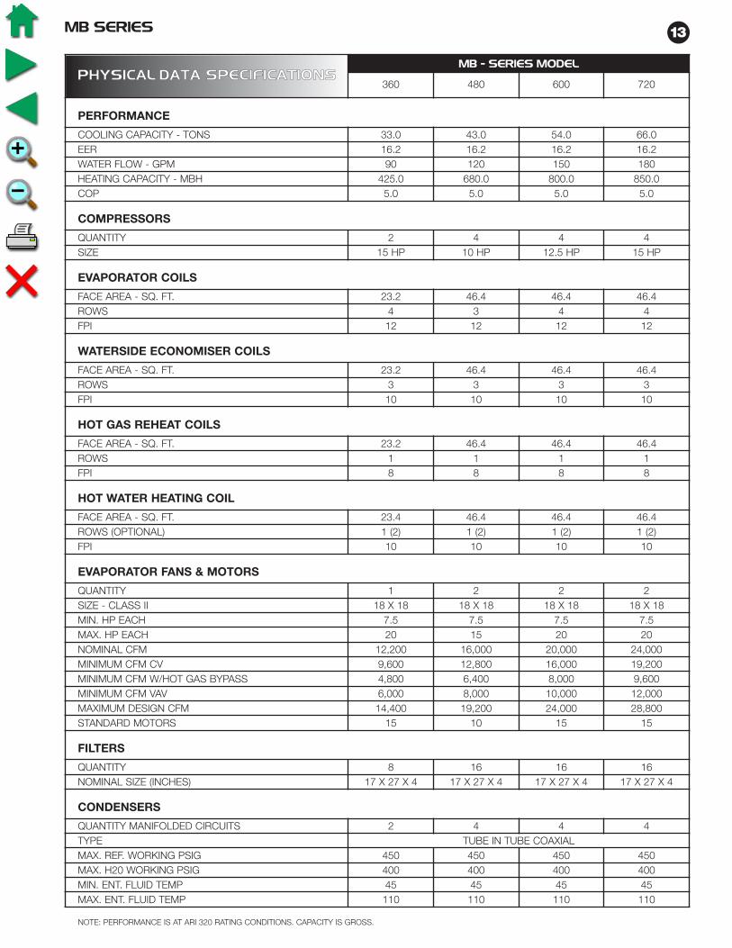
13MB SERIES
NOTE: PERFORMANCE IS AT ARI 320 RATING CONDITIONS. CAPACITY IS GROSS.
PPHHYYSSIICCAALL DDAATTAA SSPPEECCIIFFIICCAATTIIOONNSSMB - SERIES MODEL
360 480 600 720
PERFORMANCE
COOLING CAPACITY - TONS 33.0 43.0 54.0 66.0EER 16.2 16.2 16.2 16.2WATER FLOW - GPM 90 120 150 180HEATING CAPACITY - MBH 425.0 680.0 800.0 850.0COP 5.0 5.0 5.0 5.0
COMPRESSORS
QUANTITY 2 4 4 4SIZE 15 HP 10 HP 12.5 HP 15 HP
EVAPORATOR COILS
FACE AREA - SQ. FT. 23.2 46.4 46.4 46.4ROWS 4 3 4 4FPI 12 12 12 12
WATERSIDE ECONOMISER COILS
FACE AREA - SQ. FT. 23.2 46.4 46.4 46.4ROWS 3 3 3 3FPI 10 10 10 10
HOT GAS REHEAT COILS
FACE AREA - SQ. FT. 23.2 46.4 46.4 46.4ROWS 1 1 1 1FPI 8 8 8 8
HOT WATER HEATING COIL
FACE AREA - SQ. FT. 23.4 46.4 46.4 46.4ROWS (OPTIONAL) 1 (2) 1 (2) 1 (2) 1 (2)FPI 10 10 10 10
EVAPORATOR FANS & MOTORS
QUANTITY 1 2 2 2SIZE - CLASS II 18 X 18 18 X 18 18 X 18 18 X 18MIN. HP EACH 7.5 7.5 7.5 7.5MAX. HP EACH 20 15 20 20NOMINAL CFM 12,200 16,000 20,000 24,000MINIMUM CFM CV 9,600 12,800 16,000 19,200MINIMUM CFM W/HOT GAS BYPASS 4,800 6,400 8,000 9,600MINIMUM CFM VAV 6,000 8,000 10,000 12,000MAXIMUM DESIGN CFM 14,400 19,200 24,000 28,800STANDARD MOTORS 15 10 15 15
FILTERS
QUANTITY 8 16 16 16NOMINAL SIZE (INCHES) 17 X 27 X 4 17 X 27 X 4 17 X 27 X 4 17 X 27 X 4
CONDENSERS
QUANTITY MANIFOLDED CIRCUITS 2 4 4 4TYPE TUBE IN TUBE COAXIALMAX. REF. WORKING PSIG 450 450 450 450MAX. H20 WORKING PSIG 400 400 400 400MIN. ENT. FLUID TEMP 45 45 45 45MAX. ENT. FLUID TEMP 110 110 110 110

MB SERIES14
CFM GPM
MB360 12,000
MB480 16,000
MB600 20,000
MB720 24,000
609090120120150150180
336.0378.0504.0552.0620.0660.0716.0756.0
258.0276.0364.0384.0452.0472.0536.0552.0
• Capacities at 80˚F DB, 67˚F WB entering air and 45.0˚F entering water.
AIRFLOW
To obtain economizer performance multiply the base performance by the CFM correctionfactor, entering air correction factor and entering fluid temperature factor as applicable
WWAATTEERR--SSIIDDEE EECCOONNOOMMIIZZEERR PPEERRFFOORRMMAANNCCEE
COOLING CAPACITY
TOTAL MBH SENSIBLE MBH
PERCENTAGE CFM
-20%
-10%
STANDARD
+10%
+20%
TOTAL COOLING CAPACITY
0.920
0.960
1.000
1.040
1.080
SENSIBLE COOLING CAPACITY
0.870
0.930
1.000
1.060
1.120
CCOORRRREECCTTIIOONN FFAACCTTOORRSS
ENTERING AIR TEMPERATURE
ENTERING WB TOTAL CAPACITY˚F CORRECTION
57 0.851
61 0.910
64 0.955
67 1.000
73 1.090
78 1.164
SENSIBLE CAPACITY CORRECTION
ENTERING DB °F
ENTERING FLUID TEMPERATURE
ENTERING FLUIDTEMPERATURE ˚F
45
50
55
60
65
70
TOTAL COOLING CAPACITY
1.000
0.790
0.610
0.470
0.350
0.240
SENSIBLE COOLING CAPACITY
1.000
0.890
0.780
0.470
0.350
0.240
70
0.961
0.763
0.615
75
1.030
0.881
0.733
80
1.148
1.000
.703
85
1.267
.970
.723
95
1.257

15MB SERIES
MB360
MB480
MB600
MB720
60
120
120
120
6,000
12,000
14,000
8,000
16,000
18,000
16,000
20,000
24,000
20,000
24,000
28,000
349
488
523
558
808
856
808
898
976
898
976
1046
113.4
97.3
94.3
124.0
106.3
103.6
106.3
101.2
97.3
101.2
97.3
94.3
168.4
163.7
162.6
170.7
166.5
165.7
166.5
165.0
163.7
165.0
163.7
162.6
MODEL WATERGPM
AIRFLOW CFM
CAPACITYMBH
LEAVING AIR˚F
LEAVING WATER˚F
Coil performance is based on entering air temperature of 60˚F and 180˚F entering water.Please contact your FHP representative for performance at other conditions and two row coil performance data.
OONNEE RROOWW HHOOTT WWAATTEERR CCOOIILL CCAAPPAACCIITTYY

MB SERIES16
WWAATTEERR--SSIIDDEE CCOOMMPPOONNEENNTT PPRREESSSSUURREE DDRROOPPSS -- ((FFtt.. ooff HH2200))
NOTE: ECONOMISER PRESSURE DROP INCLUDES MOTORIZED BALL VALVE AND ALL ASSOCIATED PIPING.HOT WATER COIL IS 1 ROW
NOTE: 1) Cooling coil and economiser coil shown with wet surface.2) Reheat coil and hot water coil shown dry.3) Filters shown clean.4) Two-row hot water coil shown.
GPM
60
70
80
90
90
100
110
120
120
130
140
150
150
160
170
180
CONDENSERS
8.7
11.8
15.4
19.5
8.4
10.3
12.6
15.0
8.7
10.1
11.7
13.5
13.5
15.4
17.4
19.5
ECONOMISER
13.1
17.9
23.5
29.8
7.3
9.1
11.0
13.1
13.1
15.4
17.9
20.6
20.6
23.5
26.5
29.8
HOT WATER COIL
4.2
5.7
7.5
9.5
2.6
2.9
3.5
4.2
4.2
4.9
5.7
6.6
6.6
7.5
8.5
9.5
MODEL
MB360
MB480
MB600
MB720
AAIIRR--SSIIDDEE PPRREESSSSUURREE DDRROOPPSS -- ((IINNCCHHEESS OOFF HH22OO))
MODEL CFMCOILS FILTERS
FACEVELOCITYCOOLING ECONOMISER REHEAT
HOTWATER
4" - 30% 4" - 65%
MB360
8,000 0.35 0.25 0.06 0.12 0.07 0.24 345
10,000 0.53 0.32 0.07 0.17 0.12 0.30 431
12,000 0.77 0.47 0.12 0.25 0.19 0.43 517
13,000 0.90 0.56 0.15 0.29 0.22 0.51 560
MB480
12,000 0.26 0.15 0.02 0.06 0.05 0.10 259
14,000 0.36 0.20 0.04 0.09 0.06 0.14 302
16,000 0.47 0.26 0.05 0.11 0.09 0.19 345
18,000 0.59 0.33 0.06 0.15 0.11 0.24 388
MB600
16,000 0.35 0.25 0.06 0.12 0.07 0.24 345
18,000 0.43 0.28 0.07 0.16 0.10 0.26 388
20,000 0.53 0.32 0.07 0.17 0.12 0.30 431
22,000 0.64 0.40 0.12 0.24 0.15 0.40 474
MB720
20,000 0.53 0.32 0.07 0.17 0.12 0.30 431
22,000 0.64 0.40 0.12 0.24 0.15 0.40 474
24,000 0.77 0.47 0.12 0.25 0.19 0.43 517
25,000 0.84 0.52 0.14 0.26 0.20 0.47 539

17MB SERIES
BBLLOOWWEERR PPEERRFFOORRMMAANNCCEE
MB360
MB480 - 720
1000 CFM

MB SERIES18
Note: 1) For the specific application CFM and TSP select the part number and motor HP.2) MB480, 600 and 720 require a quantity of 2 drive packages.
DDRRIIVVEE SSEELLEECCTTIIOONN TTAABBLLEE
CFM
TOTAL STATIC PRESSURE - INS WATER
2.0 2.5 3.0 3.5 4.0 4.5
DrivePart #
HP DrivePart #
HP DrivePart #
HP DrivePart #
HP DrivePart #
HP DrivePart #
HP
041 041 041 041 041 041
MB360
9,500 -002 7.5 -006 15 -011 10 -018 15 -024 15 -030 15
10,000 -002 7.5 -008 10 -011 10 -017 15 -024 15 -030 15
10,500 -040 10 -008 10 -014 15 -018 15 -024 15 -030 15
11,000 -040 10 -008 10 -014 15 -017 15 -024 15 -030 15
11,500 -006 15 -009 15 -014 15 -018 15 -024 15 -031 20
12,000 -006 15 -012 15 -014 15 -021 15 -025 20 -030 20
12,500 -006 15 -012 15 -018 15 -022 20 -025 20 -031 20
13,500 -009 15 -015 20 -019 20 -022 20 -027 20 - -
MB480 - REQUIRES TWO MOTORS
13,000 000 7.5 -007 7.5 -013 7.5 -023 7.5 -041 10 -036 10
14,000 000 7.5 -005 7.5 -013 7.5 -020 10 -029 10 -036 10
15,000 000 7.5 -005 7.5 -013 7.5 -020 10 -029 10 -037 15
16,000 000 7.5 -005 7.5 -013 7.5 -017 10 -026 10 -037 15
17,000 000 7.5 -005 7.5 -013 7.5 -017 10 -024 15 -042 15
18,000 -002 7.5 -005 7.5 -011 10 -017 10 -024 15 -030 15
19,000 -002 7.5 -006 15 -011 10 -018 15 -024 15 -030 15
MB600 - REQUIRES TWO MOTORS
16,000 000 7.5 -005 7.5 -013 7.5 -017 10 -026 10 -037 15
17,000 000 7.5 -005 7.5 -013 7.5 -017 10 -024 15 -042 15
18,000 -002 7.5 -005 7.5 -011 10 -017 10 -024 15 -030 15
19,000 -002 7.5 -006 15 -011 10 -018 15 -024 15 -030 15
20,000 -002 7.5 -008 10 -011 10 -017 15 -024 15 -030 15
21,000 -040 10 -008 10 -014 15 -018 15 -024 15 -030 15
22,000 -040 10 -008 10 -014 15 -017 15 -024 15 -030 15
23,000 -006 15 -009 15 -014 15 -018 15 -024 15 -031 20
24,000 -006 15 -012 15 -014 15 -021 15 -025 20 -030 20
MB720 - REQUIRES TWO MOTORS
19,000 -002 7.5 -006 15 -011 10 -018 15 -024 15 -030 15
20,000 -002 7.5 -008 10 -011 10 -017 15 -024 15 -030 15
21,000 -040 10 -008 10 -014 15 -018 15 -024 15 -030 15
22,000 -040 10 -008 10 -014 15 -017 15 -024 15 -030 15
23,000 -006 15 -009 15 -014 15 -018 15 -024 15 -031 20
24,000 -006 15 -012 15 -014 15 -021 15 -025 20 -030 20
25,000 -006 15 -012 15 -018 15 -022 20 -025 20 -031 20

19MB SERIES
NET WEIGHT IN LBS.
MMBB SSEERRIIEESS SSHHIIPPPPIINNGG WWEEIIGGHHTTSS ((LLBBSS))
MODEL MB360 MB480 MB600 MB720 MB360 MB480 MB600 MB720
VH CONFIGURATION VL CONFIGURATION
MAIN AIR CONDITIONING SECTION (EACH)
NUMBER OF SECTIONS 1 2 2 2 1 2 2 2
MAIN SECTION EACH 1,450 1,175 1,550 1,575 2,100 1,825 2,200 2,225
REHEAT COIL OPTION EACH 40 40 40 40 40 40 40 40
FILTER/ECONOMISER SECTIONS (EACH)
NUMBER OF SECTIONS 1 2 2 2 1 2 2 2
FILTER SECTION 310 310 310 310 310 310 310 310
ECONOMISER OPTION 200 200 200 200 200 200 200 200
BLOWER SECTION (EACH)
NUMBER OF SECTIONS 1 2 2 2
INCLUDED IN MAIN AC SECTION
FAN SECTION (MAX MOTOR SIZE) 650 650 650 650
TOTAL UNIT
NUMBER OF SECTIONS 3 6 6 6 2 4 4 4
TOTAL UNIT WITH OPTIONS 2,650 4,750 5,500 5,550 2,650 4750 5500 5550

MB SERIES20
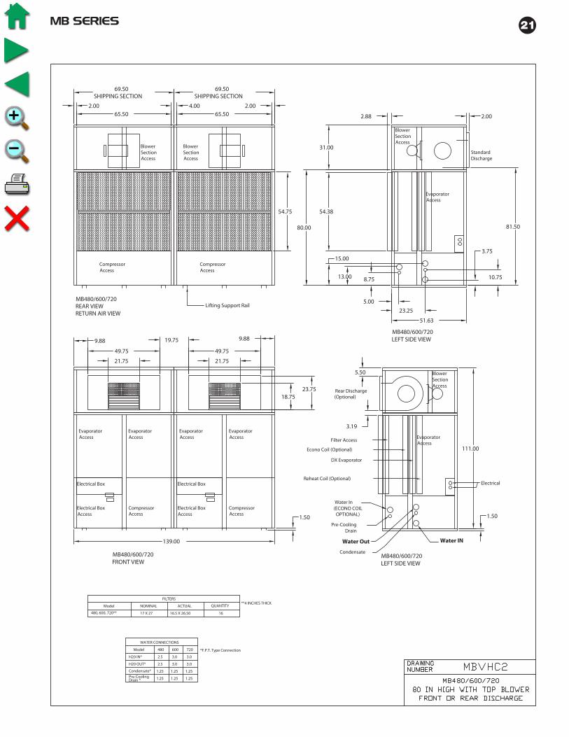
21MB SERIES

MB SERIES22

23MB SERIES

MB SERIES24
UNIT ELECTRICAL SPECIFICATIONS
General
Wiring must comply with applicable codes.A single power block is provided for power cables to the unit.Each individual module has it’s own terminal block and wiring between sections follows the concept of single pointpower supply.
Unit Disconnect
Unit disconnects are required under Article 440 of the National Electric Code. The disconnect switch should be locatedin accordance with NEC guidelines. Unit disconnects are not factory installed.
Notes:1. Model MB 360 uses one motor/blower assembly2. Models MB480,600 and 720 use 2 motor/blower assemblies3. All motors are high efficiency open drip proof and meet all EPACT efficiency requirements.4. Service factor is 1.15 on all motors.
Note: All units are three phase power supply. Check compressor and blower rotations at start-up. See unit nameplatefor allowable voltage tolerances.
Power lead wire sizing.
Minimum circuit ampacity: (largest load x 1.25) + all other loadsMax fuse size: (largest load x 2.25) + all other loads - use next smaller fuse size.All wiring to be in accordance with N.E.C. table 310-16 or 310-19
MMOOTTOORR NNAAMMEEPPLLAATTEE DDAATTAA
HORSEPOWER230-3-60 460-3-60 575-3-60
FLA FLA FLA
5.0 12.8 6.4 5.4
7.5 19.4 9.7 7.8
10.0 25.8 12.9 10.3
15.0 38.6 19.3 15.4
20.0 49.6 24.8 19.8
CCOOMMPPRREESSSSOORR NNAAMMEEPPLLAATTEE DDAATTAA
MODEL QTY.230-3-60 460-3-60 575-3-60
RLA (EA.) LRA (EA.) RLA (EA.) LRA (EA.) RLA (EA.) LRA (EA.)
MB360 2 62.2 376 27.6 178 20.5 148
MB480 4 42.0 239 19.2 125 12.4 80
MB600 4 47.1 318 22.6 158 17.3 125
MB720 4 62.2 376 27.6 178 20.5 148

25MB SERIES
MC
S C
ON
TR
OLLE
R
TYP
ICA
L WIR
ING
DIA
GR
AM

MB SERIES26

27MB SERIES

MB SERIES28
GENERAL
Furnish and install where shown on plans, FHPManufacturing MB Series self-contained packaged airconditioning unit. Capacities, models and unitarrangement shall be as shown on the unit scheduleand the contract drawings. Units shall be listed for ULand CUL. Units shall conform to ANSI/UL standard1995. Unit shall be accepted for use in the City of NewYork by the Department of Buildings (MEA). Each unitshall be completely factory assembled, piped, wiredand tested. Units shall be leak tested and charged witha full operating charge of Refrigerant 22. Units shallthen be disassembled into their individual modules forshipping and assembly on site. Unit ratings will be inaccordance with latest ARI Standard 320. Installationand maintenance manuals and wiring diagrams shall besupplied with each unit. Factory test shall include, butnot be limited to: complete run check of all electricalcomponents and safeties, including proper controlsequencing; pressure test of refrigerant coils andcondensers; leak check of completed refrigerantcircuits; leak check of completed water circuit;compressor run check.
CABINET
VH CONFIGURATION:The unit shall be comprised of three distinct modules:1) Main cooling/heating, 2) Filter/watersideeconomizer, and 3) Fan section. The unit shall bedesigned for easy assembly. The refrigeration circuitshall remain intact during disassembly/assembly. Allmodules shall be able to pass through a 36" steelframed door. The frame shall be fabricated of an angleiron framework. Unit exterior panels shall be 18 gaugeG90 galvanized steel for corrosion protection. Eachsection shall incorporate removable access panels.The complete cabinet frame and access panels shallbe insulated with 1/2 inch, dual density Neoprenebacked fiberglass fiber insulation. The maincooling/heating section and the filter/watersideeconomizer section shall contain a galvanized steeldrain pan coated with archem type paint for corrosionresistance.
VL CONSTRUCTION:The unit shall be comprised of two distinct modules:1) Main cooling/heating section with blower(s) andmotor(s) 2) Filter/waterside economizer section. The
unit shall be designed for easy assembly. Therefrigeration circuit shall remain intact duringdisassembly/assembly. The frame shall be fabricatedof an angle iron framework. Unit exterior panels shallbe 18 gauge G90 galvanized steel for corrosionprotection. Each section shall incorporate removableaccess panels. The complete cabinet frame andaccess panels shall be insulated with 1/2 inch, dualdensity Neoprene backed fiberglass fiber insulation.The main cooling/heating section and thefilter/waterside economizer section shall contain agalvanized steel drain pan coated with archem typepaint for corrosion resistance.
EVAPORATOR
The direct expansion coil shall be a minimum of 3 rowsand fabricated from 3/8" or 1/2" O.D. seamless coppertubing mechanically bonded to rippled and corrugatedaluminum fins. Each individual evaporator coil shall beremovable for replacement without disturbing theremaining refrigerant circuits. Each evaporator coilcircuit shall be fed by an adjustable thermostaticexpansion valve, with external equalizer, sized toprovide efficient operation at full and at part loadoperating points in the cooling and heating modes.
SUPPLY FAN
Supply fans shall be double width, double inlet forwardcurved type of Class II construction. All fans shall bestatically and dynamically balanced. Fan shafts shall bemounted in heavy duty 150,000 hour greaseable pillowblock bearings. The fan motor shall be open drip proofthree phase, NEMA T frame E high efficiency EPACTrated, 1800 rpm, with grease lubricated ball bearings.The drive shall include fixed pitch sheaves with multipleV belts sized for 115% of the fan brake horsepower.
REVERSE CYCLE OPERATION
Units shall be equipped with reversing valves to allowoperation in the reverse cycle heating mode. Electricheaters shall not be allowed as a substitute.
VARIABLE AIR VOLUME, (OPTIONAL)
Airflow modulation shall be achieved by the use of afactory controlled variable frequency drive. The unitshall be able to operate at 100% of rated airflow in theevent of a failure of the VFD. Static pressure shall becontrolled by the unit mounted MCS controller. Static
GUIDESPECIFICATIONS
MB SERIESVERTICAL PACKAGE UNITSFHP MANUFACTURING
ENERGY WISE HVAC EQUIPMENT

29MB SERIES
pressure to be sensed by field installed duct sensors.The installer to provide and install wiring from thesensor to the unit mounted controller. The staticpressure setpoint shall be keypad adjustable throughthe MCS controller.
REFRIGERATION CIRCUIT
Each unit shall contain multiple independentrefrigeration circuits. Each circuit shall include a highefficiency heavy-duty scroll compressors. Each circuitshall have high and low pressure cutouts. Each circuitshall be dehydrated and factory charged withRefrigerant 22. Suction and discharge schrader valvesshall be provided for manifold gauge connections to facilitateservicing. Optional hot gas bypass shall be provided to allowunit operation under extended operating conditions avoidingcoil freeze up.
COMPRESSORS
Each unit shall have multiple high efficiency scrollcompressors with internal or external motor protectionand a time delay to prevent short cycling andsimultaneous starting of compressors following apower failure. Each compressor shall be on anindependent refrigerant circuit. The compressors shallbe mounted on rubber isolators.
CONDENSERS
All condensers shall be coaxial tube-in-tube formaximum heat transfer efficiency and performance.Inner water tubes shall be either copper or optionalcupro-nickel with large internal diameters for reducedwaterside pressure drops. Outer tubes shall be steel,painted for corrosion protection. All condensers shallbe rated at 450 PSIG operating refrigerant pressuresand 400 PSIG waterside pressures. Units shall berated down to 45°F without the use of water regulatingvalves.
WATERSIDE ECONOMIZER, (OPTIONAL)
A complete waterside economizer package shall beprovided, including coil, control valves and factorypiping. The complete economizer package shall berated for 400 psig waterside working pressure.Economizer operation shall be controlled to maximizefree cooling operation. Economizer shall be enabled bythe optional MCS controller whenever the enteringwater temperature is less than an adjustable set point.Water flow shall pass through the economizer coil andcondenser in series while in the economizer operatingmode and shall bypass the economizer coil while notcalling for economizer operation. Mechanical coolingor heating shall be enabled during economizeroperation.
HOT WATER PREHEAT, (OPTIONAL)
Hot water coils shall be 1 or 2 rows, fabricated from1/2"O.D. seamless copper tubing mechanicallybonded to rippled and corrugated aluminum fins. Coilshall be field mounted.
HOT GAS REHEAT, (OPTIONAL)
Provide a one row hot gas reheat coil to allow the unitto operate in the dehumidification mode. Control of thehot gas reheat shall be provided by the unit controller.
FILTER SECTION
The unit shall be supplied with 4" deep pleated, 30%high efficiency filters. The filters shall have side accesscapability through an access panel.
ELECTRICAL
Each unit shall be wired and tested at the factory priorto shipment. Wiring shall comply with NECrequirements and shall conform with all applicable ULstandards. The units shall have a single point powerconnection. The control power shall be suppliedthrough a factory installed, low voltage control circuittransformer with an integral resettable circuit breaker.The fan motor starter shall have a magnetic three line,ambient compensated overload protector with amanual reset. A terminal block shall be provided for themain power connection.
Each unit shall be provided with a Unit ProtectionModule (UPM) that controls compressor operation andmonitors the safety controls that protect the unit.
Safety controls include the following:
• High pressure switches located in the refrigerantdischarge lines. One per refrigeration unit.
• Low pressure switches for loss of chargeprotection located in the unit refrigerant suctionlines. One per refrigeration unit.
• Optional freeze protection sensor located on theleaving side of the water coil prevents unitoperation below 35ºF. Freeze terminals must bejumped together if the freeze sensor is notinstalled.
• Condensate overflow protection sensor located inthe drain pan(s) of the unit and wired to the UPMboard.
The UPM includes the following features:
• ANTI-SHORT CYCLE TIMER – 5 minute delay onbreak timer to prevent compressor short cycling.
• RANDOM START – Each controller has a uniquerandom start delay ranging from 30 to 60 seconds.
• LOW PRESSURE BYPASS TIMER – The lowpressure switch will be bypassed for 90 secondsafter compressor start-up to prevent nuisance lowpressure lockouts during cold start-up in theheating mode.
• BROWNOUT/SURGE/POWER INTERRUPTIONPROTECTION – a 20 millisecond window is to bemonitored for the above condition. Should any ofthese conditions be detected, the 5-minute delayon break timer and the random start timer delayare initiated.
MB SERIES30
• MALFUNCTION OUTPUT – The controller shallhave a set of wet contacts for remote faultindication.
• TEST SERVICE PIN – A jumper pin is to beprovided to reduce all time delay settings to 5seconds during troubleshooting or verification ofunit operation.
• L.E.D. FAULT INDICATION – Two L.E.D.indicators are provided as follows:
• GREEN: Power L.E.D. indicates 18 – 30 VACpresent at the board.
• RED: Fault indicator with blink codes as follows:
•• ONE BLINK 1st Stage high pressure lockout
•• TWO BLINKS 1st Stage low pressure lockout
•• THREE BLINKS 2nd Stage high pressure lockout
•• FOUR BLINKS 2nd Stage low pressure lockout
•• FIVE BLINKS Freeze protection lockout
•• SIX BLINKS Condensate overflow lockout
• INTELLIGENT RESET - If a fault condition is initiatedthe 5 minute delay on break time period and therandom start timer are initiated and the unit will restartafter these delays expire. During this period the faultLED will indicate the cause of the fault. If the faultcondition still exists or reoccurs before the thermostatis satisfied, the unit will go into a hard lockout andrequires a manual lockout reset.
• LOCKOUT RESET - A hard lockout can be reset byturning the unit thermostat off and then back on or byshutting off unit power at the circuit breaker.
NOTE: The blower motor will remain active duringa lockout condition.
AUXILIARY CONTROL OPTIONS
A pressure differential type water flow switch shall beprovided, factory installed, to verify water flow status atthe unit. Compressor operation shall be disabled andan alarm signal provided if condenser water flow islost. Unit operation will be restored when water flowhas been reestablished. Water flow status shall bedisplayed at the unit's English language display.
MCS CONTROLLER (OPTIONAL)
Please refer to MCS unit controller manual.

31MB SERIES
NOTES

HVA
C EQ
UIP
MEN
TH
VA
C EQ
UIP
MEN
T
CommercialWater Source andGeothermal Products
EN
ER
GY
WIS
E
CO
MM
ER
CIA
L P
RO
DU
CT
S
FHP MANUFACTURING601 N.W. 65th CourtFort Lauderdale, FL 33309(954) 776-5471(800) 776-5529 Faxwww.fhp-mfg.com
SMALL VERTICALMODELS
1/2 - 5 TONS
ROOFTOPMODELS
4 - 35 TONS
LARGE HORIZONTALMODELS
6 - 12 TONS
SMALL HORIZONTALMODELS
1/2 - 5 TONS
CONSOLEMODELS
3/4 - 11/2 TONS
PRODUCT OFFERING• Vertical Units ..................................................................................................................................1/2 - 60 Tons• Horizontal Units ..............................................................................................................................1/2 - 12 Tons• Console Units ...............................................................................................................................3/4 - 11/2 Tons• Rooftop Units ..................................................................................................................................4 - 35 Tons• Water to Water Chillers / Boilers ......................................................................................................3 - 40 Tons• Split Systems .................................................................................................................................1/2 - 25 Tons• Variable Air Volume .........................................................................................................................6 - 60 Tons
FACTORY INSTALLED OPTIONS• Hot Gas Reheat ( Dehumidification ) • 100% Outside / Make up Air Units• Water-side Economizer • Cupronickel Water Coil• Heat Recovery ( Desuperheater ) • Custom Options Available Upon Request
SOFTWAREOur Engineering Application Data Software ( EAD ) is customized for the professional HVAC designer. ProfessionalHVAC designers will find this software to be an instrumental tool for equipment selection. Our EAD Software isavailable for HVAC designers via our web site at www.fhp-mfg.com free of charge.
LARGE VERTICALMODELS
6-60 TONS
REV. 12/03