mcc - columbus-klima.hu
TRANSCRIPT

������������� ������������� �����������������

2RG66002701 - Rev 00
MCC
The technical and dimensional data reported in this manual may be modified
INDEX
1 The range ................................................................................ 22 Constructive features .............................................................. 33 Components lay-out ................................................................ 54 Models and configurations ...................................................... 65 Rated technical data ............................................................... 75.1 Cooling only units rated technical data ..................................... 75.2 Heat pumps units rated technical data ..................................... 76 Performances ......................................................................... 86.1 MCC-C cooling operation ......................................................... 86.2 MCC-H cooling operation ........................................................ 106.3 MCC-H heating operation ........................................................ 127 Operations limits ................................................................... 147.1 Cooling mode ......................................................................... 147.2 Heating mode ......................................................................... 148 Heat recovery options ............................................................ 149 Calculation factors ................................................................. 149.1 Water temperature drop/rise different yhan 5°C ....................... 149.2 Glycol and water solution ....................................................... 1410 Pressure drop on water side .................................................. 1511 Unit available pressure head ................................................. 1612 Water circuit .......................................................................... 1713 Electrical data ........................................................................ 1814 Overall dimensions ................................................................ 1915 Installation clearance requirements ...................................... 2316 Siting ..................................................................................... 24
1 THE RANGE
The series MCC of the air cooled water chillers and heating pumps hasbeen designed for indoor installation, for residential and commercialapplications, when duct connection is required.
The series MCC has been designed and developed with the 410 A refrigerant,in fact the unit reaches excellent level of energetic efficiency thanks to theoptimization of the heat exchangers in the type of plates and the distributionof the refrigerant.
The logic of the Plug&Play on the hydraulic side- already present (DNA) in allour water chillers models - here is going alongside with the Plug&Play on thefans group : Auto - adaptive control of the air flow and the constant fan speedmodulations (condensation control on pressure basis) reduces the installationcosts and timing.
> PLUG&PLAY ON AIR SIDE:Autoadatptive air flow depending on:- pressure drop on air side- inlet air temperatureAll units comes with modulating continuous fan speed control that adjustthe rpm of the motor depending on the air temperature and air pressure drop,using a cutting-phase device.Air outlet can be vertical or horizzontal (optional).
> HYDRAULIC PLUG&PLAY3 different hydraulic kits are available to enable an easy installation of MCCunits in the cooling and heating system:- B version: standard unit with evaporator- P version: unit with evaporator, pump and expansion vessel- S version: unit with evaporator, pump, expansion vessel and water tank
> SIMPLIFIED MAINTENANCECentrifugal fans are directly coupled to the eletric motor without using pulleyand belt system.The compressor and technical compartment is completly separated fromthe fan compartment in order to perform check operation while the unit isoperating .Easily accessible electronic microprocessor control.
> ELECTRONIC MICROPROCESSOR CONTRO PANEL
Brand new technology, it allows the connection with ERGO
Adjustable set-point thanks to an outdoor temperature probe (optional).
DECLARATION OF CONFORMITY Galletti S.p.A. hereby declares, under its sole responsibility, that thewater chillers and heat pumps belonging to the MCC series have beendesigned, built and tested in conformity with the specifications ofEuropean Directives:· 98/37/CE (Machinery Directive)· 73/23/CEE (Low Voltage Directive)· 89/336/CEE (Directive on Electromagnetic Compatibility)· 97/23 CE (PED)Bentivoglio, 04/07/2006Galletti S.p.A.Luigi Galletti
The technical and dimensional data reported in this manual may be modifiedin view of any product improvement.

3 RG66002701 - Rev 00
The technical and dimensional data reported in this manual may be modified
MCC
2 CONSTRUCTIVE FEATURES
REFRIGERANT GAS: R410A
STRUCTUREGalvanised sheet steel supporting base and enclosing panels made ofPeraluman to ensure effective protection against corrosive agents.All bolts and screws and fastening devices are made of non-oxidisablematerials, or carbon steel that has undergone surface-passivating treatments.The compressor compartment is completely sealed, acoustically isolatedand may be accessed on 2 sides (electric board side and plumbingconnection side) thanks to easy-to-remove panels that greatly simplifymaintenance and inspection.The ventilation compartment is separated from the compressor compartmentof the unit, for inspection purposes when the unit is working.For lifting the unit, ø 40-mm holes are provided in the base, through whichlifting pipes can be inserted and the vibration-damping feet can be accessedfor fastening.
MICROPROCESSOR CONTROLThe control panel enables the complete control of the MCC unit. It can beeasily accessed through a polycarbonate flap with IP65 protection rating.Main functions- Control over the temperature of water entering the evaporator- Defrosting management (heat pumps) via pressure control- Control of fan speed via pressure probe- Complete alarm management- Can be connected to an RS485 serial line (optional) for supervisory /
teleassistance operation- Integrated MODBUS protocol- Can be connected to ERGO networks (via RS485 optional)- A remote terminal that reproduces the control functions is available as
optional (not compatible with ERGO)- A configuration with external air probe that assures dynamic variation of
unit set point is available (optional).Controlled devices:- compressors- fans- cycle reversing valve (only for heating pump MCA-H)- circulating pump- antifreeze resistence (optional)- alarm relayThe end user can change the parameter settings shown in the table within thelimits indicated.Parameter min standard maxCooling setpoint (°C) 8 11,5 20
Heating setpoint (°C) 15 40 45
Cooling hysterisis (°C) 0,3 2 5
Heating hysterisis (°C) 0,3 3 5
Antifreeze set point (°C) -40 3 5
All other parameters may be adjusted by an AUTHORISED SERVICE CENTREby means of a programming access key, except for the machine configuration,which may be modified exclusively by GALLETTI S.p.A.
REFRIGERANT CIRCUIT- scroll compressor fitted in a sound proofed compartment- heat exchanger with stainless steel braze-welded plates optimised for
type of plate and distribution for R410A.- finned block condenser coil with copper pipping and aluminium fins.- dehydration filter.- refrigerant sight glass with humidity indicator.- thermostatic valve with external equalization and integrated MOP function.- cycle - reversing valve (heat pump models only).- check valves (heat pump only).- liquid receiver (heat pump only).- high and low pressure switches.- safety valve.- Schrader valves for checks and/or maintenance.- refrigerant manometers (options).
TAYLORED HYDRONIC KITTo simplify the connection of the MCC unit to user plant , 3 different hydraulic
kit are available.:- base unit (MCC..B)- kit including water pump and expansion vessel (MCC..P)- kit including water pump and expansion vessel and buffer tank (MCC..S)The main features are:- High performance pump with extended working range: suitable to operate
with glycol mix up to 30%.The pump is fitted in the compressors vane,acoustically insulated and of easy access thanks to the openablepanels.The pump is provided with internal thermal protection.The water pump is cooled by the external air through a suitable grille.
- expansion vessel- water safety valve- automatic filling system- automatic vent valve- differential pressure switch and antifreeze thermostat with probe on leaving
water side.- buffer tank dowstream to the evaporator, best solution to reduce the
chilled water variation due to the compressor ON/OFF operation.

4RG66002701 - Rev 00
MCC
The technical and dimensional data reported in this manual may be modified
MCC 06 - 07
3 COMPONENTS LAY-OUT
2 CONSTRUCTIVE FEATURES
VENTILATION SECTIONStatically and dynamically balanced centrifugal fans with forward-curvingblades, directly mounted on the electric motor. All electric fans are mountedon an appropriate structure with interposed vibration dampers to reduce thepropagation of vibrations.All units are equipped with phase-cut speed regulator controlled by the pressureprobe.The ventilation compartment is completely insulated with anti-condensationmaterial and separated from the compressor/electrical system compartmentfor inspection purposes when the unit is working (without interfering with thefinned block exchanger).The absence of belt drive and the frontally removable fan considerably reducemaintenance work.
FINNED BLOCK HEAT EXCHANGERBuilt with 3/8" copper piping and aluminium fins.The special engineering of the heat exchangers allows defrost cycles to becarried out at maximum speed in the models with heat pump operation, whichbrings clear benefits in terms of the integrated efficiency of the whole cycle.The condenser coil can be fitted with a metal filter that is easily removed fromthe machine side panels in case of ducted air intake.With heat pumps, an aluminium condensate drip pan is mounted that can beducted. To prevent ice from forming, a heating cable is installed in the heatexchanger base.
ELECTRIC PANELThe electric panel is built and wired according to the CEE 73/23 directive, tothe 89/336 directive for the electromagnetic compatibility and related standards.Built with steel panels sheet, completely closed and protected by the enclosingpanels of the unit.It is composed by:- compressors conctactors- pump relay- pump, fans, trasformer and main control box protection fuses- 230V/24V tranformer- terminal box
AVAILABLE OPTIONS- refrigerant gauges- antifreeze kit- electronic expansion valve- partial heat recovery system 20%(cooling only model)- special treatment on coils (copper/copper, cataphoresys,Blygold)- remote control board (PCD)- simplified remote board (PDCS)- antivibration mounting.- protecting grid for condensing coils.- air delivery connectors
Description1 R410A-air heat-exchangers
2 R410A-water heat-exchanger
3 Fan
4 Water differential pressure switch
5 Air purge valve
6 Expansion vessel
7 Water tank
8 R410A safety valve
9 4-way valve (MCC H)
10 Thermostatic valve
11 Automatic filling device
12 Water safety valve
13 Liquid receiver
14 Pump
15 Compressor
16 Refrigerant filter
17 Low pressure switch and charge port
18 High pressure switch and charge port
19 Port on refrigerant circuit (high)

5 RG66002701 - Rev 00
The technical and dimensional data reported in this manual may be modified
MCC
3 COMPONENTS LAY-OUT
MCC 09 - 15
MCC 25- 37
� �
MCC 18 - 22
Description1 R410A-air heat-exchangers
2 R410A-water heat-exchanger
3 Fan
4 Water differential pressure switch
5 Air purge valve
6 Expansion vessel
7 Water tank
8 R410A safety valve
9 4-way valve (MCC H)
10 Thermostatic valve
11 Automatic filling device
12 Water safety valve
13 Liquid receiver
14 Pump
15 Compressor
16 Refrigerant filter
17 Low pressure switch and charge port
18 High pressure switch and charge port
19 Port on refrigerant circuit (high)

6RG66002701 - Rev 00
MCC
The technical and dimensional data reported in this manual may be modified
4 MODELS AND CONFIGURATIONS
The range is madde of 10 models cooling only, cwith cooling capacities from 6 to 37 kW and 10 models heat pump operation with heating capacity from 6to 41 kW.To simplify the way of making the order, Galletti offers 3 different solutions of hydraulic kit built in the unit, for only cooling only and heating pumps units.
WATER CHILLERMCC..CB basic unit (only evaporator)MCC..CP unit with pump and expansion vesselMCC..CS unit with buffer tank ,pump and expansion vessel
HEAT PUMPMCC..HB basic unit (only evaporator)MCC..HP unit with pump and expansion vesselMCC..HS unit with buffer tank ,pump and expansion vessel
The choice of some options can prevent the choice of some options or oblige the selection of other fields. To contact the Galletti for verification
M C C 0 1 2 C 0 A A A 1 S 0 C S 0 M 0 0 0 0 0
0 1 2CCH
002M
A0A
101
S0S
00D
CC
S0EPS
00SM
M0M
002
00RCB
00RFMetallic filter
Not present Protection grille
Copper / copper heat exchanger Cataphoresis
BlygoldCoil special execution
Not present RS 485 x ERGO (modbus built in)
Special heat exchanger featuresStandard
Refrigerant circuit optionsNot present
GaugesRemote control
Remote control boardNot present
SimplifiedWith microprocessor *
Not present Present, standard unit
Present, unit with pump and tank Present, unit with pump, tank and vessel
Partial (desuperheater) 20%Condensing control
Modulating air flow with fan speed control Antifreeze kit
Not present PresentHeat recoverNot present
Water pumpNot present
Pump and epansion vesselWater storage tank
230V - 1 - 50 Hz Expansion valve
ThermostaticElectronic
Heat pump Power supply
400V - 3 - 50 Hz400V - 3 - 50 Hz + with thermal-magnetic
Name
Gives information on the cooling capacity of the standard modelTypology
Water chiller
00123*To be requested at the moment of the order Power factor correction capacitors + Soft starter
Compressor optionsNot present
Power factor correction capacitorsSoft starter

7 RG66002701 - Rev 00
The technical and dimensional data reported in this manual may be modified
MCC
* Weights referred to version including pump and buffer tank- Cooling capacity: outdoor air temperature 35°C, water temperature 12°C / 7°C- Heating capacity: outdoor air temperature 7°C dry bulb and 6.2°C wet bulb, water temperature 40°C/45°C- Sound power level measured according to standards ISO 3741 - ISO 3744 and EN 29614-1- Sound pressure level measured at a distance of 10 m and a height of 1.5 m above the ground in a free field (fan side).- The maximum electrical input is the mains electricity that must be available in order for the unit to work.- The maximum current absorption refers to the current that will trigger the internal safety devices of the unit. It is the maximum current allowed in the unit. This value may never be exceeded; it must
be used as a reference for determining the size of the power supply line and the related safety devices (refer to the wiring diagram supplied with the units).
5 RATED TECHNICAL DATA
5.1 COOLING ONLY UNITS RATED TECHNICAL DATA
5.2 HEAT PUMP UNITS RATED TECHNICAL DATA
MCC-C 06M 07 M 09 M 6 7 9 12 15 18 22 25 33 37 Power supply V - ph - Hz Cooling capacity kW 5,70 6,90 9,20 5,70 6,95 9,25 12,00 14,60 18,00 22,30 25,50 33,10 36,70 MCC CB Total power input kW 2,61 3,17 4,81 2,58 3,03 4,61 5,70 6,40 7,50 8,95 12,10 14,90 16,30 MCC CP CS Total power input kW 2,75 3,31 5,18 2,72 3,17 4,98 6,07 6,77 7,87 9,32 12,65 15,45 16,85 Maximum power input kW 4,20 4,80 7,50 4,20 5,10 7,80 9,40 9,90 12,10 14,00 18,40 23,40 25,30 Maximum current absorption A 17,1 19,1 33,6 7,5 9,5 17,4 19,4 20,4 23,2 25,2 28,4 34,6 38,2 Starting absorbed current A 61,6 82,6 180,2 32,6 35,6 51,2 67,2 77,2 104,2 114,2 134,6 162,6 199,6 n° of scroll compressors / circuits 1/1 1/1 1/1 1/1 1/1 1/1 1/1 1/1 1/1 1/1 1/1 1/1 1/1 Refrigerant charge kg 2,80 2,90 3,70 2,80 2,90 3,70 3,80 4,80 5,90 7,50 9,70 10,00 11,30 Low/high pressure switch bar 2 / 42 2 / 42 2 / 42 2 / 42 2 / 42 2 / 42 2 / 42 2 / 42 2 / 42 2 / 42 2 / 42 2 / 42 2 / 42 n° of axial fan 1 1 1 1 1 1 1 1 1 1 2 2 2 Air flow m3/h 2500 2500 5500 2500 2500 5500 5500 5500 6500 6500 11000 13000 13000 ASEP 91 85 140 91 85 135 130 120 120 110 125 95 90 Water flow l/s 0,273 0,329 0,439 0,272 0,331 0,442 0,573 0,698 0,860 1,065 1,218 1,582 1,753 Water side pressure drop " 4,1 4,4 36,0 4,1 4,5 36,4 38,8 56,4 38,3 45,4 47,8 40,9 38,4 Available pressure head kPa 57,0 55,1 155,1 57,1 55,0 154,6 147,7 125,2 136,0 117,5 123,1 122,7 121,0 Diameter of hydrualic connections kPa 1 1 1 1/4 1 1 1 1/4 1 1/4 1 1/4 1 1/4 1 1/4 1 1/4 1 1/4 1 1/4 Water content escluding optionals dm3 2,50 2,80 3,30 2,50 2,80 3,30 3,50 4,10 4,40 5,00 6,10 7,30 7,80 Expansion tank dm3 1 1 5 1 1 5 5 5 5 5 8 8 8 Buffer tank dm3 20 20 36 20 20 36 36 36 96 96 155 155 155 Height mm 1000 1000 1160 1000 1000 1160 1160 1160 1210 1210 1400 1400 1400 Length mm 1050 1050 1250 1050 1050 1250 1250 1250 1650 1650 2250 2250 2250 Depth mm 600 600 730 600 600 730 730 730 800 800 800 800 800 Sound power level dB(A) 70 70 78 70 70 78 78 78 79 79 80 82 82 Sound pressure level dB(A) 42 42 50 42 42 50 50 50 51 51 52 54 54 Transport weight * kg 160 165 220 160 165 220 228 240 295 301 405 430 440 Operating weight * kg 168 178 239 168 178 239 248 260 375 381 546 572 583
230-1-50 400-3-50
MCC-H 06M 07 M 09 M 6 7 9 12 15 18 22 25 33 37 Power supply V - ph - Hz Cooling capacity kW 5,60 6,75 9,00 5,60 6,80 9,10 11,70 14,30 17,60 21,80 25,00 32,40 35,90 MCC HB Cooling power input kW 2,47 3,04 3,83 2,44 2,90 3,64 4,73 5,43 7,14 8,63 10,33 14,34 15,74 MCC HP - HS Cooling power input kW 2,61 3,18 4,20 2,58 3,04 4,01 5,10 5,80 7,51 9,00 10,88 14,89 16,29 Heating capacity kW 6,40 7,75 10,20 6,40 7,65 9,95 13,10 15,50 19,20 23,80 28,20 36,36 40,56 MCC HB Heating power input kW 2,86 3,38 5,20 2,94 3,23 4,90 6,10 6,72 7,75 9,20 12,30 15,20 16,70 MCC HP - HS Heating power input kW 3,00 3,52 5,57 3,08 3,37 5,27 6,47 7,09 8,12 9,57 12,85 15,75 17,25 Maximum power input kW 4,20 4,80 7,50 4,20 5,10 7,80 9,40 9,90 12,10 14,00 18,40 23,40 25,30 Maximum current absorption A 17,1 19,1 33,6 7,5 9,5 17,4 19,4 20,4 23,2 25,2 28,4 34,6 38,2 Starting absorbed current A 61,6 82,6 180,2 32,6 35,6 51,2 67,2 77,2 104,2 114,2 134,6 162,6 199,6 n° of scroll compressor / circuits 1/1 1/1 1/1 1/1 1/1 1/1 1/1 1/1 1/1 1/1 1/1 1/1 1/1 Refrigerant charge kg 2,7 2,8 3,5 2,7 2,8 3,5 3,6 4,2 5,6 7,3 9,2 10,0 10,7 Low/high pressure switch bar 2 / 42 2 / 42 2 / 42 2 / 42 2 / 42 2 / 42 2 / 42 2 / 42 2 / 42 2 / 42 2 / 42 2 / 42 2 / 42 n° of axial fan 1 1 1 1 1 1 1 1 1 1 2 2 2 Air flow m3/h 2500 2500 5500 2500 2500 5500 5500 5500 6500 6500 11000 13000 13000 AESP Pa 91 85 140 91 85 135 130 120 120 110 125 95 90 Water flow in cooling mode l/s 0,267 0,323 0,431 0,267 0,325 0,433 0,561 0,684 0,843 1,043 1,194 1,550 1,715 Water flow in heat pump l/s 0,306 0,369 0,488 0,308 0,365 0,477 0,626 0,743 0,920 1,138 1,349 1,729 1,930 Water pressure drop (cooling) " 4,0 4,3 34,6 4,0 4,3 34,9 37,2 54,2 36,9 43,7 46,0 39,4 36,8 Water pressure drop (heating) kPa 5,1 5,4 42,0 5,1 5,4 42,0 46,0 63,0 44,0 51,0 58,0 48,0 46,0 Available pressure head (cooling) kPa 57,4 55,5 156,7 57,4 55,4 156,4 149,8 128,0 138,2 120,5 125,3 124,9 123,6 Available pressure head (heating) kPa 55,2 52,9 145,4 55,0 53,2 147,7 138,7 116,2 127,7 106,7 110,6 111,7 108,5 Diameter of hydrualic connections kPa 1 1 1 1/4 1 1 1 1/4 1 1/4 1 1/4 1 1/4 1 1/4 1 1/4 1 1/4 1 1/4 Water content escluding optionals dm3 2,50 2,80 3,30 2,50 2,80 3,30 3,50 4,10 4,40 5,00 6,10 7,30 7,80 Expansion tank dm3 1 1 5 1 1 5 5 5 5 5 8 8 8 Buffer tank dm3 20 20 36 20 20 36 36 36 96 96 155 155 155 Height mm 1000 1000 1160 1000 1000 1160 1160 1160 1210 1210 1400 1400 1400 Length mm 1050 1050 1250 1050 1050 1250 1250 1250 1650 1650 2250 2250 2250 Depth mm 600 600 730 600 600 730 730 730 800 800 800 800 800 Sound power level dB(A) 70 70 78 70 70 78 78 78 79 79 80 82 82 Sound pressure level dB(A) 42 42 50 42 42 50 50 50 51 51 52 54 54 Transport weight * kg 170 180 240 170 180 240 245 250 310 342 450 475 485 Operating weight * kg 173 183 260 173 183 260 265 270 388 436 601 627 638
230-1-50 400-3-50

8RG66002701 - Rev 00
MCC
The technical and dimensional data reported in this manual may be modified
6 PERFORMANCES
6.1 MCC-C COOLING OPERATION
Tbs1 Inlet air dry bulbe temperatureTw in/out Inlet/outlet air temperaturePF Cooling capacityPA Total electric absorbed power models with hydraulic kit (MCC CP / MCC CS)
Tw in Tw out PF PA PF PA PF PA PF PA PF PA
[°C] [°C] kW kW kW kW kW kW kW kW kW kW
10 5 5,78 2,17 5,44 2,37 5,08 2,60 4,69 2,87 4,29 3,16
11 6 5,98 2,17 5,62 2,37 5,25 2,61 4,85 2,87 4,44 3,17
12 7 6,18 2,17 5,81 2,38 5,71 2,61 5,02 2,88 4,59 3,18
13 8 6,38 2,18 6,00 2,38 5,60 2,62 5,18 2,88 4,74 3,18
14 9 6,59 2,19 6,20 2,39 5,79 2,62 5,35 2,89 4,89 3,19
15 10 6,80 2,19 6,40 2,40 5,97 2,63 5,52 2,90 5,05 3,20
16 11 7,02 2,20 6,60 2,40 6,16 2,64 5,70 2,91 5,21 3,21
17 12 7,24 2,21 6,81 2,41 6,35 2,65 5,87 2,92 5,37 3,22
10 5 5,78 2,09 5,43 2,30 5,07 2,54 4,69 2,82 4,30 3,14
11 6 5,98 2,09 5,62 2,30 5,24 2,54 4,85 2,82 4,45 3,14
12 7 6,18 2,10 5,80 2,31 5,70 2,55 5,02 2,83 4,60 3,14
13 8 6,38 2,10 6,00 2,31 5,60 2,55 5,18 2,83 4,76 3,14
14 9 6,59 2,11 6,19 2,31 5,78 2,56 5,35 2,83 4,92 3,15
15 10 6,80 2,11 6,39 2,32 5,97 2,56 5,53 2,84 5,08 3,15
16 11 7,02 2,11 6,60 2,33 6,16 2,57 5,70 2,85 5,24 3,16
17 12 7,24 2,12 6,80 2,33 6,35 2,58 5,88 2,85 5,40 3,16
10 5 7,06 2,56 6,61 2,83 6,14 3,15 5,65 3,52 5,14 3,93
11 6 7,30 2,57 6,83 2,84 6,34 3,16 5,84 3,53 5,31 3,94
12 7 7,54 2,58 7,05 2,85 6,89 3,18 6,03 3,54 5,48 3,95
13 8 7,78 2,59 7,28 2,87 6,76 3,19 6,22 3,56 5,66 3,97
14 9 8,02 2,60 7,51 2,88 6,97 3,20 6,42 3,57 5,84 3,98
15 10 8,28 2,61 7,74 2,89 7,19 3,22 6,61 3,59 6,02 4,00
16 11 8,53 2,62 7,98 2,91 7,41 3,23 6,82 3,60 6,20 4,02
17 12 8,79 2,64 8,23 2,92 7,64 3,25 7,02 3,62 6,39 4,04
10 5 7,37 2,47 6,82 2,72 6,23 3,02 5,61 3,36 4,96 3,75
11 6 7,58 2,47 7,01 2,73 6,41 3,03 5,78 3,37 5,12 3,76
12 7 7,78 2,48 7,20 2,74 6,94 3,04 5,95 3,38 5,28 3,76
13 8 7,98 2,49 7,39 2,75 6,77 3,05 6,12 3,39 5,44 3,77
14 9 8,18 2,50 7,58 2,76 6,94 3,06 6,28 3,40 5,59 3,78
15 10 8,37 2,51 7,76 2,77 7,11 3,07 6,44 3,42 5,74 3,80
16 11 8,56 2,52 7,94 2,79 7,28 3,09 6,60 3,43 5,88 3,81
17 12 8,75 2,54 8,11 2,80 7,44 3,10 6,75 3,44 6,02 3,82
10 5 9,6 3,6 9,0 3,9 8,4 4,3 7,8 4,6 7,1 5,09
11 6 9,91 3,64 9,40 3,90 8,77 4,24 8,10 4,63 7,33 5,12
12 7 10,2 3,65 9,7 3,91 9,2 4,22 8,37 4,65 7,58 5,14
13 8 10,6 3,66 10,0 3,93 9,4 4,27 8,64 4,67 7,82 5,16
14 9 10,9 3,67 10,3 3,97 9,6 4,31 8,83 4,72 8,07 5,18
15 10 11,2 3,71 10,5 4,01 9,8 4,36 9,02 4,77 8,24 5,25
16 11 11,5 3,72 10,8 4,02 10,1 4,38 9,30 4,80 8,50 5,27
17 12 11,9 3,73 11,1 4,04 10,4 4,40 9,59 4,82 8,76 5,30
10 5 9,7 3,44 9,1 3,72 8,4 4,04 7,79 4,40 7,11 4,80
11 6 10,0 3,45 9,5 3,70 8,8 4,02 8,14 4,39 7,36 4,82
12 7 10,3 3,46 9,8 3,72 9,3 4,01 8,41 4,40 7,61 4,84
13 8 10,7 3,47 10,1 3,73 9,4 4,06 8,69 4,42 7,86 4,87
14 9 11,0 3,48 10,3 3,77 9,6 4,10 8,88 4,47 8,12 4,89
15 10 11,2 3,51 10,5 3,81 9,8 4,15 9,07 4,53 8,29 4,94
16 11 11,6 3,53 10,9 3,83 10,1 4,17 9,35 4,55 8,56 4,97
17 12 12,0 3,54 11,2 3,84 10,4 4,19 9,64 4,57 8,82 4,99
45
MCC 06 MC
MCC 06 C
MCC 07 MC
Tbs1 25 30 35 40
MCC 07 C
MCC 09 MC
MCC 09 C
10 5 12,6 4,24 11,8 4,65 11,0 5,14 10,1 5,71 9,18 6,36
11 6 13,0 4,26 12,3 4,64 11,5 5,13 10,6 5,69 9,47 6,38
12 7 13,4 4,28 12,7 4,67 12,0 5,12 10,9 5,72 9,78 6,41
13 8 13,8 4,30 13,1 4,69 12,2 5,19 11,2 5,75 10,1 6,43
14 9 14,2 4,33 13,3 4,76 12,4 5,26 11,4 5,82 10,4 6,46
15 10 14,4 4,39 13,6 4,83 12,6 5,33 11,6 5,90 10,6 6,54
16 11 14,8 4,42 13,9 4,86 13,0 5,37 12,0 5,94 10,9 6,57
17 12 15,3 4,46 14,3 4,90 13,4 5,41 12,3 5,97 11,2 6,61
MCC 12 C

9 RG66002701 - Rev 00
The technical and dimensional data reported in this manual may be modified
MCC
6 PERFORMANCES
6.1 MCC-C COOLING OPERATION
Tbs1 Inlet air dry bulbe temperatureTw in/out Inlet/outlet air temperaturePF Cooling capacityPA Total electric absorbed power models with hydraulic kit (MCC CP / MCC CS)
Tw in Tw out PF PA PF PA PF PA PF PA PF PA
[°C] [°C] kW kW kW kW kW kW kW kW kW kW
10 5 15,3 4,88 14,4 5,32 13,4 5,82 12,3 6,38 11,2 6,99
11 6 15,8 4,91 15,0 5,32 13,9 5,81 12,8 6,37 11,5 7,04
12 7 16,3 4,95 15,5 5,35 14,6 5,80 13,3 6,41 11,9 7,08
13 8 16,8 4,98 15,9 5,39 14,8 5,89 13,7 6,45 12,3 7,12
14 9 17,3 5,01 16,3 5,46 15,1 5,97 14,0 6,54 12,7 7,17
15 10 17,7 5,08 16,6 5,54 15,4 6,06 14,2 6,64 13,0 7,28
16 11 18,2 5,12 17,1 5,58 15,9 6,10 14,7 6,68 13,4 7,32
17 12 18,7 5,16 17,6 5,62 16,3 6,15 15,1 6,73 13,7 7,37
10 5 18,8 6,35 17,7 6,89 16,5 7,52 15,2 8,23 13,9 9,02
11 6 19,4 6,39 18,4 6,89 17,2 7,52 15,9 8,22 14,3 9,08
12 7 20,0 6,44 19,0 6,94 18,0 7,51 16,4 8,28 14,8 9,14
13 8 20,7 6,49 19,6 6,99 18,3 7,62 16,9 8,34 15,3 9,20
14 9 21,3 6,54 20,0 7,10 18,7 7,74 17,3 8,46 15,8 9,27
15 10 21,7 6,64 20,4 7,20 19,1 7,85 17,6 8,59 16,1 9,41
16 11 22,4 6,69 21,1 7,26 19,6 7,92 18,1 8,65 16,6 9,47
17 12 23,1 6,75 21,7 7,32 20,2 7,98 18,7 8,72 17,1 9,55
10 5 23,4 7,53 22,0 8,19 20,4 8,96 18,8 9,84 17,1 10,8
11 6 24,2 7,58 22,9 8,19 21,3 8,96 19,6 9,83 17,6 10,9
12 7 24,9 7,64 23,6 8,25 22,3 8,95 20,2 9,89 18,2 11,0
13 8 25,7 7,70 24,3 8,31 22,6 9,09 20,8 10,0 18,8 11,0
14 9 26,4 7,76 24,8 8,45 23,0 9,23 21,2 10,1 19,4 11,1
15 10 26,9 7,89 25,2 8,58 23,5 9,38 21,6 10,3 19,8 11,3
16 11 27,7 7,96 25,9 8,66 24,1 9,46 22,3 10,4 20,4 11,4
17 12 28,4 8,04 26,6 8,75 24,8 9,55 22,9 10,5 21,0 11,5
10 5 26,7 9,30 25,1 10,0 23,4 10,9 21,5 11,9 19,4 12,9
11 6 27,6 9,36 26,2 10,0 24,4 10,9 22,4 11,8 20,0 13,0
12 7 28,5 9,43 27,0 10,1 25,5 10,9 23,0 11,9 20,6 13,1
13 8 29,4 9,49 27,9 10,2 25,9 11,0 23,7 12,0 21,2 13,2
14 9 30,3 9,56 28,4 10,3 26,4 11,2 24,2 12,2 21,8 13,3
15 10 30,9 9,70 29,0 10,5 26,9 11,4 24,7 12,4 22,2 13,5
16 11 31,9 9,78 29,9 10,6 27,7 11,4 25,4 12,5 22,8 13,6
17 12 32,8 9,85 30,7 10,6 28,5 11,5 26,1 12,5 23,5 13,7
10 5 34,7 12,8 32,6 13,8 30,3 14,9 27,9 16,1 25,2 17,5
11 6 35,8 12,9 34,0 13,8 31,6 14,9 29,0 16,1 26,0 17,6
12 7 37,0 12,9 35,1 13,8 33,1 14,9 29,9 16,2 26,7 17,7
13 8 38,2 13,0 36,2 13,9 33,6 15,1 30,8 16,3 27,5 17,8
14 9 39,4 13,1 36,9 14,1 34,3 15,3 31,4 16,6 28,3 17,9
15 10 40,2 13,3 37,7 14,3 34,9 15,5 32,0 16,8 28,8 18,2
16 11 41,4 13,4 38,8 14,4 36,0 15,6 32,9 16,9 29,6 18,3
17 12 42,6 13,5 39,9 14,6 37,0 15,7 33,8 17,0 30,4 18,5
10 5 38,6 14,0 36,2 15,1 33,6 16,4 30,8 17,8 27,8 19,4
11 6 39,9 14,0 37,8 15,0 35,0 16,3 32,1 17,7 28,7 19,5
12 7 41,2 14,1 39,0 15,1 36,7 16,3 33,1 17,8 29,6 19,6
13 8 42,5 14,2 40,2 15,2 37,3 16,5 34,2 17,9 30,5 19,7
14 9 43,9 14,3 41,1 15,4 38,1 16,7 34,9 18,2 31,5 19,8
15 10 44,8 14,4 41,9 15,6 38,8 17,0 35,5 18,5 32,0 20,1
16 11 46,2 14,5 43,2 15,7 40,0 17,1 36,6 18,6 33,0 20,2
17 12 47,6 14,6 44,5 15,8 41,2 17,2 37,6 18,7 33,9 20,4
MCC 33 C
MCC 37 C
MCC 18 C
40
MCC 15 C
MCC 22 C
MCC 25 C
45Tbs1 25 30 35

10RG66002701 - Rev 00
MCC
The technical and dimensional data reported in this manual may be modified
6 PERFORMANCES
6.2 MCC-H COOLING OPERATION
Tbs1 Inlet air dry bulbe temperatureTw in/out Inlet/outlet air temperaturePF Cooling capacityPA Total electric absorbed power models with hydraulic kit (MCC HP / MCC HS)
Tw in Tw out PF PA PF PA PF PA PF PA PF PA
[°C] [°C] kW kW kW kW kW kW kW kW kW kW
10 5 5,52 2,35 5,49 2,37 5,13 2,60 4,74 2,87 4,34 3,16
11 6 5,73 2,34 5,68 2,37 5,30 2,61 4,91 2,87 4,49 3,17
12 7 5,95 2,33 5,87 2,38 5,60 2,61 5,07 2,88 4,64 3,18
13 8 6,17 2,33 6,07 2,38 5,66 2,62 5,24 2,88 4,79 3,18
14 9 6,40 2,32 6,27 2,39 5,85 2,62 5,41 2,89 4,95 3,19
15 10 6,63 2,31 6,47 2,40 6,04 2,63 5,58 2,90 5,10 3,20
16 11 6,87 2,30 6,67 2,40 6,23 2,64 5,76 2,91 5,26 3,21
17 12 7,12 2,30 6,88 2,41 6,42 2,65 5,94 2,92 5,43 3,22
10 5 5,51 2,31 5,48 2,32 5,11 2,57 4,73 2,85 4,34 3,17
11 6 5,72 2,29 5,66 2,33 5,29 2,57 4,89 2,86 4,49 3,17
12 7 5,93 2,28 5,85 2,33 5,58 2,58 5,06 2,86 4,64 3,18
13 8 6,15 2,27 6,05 2,33 5,65 2,58 5,23 2,86 4,80 3,18
14 9 6,38 2,27 6,25 2,34 5,83 2,59 5,40 2,87 4,96 3,18
15 10 6,61 2,26 6,45 2,34 6,02 2,59 5,58 2,87 5,12 3,19
16 11 6,85 2,25 6,65 2,35 6,21 2,60 5,75 2,88 5,28 3,19
17 12 7,10 2,24 6,86 2,36 6,40 2,61 5,93 2,89 5,45 3,20
10 5 6,89 2,70 6,68 2,83 6,21 3,15 5,71 3,52 5,20 3,93
11 6 7,15 2,69 6,90 2,84 6,41 3,16 5,90 3,53 5,37 3,94
12 7 7,42 2,68 7,13 2,85 6,76 3,18 6,09 3,54 5,54 3,95
13 8 7,70 2,67 7,36 2,87 6,83 3,19 6,28 3,56 5,72 3,97
14 9 7,98 2,66 7,59 2,88 7,05 3,20 6,48 3,57 5,90 3,98
15 10 8,27 2,65 7,83 2,89 7,27 3,22 6,68 3,59 6,08 4,00
16 11 8,57 2,65 8,07 2,91 7,49 3,23 6,89 3,60 6,27 4,02
17 12 8,88 2,64 8,31 2,92 7,72 3,25 7,10 3,62 6,45 4,04
10 5 7,15 2,60 6,89 2,72 6,29 3,02 5,67 3,36 5,01 3,75
11 6 7,39 2,59 7,08 2,73 6,48 3,03 5,84 3,37 5,17 3,76
12 7 7,63 2,58 7,28 2,74 6,80 3,04 6,01 3,38 5,33 3,76
13 8 7,87 2,57 7,47 2,75 6,84 3,05 6,18 3,39 5,49 3,77
14 9 8,12 2,56 7,66 2,76 7,02 3,06 6,35 3,40 5,65 3,78
15 10 8,36 2,55 7,84 2,77 7,19 3,07 6,51 3,42 5,80 3,80
16 11 8,60 2,54 8,02 2,79 7,36 3,09 6,67 3,43 5,95 3,81
17 12 8,84 2,54 8,20 2,80 7,52 3,10 6,82 3,44 6,09 3,82
10 5 8,87 3,88 8,82 3,90 8,23 4,24 7,60 4,63 6,95 5,07
11 6 9,21 3,87 9,22 3,89 8,59 4,22 7,94 4,61 7,19 5,10
12 7 9,55 3,86 9,52 3,90 9,01 4,21 8,20 4,63 7,42 5,12
13 8 9,91 3,86 9,84 3,91 9,17 4,25 8,47 4,65 7,67 5,14
14 9 10,3 3,85 10,1 3,95 9,37 4,30 8,66 4,70 7,91 5,16
15 10 10,5 3,87 10,3 3,99 9,57 4,35 8,84 4,76 8,08 5,23
16 11 10,9 3,86 10,6 4,01 9,87 4,36 9,12 4,78 8,33 5,25
17 12 11,3 3,85 10,9 4,02 10,2 4,38 9,40 4,80 8,59 5,27
10 5 8,9 3,69 8,9 3,72 8,27 4,04 7,62 4,40 6,96 4,80
11 6 9,3 3,69 9,3 3,70 8,63 4,02 7,96 4,39 7,20 4,82
12 7 9,6 3,68 9,6 3,72 9,05 4,01 8,23 4,40 7,44 4,84
13 8 10,0 3,68 9,9 3,73 9,21 4,06 8,50 4,42 7,69 4,87
14 9 10,3 3,67 10,1 3,77 9,41 4,10 8,69 4,47 7,94 4,89
15 10 10,6 3,69 10,3 3,81 9,61 4,15 8,87 4,53 8,11 4,94
16 11 11,0 3,68 10,6 3,83 9,91 4,17 9,15 4,55 8,37 4,97
17 12 11,4 3,68 11,0 3,84 10,2 4,19 9,44 4,57 8,63 4,99
MCC 06 MH
MCC 06 H
MCC 07 MH
MCC 07 H
35
MCC 09 H
MCC 09 MH
Tbs1 25 30 40 45
10 5 11,6 4,70 11,6 4,70 10,9 5,13 10,0 5,69 9,07 6,34
11 6 12,0 4,69 12,1 4,66 11,3 5,11 10,4 5,68 9,36 6,36
12 7 12,4 4,69 12,5 4,65 11,9 5,10 10,8 5,70 9,66 6,39
13 8 12,8 4,68 12,9 4,68 12,0 5,17 11,1 5,73 9,97 6,41
14 9 13,3 4,68 13,2 4,74 12,3 5,24 11,3 5,81 10,3 6,44
15 10 13,6 4,71 13,4 4,81 12,5 5,31 11,5 5,88 10,5 6,52
16 11 14,1 4,70 13,8 4,85 12,8 5,35 11,8 5,92 10,8 6,55
17 12 14,5 4,70 14,2 4,89 13,2 5,39 12,2 5,96 11,1 6,59
MCC 12 H

11 RG66002701 - Rev 00
The technical and dimensional data reported in this manual may be modified
MCC
6 PERFORMANCES
6.2 MCC-H COOLING OPERATION
Tbs1 Inlet air dry bulbe temperatureTw in/out Inlet/outlet air temperaturePF Cooling capacityPA Total electric absorbed power models with hydraulic kit (MCC HP / MCC HS)
Tw in Tw out PF PA PF PA PF PA PF PA PF PA
[°C] [°C] kW kW kW kW kW kW kW kW kW kW
10 5 14,5 5,12 14,1 5,32 13,1 5,82 12,1 6,38 10,9 6,99
11 6 15,0 5,12 14,7 5,32 13,7 5,81 12,6 6,37 11,3 7,04
12 7 15,6 5,12 15,2 5,35 14,3 5,80 13,0 6,41 11,7 7,08
13 8 16,1 5,12 15,6 5,39 14,5 5,89 13,4 6,45 12,1 7,12
14 9 16,7 5,12 15,9 5,46 14,8 5,97 13,7 6,54 12,4 7,17
15 10 17,1 5,16 16,2 5,54 15,1 6,06 13,9 6,64 12,7 7,28
16 11 17,7 5,16 16,7 5,58 15,6 6,10 14,4 6,68 13,1 7,32
17 12 18,3 5,16 17,2 5,62 16,0 6,15 14,8 6,73 13,5 7,37
10 5 17,8 6,63 17,3 6,89 16,1 7,52 14,9 8,23 13,6 9,02
11 6 18,5 6,64 18,1 6,89 16,8 7,52 15,5 8,22 14,1 9,08
12 7 19,2 6,65 18,6 6,94 17,6 7,51 16,0 8,28 14,5 9,14
13 8 19,9 6,66 19,2 6,99 17,9 7,62 16,6 8,34 15,0 9,20
14 9 20,6 6,67 19,6 7,10 18,3 7,74 16,9 8,46 15,4 9,27
15 10 21,1 6,73 20,0 7,20 18,7 7,85 17,3 8,59 15,8 9,41
16 11 21,8 6,74 20,6 7,26 19,2 7,92 17,8 8,65 16,2 9,47
17 12 22,6 6,75 21,3 7,32 19,8 7,98 18,3 8,72 16,7 9,55
10 5 22,6 7,72 21,6 8,23 20,0 9,01 18,4 9,90 16,7 10,9
11 6 23,4 7,72 22,4 8,23 20,9 9,00 19,2 9,89 17,3 11,0
12 7 24,3 7,73 23,1 8,29 21,8 9,00 19,8 9,95 17,9 11,0
13 8 25,1 7,74 23,8 8,35 22,2 9,14 20,4 10,0 18,4 11,1
14 9 25,9 7,79 24,3 8,49 22,6 9,28 20,8 10,2 19,0 11,2
15 10 26,4 7,92 24,7 8,63 23,0 9,43 21,2 10,3 19,4 11,4
16 11 27,1 7,99 25,4 8,71 23,6 9,52 21,8 10,4 19,9 11,4
17 12 27,9 8,07 26,1 8,79 24,3 9,61 22,4 10,5 20,5 11,5
10 5 25,5 9,62 24,6 10,0 22,9 10,9 21,0 11,9 19,0 12,9
11 6 26,5 9,63 25,7 10,0 23,9 10,9 21,9 11,8 19,6 13,0
12 7 27,4 9,64 26,5 10,1 25,0 10,9 22,6 11,9 20,2 13,1
13 8 28,4 9,65 27,3 10,2 25,4 11,0 23,3 12,0 20,8 13,2
14 9 29,5 9,66 27,9 10,3 25,9 11,2 23,7 12,2 21,4 13,3
15 10 30,2 9,74 28,4 10,5 26,4 11,4 24,2 12,4 21,8 13,5
16 11 31,2 9,78 29,3 10,6 27,2 11,4 24,9 12,5 22,4 13,6
17 12 32,1 9,85 30,1 10,6 27,9 11,5 25,6 12,5 23,0 13,7
10 5 33,1 13,2 32,0 13,8 29,7 14,9 27,3 16,2 24,7 17,5
11 6 34,3 13,2 33,3 13,8 31,0 14,9 28,4 16,1 25,4 17,6
12 7 35,6 13,3 34,4 13,9 32,4 14,9 29,3 16,2 26,2 17,8
13 8 36,9 13,3 35,5 14,0 32,9 15,1 30,2 16,4 27,0 17,9
14 9 38,2 13,3 36,2 14,2 33,6 15,3 30,8 16,6 27,8 18,0
15 10 39,2 13,4 36,9 14,4 34,2 15,5 31,4 16,8 28,3 18,2
16 11 40,5 13,4 38,0 14,5 35,2 15,7 32,3 17,0 29,1 18,4
17 12 41,7 13,5 39,1 14,6 36,3 15,8 33,2 17,1 29,8 18,5
10 5 36,8 14,4 35,5 15,1 32,9 16,4 30,2 17,8 27,3 19,4
11 6 38,2 14,4 37,0 15,0 34,3 16,3 31,5 17,7 28,2 19,5
12 7 39,6 14,4 38,2 15,1 36,0 16,3 32,5 17,8 29,0 19,6
13 8 41,1 14,4 39,4 15,2 36,5 16,5 33,5 17,9 29,9 19,7
14 9 42,6 14,4 40,3 15,4 37,3 16,7 34,2 18,2 30,8 19,8
15 10 43,7 14,5 41,1 15,6 38,0 17,0 34,8 18,5 31,4 20,1
16 11 45,2 14,5 42,3 15,7 39,2 17,1 35,8 18,6 32,3 20,2
17 12 46,6 14,6 43,6 15,8 40,3 17,2 36,9 18,7 33,2 20,4
MCC 25 H
MCC 18 H
MCC 22 H
Tbs1 25
MCC 15 H
40 45
MCC 33 H
MCC 37 H
30 35

12RG66002701 - Rev 00
MCC
The technical and dimensional data reported in this manual may be modified
6 PERFORMANCES
6.3 MCC H HEATING OPERATION
Tbs1 Inlet air dry bulbe temperatureTw in/out Inlet/outlet air temperaturePT Heating capacityPA Total electric absorbed power models with hydraulic kit (MCC HP / MCC HS)RH Relative umidity
In the heat pump operation (heating mode), the actual heating capacities of units may be lower than the values shown in the table, due to defrostingcycles.
Tw in Tw out PT PA PT PA PT PA PT PA PT PA
[°C] [°C] kW kW kW kW kW kW kW kW kW kW
25 30 4,29 2,22 5,43 2,19 6,92 2,16 8,05 2,16 8,31 2,16
30 35 4,24 2,43 5,33 2,39 6,74 2,36 7,80 2,35 8,05 2,35
35 40 4,21 2,67 5,24 2,63 6,57 2,60 7,56 2,59 7,80 2,58
40 45 4,19 2,95 5,16 2,90 6,40 2,86 7,32 2,85 7,54 2,85
45 50 4,18 3,25 5,10 3,20 6,23 3,16 7,09 3,14 7,29 3,14
25 30 4,34 2,27 5,45 2,21 6,92 2,17 8,03 2,15 8,30 2,15
30 35 4,34 2,53 5,38 2,44 6,75 2,39 7,79 2,37 8,04 2,36
35 40 4,36 2,82 5,31 2,71 6,59 2,64 7,57 2,62 7,80 2,61
40 45 4,39 3,14 5,26 3,02 6,45 2,94 7,36 2,91 7,57 2,90
45 50 4,43 3,51 5,23 3,37 6,32 3,27 7,17 3,23 7,36 3,22
25 30 5,14 2,53 6,55 2,50 8,36 2,47 9,72 2,46 10,03 2,46
30 35 5,10 2,80 6,43 2,76 8,13 2,73 9,41 2,72 9,71 2,72
35 40 5,07 3,12 6,33 3,07 7,92 3,03 9,13 3,02 9,41 3,02
40 45 5,06 3,47 6,25 3,42 7,73 3,38 8,85 3,36 9,11 3,36
45 50 5,08 3,86 6,20 3,82 7,56 3,77 8,59 3,75 8,83 3,75
25 30 5,11 2,45 6,80 2,42 8,71 2,38 9,95 2,37 10,2 2,36
30 35 4,91 2,70 6,53 2,66 8,36 2,62 9,54 2,60 9,79 2,60
35 40 4,70 3,00 6,26 2,95 8,00 2,90 9,12 2,88 9,36 2,88
40 45 4,49 3,33 5,98 3,28 7,64 3,23 8,71 3,20 8,94 3,20
45 50 4,27 3,70 5,70 3,66 7,29 3,60 8,30 3,56 8,51 3,56
25 30 6,73 3,59 9,00 3,60 11,2 3,62 12,6 3,63 13,6 3,64
30 35 6,61 3,87 8,77 3,88 10,9 3,90 12,2 3,91 13,1 3,92
35 40 6,49 4,17 8,56 4,21 10,5 4,23 11,8 4,25 12,6 4,26
40 45 6,38 4,52 8,37 4,58 10,2 4,62 11,4 4,65 12,2 4,66
45 50 6,27 4,89 8,20 5,00 9,92 5,07 11,0 5,10 11,8 5,12
25 30 6,65 3,35 8,91 3,37 11,1 3,38 12,5 3,39 13,5 3,40
30 35 6,49 3,60 8,64 3,63 10,7 3,65 12,0 3,67 13,0 3,68
35 40 6,36 3,89 8,39 3,94 10,4 3,96 11,6 3,98 12,5 4,00
40 45 6,26 4,22 8,15 4,28 9,99 4,32 11,1 4,34 12,0 4,36
45 50 6,19 4,57 7,93 4,66 9,64 4,71 10,7 4,74 11,5 4,76
25 30 8,82 4,07 11,6 4,08 14,3 4,10 16,0 4,13 17,2 4,16
30 35 8,70 4,48 11,4 4,48 13,9 4,50 15,5 4,52 16,6 4,55
35 40 8,60 4,96 11,1 4,96 13,5 4,97 15,0 4,99 16,1 5,02
40 45 8,54 5,52 10,9 5,52 13,1 5,52 14,5 5,53 15,5 5,56
45 50 8,50 6,14 10,6 6,16 12,7 6,15 14,0 6,15 14,9 6,16
MCC 07 H
MCC 09 HM
MCC 09 H
MCC 12 H
20°C / 70 %
MCC 06 HM
MCC 06 H
7 °C / 88 % 15 °C / 80 %
MCC 07 HM
Tbs1 / RH -5 °C / 90 % 0 °C / 90 %

13 RG66002701 - Rev 00
The technical and dimensional data reported in this manual may be modified
MCC
6 PERFORMANCES
6.3 MCC H HEATING OPERATION
Tbs1 Inlet air dry bulbe temperatureTw in/out Inlet/outlet air temperaturePT Heating capacityPA Total electric absorbed power models with hydraulic kit (MCC HP / MCC HS)RH Relative umidity
In the heat pump operation (heating mode), the actual heating capacities of units may be lower than the values shown in the table, due to defrostingcycles.
Tw in Tw out PT PA PT PA PT PA PT PA PT PA
[°C] [°C] kW kW kW kW kW kW kW kW kW kW
25 30 10,37 4,53 13,9 4,62 17,3 4,71 19,4 4,77 20,9 4,82
30 35 10,05 4,92 13,5 5,03 16,7 5,13 18,7 5,19 20,2 5,24
35 40 9,71 5,36 13,0 5,49 16,1 5,60 18,1 5,67 19,4 5,72
40 45 9,35 5,85 12,6 6,01 15,6 6,13 17,4 6,21 18,7 6,26
45 50 8,97 6,37 12,1 6,58 14,9 6,72 16,7 6,80 17,9 6,86
25 30 12,7 5,75 17,1 5,89 21,2 6,02 23,9 6,11 25,8 6,18
30 35 12,4 6,25 16,6 6,39 20,6 6,52 23,1 6,62 24,9 6,69
35 40 12,1 6,82 16,1 6,97 19,9 7,11 22,3 7,20 24,0 7,27
40 45 11,8 7,43 15,7 7,62 19,3 7,77 21,5 7,86 23,2 7,93
45 50 11,6 8,11 15,2 8,34 18,6 8,51 20,7 8,61 22,3 8,68
25 30 15,7 6,90 21,1 6,97 26,3 7,07 29,5 7,16 31,8 7,24
30 35 15,2 7,52 20,5 7,58 25,5 7,67 28,5 7,76 30,7 7,84
35 40 14,8 8,24 19,9 8,30 24,7 8,38 27,5 8,47 29,6 8,55
40 45 14,3 9,06 19,3 9,13 23,8 9,20 26,6 9,28 28,5 9,35
45 50 13,7 9,97 18,6 10,1 23,0 10,1 25,6 10,2 27,4 10,3
25 30 18,7 8,39 25,0 8,60 31,2 8,79 35,1 8,91 37,9 9,00
30 35 18,3 9,07 24,4 9,28 30,3 9,47 34,0 9,59 36,6 9,68
35 40 17,9 9,83 23,7 10,1 29,3 10,2 32,8 10,4 35,3 10,5
40 45 17,6 10,7 23,1 10,9 28,2 11,1 31,5 11,3 33,8 11,4
45 50 17,4 11,6 22,4 11,9 27,1 12,1 30,1 12,3 32,3 12,4
25 30 23,9 11,5 32,0 11,8 39,9 12,1 44,9 12,2 48,5 12,3
30 35 23,4 12,4 31,2 12,7 38,8 13,0 43,5 13,1 46,9 13,3
35 40 23,0 13,4 30,4 13,7 37,5 14,0 42,0 14,2 45,2 14,3
40 45 22,6 14,5 29,5 14,9 36,2 15,1 40,3 15,3 43,3 15,5
45 50 22,3 15,7 28,7 16,1 34,8 16,4 38,6 16,6 41,4 16,7
25 30 27,3 13,1 36,1 13,1 44,9 13,2 50,4 13,3 54,5 13,4
30 35 26,5 14,2 35,0 14,2 43,4 14,3 48,7 14,4 52,5 14,4
35 40 25,9 15,4 34,0 15,3 41,9 15,4 46,9 15,5 50,5 15,6
40 45 25,5 16,7 33,0 16,6 40,4 16,8 45,1 16,9 48,4 17,0
45 50 25,3 18,1 32,1 18,1 38,9 18,2 43,2 18,3 46,3 18,4
MCC 25 H
MCC 33 H
MCC 37 H
15 °C / 80 % 20°C / 70 %
MCC 15 H
MCC 18 H
Tbs1 / RH -5 °C / 90 % 0 °C / 90 % 7 °C / 88 %
MCC 22 H

14RG66002701 - Rev 00
MCC
The technical and dimensional data reported in this manual may be modified
7 OPERATING LIMITS
Supply voltage: ± 10% of rated voltage.The operating limits shown in the diagrams are valid for thermal differentials ofwater between 3 and 8°CLegend:RH Relative humidity of outdoor airTbs1 Outdoor temperature (dry bulb)Tw2 Outlet water temperature
7.1 COOLING MODE
In order to work with outdoor temperatures below 20 °C it is essential to installa condensation control device. The control works by modulating the fan speedwith a potentiometer and allows the unit to operated in the cooling mode withoutdoor temperatures (Tbs1) as low as -15 °C
7.2 HEATING MODE
"
� �*�%!+
!�*�%!+
�*�%!+
�!�*�,!+
� �*�,!+
"!�*�$!+
�! � #! # !
�-"�����
�& ��*�.��������
heat recoveryexchanger
Heatrecoveryusers
�
��
!
�!
"!
�!
#!
#
$ % �� �� � �$ �%
��
��������
�& �����
8 HEAT RECOVERY OPTIONS
In air-conditioning applications it is useful and often indispensable to have heatavailable for heating sanitary water or controlling post-heating in air-handlingunits where independent temperature and humidity control is required. All theunits belonging to the MCC-C series can be equipped (on request) with adesuperheater for recovering heating power corresponding to 20% of theavailable heating capacity. To prevent unbalances from occurring in the coolingcircuit in the event of start-ups with very low water temperatures at therecuperator inlet, the recovery system water circuit should be configured asshown in the figure.
A low recuperator inlet water temperature would cause low condensationtemperatures and thus an insufficient pressure differential on the expansionvalve with the consequent risk of tripping the safety devices.The sensor of the 3-way mixing valve shoul be situated at the recuperator inletand mixing the hot water produced with colder water from the inertial storagereservoir makes it possible to bring the system to optimal operating conditionsin a few instants. Given that the demand for heat and the availability of heat donot coincide, since the latter is dependent on the compressors running, it isessential to install an inertial storage reservoir between the unit and the user.
9 CALCULATION FACTORS
9.1 WATER TEMPERATURE DROP/RISE DIFFERENT THAN 5°C
Find the performances of the unit as a function of the water outlet temperatureand multiply them with the factor reported in the table below.
�TW CPF/PT CPA CQw C�pw1
3 0,975 1 1,63 2,64
4 0,99 1 1,24 1,53
5 1 1 1 1
6 1,015 1 0,85 0,72
7 1,03 1 0,74 0,54
8 1,04 1 0,65 0,42
9.2 GLYCOL AND WATER SOLUTION
With the minimum water outlet temperature find the glicol percentage and thecalculation factors using the table below..
Percentage of glycol 0% 10% 20% 30% 40%
Minimum water outlet temperature 5°C 2°C -5°C -10°C -15°C
Mixture freezing temperature 0°C -4°C -14°C -18°C -24°C
Capacity correction factor 1,000 0,998 0,994 0,989 0,983
Water flow correction factor 1,000 1,047 1,094 1,140 1,199
Water pressure drop correction factor1,000 1,157 1,352 1,585 1,860
15 RG66002701 - Rev 00
The technical and dimensional data reported in this manual may be modified
MCC
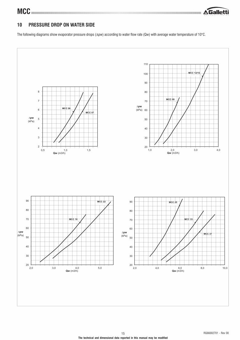
10 PRESSURE DROP ON WATER SIDE
The following diagrams show evaporator pressure drops (∆pw) according to water flow rate (Qw) with average water temperature of 10°C.
����
�
�
�
�
��� ���
����� �
��������
�
������
�����
�����
��
��
��
��
�
��� ���
����� �
��������
��
��
���
�����
���
������ ��
���
�����
��
��
��
��
�
��� ���
����� �
��������
��
��
���
������������
������
�����
��
��
��
��
�
��� ���
����� �
��������
��
��
���
�����
������
������
����

16RG66002701 - Rev 00
MCC
The technical and dimensional data reported in this manual may be modified
11 UNIT AVAILABLE PRESSURE HEAD
The following diagrams show availiable unit pressure head (Pu) according to water flow rate (Qw) with average water temperature of 10°C.
�����
��
��
��
��
�
��� ���
���� �
��������
��
�����
������
�����
��
��
���
���
���
��� ���
���� �
��������
���
���
���
���
������ �������
�����
��
��
��
���
���
��� ���
���� �
��������
���
���
���
������������
�����
�
��
��
���
���
��� ���
���� �
��������
���
���
���
�����
������
����
���
���
������

17 RG66002701 - Rev 00
The technical and dimensional data reported in this manual may be modified
MCC
12 WATER CIRCUIT
When setting up the water circuit of the unit, it is advisable to follow the directionsbelow and in any case comply with local or national regulations.
Connect the pipes to the chiller using flexible couplings to prevent thetransmission of vibrations and to compensate thermal expansions.It is recommended to install the following components on the pipes:- Temperature and pressure indicators for routine maintenance and monitoring
of the unit. Checking the pressure on the water side will enable you to verifywhether the expansion tank is working efficiently and to promptly detect anywater leaks within the equipment.
- Traps on incoming and outgoing pipes for temperature measurements,which can provide a direct reading of the operating temperatures.
- Regulating valves (gate valves) for isolating the unit from the water circuit.- Metal mesh filter (incoming pipes), with a mesh not to exceed 1 mm, to
protect the exchanger from scale or impurities present in the pipes.- Air vent valves, to be placed at the highest points of the water circuit for the
purpose of bleeding air. (The internal pipes of the unit are fitted with smallair vent valves for bleeding the unit itself: this operation may only be carriedout when the unit is disconnected from the power supply).
- Drainage valve and, where necessary, a drainage tank for emptying out theequipment for maintenance purposes or when the unit is taken out of serviceat the end of the season. (A 1" drainage valve is provided on the optionalinertial storage reservoir: this operation may only be carried out when the unitis disconnected from the power supply).
GA Vibration-damping coupling (not supplied)�P Differential pressure switchEV Evaporator (R407C/water exchanger)MA Water pressure gaugeP Water pumpRR Automatic filling deviceRS Drain manifoldVAS Automatic air vent valveSIA Inertial water storage reservoirVE Expansion tankVS Safety valve
MCC - CB
from the system
to the system
�� ��
��
��
��
��
�� ��
��
��
��
��
���
��
��
��
��
��
from the system
to the system
It is of fundamental importance that the incoming water supply is hooked upto the connection marked "Water Inlet"Otherwise the evaporator would be exposed to the risk of freezing since theantifreeze thermostat would not be able to perform its function; moreover thereverse cycle would not be respected in the cooling mode, resulting in additionalrisks of malfunctioning.
The dimensions and position of plumbing connections are shown in thedimension tables at the back of the manual.
The water circuit must be set up in such a way as to guarantee that the nominalflow rate of the water supplied to the evaporator remains constant (+/- 15%)in all operating conditions.
A standard feature of MCC units is a device for controlling the flow rate (flowswitch or differential pressure switch) in the water circuit in the immediatevicinity of the evaporator.
�� ��
��
��
�
��
��
�����
��
MCC - CP
MCC - CS
from the system
to the system
18RG66002701 - Rev 00
MCC
The technical and dimensional data reported in this manual may be modified
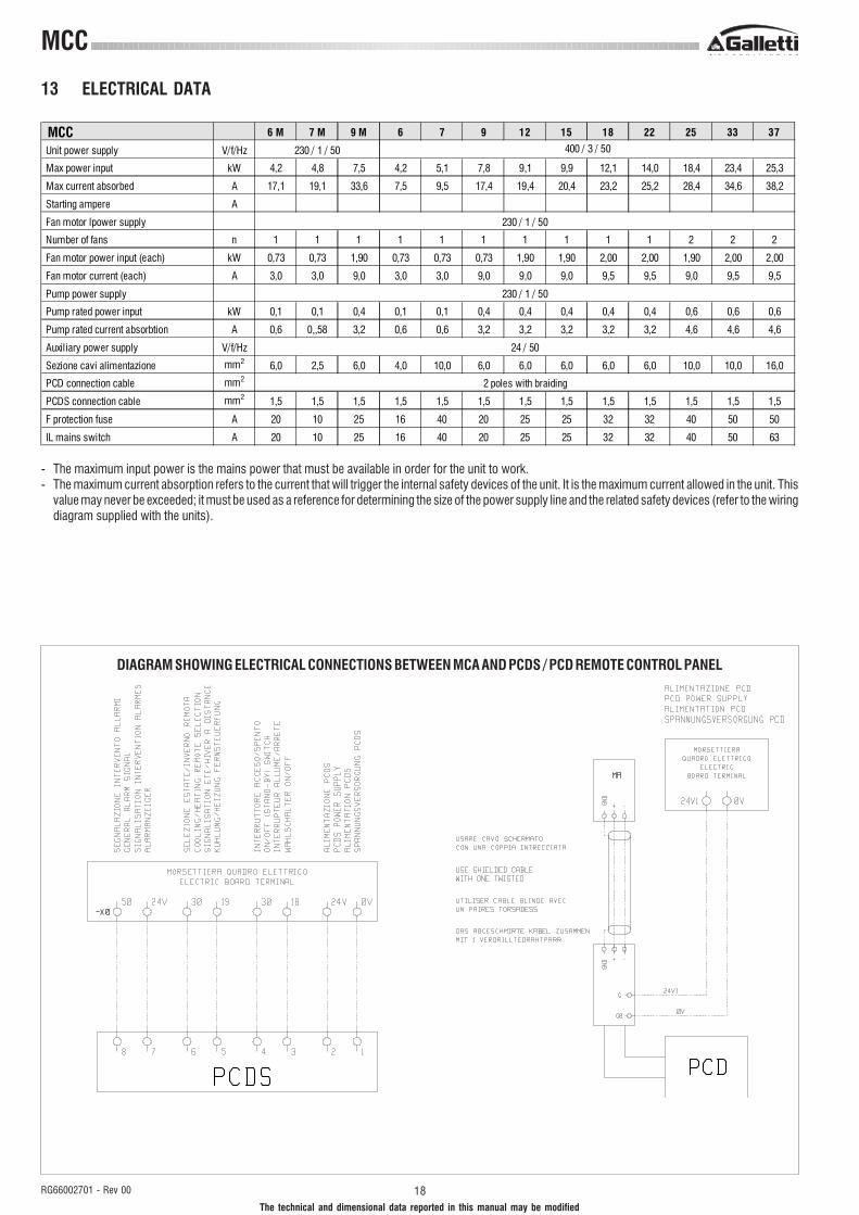
13 ELECTRICAL DATA
- The maximum input power is the mains power that must be available in order for the unit to work.- The maximum current absorption refers to the current that will trigger the internal safety devices of the unit. It is the maximum current allowed in the unit. This
value may never be exceeded; it must be used as a reference for determining the size of the power supply line and the related safety devices (refer to the wiringdiagram supplied with the units).
DIAGRAM SHOWING ELECTRICAL CONNECTIONS BETWEEN MCA AND PCDS / PCD REMOTE CONTROL PANEL
MCC 6 M 7 M 9 M 6 7 9 12 15 18 22 25 33 37
Unit power supply V/f/Hz
Max power input kW 4,2 4,8 7,5 4,2 5,1 7,8 9,1 9,9 12,1 14,0 18,4 23,4 25,3
Max current absorbed A 17,1 19,1 33,6 7,5 9,5 17,4 19,4 20,4 23,2 25,2 28,4 34,6 38,2
Starting ampere A
Fan motor lpower supply
Number of fans n 1 1 1 1 1 1 1 1 1 1 2 2 2
Fan motor power input (each) kW 0,73 0,73 1,90 0,73 0,73 0,73 1,90 1,90 2,00 2,00 1,90 2,00 2,00
Fan motor current (each) A 3,0 3,0 9,0 3,0 3,0 9,0 9,0 9,0 9,5 9,5 9,0 9,5 9,5
Pump power supply
Pump rated power input kW 0,1 0,1 0,4 0,1 0,1 0,4 0,4 0,4 0,4 0,4 0,6 0,6 0,6
Pump rated current absorbtion A 0,6 0,,58 3,2 0,6 0,6 3,2 3,2 3,2 3,2 3,2 4,6 4,6 4,6
Auxiliary power supply V/f/Hz
Sezione cavi alimentazione mm2 6,0 2,5 6,0 4,0 10,0 6,0 6,0 6,0 6,0 6,0 10,0 10,0 16,0
PCD connection cable mm2
PCDS connection cable mm2 1,5 1,5 1,5 1,5 1,5 1,5 1,5 1,5 1,5 1,5 1,5 1,5 1,5
F protection fuse A 20 10 25 16 40 20 25 25 32 32 40 50 50
IL mains switch A 20 10 25 16 40 20 25 25 32 32 40 50 63
24 / 50
230 / 1 / 50 400 / 3 / 50
230 / 1 / 50
230 / 1 / 50
2 poles with braiding
19 RG66002701 - Rev 00
The technical and dimensional data reported in this manual may be modified
MCC
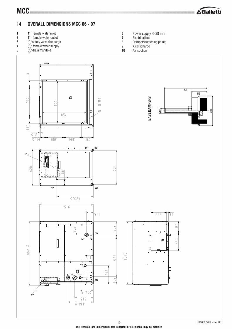
14 OVERALL DIMENSIONS MCC 06 - 07
1 1" female water inlet2 1" female water outlet3 1/
2" safety valve discharge
4 1/2" female water supply
5 1/2" drain manifold
6 Power supply Φ 28 mm7 Electrical box8 Dampers fastening points9 Air discharge10 Air suction
BASE
DAM
PERS

20RG66002701 - Rev 00
MCC
The technical and dimensional data reported in this manual may be modified
14 OVERALL DIMENSIONS MCC 09 - 15
1 1 1/4" female water inlet
2 1 1/4" female water outlet
3 1/2" safety valve discharge
4 1/2" female water supply
5 1/2" drain manifold
6 Power supply Φ 28 mm7 Electrical box8 Dampers fastening points9 Air discharge10 Air suction
BASE
DAM
PERS

21 RG66002701 - Rev 00
The technical and dimensional data reported in this manual may be modified
MCC
14 OVERALL DIMENSIONS MCC 18 - 22
1 1 1/4" female water inlet
2 1 1/4" female water outlet
3 1/2" safety valve discharge
4 1/2" female water supply
5 1/2" drain manifold
6 Power supply Φ 28 mm7 Electrical box8 Dampers fastening points9 Air discharge10 Air suction
BASE
DAM
PERS

22RG66002701 - Rev 00
MCC
The technical and dimensional data reported in this manual may be modified
14 OVERALL DIMENSIONS MCC 25 - 37
1 1 1/4" female water inlet
2 1 1/4" female water outlet
3 1/2" safety valve discharge
4 1/2" female water supply
5 1/2" drain manifold
6 Power supply Φ 28 mm7 Electrical box8 Dampers fastening points9 Air discharge10 Air suction
BASE
DAM
PERS

23 RG66002701 - Rev 00
The technical and dimensional data reported in this manual may be modified
MCC
15 INSTALLATION CLEARANCE REQUIREMENTS
To guarantee the proper functioning of the unit and access for maintenance purposes, it is necessary to comply with the minimum installation clearancerequirements shown in figures 1 and 2.Verify that there are no obstacoles in front of the fans air outlet.Avoid any and all situations of backflow of hot air between air outlet and inlet of the unit. If even only one of the above conditions is not fulfilled, please contactthe manufacturer to check for feasibility.
�
�
�� ����������������������� ������
�� ������������� �� ������
���������� �����������
���� ������� �������� ��������
����!/�""
���������� �����������
�� ����������������������� ������
�� ������������� �� ������
���� ������� �������� ��������

24RG66002701 - Rev 00
MCC
The technical and dimensional data reported in this manual may be modified
������������ ���������������� �������� ����������������������������
������ �����
16 SITING
Water chillers and Heat pumps, MCC series, are air condensed units, designed for installation inside technical rooms. Discharge and/or intake ducts has to bemade and designed for the rated air flow and available static pressure, for each model. At same time any possible air bypass (between intake and discharge)due to wrong installation layout must be avoided. A typical installation with upper discharge is shown in picture 1.It is important to bear in mind the following aspects when choosing the best site for installing the unit:- size and origin of water pipes;- location of the power supply;- solidity of the supporting surface;- site the unit so to avoid dominant winds can influence the air flow of the unit (ex. cold winds on the condensing coil, during winter in cooling mode, could
alter the correct working of the condensing control);- Avoid installations that could create noise or vibration transmission along ducts or through the technical room structure. For this reason the adoption of vibration
insulation on the air discharge (options) and also vibration dampers (option) are recommended. When vibration dampers on the unit basement are installed,vibration insulators on the hydraulic connections are also strongly recommended.
- ensure adequate accessibility for maintenance or repairs (see section on "installation clearance requirements").
Note: heat pump units produce condensation while operating in the heating mode.
� �����������������
������ ���������� ���
� ��������������������������������
�������� ����� ��� ��
�� �!�������!���� ������������" ����� ���������� �������!�����#��� ������ ���
$ �%��� �����������&'��� ��%��� ���(��� ��������������������������
���������%� ������%�������� �
������&'���������������������%�����!�� ����������� ��!������!� �������
����� ����!������>
30cm