mcp19125 flyback battery charger user's...
TRANSCRIPT

2017 Microchip Technology Inc. DS50002541A
MCP19125 Flyback Battery Charger
Evaluation BoardUser’s Guide

DS50002541A-page 2 2017 Microchip Technology Inc.
Information contained in this publication regarding deviceapplications and the like is provided only for your convenienceand may be superseded by updates. It is your responsibility toensure that your application meets with your specifications.MICROCHIP MAKES NO REPRESENTATIONS ORWARRANTIES OF ANY KIND WHETHER EXPRESS ORIMPLIED, WRITTEN OR ORAL, STATUTORY OROTHERWISE, RELATED TO THE INFORMATION,INCLUDING BUT NOT LIMITED TO ITS CONDITION,QUALITY, PERFORMANCE, MERCHANTABILITY ORFITNESS FOR PURPOSE. Microchip disclaims all liabilityarising from this information and its use. Use of Microchipdevices in life support and/or safety applications is entirely atthe buyer’s risk, and the buyer agrees to defend, indemnify andhold harmless Microchip from any and all damages, claims,suits, or expenses resulting from such use. No licenses areconveyed, implicitly or otherwise, under any Microchipintellectual property rights unless otherwise stated.
Note the following details of the code protection feature on Microchip devices:
• Microchip products meet the specification contained in their particular Microchip Data Sheet.
• Microchip believes that its family of products is one of the most secure families of its kind on the market today, when used in the intended manner and under normal conditions.
• There are dishonest and possibly illegal methods used to breach the code protection feature. All of these methods, to our knowledge, require using the Microchip products in a manner outside the operating specifications contained in Microchip’s Data Sheets. Most likely, the person doing so is engaged in theft of intellectual property.
• Microchip is willing to work with the customer who is concerned about the integrity of their code.
• Neither Microchip nor any other semiconductor manufacturer can guarantee the security of their code. Code protection does not mean that we are guaranteeing the product as “unbreakable.”
Code protection is constantly evolving. We at Microchip are committed to continuously improving the code protection features of ourproducts. Attempts to break Microchip’s code protection feature may be a violation of the Digital Millennium Copyright Act. If such actsallow unauthorized access to your software or other copyrighted work, you may have a right to sue for relief under that Act.
Microchip received ISO/TS-16949:2009 certification for its worldwide headquarters, design and wafer fabrication facilities in Chandler and Tempe, Arizona; Gresham, Oregon and design centers in California and India. The Company’s quality system processes and procedures are for its PIC® MCUs and dsPIC® DSCs, KEELOQ® code hopping devices, Serial EEPROMs, microperipherals, nonvolatile memory and analog products. In addition, Microchip’s quality system for the design and manufacture of development systems is ISO 9001:2000 certified.
QUALITY MANAGEMENT SYSTEM CERTIFIED BY DNV
== ISO/TS 16949 ==
Trademarks
The Microchip name and logo, the Microchip logo, AnyRate, AVR, AVR logo, AVR Freaks, BeaconThings, BitCloud, CryptoMemory, CryptoRF, dsPIC, FlashFlex, flexPWR, Heldo, JukeBlox, KEELOQ, KEELOQ logo, Kleer, LANCheck, LINK MD, maXStylus, maXTouch, MediaLB, megaAVR, MOST, MOST logo, MPLAB, OptoLyzer, PIC, picoPower, PICSTART, PIC32 logo, Prochip Designer, QTouch, RightTouch, SAM-BA, SpyNIC, SST, SST Logo, SuperFlash, tinyAVR, UNI/O, and XMEGA are registered trademarks of Microchip Technology Incorporated in the U.S.A. and other countries.
ClockWorks, The Embedded Control Solutions Company, EtherSynch, Hyper Speed Control, HyperLight Load, IntelliMOS, mTouch, Precision Edge, and Quiet-Wire are registered trademarks of Microchip Technology Incorporated in the U.S.A.
Adjacent Key Suppression, AKS, Analog-for-the-Digital Age, Any Capacitor, AnyIn, AnyOut, BodyCom, chipKIT, chipKIT logo, CodeGuard, CryptoAuthentication, CryptoCompanion, CryptoController, dsPICDEM, dsPICDEM.net, Dynamic Average Matching, DAM, ECAN, EtherGREEN, In-Circuit Serial Programming, ICSP, Inter-Chip Connectivity, JitterBlocker, KleerNet, KleerNet logo, Mindi, MiWi, motorBench, MPASM, MPF, MPLAB Certified logo, MPLIB, MPLINK, MultiTRAK, NetDetach, Omniscient Code Generation, PICDEM, PICDEM.net, PICkit, PICtail, PureSilicon, QMatrix, RightTouch logo, REAL ICE, Ripple Blocker, SAM-ICE, Serial Quad I/O, SMART-I.S., SQI, SuperSwitcher, SuperSwitcher II, Total Endurance, TSHARC, USBCheck, VariSense, ViewSpan, WiperLock, Wireless DNA, and ZENA are trademarks of Microchip Technology Incorporated in the U.S.A. and other countries.
SQTP is a service mark of Microchip Technology Incorporated in the U.S.A.
Silicon Storage Technology is a registered trademark of Microchip Technology Inc. in other countries.
GestIC is a registered trademark of Microchip Technology Germany II GmbH & Co. KG, a subsidiary of Microchip Technology Inc., in other countries.
All other trademarks mentioned herein are property of their respective companies.
© 2017, Microchip Technology Incorporated, All Rights Reserved.
ISBN: 978-1-5224-2140-5

EU Declaration of Conformity This declaration of conformity is issued by the manufacturer. The development/evaluation tool is designed to be used for research and development in a laboratory environment. This development/evaluation tool is not a Finished Appliance, nor is it intended for incorporation into Finished Appliances that are made commercially available as single functional units to end users under EU EMC Directive 2004/108/EC and as supported by the European Commission's Guide for the EMC Directive 2004/108/EC (8th February 2010). This development/evaluation tool complies with EU RoHS2 Directive 2011/65/EU. This development/evaluation tool, when incorporating wireless and radio-telecom functionality, is in compliance with the essential requirement and other relevant provisions of the R&TTE Directive 1999/5/EC and the FCC rules as stated in the declaration of conformity provided in the module datasheet and the module product page available at www.microchip.com. For information regarding the exclusive, limited warranties applicable to Microchip products, please see Microchip’s standard terms and conditions of sale, which are printed on our sales documentation and available at www.microchip.com. Signed for and on behalf of Microchip Technology Inc. at Chandler, Arizona, USA.
Object of Declaration: MCP19125 Flyback Battery Charger Evaluation Board
2017 Microchip Technology Inc. DS50002541A-page 3

NOTES:
DS50002541A-page 4 2017 Microchip Technology Inc.

MCP19125 FLYBACK BATTERY CHARGER
EVALUATION BOARD USER’S GUIDE
Table of Contents
Preface ........................................................................................................................... 7Introduction............................................................................................................ 7
Document Layout .................................................................................................. 7
Conventions Used in This Guide........................................................................... 8
Recommended Reading........................................................................................ 9
The Microchip Website.......................................................................................... 9
Customer Support ................................................................................................. 9
Revision History .................................................................................................... 9
Chapter 1. Product Overview1.1 Introduction ................................................................................................... 10
1.2 MCP19125 Device Short Overview .............................................................. 10
1.3 What is the MCP19125 Flyback Battery Charger Evaluation Board? .......... 12
1.4 What the MCP19125 Flyback Battery Charger Evaluation Board Kit Contains ................................................................ 12
Chapter 2. Installation and Operation2.1 Board Features ............................................................................................. 14
2.2 Getting Started ............................................................................................. 152.2.1 Instruments and Tools ............................................................................... 15
2.2.2 Installation ................................................................................................. 15
Chapter 3. Graphical User Interface3.1 Running the MCP19125 Flyback Battery Charger Evaluation Board ........... 16
3.1.1 Setting up the GUI and the Board ............................................................. 16
3.1.2 Charge Configuration ................................................................................ 17
3.1.3 Running a Charge Profile .......................................................................... 18
3.1.4 Battery Chemistry Charge Profiles ............................................................ 20
3.2 Programming the MCP19125 Flyback Battery Charger Evaluation Board .................................................................................... 24
Appendix A. Schematic and LayoutsA.1 Introduction .................................................................................................. 26A.2 Board – Schematic 1 .................................................................................... 27A.3 Board – Schematic 2 .................................................................................... 28A.4 Board – Top Silk Layer ................................................................................ 29A.5 Board – Top Copper and Silk Layer ............................................................. 30A.6 Board – Top Copper .................................................................................... 31A.7 Board – Mid-Layer 1 .................................................................................... 32A.8 Board – Mid-Layer 2 .................................................................................... 33
2017 Microchip Technology Inc. DS50002541A-page 5

MCP19125 Flyback Battery Charger Evaluation Board User’s Guide
A.9 Board – Bottom Copper ............................................................................... 34A.10 Board – Bottom Cooper and Silk Layer ..................................................... 35A.11 Board – Bottom Silk Layer ......................................................................... 36
Appendix B. Bill of Materials (BOM) ...........................................................................38
Appendix C. Charge Profile Block Diagrams.............................................................42C.1 Introduction .................................................................................................. 42
Worldwide Sales and Service .....................................................................................58
DS50002541A-page 6 2017 Microchip Technology Inc.

MCP19125 FLYBACK BATTERY CHARGER
EVALUATION BOARD USER’S GUIDE
Preface
INTRODUCTION
This chapter contains general information that will be useful to know before using the MCP19125 Flyback Battery Charger Evaluation Board. Items discussed in this chapter include:
• Document Layout
• Conventions Used in This Guide
• Recommended Reading
• The Microchip WebSite
• Customer Support
• Revision History
DOCUMENT LAYOUT
This document describes how to use the MCP19125 Flyback Battery Charger Evaluation Board. The document is organized as follows:
• Chapter 1. “Product Overview” – Important information about the MCP19125 Flyback Battery Charger Evaluation Board.
• Chapter 2. “Installation and Operation” – Includes instructions on how to get started with MCP19125 Flyback Battery Charger Evaluation Board.
• Chapter 3. “Graphical User Interface” – Provides instructions on how to set up and use the Graphical User Interface (GUI).
• Appendix A. “Schematic and Layouts” – Shows the schematic and layout diagrams for the MCP19125 Flyback Battery Charger Evaluation Board.
• Appendix B. “Bill of Materials (BOM)” – Lists the parts used to build the MCP19125 Flyback Battery Charger Evaluation Board.
• Appendix C. “Charge Profile Block Diagrams”– Includes block diagrams showing the flow of logic that enable the MCP19125 to control the charge cycle for efficient battery charging.
NOTICE TO CUSTOMERS
All documentation becomes dated, and this manual is no exception. Microchip tools anddocumentation are constantly evolving to meet customer needs, so some actual dialogsand/or tool descriptions may differ from those in this document. Please refer to our website(www.microchip.com) to obtain the latest documentation available.
Documents are identified with a “DS” number. This number is located on the bottom of eachpage, in front of the page number. The numbering convention for the DS number is“DSXXXXXXXXA”, where “XXXXXXXX” is the document number and “A” is the revision levelof the document.
For the most up-to-date information on development tools, see the MPLAB® IDE online help.Select the Help menu, and then Topics to open a list of available online help files.
2017 Microchip Technology Inc. DS50002541A-page 7

MCP19125 Flyback Battery Charger Evaluation Board User’s Guide
CONVENTIONS USED IN THIS GUIDE
This manual uses the following documentation conventions:
DOCUMENTATION CONVENTIONS
Description Represents Examples
Arial font:
Italic characters Referenced books MPLAB® IDE User’s Guide
Emphasized text ...is the only compiler...
Initial caps A window the Output window
A dialog the Settings dialog
A menu selection select Enable Programmer
Quotes A field name in a window or dialog
“Save project before build”
Underlined, Italic text with right angle bracket
A menu path File>Save
Bold characters A dialog button Click OK
A tab Click the Power tab
N‘Rnnnn A number in verilog format, where N is the total number of digits, R is the radix and n is a digit.
4‘b0010, 2‘hF1
Text in angle brackets < > A key on the keyboard Press <Enter>, <F1>
Courier New font:
Plain Courier New Sample source code #define START
Filenames autoexec.bat
File paths c:\mcc18\h
Keywords _asm, _endasm, static
Command-line options -Opa+, -Opa-
Bit values 0, 1
Constants 0xFF, ‘A’
Italic Courier New A variable argument file.o, where file can be any valid filename
Square brackets [ ] Optional arguments mcc18 [options] file [options]
Curly brackets and pipe character: { | }
Choice of mutually exclusive arguments; an OR selection
errorlevel {0|1}
Ellipses... Replaces repeated text var_name [, var_name...]
Represents code supplied by user
void main (void){ ...}
DS50002541A-page 8 2017 Microchip Technology Inc.

Preface
RECOMMENDED READING
This user's guide describes how to use MCP19125 Flyback Battery Charger EvaluationBoard. The following Microchip document is available and recommended as asupplemental reference resource:
• MCP19125 Data Sheet – “Digitally Enhanced Power Analog Synchronous Low-Side Dual Loop PWM Controller” (DS20005619)
THE MICROCHIP WEBSITE
Microchip provides online support via our website at www.microchip.com. This websiteis used as a means to make files and information easily available to customers.Accessible by using your favorite Internet browser, the website contains the followinginformation:
• Product Support – Data sheets and errata, application notes and sampleprograms, design resources, user’s guides and hardware support documents,latest software releases and archived software
• General Technical Support – Frequently Asked Questions (FAQs), technicalsupport requests, online discussion groups, Microchip consultant programmember listing
• Business of Microchip – Product selector and ordering guides, latest Microchip press releases, listing of seminars and events, listings of Microchip sales offices, distributors and factory representatives.
CUSTOMER SUPPORT
Users of Microchip products can receive assistance through several channels:
• Distributor or Representative
• Local Sales Office
• Field Application Engineer (FAE)
• Technical Support
Customers should contact their distributor, representative or field application engineer(FAE) for support. Local sales offices are also available to help customers. A listing ofsales offices and locations is included in the back of this document.
Technical support is available through the website at:
http://www.microchip.com/support.
REVISION HISTORY
Revision A (September 2017)
• Original release of this document.
2017 Microchip Technology Inc. DS50002541A-page 9
MCP19125 FLYBACK BATTERY CHARGER
EVALUATION BOARD USER’S GUIDE
Chapter 1. Product Overview
1.1 INTRODUCTION
This provides an overview of the MCP19125 Flyback Battery Charger Evaluation Board and covers the following topics:
• MCP19125 Device Short Overview
• What is the MCP19125 Flyback Battery Charger Evaluation Board?
• What the MCP19125 Flyback Battery Charger Evaluation Board Kit Contains
1.2 MCP19125 DEVICE SHORT OVERVIEW
The MCP19125 is a highly-integrated, mixed-signal low-side synchronous Pulse Width Modulation (PWM) controller that operates from 4.5V to 42V. This device features individual analog PWM control loops for both current regulation or voltage regulation. These features, along with an integrated microcontroller core, make this an ideal device for battery charging applications, LED lighting systems, and any other low-side switch PWM applications. Complete customization of device operating parameters, start-up or shutdown profiles, protection levels, and fault handling procedures are accomplished by setting digital registers using Microchip’s MPLAB® X Integrated Development Environment software and one of Microchip’s many in-circuit debugger and device programmers.
The MCP19125 features integrated low-side synchronous drivers, an internal linear regulator, and 4k word nonvolatile memory, all in a space-saving 28-pin 5 mm x 5 mm QFN package.
2017 Microchip Technology Inc. DS50002541A-page 10

MCP19125 Flyback Battery Charger Evaluation Board User’s Guide
Refer to Figure 1-1 to view the MCP19125 Flyback Battery Charger Evaluation Board Overview.
FIGURE 1-1: MCP19125 Flyback Battery Charger Evaluation Board Overview.
DS50002541A-page 11 2017 Microchip Technology Inc.

Product Overview
1.3 WHAT IS THE MCP19125 FLYBACK BATTERY CHARGER EVALUATION BOARD?
The MCP19125 Flyback Battery Charger Evaluation Board demonstrates how the MCP19125 device operates in a battery charging application utilizing a synchronous flyback topology. It is configured to regulate the amount of charge current, and the type of charging, while simultaneously reading the state of the battery to change between operation modes for optimized charge profiles. The MCP19125 Flyback Battery Charger Evaluation Board was designed to operate with a wide input voltage range of 4.5 V to 42V. Nearly all operational and control system parameters are programmable by utilizing the integrated PIC® microcontroller.
The board comes preprogrammed with firmware designed to operate with a downloadable Graphical User Interface (GUI). MPLAB® X Integrated Development Environment (IDE) software can be used to download the user-defined firmware, thus tailoring it to the user’s specific application. The evaluation board contains headers for In-Circuit Serial Programming (ICSP), as well as I2C communication.
The MCP19125 Flyback Battery Charger Evaluation Board firmware implements an Synchronous Serial Port (SSP) module process derived from the I2C specification to allow the MCP19125 to communicate with the GUI through a PICkit™ Serial Analyzer. MPLAB® X IDE, MPLAB® XC8 Complier toolchain, the MCP19XXX Multi-Chemistry Multi-Topology Battery Charger GUI and the MCP19125 Flyback Battery Charger Evaluation Board firmware are available for download from the Microchip website. See Chapter 3. “Graphical User Interface” for details.
1.4 WHAT THE MCP19125 FLYBACK BATTERY CHARGER EVALUATION BOARD KIT CONTAINS
This MCP19125 Flyback Battery Charger Evaluation Board kit includes the following:
• MCP19125 Flyback Battery Charger Evaluation Board (ADM00745)
• Important Information Sheet.
2017 Microchip Technology Inc. DS50002541A-page 12

MCP19125 Flyback Battery Charger Evaluation Board User’s Guide
NOTES:
DS50002541A-page 13 2017 Microchip Technology Inc.

MCP19125 FLYBACK BATTERY CHARGER
EVALUATION BOARD USER’S GUIDE
Chapter 2. Installation and Operation
2.1 BOARD FEATURES
The MCP19125 Flyback Battery Charger Evaluation Board can be used to charge Lithium-Ion (Li-Ion) batteries of two-four cells, Nickel Metal-Hydride (NiMH) batteries of two-seven cells and Valve-Regulated Lead-Acid (VRLA) batteries of up to three or six cells. The board uses the MCP19125 digitally enhanced PWM controller to generate the charge algorithms for the various battery types. The board can run in Rapid Charge Current mode for NiMH batteries, as well as Constant-Current/Constant-Voltage mode for Li-Ion batteries. The MCP19125 Flyback Battery Charger Evaluation Board also has two charge configurations for VRLA batteries, which can be charged in both Step Charge and Constant-Current modes.
MCP19125 Flyback Battery Charger Evaluation Board was developed to provide an intelligent, compact, and highly efficient solution demonstrating the MCP19125 as a battery charger utilizing a synchronous flyback topology. The dual control loops of the MCP19125 device allow monitoring and regulation of the charge current and battery pack voltage. The battery charger board also provides several status and fault indications for various states of the board. Furthermore, the MCP19125 is programmed to read the temperature of the battery pack if a temperature sensing resistor is available, and react to temperature changes.
Component LD1 blinks at a rate of 50 ms on, 1.75s off when the charger is in Standby mode, and a rate of 0.75s on, 0.75s off when the charger is charging. Moreover, the board detects the presence or removal of a battery pack. The board has the capability to connect to both the PICkit™ 3 In-Circuit Debugger/Programmer for reprogramming and the PICkit ™Serial Analyzer to operate in conjunction with the GUI. Normally, the PICkit™ Serial Analyzer is used to configure the charge cycle and change parameters.
The MCP19125 Flyback Battery Charger Evaluation Board is fully assembled, programmed, and tested to evaluate and demonstrate the MCP19125 operating performance in a digitally-controlled “smart battery-charging” application for various common battery chemistries.
2017 Microchip Technology Inc. DS50002541A-page 14

MCP19125 Flyback Battery Charger Evaluation Board User’s Guide
2.2 GETTING STARTEDThe MCP19125 requires a computer with Microsoft® Windows® XP/7/8 operating system and a USB 2.0 port. To run the software, follow the steps described in this section.
2.2.1 Instruments and Tools
• Adjustable DC power supply with 0V-24V voltage range
• MCP19125 Flyback Battery Charger Evaluation Board
• MCP19XXX Multi-Chemistry Multi-Topoligy Battery Charger GUI
• PICkit™ Serial Analyzer
• Battery Pack
2.2.2 Installation
Follow the steps below to download and install the MCP19125 firmware and GUI:
1. Download the MCP19125 Flyback Battery Charger Evaluation Board Firmware and GUI archive from the Microchip website at http://www.microchip.com/wwwproducts/en/MCP19125.
2. After downloading and unzipping the archive, open the GUI folder and locate the setup.exe file.
3. Double-click the file. In the Application Install - Security Warning dialog box, press the Install button.
4. Once the installation is complete, the GUI will appear on the screen, as shown in Figure 2-1:
FIGURE 2-1: MCP19XXX Multi-Chemistry Multi-Topoligy Battery Charger GUI.
DS50002541A-page 15 2017 Microchip Technology Inc.
MCP19125 FLYBACK BATTERY CHARGER
EVALUATION BOARD USER’S GUIDE
Chapter 3. Graphical User Interface
3.1 RUNNING THE MCP19125 FLYBACK BATTERY CHARGER EVALUATION BOARD
3.1.1 Setting up the GUI and the Board
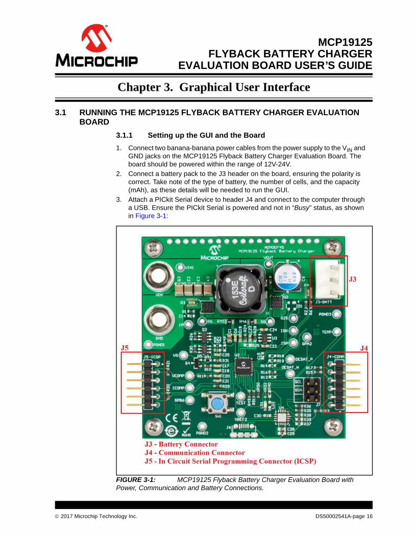
1. Connect two banana-banana power cables from the power supply to the VIN and GND jacks on the MCP19125 Flyback Battery Charger Evaluation Board. The board should be powered within the range of 12V-24V.
2. Connect a battery pack to the J3 header on the board, ensuring the polarity is correct. Take note of the type of battery, the number of cells, and the capacity (mAh), as these details will be needed to run the GUI.
3. Attach a PICkit Serial device to header J4 and connect to the computer through a USB. Ensure the PICkit Serial is powered and not in “Busy” status, as shown in Figure 3-1:
FIGURE 3-1: MCP19125 Flyback Battery Charger Evaluation Board with Power, Communication and Battery Connections.
2017 Microchip Technology Inc. DS50002541A-page 16

MCP19125 Flyback Battery Charger Evaluation Board User’s Guide
3.1.2 Charge Configuration
1. The MCP19XXX Multi-Chemistry Multi-Topology Battery Charger GUI can be used for two different battery charger evaluation boards; ADM00513 - MCP19111 Buck Topology Battery Charger, and ADM00745 - MCP19125 Flyback Topology Battery Charger. Select ADM00745 on the Evaluation Board tab.
2. With the board powered, select a battery chemistry from the drop down menu of the Configure tab. The different chemistries require different charge profiles. Selecting a chemistry lets the GUI provide preset values for various charge parameters. Selecting a chemistry also blocks off certain parameters that can be controlled by the user to ensure safe and efficient charging.
3. Select a charge configuration based on the type of battery and charging rate. These parameters can also be changed in the Configure tab of the GUI.
FIGURE 3-2: The GUI Configure Tab with Available Battery Chemistries.
4. If a battery has a thermistor, the user can select the With Thermister check box to allow the MCP19125 to read temperature values, which are displayed numerically as well as graphed real-time in the Profile tab.
5. When the user has entered the desired parameters into the GUI, the Write Configuration button must be pressed to write the profile into the MCP19125’s firmware. A Read Configuration button is also provided, which will read the current charge configuration from the firmware and load it into the GUI. If no configuration has been previously written, an error message is displayed.
DS50002541A-page 17 2017 Microchip Technology Inc.

Graphical User Interface
3.1.3 Running a Charge Profile
Once the user has ensured the battery charger board is powered, programmed and configured properly, a charge profile can be defined. By selecting the Profile tab, the user can control running the charge profile and monitoring the charge status. At the top of the tab, the user can view the instantaneous values of the pack voltage, pack current, input voltage, and state of the charger.
At all times, the user can see whether the battery pack is charging or not. The battery charger board will also give error states, such as Over-Temperature (OT), Under Threshold Input Voltage (UT), or Over Threshold Input Voltage (OVT). The charger will display Off if the user attempts to run a charge, but the charger board is not currently running.
TABLE 3-1: OTHER CONFIGURATION PARAMETERS
Parameter Description
Cell Voltage This parameter controls the rated voltage of each cell in the battery pack.
Precondition Cell Voltage
This parameter sets the voltage value at which the battery charger transitions from the Precondition Current mode to its Constant-Current mode. This transition is meant to protect the battery pack if the value is below the minimum value of the working voltage.
Termination Cell Voltage
This parameter controls the pack voltage value at which the battery charger ends the main charge phase and transitions to the Trickle Charge mode or turns off. This value is typically the maximum value of the specified working voltage range.
Rapid Charge/Charge CurrentThis parameter provides the current value applied to the battery pack by the charger during the main charging state. The charger implements either Rapid mode or Charge Current mode, depending on the battery chemistry selected.
Restoration/Precondition Current
For deeply discharged batteries, a small amount of restoration current is necessary to bring the battery pack voltage to a level that is safe to implement Rapid Charge Current mode or Charge Current mode. This parameter controls the current value applied during this stage of charging.
Trickle Charge Current
After the battery reaches termination cell voltage, the sudden decrease in current will lead to a drop in the pack voltage. The battery charger applies a trickle charge current controlled by this parameter for an allotted period of time to regulate the voltage at which the main charge cycle terminated.
Termination Current
For Li-Ion and VRLA CCCP chemistries that end their charge cycle in Constant-Voltage mode, the termination current parameter controls the current value at which the battery charger will end the charge cycle. The battery charger will slowly ramp down the charge current to this value and then turn off.
Number of CellsEnter the number of cells for the attached battery. The system uses this to calculate the termination voltage.
Rapid Charge TimeThis parameter sets the maximum time period during which the battery charger will run in the Rapid Charge mode.
Restoration Charge TimeThis parameter sets the maximum time period during which the battery charger will apply restoration current to the battery.
Maximum Temperature
A protection feature for the battery that is only active when the With Thermistor check box is selected with a NiMH charge profile. The parameter sets the maximum temperature in degrees Celsius (°C) that the battery can reach before the battery charger shuts off completely.
Minimum Temperature
A protection feature for the battery that is only active when the With Thermistor check box is selected. The parameter sets the minimum temperature in degrees Celsius (°C) that the battery can drop before the battery charger shuts off completely.
2017 Microchip Technology Inc. DS50002541A-page 18

MCP19125 Flyback Battery Charger Evaluation Board User’s Guide
Note that the MCP19125 Flyback Battery Charger Evaluation Board is shipped already programmed. Unless the user programs it themselves, the Charge Configuration is the only necessary user input.
When the battery is successfully charging, the Charger State will read different states based on the type of battery that is being charged. Examples of different charge states include “Precondition”, “Constant-Current”, “Constant-Voltage”, “Rapid Charge”, “Trickle”, and “Off”.
Enabling the charge can be toggled by selecting the Start and Stop buttons. The graphs on the lower half of the tab display real-time voltage and current, as well as a temperature profile if the With Thermistor check box was selected in the Configure tab. The GUI allows for the reporting of the various measured values in real time, so that the user can monitor if charge current and voltage are regulating correctly. The charge current limitations are defined by the following values:
• Minimum 0.1A
• Maximum 1A
FIGURE 3-3: A Full Charge Profile.
DS50002541A-page 19 2017 Microchip Technology Inc.

Graphical User Interface
3.1.4 Battery Chemistry Charge ProfilesFigure 3-3 – Figure 3-6 show examples of charge profiles.
FIGURE 3-4: Charge Profile for NiMH Battery Pack (7-cell, 1.00A Charge Current).
Charging
Completed Charge Cycle
2017 Microchip Technology Inc. DS50002541A-page 20

MCP19125 Flyback Battery Charger Evaluation Board User’s Guide
FIGURE 3-5: Charge Profile for Li-Ion Battery Pack (4-Cell, 1.00A Charge Current).
Charging
Completed Charge Cycle
DS50002541A-page 21 2017 Microchip Technology Inc.

Graphical User Interface
FIGURE 3-6: VRLA Step Charge Profile (6-Cell, 1.00A Charge Current).
Charging
Completed Charge Cycle
2017 Microchip Technology Inc. DS50002541A-page 22

MCP19125 Flyback Battery Charger Evaluation Board User’s Guide
FIGURE 3-7: VRLA CCCP Charge Profile (6-Cell, 1.00A Charge Current).
Charging
Completed Charge Cycle
DS50002541A-page 23 2017 Microchip Technology Inc.

Graphical User Interface
3.2 PROGRAMMING THE MCP19125 FLYBACK BATTERY CHARGER EVALUATION BOARD
The MCP19125 Flyback Battery Charger Evaluation Board comes with a preprogrammed firmware installed. The following tools are required to reprogram the device:
• MPLAB X Integrated Development System (IDE) (Version 2.05 or later)
• MPLAB XC8 Compiler (Version 1.3 or later)
• MCP19125 Flyback Battery Charger Evaluation Board Firmware
• MCP19125 Flyback Battery Charger Evaluation Board
• PICkit 3 In-Circuit Debugger/Programmer
Follow the steps below to install all necessary software and start reprogramming the MCP19125 device:
1. If MPLAB X IDE is already installed, go to Step 2. If not, download MPLAB X IDE from www.microchip.com/mplabx and follow the MPLAB X IDE installation instructions.
2. If an XC8 compatible compiler or an equivalent is already installed in MPLAB X IDE, go to Step 3. If not, a free version of Microchip’s XC8 is available for download on www.microchip.com/mplabxc. The XC8 user guide, installation instructions and download links are available on this page.
3. Download the MCP19125 Flyback Battery Charger Evaluation Board Firmware archive (*.zip) from www.microchip.com/mcp19125 under “Documentation & Software”.
4. Unzip the MCP19125 Flyback Battery Charger Evaluation Board Firmware archive. Place the MCP19125BatteryCharger.X project folder in the desired location.
5. Power up the MCP19125 Flyback Battery Charger Evaluation Board.
6. Connect the PICkit 3 In-Circuit Debugger to the MCP19125 Flyback Battery Charger Evaluation Board via the 6-pin connector, J5.
7. Open MPLAB X IDE to load the MCP19125 Flyback Battery Charger Evaluation Board Firmware. From the File menu, select “Open Project...”
8. Browse for the location of the extracted firmware. Select “MCP19125 Battery-Charger.X” from the list, then check the “Open as Main Project” option. Click on the Open Project button to complete loading the file.
Once the project is opened, click on the Make and Program Device Main Project button on the toolbar to program the device. Wait until the programming process is complete.
2017 Microchip Technology Inc. DS50002541A-page 24

MCP19125 Flyback Battery Charger Evaluation Board User’s Guide
NOTES:
DS50002541A-page 25 2017 Microchip Technology Inc.

MCP19125 FLYBACK BATTERY CHARGER
EVALUATION BOARD USER’S GUIDE
Appendix A. Schematic and Layouts
A.1 INTRODUCTION
This appendix contains the following schematics and layouts for the MCP19125 Flyback Battery Charger Evaluation Board:
• Board – Schematic 1
• Board – Schematic 2
• Board – Top Copper and Silk Layer
• Board – Top Copper
• Board – Mid-Layer 1
• Board – Mid-Layer 2
• Board – Bottom Copper
• Board – Bottom Cooper and Silk Layer
• Board – Bottom Silk Layer
2017 Microchip Technology Inc. DS50002541A-page 26

MC
P19125 F
lyback B
attery Ch
arger E
valuatio
n B
oard
User’s G
uid
e
DS
50
00
25
41
A-p
ag
e 2
7
20
17
Micro
chip
Te
chn
olo
gy In
c.
1000pF50V0603
C25
SW1
VOUT
GND
GND
S
TP13
T
VS
0603DNPC7
1210DNPC10
1210DNPC11
1210DNPC12
GND
5.1VD2
0603DNP
R23
P2
100k06030.1%
R27
3
2
4
Q3B
1
5
6
Q3A
30k06035%
R33
15k06035%
R26
3
12
Q4SW2
TP3
TEMP
VDD
VOUT
GND
HDR-3.96 Male 1x3
1123
J3
10k
0603 1%
R7
3
2
4
Q5B
15k06035%
R30
SW3 1
5
6
Q5A
5.1VD5
30k06035%
R47
0603DNP
R48
10k0603
5%
R4910k0603
5%
R5010k0603
5%
R51
GND
SW1SW2SW3
15k06030.1%
R31
22.6k06030.1%
R41
120uF50VE
C8
UT
TEMP
VS
A.2 BOARD – SCHEMATIC 1
10uF50V1210
C2 10uF50V1210
C3 0.1uF50V0603
C6
4.7uF16V0603
C19
0.05R06121%
R3
0R
0603R6
0R
0603R2
16V0603
DNPC15
1.5k
0603 1%
R10
GND
VS
ISPISN
ICSPCLK
SW1
TEST_ENICSPDAT
GPA2TEMP
TEST_OUT
DESAT_N
SDRVPDRV
IP
PDRV
IP
1uF16V0603DNP
C14
SDRV
GND
ISP
ISN
VIN
DESAT_P
Q2S
Q2D
VIN
GND
REDLD1
GND
Q2
TP15
VINVDD
VDR
VDD
VOUT VOU
GND
0R0603
R1TP6
TP16
TP14
TP17
TP4
TP7
TP11
TP12
0.1R06121%
R4
GND
TP22
SW2GPB6
VCOMPICOMP
1J1
1J2
1uF50V0805
C1 4.7uF50V1210
C4 4.7uF50V1210
C5
MCP19125
GPA0/AN0/TEST_OUT1
GPA1/AN1/CLKPIN2
GPA2/AN2/T0CKI/INT3
GPA3/AN35
GPB4/AN5/ICSPDAT 4
GPA7/SCL6
GPA5/MCLR/TEST_EN8
GPA6/CCD7
DESAT_N 11DESAT_P 12
ISP 13
ISN 14
IP 15
AGND16
PGND17
SDRV 18PDRV 19
VDR20
VDD21 VIN 22
VS 23
VCOMP 24
ICOMP 25
GPB1/AN4/VREF2 26
EP29
GPB7_CCD 9
GPB0/SDA 10
GPB5/AN6/ICSPCLK 27
GPB6/AN7 28
U2
TP1
TP9
TP8
T
TP10
GPB0/SDA
GPA7/SCL
DNPD4DNPD3 22R
1206 1%
R42
680pF100V0805
C3122R12061%
R43
680pF100V0805
C32
1206
DNPR44
100V 0805
DNPC33
PGATE SGATE
0R 0805
R45
0R 0805
R46
PGATE
SGATE
SW3
910pF
50V 0603
C18
15uH
13
X1A
24
390R
0603 1%
R110.068uF
25V 0603
C20
10000pF
50V 0603
C21
10000pF
50V 0603
C17
41,2,3
5,6,7,8Q1
41,2,3
5,6,7,8Q2
1k06035%
R22
PG
VIN
VO
GND
Q2S
SG
ISN
ISP
VCOMP
ICOMP
VREF2
TEST_OUT
IP
GND
VIN

Sc
he
ma
tic a
nd
La
yo
uts
2
01
7 M
icroch
ip T
ech
no
log
y Inc.
DS
50
00
25
41
A-p
ag
e 2
8
A.
LABEL Need Help Small
LABEL
GND
VBUS
50V0603
DNPC27
USB2.0 MICRO-B FEMALEDNP
ID4
VBUS1
GND5
D-2
D+3
0
J6VBUS
4.7k0603
5%
R354.7k06035%
R36
SDASCL
GND
HDR-2.54 Male 2x3
1123456
J7
USBD_PUSBD_N
Phillips Screw 1/4"
SCR2
Phillips Screw 1/4"
SCR4
Phillips Screw 1/4"
SCR1
Phillips Screw 1/4"
SCR3
06035%
DNPR34
-40 x 1/2
3 BOARD – SCHEMATIC 2
1uF25V0603
C22
4.7uF16V0603
C23
0R0603
R24
3.92k06031%
DNP
R13
BAV23,215
DNPD1A
BAV23,215
DNPD1B
VDD
Q2DDESAT_N0R0603
DNPR14
0R0603
DNPR19
VDD
3.92k06031%
DNP
R18
DESAT_P Q2S
TP18
TP19
VDD
GND
06035%
DNPR25
10R06035%
R28
GND
VDR
GND
TP20
10.2k06031%
R16
GND
TP21
GPB6
PTS645SM43SMTR92 LFS1 4
2 3
SW1
GND
10k0603
5%
R29
VDD
Q2S1k
0603 0.1%
DNPR8
1k
0603 0.1%DNP
R9
GND
220pF50V0603DNP
C13
GPA2
1uF16V0603
DNPC16
GND
VDD
TC1240A
VIN 1
GND2
C-3 SHDN 4
VOUT 5
C+6 VIN
GND
C- SHDN
VOUT
C+
U3
1uF25V0603
C26
4.7k
0603 5%
R32
MCP6071DNP
+A3
-A4
OUTA 1VSS
2
VDD
5
+A
-A
OUTAVSS
VDD
A
AS
D
U1
100k06030.1%
DNP
R5
1uF25V0603
C24
GPB0/SDAGPA7/SCL
GND
VBUS
SDASCLGND
GND
25V0603
DNPC30
GND
06035%
DNPR40
GND
USBD_PUSBD_N
50V0603
DNPC28
VBUS
MCP2221-I/ML
DNP
VDD16
GP01
GP12
RST3
UART RX4
UART TX5
GP26 GP3 7SDA 8SCL 9VUSB 10D- 11D+ 12VSS 13
EP 17
U4
16V0603
DNPC29
DNPLD2
GND
0R
0603
R15
0R
0603
R17
0R
0603
R12
10k0603
5%
R2010k06035%
R21
GND
VDD
VDD
TEST_EN
ICSPDATICSPCLK
GND
123456
J5
123456
J4
GPA7/SCL
GPB0/SDA
06035%
DNPR37
06035%
DNPR38
06035%
DNPR39
DESAT_N
DESAT_P
GPA2
GPB6
STAND-OFF 4
STANDOFF4
STAND-OFF 4-40 x 1/2
STANDOFF3
STAND-OFF 4-40 x 1/2
STANDOFF2
STAND-OFF 4-40 x 1/2
STANDOFF1

MCP19125 Flyback Battery Charger Evaluation Board User’s Guide
A.4 BOARD – TOP SILK LAYER
DS50002541A-page 29 2017 Microchip Technology Inc.

Schematic and Layouts
A.5 BOARD – TOP COPPER AND SILK LAYER
2017 Microchip Technology Inc. DS50002541A-page 30

MCP19125 Flyback Battery Charger Evaluation Board User’s Guide
A.6 BOARD – TOP COPPER
DS50002541A-page 31 2017 Microchip Technology Inc.
Schematic and Layouts
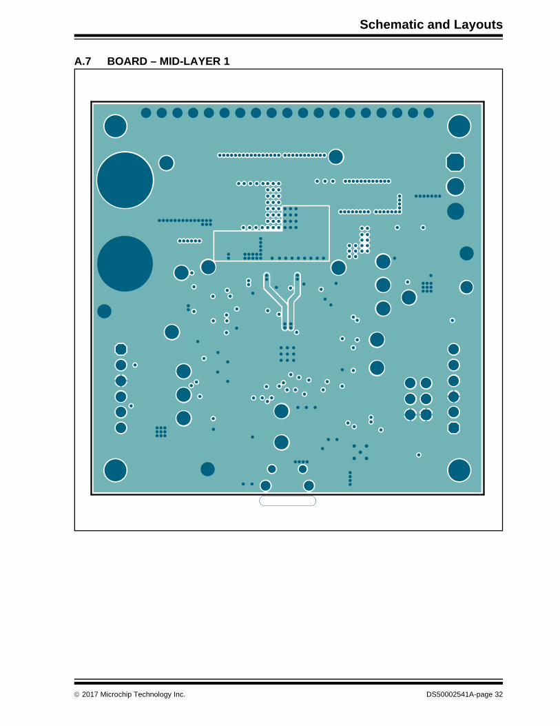
A.7 BOARD – MID-LAYER 1
2017 Microchip Technology Inc. DS50002541A-page 32

MCP19125 Flyback Battery Charger Evaluation Board User’s Guide
A.8 BOARD – MID-LAYER 2
DS50002541A-page 33 2017 Microchip Technology Inc.

Schematic and Layouts
A.9 BOARD – BOTTOM COPPER
2017 Microchip Technology Inc. DS50002541A-page 34

MCP19125 Flyback Battery Charger Evaluation Board User’s Guide
A.10 BOARD – BOTTOM COOPER AND SILK LAYER
DS50002541A-page 35 2017 Microchip Technology Inc.

Schematic and Layouts
A.11 BOARD – BOTTOM SILK LAYER
2017 Microchip Technology Inc. DS50002541A-page 36

MCP19125 Flyback Battery Charger Evaluation Board User’s Guide
NOTES:
DS50002541A-page 37 2017 Microchip Technology Inc.

MCP19125 FLYBACK BATTERY CHARGER
EVALUATION BOARD USER’S GUIDE
Appendix B. Bill of Materials (BOM)
TABLE B-1: BILL OF MATERIALS (BOM)
Qty. Reference Description Manufacturer Part Number
1 C1 Cap. cer. 1 µF 50V 10% X7R SMD 0805 Murata Electronics North America, Inc.
GRM21BR71H105KA12L
2 C2, C3 Cap. cer. 10 µF 50V 20% X7S SMD 1210 TDK Corporation C3225X7S1H106M
2 C4, C5 Cap. cer. 4.7 µF 50V 10% X7R SMD 1210 Murata Electronics North America, Inc.
GRM32ER71H475KA88L
1 C6 Cap. cer. 0.1 µF 50V 20% Y5V SMD 0603 AVX Corporation 06035G104ZAT2A
1 C8 Cap. ALU 120 µF 50V 20% SMD E Nichicon PCR1H121MCL2GS
2 C17, C21 Cap. cer. 10000 pF 50V 10% X7R SMD 0603
AVX Corporation 06035G104ZAT2A
1 C18 Cap. cer. 910 pF 50V 5% NP0 SMD 0603 Murata Electronics North America, Inc.
GRM1885C1H911JA01D
2 C19, C23 Cap. cer. 4.7 µF 16V 10% X5R SMD 0603 TDK Corporation C1608X5R1C475K080ACv
1 C20 Cap. cer. 0.068 µF 25V 10% X8R SMD 0603
TDK Corporation C1608X8R1E683K
3 C22, C24, C26 Cap. cer. 1 µF 25V 10% X7R SMD 0603 TDK Corporation CGA3E1X7R1E105K080AC
1 C25 Cap. cer. 1000 pF 50V 20% X7R SMD 0603 Panasonic® - ECG ECJ-1VB1H102K
2 C31, C32 Cap. cer. 680 pF 100V 5% NP0 SMD 0805 KEMET C0805C681J1GACTU
2 D2, D5 Diode Zener BZX84-C5V1 5.1V 250 mW SOT-23-3
NXPSemiconductors
BZX84-C5V1,215
2 J1, J2 Conn. jack banana 4.5 mm female TH. vert. Keystone Electronics 575-8
1 J3 Conn. header 3.96 mm male 1x3 tin lock 7.7 MH TH. vert.
TE Connectivity AMP Connectors
1-1123723-3
2 J4, J5 Conn. hdr.-2.54 male 1x6 gold 5.84 MH TH. R/A
FCI 68016-106HLF
1 J7 Conn. hdr.-2.54 male 2x3 gold 5.84 MH TH. vert.
Samtec, Inc. TSW-103-08-L-D
1 LABEL Label assy. w/rev level (small modules) per MTS-0002
1 LD1 Didoe LED red 1.8V 40 mA 10 mcd clear SMD 0603
Lite-On® Technology Corporation
LTST-C190KRKT
1 PCB Printed Circuit Board - MCP19125 Flyback Battery Charger Evaluation Board
04-10531
2 Q1, Q2 Trans. FET N-Ch. BSZ240N12NS3 G 120V 37A 66W TSDSON-8
InfineonTechnologies AG
BSZ240N12NS3 GCT-ND
2 Q3, Q5 Trans FET dual N+P SI3552DV-T1-GE3 30V, -30V 2.5A, -1.8A 1.15W SOT-23-6
Vishay Siliconix SI3552DV-T1-GE3
1 Q4 Trans. FET N-Ch. FDV301N 25V 220 mA 350 mW SOT-23-3
FairchildSemiconductor®
FDV301N
Note 1: The components listed in this Bill of Materials are representative of the PCB assembly. The released BOM used in manufacturing uses all RoHS-compliant components.
2017 Microchip Technology Inc. DS50002541A-page 38

MCP19125 Flyback Battery Charger Evaluation Board User’s Guide
7 R1, R2, R6, R12, R15, R17, R24
Resistor TKF. 0R 1/10W SMD 0603 Panasonic® - BSG ERJ-3GSY0R00V
1 R3 Resistor TF. 0.05R 1% 1W SMD 0612 Susumu Co., LTD. PRL1632-R050-F-T1
1 R4 Resistor TF. 0.1R 1% 1W SMD 0612 Susumu Co., LTD. L1632-R100-F-T5
1 R7 Resistor TKF. 10k 1% 1/10W SMD 0603 ROHM Semiconductor
MCR03EZPFX1002
1 R10 Resistor TKF. 1.5k 1% 1/10W SMD 0603 Panasonic - BSG ERJ-3EKF1501V
1 R11 Resistor TKF. 390R 1% 1/10W SMD 0603 Panasonic - BSG ERJ-3EKF3900V
1 R16 Resistor TKF. 10.2k 1% 1/10W SMD 0603 Yageo Corporation RC0603FR-0710K2L
6 R20, R21, R29, R49, R50, R51
Resistor TKF. 10k 5% 1/10W SMD 0603 Panasonic - BSG ERJ-3GEYJ103V
1 R22 Resistor TKF. 1k 5% 1/10W SMD 0603 Panasonic - BSG ERJ-3GEYJ102V
2 R26, R30 Resistor TKF. 15k 5% 1/10W SMD 0603 Panasonic - BSG ERJ-3GEYJ153V
1 R27 Resistor TF. 100k 0.1% 1/10W SMD 0603 Panasonic - ECG ERA-3AEB104V
1 R28 Resistor TKF. 10R 5% 1/10W SMD 0603 Panasonic - BSG ERJ-3GEYJ100V
1 R31 Resistor SMD. 15K 0.1% 1/10W 0603 Panasonic - ECG ERA-3AEB153V
3 R32, R35, R36 Resistor TKF. 4.7k 5% 1/10W SMD 0603 Panasonic - BSG ERJ-3GEYJ472V
2 R33, R47 Resistor TKF. 30k 5% 1/10W SMD 0603 Panasonic - BSG ERJ-3GEYJ303V
1 R41 Resistor TF. 22.6K 0.1% 1/10W SMD 0603 Panasonic - ECG ERA-3AEB2262V
2 R42, R43 Resistor 221/4W 1% 1206 SMD Panasonic - ECG ERJ-8ENF22R0V
2 R45, R46 Resistor TKF 0R 1/8W SMD 0805 Panasonic - BSG ERJ-6GEY0R00V
4 SCR1, SCR2, SCR3, SCR4
Machine screw pan Phillips 4-40 Keystone Electronics 9900
4 STANDOFF1, STANDOFF2, STANDOFF3, STANDOFF4
Mech. HW. Stand-off F-F 4-40 nylon 1/2 Keystone Electronics 1902C
1 SW1 Switch tact. SPST 12V 50 mA PTS645SM43SMTR92 LFS SMD
C&K Components PTS645SM43SMTR92 LFS
1 U2 Microchip Analog PWM controller 2 MHz MCP19125-E/MQ QFN-28
Microchip Technology Inc.
MCP19125-E/MQ
1 U3 Microchip Analog charge pump 5V - 11V TC1240AECHTR SOT-23-6
Microchip Technology Inc.
TC1240AECHTR
1 X1 Inductor dual 15 uH 4.5A 20% SMD MSD1583
Coilcraft MSD1583-153MEB
TABLE B-1: BILL OF MATERIALS (BOM) (CONTINUED)
Qty. Reference Description Manufacturer Part Number
Note 1: The components listed in this Bill of Materials are representative of the PCB assembly. The released BOM used in manufacturing uses all RoHS-compliant components.
DS50002541A-page 39 2017 Microchip Technology Inc.

Bill of Materials (BOM)
TABLE B-2: BILL OF MATERIALS (BOM) - DO NOT POPULATE
Qty. Reference Description Manufacturer Part Number
0 C7 Cap. cer. 0.1 µF 50V 20% X7R SMD 0603 TDK Corporation C1608X7R1H104M
0 C10, C11, C12 Cap. cer. 2.2 µF 100V 10% X7R SMD 1210 KEMET C1210C225K1RACTU
0 C13 Cap. cer. 220 pF 50V 5% NP0 SMD 0603 KEMET C0603C221J5GACTU
0 C14, C15, C16 Cap. cer. 1 µF 16V 10% X5R SMD 0603 AVX Corporation 0603YD105KAT2A
0 C27, C28 Cap. cer. 0.1 µF 50V 20% Y5V SMD 0603
AVX Corporation 06035G104ZAT2A
0 C23, C29 Cap. cer. 4.7 µF 16V 10% X5R SMD 0603
TDK Corporation C1608X5R1C475K080ACv
0 C30 Cap. cer. 1 µF 25V 10% X7R SMD 0603
TDK Corporation CGA3E1X7R1E105K080AC
0 C33 Cap. cer. 680 pF 100V 5% NP0 SMD 0805
KEMET C0805C681J1GACTU
0 D1 Diode Rectifier Arr. BAV23, 215 1V 225 mA 200V SMD SOT-143B
NXP Semiconductors BAV23,215
0 D3 Diode TVS SMAJ90A 90VWM 400W SMD DO-214AC SMA
Littelfuse® SMAJ90A
0 D4 Diode Sctky. STPS2H100 790 mV 2A 100V DO-214AC_SMA
STMicroelectronics STPS2H100A
0 J6 Conn. USB 2.0 Micro-B female TH/SMD R/A
FCI 10118194-0001LF
0 LD2 Diode LED yellow 2.1V 20 mA 6 mcd clear SMD 0603
Lite-On Technology Corporation
LTST-C190YKT
0 TP1, TP2, TP3, TP4, TP6, TP7, TP8, TP9, TP10, TP11, TP12, TP13, TP14, TP15, TP16, TP17, TP18, TP19, TP20, TP21, TP22
Misc., test point multi-purpose mini black Keystone Electronics Corp.
5001
0 R5 Res. TF. 100k 0.1% 1/10W SMD 0603 Panasonic - ECG ERA-3AEB104V
0 R8, R9 Res. TF. 1k 0.1% 1/10W SMD 0603 Panasonic - ECG ERA-3AEB102V
0 R13, R18 Res. TKF. 3.92k 1% 1/10W SMD 0603 Panasonic - BSG ERJ-3EKF3921V
0 R14, R19, R23, R48 Res. TKF. 0R 1/10W SMD 0603 Panasonic - BSG ERJ-3GSY0R00V
0 R25 Res. TKF. 10R 5% 1/10W SMD 0603 Panasonic - BSG ERJ-3GEYJ100V
0 R34 Resistor MF 330R 5% 1/16W SMD 0603 Panasonic - ECG ERA-V33J331V
0 R37, R38, R39 Resistor TKF. 4.7k 5% 1/10W SMD 0603 Panasonic - BSG ERJ-3GEYJ472V
0 R40 Resistor TKF. 1k 5% 1/10W SMD 0603 Panasonic - BSG ERJ-3GEYJ102V
0 R44 Res. 22 1/4W 1% 1206 SMD Panasonic - ECG ERJ-8ENF22R0V
0 U1 Microchip Analog op amp 1-Ch 1.2 MHz MCP6071T-E/OT SOT-23-5
Microchip Technology Inc.
MCP6071T-E/OT
0 U4 Microchip interface USB I2C UART MCP2221-I/ML QFN-16
Microchip Technology Inc.
MCP2221-I/ML
Note 1: The components listed in this Bill of Materials are representative of the PCB assembly. The released BOM used in manufacturing uses all RoHS-compliant components.
2017 Microchip Technology Inc. DS50002541A-page 40

MCP19125 Flyback Battery Charger Evaluation Board User’s Guide
NOTES:
DS50002541A-page 41 2017 Microchip Technology Inc.

MCP19125 FLYBACK BATTERY CHARGER
EVALUATION BOARD USER’S GUIDE
Appendix C. Charge Profile Block Diagrams
C.1 INTRODUCTION
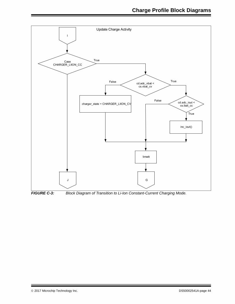
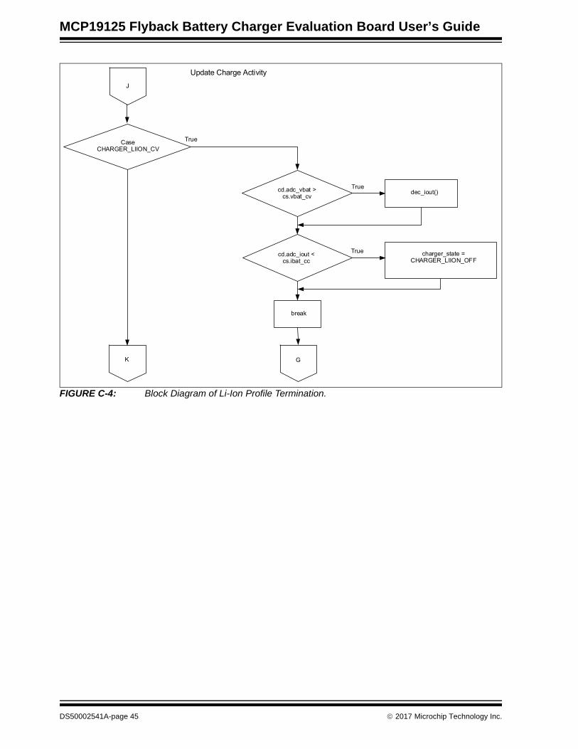
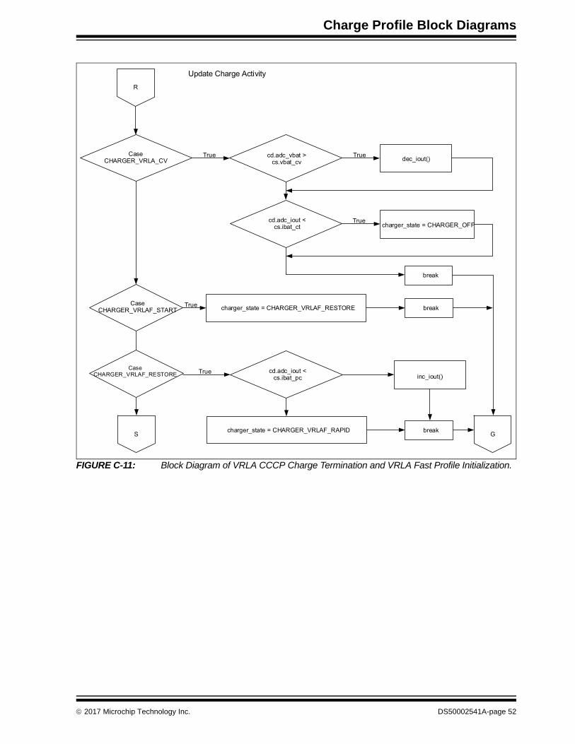
Figures C-1– C-16 show block diagrams for the various charge profiles. The block diagrams show the flow of logic that enables the MCP19125 to control the charge cycle for efficient battery charging.
FIGURE C-1: Block Diagram of Battery Charger OFF-to-ON Logic.
Update Charge Activity
adc_done = 0
Switch(cd.charger_state)
Case CHARGER_OFF Output Set to OffShutdown
Turn-On
Systems Parameter Initial
break
H G
True
True
2017 Microchip Technology Inc. DS50002541A-page 42

MCP19125 Flyback Battery Charger Evaluation Board User’s Guide
FIGURE C-2: Block Diagram of Li-Ion Profile Initialization.
Update Charge Activity
H
CaseCHARGER_LIION_START
CaseCHARGER_LIION_PRECONDITION
charger_state = CHARGER_LIION_PRECONDITION break
break
G
cd.adc_iout <cs.ibat_pc
cd.adc_vbat >cs.vbat_pc
charge_state = CHARGER_LIION_CC
inc_iout()
I
True
True
True
True
False
False
DS50002541A-page 43 2017 Microchip Technology Inc.
Charge Profile Block Diagrams
FIGURE C-3: Block Diagram of Transition to Li-Ion Constant-Current Charging Mode.
Update Charge Activity
I
CaseCHARGER_LIION_CC
charger_state = CHARGER_LIION_CV
break
G
cd.adc_vbat < cs.vbat_cv
inc_iout()
J
True
True
cd.adc_iout <cs.ibat_cc
True
False
False
2017 Microchip Technology Inc. DS50002541A-page 44
MCP19125 Flyback Battery Charger Evaluation Board User’s Guide
FIGURE C-4: Block Diagram of Li-Ion Profile Termination.
Update Charge Activity
J
CaseCHARGER_LIION_CV
charger_state = CHARGER_LIION_OFF
break
G
cd.adc_vbat > cs.vbat_cv
K
True
True
dec_iout()
cd.adc_iout < cs.ibat_cc
True
DS50002541A-page 45 2017 Microchip Technology Inc.

Charge Profile Block Diagrams
FIGURE C-5: Block Diagram of NiMH Profile Initialization and Transition to Rapid Charge Mode.
Update Charge Activity
K
CaseCHARGER_NIMH_START
CaseCHARGER_NIMH_RESTORE
charger_state = CHARGER_NIMH_RESTORE break
break
G
cd.adc_iout <cs.ibat_pc
cd.adc_vbat >cs.vbat_pc
charger_state = CHARGER_NIMH_RAPID
inc_iout()
L
True
True
True
True
False
False
cc.dtdt_countcd.eoc_status.dtdt = 1
charger_state = CHARGER_OFF
= 0
2017 Microchip Technology Inc. DS50002541A-page 46

MCP19125 Flyback Battery Charger Evaluation Board User’s Guide
FIGURE C-6: Block Diagram of NiMH Profile Transition to Trickle Charge Mode.
Update Charge Activity
L
CaseCHARGER_NIMH_RAPID
N
cs.ibat_cc – cd.adc_iout > 100
inc_iout() * 4
M
True
True
False
cs.ibat_cc – cd.adc_iout > 0
inc_iout()
False
Charge Timeout
charger_state = CHARGER_NIMH_TRICKLE
True
True
DS50002541A-page 47 2017 Microchip Technology Inc.

Charge Profile Block Diagrams
FIGURE C-7: Block Diagram of Voltage and Temperature Sense Termination Logic for NiMH Profile.
Update Charge Activity
N
dV/dt
dT/dt
Package Volt
break
G
True
True
Over
cd.eoc_status.dvdt = 1charger_state = CHARGER_NIMH_TRICKLE
cd.eoc_status.dtdt = 1charger_state = CHARGER_NIMH_TRICKLE
cd.eoc_status.dvdt = 1cd.eoc_status.dtdt = 1
charger_state = CHARGER_NIMH_TRICKLE
2017 Microchip Technology Inc. DS50002541A-page 48

MCP19125 Flyback Battery Charger Evaluation Board User’s Guide
FIGURE C-8: Block Diagram of NiMH Profile Charge Termination.
Update Charge Activity
M
CaseCHARGER_NIMH_TRICKLE
G
cs.ibat_ct = 0
P
True
True
False
cd.adc_iout –cs.ibat_ct
charger_state = CHARGER_OFF
break
dec_iout() dec_iout()
> 200< 200 & > 0
< 0
DS50002541A-page 49 2017 Microchip Technology Inc.

Charge Profile Block Diagrams
FIGURE C-9: Block Diagram of VRLA Profile Initialization and Transition to Rapid Charge Mode.
Update Charge Activity
P
CaseCHARGER_VRLA_START
CaseCHARGER_VRLA_PRECONDITION
charger_state = CHARGER_VRLA_PRECONDITION break
break
G
cd.adc_iout <cs.ibat_pc
cd.adc_vbat >cs.vbat_pc
charger_state = CHARGER_VRLA_RAPIDcd.dvdt_count init
cd.Pdvdt_count init
inc_iout()
Q
True
True
True
True
False
False
2017 Microchip Technology Inc. DS50002541A-page 50

MCP19125 Flyback Battery Charger Evaluation Board User’s Guide
FIGURE C-10: Block Diagram of Transition to Constant-Voltage Mode.
Update Charge Activity
Q
CaseCHARGER_VRLA_CC
G
cd.adc_vbat <cs.vbat_cv
R
True
True
False
cd.adc_iout <cs.ibat_cc
charger_state = CHARGER_VRLA_CV
break
- dV/dt
+ dV/dt
eof_dvdt
inc_iout()
TrueFalse
True
True
cd.eoc_status.dvdt = 1charger_state = CHARGER_OFF
True
cd.eoc_status.dvdt = 1Pdvdt init; VRLAdvdt = 1
charger_state = CHARGER_VRLA_CVparameter initial
DS50002541A-page 51 2017 Microchip Technology Inc.
Charge Profile Block Diagrams
FIGURE C-11: Block Diagram of VRLA CCCP Charge Termination and VRLA Fast Profile Initialization.
Update Charge Activity
R
CaseCHARGER_VRLA_CV
charger_state = CHARGER_OFF
break
cd.adc_iout <cs.ibat_ct
cd.adc_vbat >cs.vbat_cv
charger_state = CHARGER_VRLAF_RESTORE
Truedec_iout()
True
True
CaseCHARGER_VRLAF_START
Truebreak
CaseCHARGER_VRLAF_RESTORE
True cd.adc_iout <cs.ibat_pc inc_iout()
S Gbreakcharger_state = CHARGER_VRLAF_RAPID
2017 Microchip Technology Inc. DS50002541A-page 52

MCP19125 Flyback Battery Charger Evaluation Board User’s Guide
FIGURE C-12: Block Diagram of VRLA Fast Charge Profile Logic.
Update Charge Activity
S
GT
True
charger_state = CHARGER_VRLAF_TRICKLECount init
break
- dV/dt
+ dV/dt
eof_dvdt
inc_iout()
True
True
True
cd.eoc_status.dvdt = 1charger_state = CHARGER_OFF
True
cd.eoc_status.dvdt = 1Pdvdt init; VRLAdvdt = 1
True
timeoutcharger_state = CHARGER_VRLAF_TRICKLE
count and timer init
CaseCHARGER_VRLAF_RAPID
cd.adc_vbat <cs.vbat_cv
cd.adc_iout <cs.ibat_cc
True
charger_state = CHARGER_VRLAF_TRICKLEparameter initial
DS50002541A-page 53 2017 Microchip Technology Inc.

Charge Profile Block Diagrams
FIGURE C-13: Block Diagram of VRLA Fast Trickle Charge Mode and Profile Termination.
Update Charge ActivityT
G
True
charger_state = CHARGER_OFF
break
eof_dvdt
True
True
True
cd.eoc_status.dvdt = 1Pdvdt init; VRLAdvdt = 1
TrueCaseCHARGER_VRLAF_TRICKLE cs.ibat_ct = 0
charger_state = CHARGER_OFFparameter initial
cs.adc_iout –cs.ibat_ct
dec_iout() dec_iout_f()
> 200< 200 & > 0
< 0
+ dV/dt
Timeoutcharger_state = CHARGER_OFF
count and timer init
G
2017 Microchip Technology Inc. DS50002541A-page 54

MC
P1
91
25 F
lyb
ac
k B
atte
ry C
ha
rge
r Eva
lua
tion
Bo
ard
Us
er’s
Gu
ide
DS
50
00
25
41
A-p
ag
e 5
5
20
17
Micro
chip
Te
chn
olo
gy In
c.
break
break
CHARGER_LIFEPO4_CC
inc_iout ()
G
FIGURE C-14: Block Diagram of LiFEPO4 Profile Initialization.
TrueCase CHARGER_LIFEPO4_START
U
charger_state =
CHARGER_LIFEPO4_PRECONDITION
Update Charge Activity
TrueCaseCHARGER_LIFEPO4_PRECONDITION cd.adc_iout < cs.ibat_pc
True
True
cd.adc_vbat > cs.vbat_pc
V

Ch
arg
e P
rofile B
lock
Dia
gra
ms
2
01
7 M
icroch
ip T
ech
no
log
y Inc.
DS
50
00
25
41
A-p
ag
e 5
6 FIG
inc_iout()
Truecd.adc_iout < cs.ibat_cc
URE C-15: Block Diagram of Transition to LiFEPO4 Constant-Current Charging Mode.
Case
CHARGER_LIFEPO4_CC
V
Update Charge Activity
True cd.adc_vbat < cs.vbat_cv True
break
cd.charger_state =
CHARGER_LIFEPO4_CV
R G

MC
P1
91
25 F
lyb
ac
k B
atte
ry C
ha
rge
r Eva
lua
tion
Bo
ard
Us
er’s
Gu
ide
DS
50
00
25
41
A-p
ag
e 5
7
20
17
Micro
chip
Te
chn
olo
gy In
c.
cd.charger_state =
CHARGER_OFF
dec_iout ()
FIGURE C-16: Block Diagram of LiFEPO4 Profile Termination.
Case
CHARGER_LIFEPO4_CV
S
Update Charge Activity
Truecd.adc_vbat > cs.vbat_cv
True
break
T
cd.adc_iout < cs.ibat_ct
T
True

DS50002541A-page 58 2017 Microchip Technology Inc.
AMERICASCorporate Office2355 West Chandler Blvd.Chandler, AZ 85224-6199Tel: 480-792-7200 Fax: 480-792-7277Technical Support: http://www.microchip.com/supportWeb Address: www.microchip.com
AtlantaDuluth, GA Tel: 678-957-9614 Fax: 678-957-1455
Austin, TXTel: 512-257-3370
BostonWestborough, MA Tel: 774-760-0087 Fax: 774-760-0088
ChicagoItasca, IL Tel: 630-285-0071 Fax: 630-285-0075
DallasAddison, TX Tel: 972-818-7423 Fax: 972-818-2924
DetroitNovi, MI Tel: 248-848-4000
Houston, TX Tel: 281-894-5983
IndianapolisNoblesville, IN Tel: 317-773-8323Fax: 317-773-5453Tel: 317-536-2380
Los AngelesMission Viejo, CA Tel: 949-462-9523Fax: 949-462-9608Tel: 951-273-7800
Raleigh, NC Tel: 919-844-7510
New York, NY Tel: 631-435-6000
San Jose, CA Tel: 408-735-9110Tel: 408-436-4270
Canada - TorontoTel: 905-695-1980 Fax: 905-695-2078
ASIA/PACIFICAsia Pacific OfficeSuites 3707-14, 37th FloorTower 6, The GatewayHarbour City, Kowloon
Hong KongTel: 852-2943-5100Fax: 852-2401-3431
Australia - SydneyTel: 61-2-9868-6733Fax: 61-2-9868-6755
China - BeijingTel: 86-10-8569-7000 Fax: 86-10-8528-2104
China - ChengduTel: 86-28-8665-5511Fax: 86-28-8665-7889
China - ChongqingTel: 86-23-8980-9588Fax: 86-23-8980-9500
China - DongguanTel: 86-769-8702-9880
China - GuangzhouTel: 86-20-8755-8029
China - HangzhouTel: 86-571-8792-8115 Fax: 86-571-8792-8116
China - Hong Kong SARTel: 852-2943-5100 Fax: 852-2401-3431
China - NanjingTel: 86-25-8473-2460Fax: 86-25-8473-2470
China - QingdaoTel: 86-532-8502-7355Fax: 86-532-8502-7205
China - ShanghaiTel: 86-21-3326-8000 Fax: 86-21-3326-8021
China - ShenyangTel: 86-24-2334-2829Fax: 86-24-2334-2393
China - ShenzhenTel: 86-755-8864-2200 Fax: 86-755-8203-1760
China - WuhanTel: 86-27-5980-5300Fax: 86-27-5980-5118
China - XianTel: 86-29-8833-7252Fax: 86-29-8833-7256
ASIA/PACIFICChina - XiamenTel: 86-592-2388138 Fax: 86-592-2388130
China - ZhuhaiTel: 86-756-3210040 Fax: 86-756-3210049
India - BangaloreTel: 91-80-3090-4444 Fax: 91-80-3090-4123
India - New DelhiTel: 91-11-4160-8631Fax: 91-11-4160-8632
India - PuneTel: 91-20-3019-1500
Japan - OsakaTel: 81-6-6152-7160 Fax: 81-6-6152-9310
Japan - TokyoTel: 81-3-6880- 3770 Fax: 81-3-6880-3771
Korea - DaeguTel: 82-53-744-4301Fax: 82-53-744-4302
Korea - SeoulTel: 82-2-554-7200Fax: 82-2-558-5932 or 82-2-558-5934
Malaysia - Kuala LumpurTel: 60-3-6201-9857Fax: 60-3-6201-9859
Malaysia - PenangTel: 60-4-227-8870Fax: 60-4-227-4068
Philippines - ManilaTel: 63-2-634-9065Fax: 63-2-634-9069
SingaporeTel: 65-6334-8870Fax: 65-6334-8850
Taiwan - Hsin ChuTel: 886-3-5778-366Fax: 886-3-5770-955
Taiwan - KaohsiungTel: 886-7-213-7830
Taiwan - TaipeiTel: 886-2-2508-8600 Fax: 886-2-2508-0102
Thailand - BangkokTel: 66-2-694-1351Fax: 66-2-694-1350
EUROPEAustria - WelsTel: 43-7242-2244-39Fax: 43-7242-2244-393
Denmark - CopenhagenTel: 45-4450-2828 Fax: 45-4485-2829
Finland - EspooTel: 358-9-4520-820
France - ParisTel: 33-1-69-53-63-20 Fax: 33-1-69-30-90-79
France - Saint CloudTel: 33-1-30-60-70-00
Germany - GarchingTel: 49-8931-9700Germany - HaanTel: 49-2129-3766400
Germany - HeilbronnTel: 49-7131-67-3636
Germany - KarlsruheTel: 49-721-625370
Germany - MunichTel: 49-89-627-144-0 Fax: 49-89-627-144-44
Germany - RosenheimTel: 49-8031-354-560
Israel - Ra’anana Tel: 972-9-744-7705
Italy - Milan Tel: 39-0331-742611 Fax: 39-0331-466781
Italy - PadovaTel: 39-049-7625286
Netherlands - DrunenTel: 31-416-690399 Fax: 31-416-690340
Norway - TrondheimTel: 47-7289-7561
Poland - WarsawTel: 48-22-3325737
Romania - BucharestTel: 40-21-407-87-50
Spain - MadridTel: 34-91-708-08-90Fax: 34-91-708-08-91
Sweden - GothenbergTel: 46-31-704-60-40
Sweden - StockholmTel: 46-8-5090-4654
UK - WokinghamTel: 44-118-921-5800Fax: 44-118-921-5820
Worldwide Sales and Service
11/07/16