mcq - product presentation wmc rev. 00 · 2.3 oil-free compressor with magnetic bearings ......
TRANSCRIPT

INTERNAL USE ONLY
McQuay InternationalWMCNew Water Cooled Chiller with oil free centrifugal compressors Applied Systems - Strategic Marketing
INTERNAL USE ONLY2
Contents
2. Technical Features2.1 Features & benefits2.2 Range2.3 Oil-free compressor with magnetic bearings2.4 Electronic expansion valve2.5 P & I diagram – example: 1 compressor case2.6 Control Panel
1. Introducing WMC 1.1 Product Overview 2010 1.2 Range
3. Focus on the Range3.1 Product line-up3.2 Selection Software3.3 Operating Limits3.4 Dimensions & Weights3.5 Sound Levels3.6 Standard Options3.7 Options on request

INTERNAL USE ONLY3
Chapter 1---------------------------------
Introducing WMC
INTERNAL USE ONLY
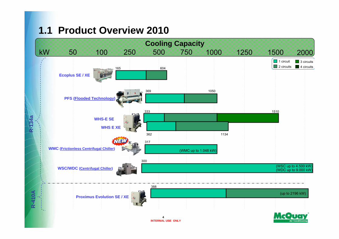
1.1 Product Overview 2010
50 100 250 500 750 1000 1250 1500Cooling Capacity
2000kW1 circuit2 circuits
3 circuits4 circuits
WSC/WDC (Centrifugal Chiller)
PFS (Flooded Technology)
Ecoplus SE / XE
(WDC up to 9.000 kW)
300
165 604
369 1050
333 1510
362 1134
R-1
34a WHS-E SE
WHS E XE
Proximus Evolution SE / XE(up to 2196 kW)
388
R-4
10A
(WSC up to 4.500 kW)
317
(WMC up to 1.048 kW)WMC (Frictionless Centrifugal Chiller)
4

INTERNAL USE ONLY
1.2 Range
Product Water cooled chiller with oil free centrifugal compressor
Refrigerant R-134a
Series name WMC
Cooling Capacity From 317 kW to 1.048 kW (nominal cooling capacity) - 6 sizes (Referred to: water evaporator 12/7°C --- water condenser 30/35°C)
Circuits 1 refrigerant circuit (1 or 2 compressors)
Efficiency versions XE High efficiency
Sound Versions ST Standard sound
5

INTERNAL USE ONLY6
Chapter 2---------------------------------
Technical Features
INTERNAL USE ONLY7
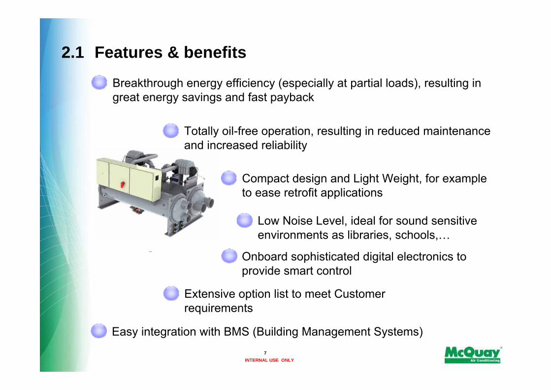
2.1 Features & benefits
Onboard sophisticated digital electronics to provide smart control
Extensive option list to meet Customer requirements
Breakthrough energy efficiency (especially at partial loads), resulting in great energy savings and fast payback
Totally oil-free operation, resulting in reduced maintenance and increased reliability
Compact design and Light Weight, for example to ease retrofit applications
Easy integration with BMS (Building Management Systems)
Low Noise Level, ideal for sound sensitive environments as libraries, schools,…
INTERNAL USE ONLY
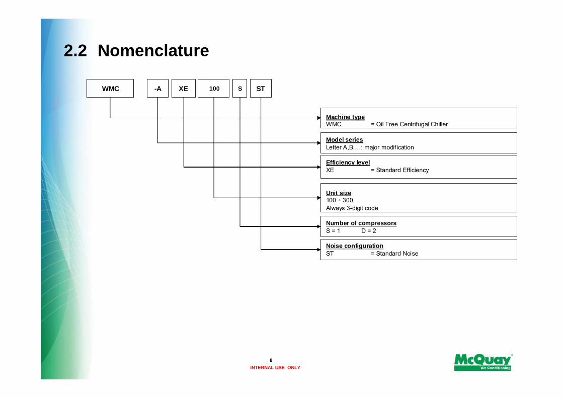
2.2 Nomenclature
8
Machine typeWMC = Oil Free Centrifugal Chiller
Model seriesLetter A,B,…: major modification
Efficiency levelXE = Standard Efficiency
Unit size100 ÷ 300Always 3-digit code
Number of compressorsS = 1 D = 2
Noise configurationST = Standard Noise
WMC -A XE 100 S ST

INTERNAL USE ONLY
2.3 Oil-free compressor with magnetic bearings
The compressor, specifically designed for HVACR industry, is a compact FULLY INTEGRATED SYSTEM including:
- Dual stage Centrifugal compressor
- Magnetic bearing system (instead of conventional bearings)
- Variable Speed Permanent Magnet Direct Drive Motor
9
INTERNAL USE ONLY
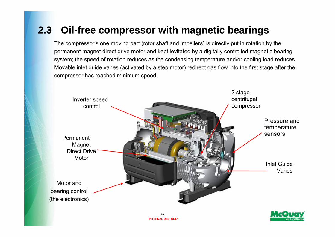
The compressor’s one moving part (rotor shaft and impellers) is directly put in rotation by the permanent magnet direct drive motor and kept levitated by a digitally controlled magnetic bearing system; the speed of rotation reduces as the condensing temperature and/or cooling load reduces. Movable inlet guide vanes (activated by a step motor) redirect gas flow into the first stage after the compressor has reached minimum speed.
2.3 Oil-free compressor with magnetic bearings
Pressure and temperature sensors
Inverter speed control
Permanent Magnet
Direct Drive Motor
Motor and bearing control(the electronics)
Inlet Guide Vanes
2 stage centrifugal compressor
10
INTERNAL USE ONLY
2.3 Oil-free compressor with magnetic bearings
11
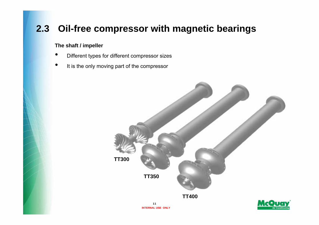
The shaft / impeller
• Different types for different compressor sizes
• It is the only moving part of the compressor
TT300
TT350
TT400
INTERNAL USE ONLY
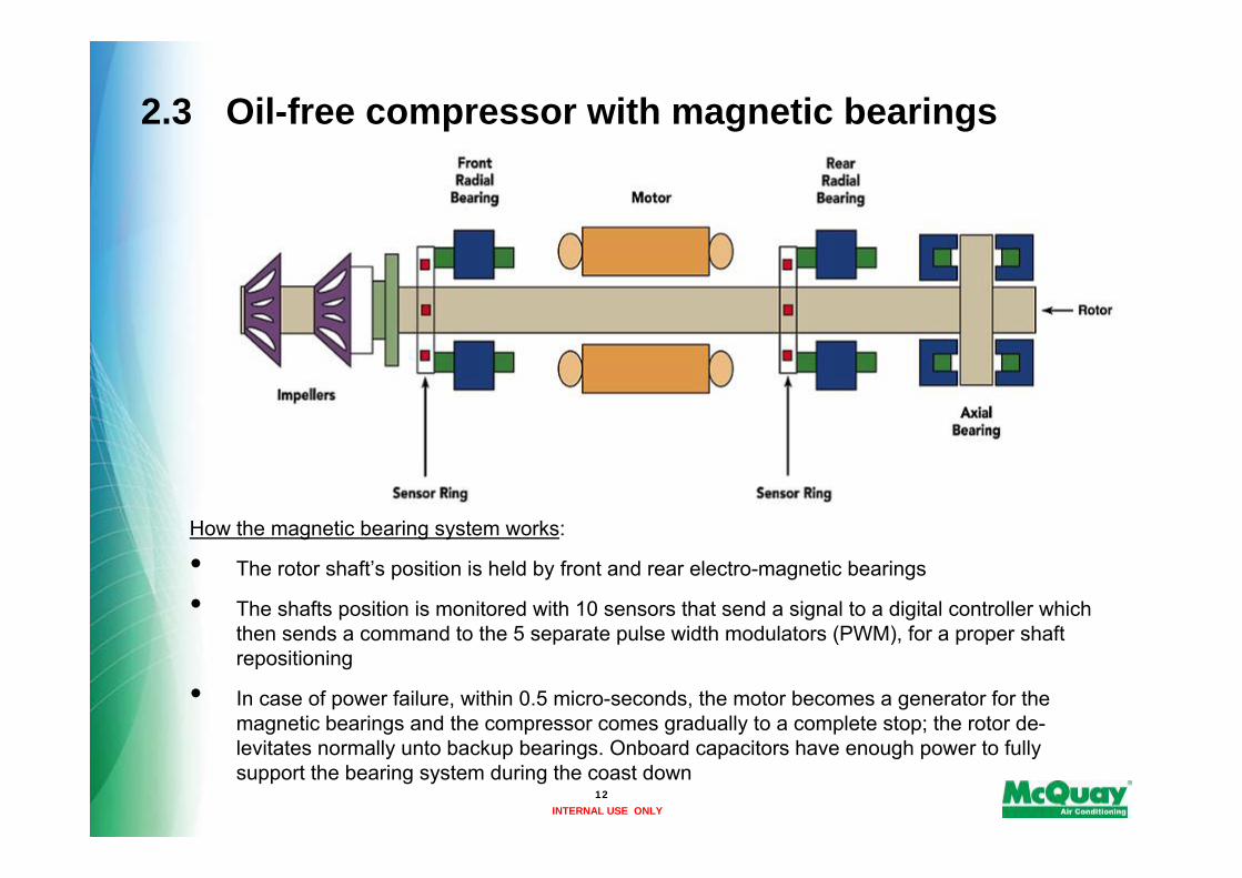
How the magnetic bearing system works:
• The rotor shaft’s position is held by front and rear electro-magnetic bearings
• The shafts position is monitored with 10 sensors that send a signal to a digital controller which then sends a command to the 5 separate pulse width modulators (PWM), for a proper shaft repositioning
• In case of power failure, within 0.5 micro-seconds, the motor becomes a generator for the magnetic bearings and the compressor comes gradually to a complete stop; the rotor de-levitates normally unto backup bearings. Onboard capacitors have enough power to fully support the bearing system during the coast down
12
2.3 Oil-free compressor with magnetic bearings

INTERNAL USE ONLY
Efficiency versionsavailable
Compressor cabinet
Variable Speed Permanent Magnet Direct Drive Motor
13
• Permanent magnet, placed onto the rotor, generate the magnetic flux that is necessary to provide torque; VFD (Variable Speed Drive) is required to allow a soft start (2 amps starting current) and the variability of speed (high speed, from 18,000 to 48,000 RPM).
• This motor, also known as ‘brushless’, is synchronous and is more efficient than the asynchronous because there are no losses into the rotor (as happens in the asynchronous motor to slip the frequency)
• The motor is refrigerant cooled and fully protected with thermistors.
2.3 Oil-free compressor with magnetic bearings

INTERNAL USE ONLY14
2.3 Oil-free compressor with magnetic bearings
Case 1 :
Asynchronous
Case 2 :
Synchronous with permanent
magnets
INTERNAL USE ONLY15
2.3 Oil-free compressor with magnetic bearings
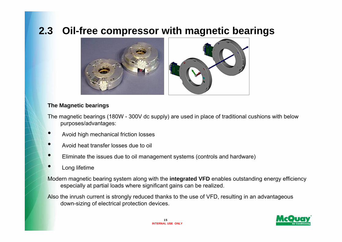
The Magnetic bearings
The magnetic bearings (180W - 300V dc supply) are used in place of traditional cushions with below purposes/advantages:
• Avoid high mechanical friction losses
• Avoid heat transfer losses due to oil
• Eliminate the issues due to oil management systems (controls and hardware)
• Long lifetime
Modern magnetic bearing system along with the integrated VFD enables outstanding energy efficiency especially at partial loads where significant gains can be realized.
Also the inrush current is strongly reduced thanks to the use of VFD, resulting in an advantageous down-sizing of electrical protection devices.

INTERNAL USE ONLY16
2.3 Oil-free compressor with magnetic bearings
The electronics
Inbuilt sophisticated electronics guarantee self-diagnostics on Motor, bearings, compressor, expansion valve, performance, events, faults,…and allow the exchange and visibility of data with the chiller controller

INTERNAL USE ONLY
2.3 Oil-free compressor with magnetic bearingsThe electronics
Line reactor Rectifier MotorDC-link capacitorsIGBT
Compressor controller
DC-DC converter PWM output
Magnetic bearings
Controller
ControlPower - GeneratorPower - Motor
Supply
3 Phases
380-480V
50-60HZ
17

INTERNAL USE ONLY
2.4 Electronic expansion valve
The unit is equipped with the most advanced electronic expansion valves to achieve precise control of refrigerant mass flow.
These valves, that typically work with a lower Δp between high and low pressure side than a thermostatic valve, allow the system to work
• within a wide operating range without any refrigerant flow problems
• with a perfect chilled water leaving temperature
Finally this type of valve allows the double set-point and generally the application as heat pump: this last point is not true for the WMC due to the envelope of the compressor (see also slide on ‘Operating limits’ )
18

INTERNAL USE ONLY19
2.5 P & I diagram – example: 1 compressor case
INTERNAL USE ONLY20
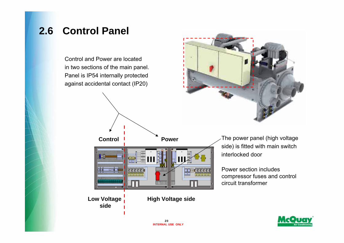
2.6 Control Panel
The power panel (high voltage side) is fitted with main switch interlocked door
Power section includes compressor fuses and control circuit transformer
Control and Power are locatedin two sections of the main panel.Panel is IP54 internally protected against accidental contact (IP20)
Control Power
High Voltage sideLow Voltageside

INTERNAL USE ONLY21
Chapter 3---------------------------------
Focus on the range
INTERNAL USE ONLY
3.1 Product line-up
22
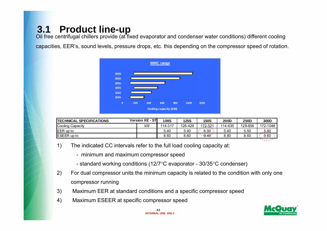
Oil free centrifugal chillers provide (at fixed evaporator and condenser water conditions) different cooling
capacities, EER’s, sound levels, pressure drops, etc. this depending on the compressor speed of rotation.
TECHNICAL SPECIFICATIONS 100S 125S 150S 200D 250D 300DkW 114-317 128-429 172-521 114-635 128-856 172-1048
5.40 5.40 6.00 5.40 5.50 5.908.60 8.60 9.40 8.80 8.60 9.60
Version XE - ST Cooling CapacityEER up toESEER up to
1) The indicated CC intervals refer to the full load cooling capacity at:
- minimum and maximum compressor speed
- standard working conditions (12/7°C evaporator - 30/35°C condenser)
2) For dual compressor units the minimum capacity is related to the condition with only one
compressor running
3) Maximum EER at standard conditions and a specific compressor speed
4) Maximum ESEER at specific compressor speed
0 200 400 600 800 1000 1200
Cooling capacity (kW)
100S125S
150S200D
250D
300D
WMC range

INTERNAL USE ONLY
3.2 Selection Software• The WMC selection software is basically a excel-based tool, very easy and intuitive.
• To access the software the user is required to enter ‘username’ and ‘password’ (provided by Strategic Marketing)
• Calculations of IPLV, ESEER and NPLV are allowed, providing for each point all the most important technical parameters as water flow, pressure drops, capacity, power input, etc
• Once generated, selections can be easily saved, archived and/or sent by e-mail.
• A dedicated selection software short guide is available to show how to use the tool.
23
INTERNAL USE ONLY
3.3 Operating Limits
0
5
10
15
20
25
30
35
40
45
50
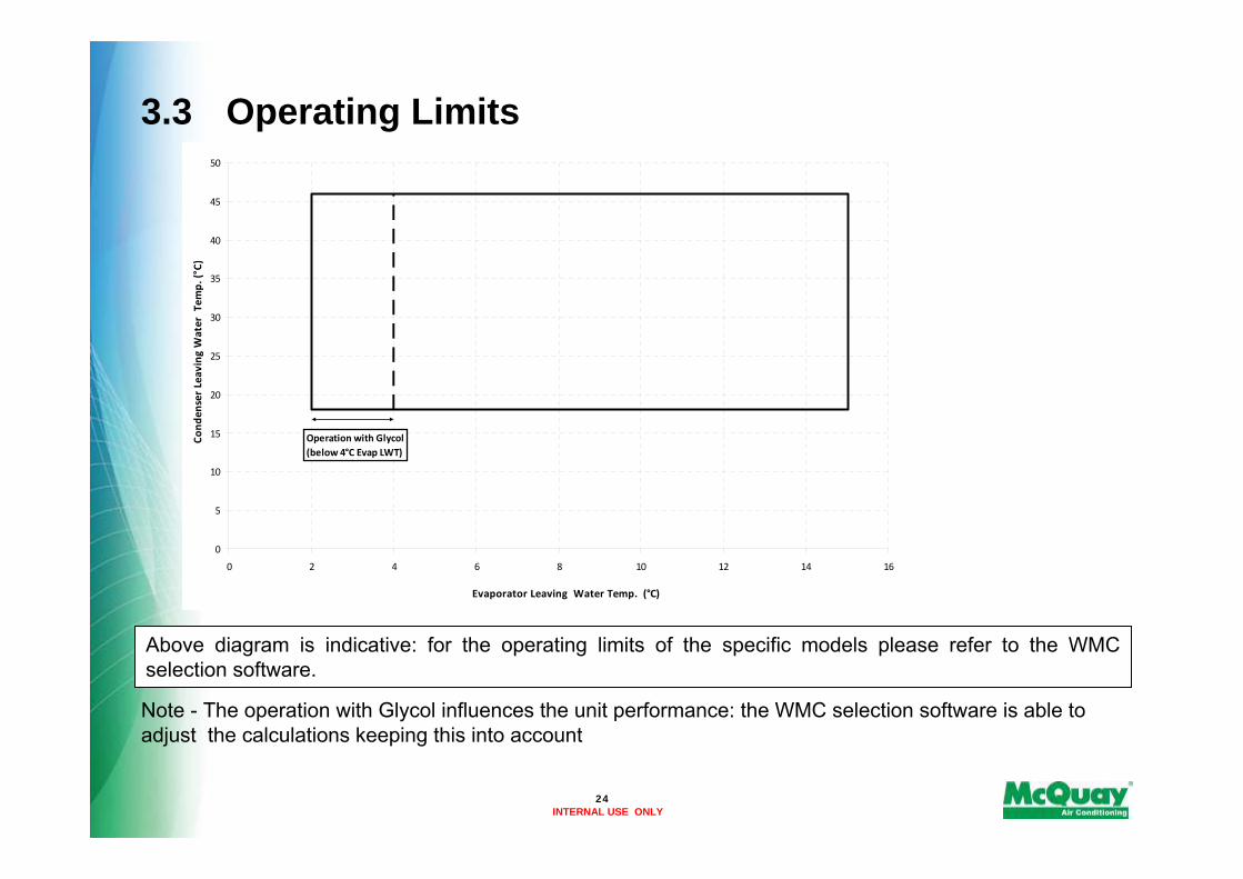
0 2 4 6 8 10 12 14 16
Evaporator Leaving Water Temp. (°C)
Cond
enser Leaving Water Tem
p. (°C)
Operation with Glycol(below 4°C Evap LWT)
Above diagram is indicative: for the operating limits of the specific models please refer to the WMC selection software.
Note - The operation with Glycol influences the unit performance: the WMC selection software is able to adjust the calculations keeping this into account
24

INTERNAL USE ONLY
3.3 Operating Limits
Max saturated discharge temperature: 56°C
Max saturated discharge temperature: 45°C
25

INTERNAL USE ONLY
3.4 Dimensions & Weights
179417481755182318231823mm(C) Height
190418531790127612761276mm(B) Width
340132893441341932543254mm(A) Length
533045484074281226342520kgOperating weight
476540953709254624162360kgShipping weight
300D250D200D150S125S100SWeight & dimensions
26

INTERNAL USE ONLY
Reduction to be applied to standard sound levels
The WMC chillers are very quiet, this mainly thanks to the use of oil-free Centrifugal compressor with magnetic bearings; additional reduction of sound level is possible through the sound proof cabinet (on request)
Figures in the table are related to standard working conditions (evaporator water 12/7°C and condenser water 30/35°C) and maximum cooling capacity
Sound pressure level correction for different distances
3.5 Sound Levels
Power63 Hz 125 Hz 250 Hz 500 Hz 1000 Hz 2000 Hz 4000 Hz 8000 Hz dB(A) dB(A)
100S 38.7 50.1 55.6 58.8 64.5 62.7 63.6 66.6 70.9 89.0125S 39.2 50.6 57.0 59.8 66.0 63.5 64.7 67.9 72.0 90.1150S 39.7 51.7 57.7 61.1 66.8 64.6 66.1 68.5 73.0 91.2200D 41.7 53.0 58.6 61.8 67.4 65.8 66.4 69.6 73.8 92.4250D 42.2 53.6 60.0 62.9 69.1 66.4 67.9 71.0 75.1 93.6300D 42.7 54.9 60.7 63.9 69.8 67.5 69.1 71.3 75.9 94.6
Sound pressure level at 1 m from the unit in semispheric free field (rif. 2 x 10⁻⁵ Pa)Unit size
1m 5m 10m 15m 20m 25m 50m100S 0.0 -8.7 -13.7 -16.9 -19.2 -21.1 -26.9125S 0.0 -8.7 -13.8 -17.0 -19.3 -21.1 -26.9150S 0.0 -8.7 -13.7 -16.9 -19.2 -21.0 -26.8200D 0.0 -8.4 -13.4 -16.6 -18.9 -20.7 -26.5250D 0.0 -8.5 -13.5 -16.6 -18.9 -20.7 -26.5300D 0.0 -8.4 -13.4 -16.5 -18.8 -20.6 -26.4
Unit sizeDistance
27

INTERNAL USE ONLY
Following accessories are supplied as Standard on basic unit:
• Evaporator – 2 passes configuration• Evaporator Victaulic kit – Hydraulic joint with gasket for an easy and quick water connection• Evaporator water side design pressure 10 bar• 20mm evaporator insulation• Condenser – 2 passes configuration• Condenser Victaulic kit – Hydraulic joint with gasket for an easy and quick water connection• Condenser water side design pressure 10 bar• Electronic expansion valve• High pressure side manometers on evaporator and condneser• Water pressure differential switch on evaporator and condenser – Factory mounted, differential switchis available to detect evaporator and condenser loss of flow• Inverter compressor starter – For low inrush current and reduced starting torque• Double pressure relief valve with diverter• Current limit – To limit maximum absorbed current of the unit whenever is required• Hour run meter• General fault contactorSet-point reset – The leaving water temperature set-point can be overwritten withthe following options: 4-20mA from external source (by user); outside ambient temperature; evaporator watetemperature Δt• Demand limit – User can limit the load of the unit by 4-20mA signal or by network system• Alarm from external device – Microprocessor is able to receive an alarm signal from an external device (pump etc…). User can decide if this alarm signal will stop or not the unit
3.6 Standard Options
28

INTERNAL USE ONLY
Following options are available on request:
• Evaporator and condenser 1/3 passes – availability of these configurations must be checked on the selection software• Evaporator and condenser flange kit – in place of the standard victaulic connections• Evaporator and condenser double flange kit• Evaporator and condenser marine water box (with victaulic or flanged connections). To save time and work marine water boxes cover can be easily removed to clean internal tubes without the disconnection of water pipes.• Evaporator and condenser water side design pressure 21 bar• 20mm condenser insulation• Cu-Ni 90-10 condenser tubes - To work with sea water the heat exchangers are fitted with Cu-Ni tubes and special protection inside the end covers• Evaporator/Condenser Flow switch – Supplied separately to be wired and installed on the evaporator water piping (by the customer)• Suction line shut off valve – Installed on the suction port of the compressor to facilitate maintenance operation• Energy Meter – installed inside the control box, this accessory shows on a digital display: Line-to-Line Voltage, Phase and Average Current, Active and Reactive Power, Active Energy, Frequency• Rubber type antivibration mounts – Supplied separately, these are positioned under the base of theunit during installation. Ideal to reduce the vibrations when the unit is floor mounted• Sound proof system - "integral kind“cabinet to reach the best performance in noise reduction• Witness test – at customer’s presence, in accordance with the procedures indicated on the test form
3.7 Options on request
29

INTERNAL USE ONLY
Thank You
30