mdg120phvw installation instruction
DESCRIPTION
manual de instalacion maytag MDG120PHVWTRANSCRIPT

MDG120PVV(Phase 7/Non-Coin with S.A.F.E.)
Installation Manual
WARNING: For your safety the information inthis manual must be followed to minimize therisk of fire or explosion or to prevent propertydamage, personal injury or death.
— Do not store or use gasoline or other flammablevapors and liquids in the vicinity of this or anyother appliance.
— WHAT TO DO IF YOU SMELL GAS:
• Do not try to light any appliance.• Do not touch any electrical switch; do not
use any phone in your building.• Clear the room, building or area of all
occupants.• Immediately call your gas supplier from a
neighbor’s phone. Follow the gas supplier’sinstructions.
• If you cannot reach your gas supplier, callthe fire department.
— Installation and service must be performed by aqualified installer, service agency or the gassupplier.
AVERTISSEMENT: Assurez-vous de biensuivre les instructions données dans cette noticepour réduire au minimum le risque d’incendieou d’explosion ou pour éviter tout dommagematériel, toute blessure ou la mort.
— Ne pas entreposer ni utiliser d’essence nid’autres vapeurs ou liquides inflammables àproximité de cet appareil ou de tout autreappareil.
— QUE FAIRE SI VOUS SENTEZ UNE ODEURDE GAZ:
• Ne pas tenter d’allumer d’appareils.• Ne touchez à aucun interrupteur. Ne pas
vous servir des téléphones se trouvant dansle bâtiment.
• Évacuez la pièce, le bâtiment ou la zone.• Appelez immédiatement votre fournisseur
de gaz depuis un voisin. Suivez lesinstructions du fournisseur.
• Si vous ne pouvez rejoindre le fournisseurde gaz, appelez le service des incendies.
— L’installation et l’entretien doivent être assurés parun installateur ou un service d’entretien qualifiéou par le fournisseur de gaz.
122302JEV/mcronan Part No. 113395
RETAIN THESE INSTRUCTIONS IN A SAFEPLACE FOR FUTURE REFERENCE
Downloaded from www.Manualslib.com manuals search engine

Retain This Manual In A Safe Place For Future ReferenceThis product embodies advanced concepts in engineering, design, and safety. If this product is properly maintained, it willprovide many years of safe, efficient, and trouble free operation.
ONLY qualified technicians should service this equipment.
OBSERVE ALL SAFETY PRECAUTIONS displayed on the equipment or specified in the installation manual included withthe dryer.
The following “FOR YOUR SAFETY” caution must be posted near the dryer in a prominent location.
“IMPORTANT NOTE TO PURCHASER”
Information must be obtained from your local gas supplier on the instructionsto be followed if the user smells gas. These instructions must be posted in aprominent location near the dryer.
We have tried to make this manual as complete as possible and hope you will find it useful. The manufacturer reserves theright to make changes from time to time, without notice or obligation, in prices, specifications, colors, and material, and tochange or discontinue models. The illustrations included in this manual may not depict your particular dryer exactly.
ImportantFor your convenience, log the following information:
DATE OF PURCHASE ________________________________ MODEL NO. __________________________________________
DEALER’S NAME __________________________________________________________________________________________
Serial Number(s) ________________________________________________________________________________________
________________________________________________________________________________________
________________________________________________________________________________________
For replacement parts, contact the dealer from which the dryer was purchased or contact:
Maytag Co.403 West Fourth Street North
Newton, Iowa 50208(641) 787-7000
FOR YOUR SAFETY
Do not store or use gasoline orother flammable vapors andliquids in the vicinity of this orany other appliance.
POUR VOTRE SÉCURITÉ
Ne pas entreposer ni utiliser d’essenceni d’autres vapeurs ou liquidesinflammables à proximité de cetappareil ou de tout autre appareil.
MDG120
Downloaded from www.Manualslib.com manuals search engine

IMPORTANT
YOU MUST DISCONNECT AND LOCKOUT THE ELECTRIC SUPPLY AND THE GASSUPPLY BEFORE ANY COVERS OR GUARDS ARE REMOVED FROM THEMACHINE TO ALLOW ACCESS FOR CLEANING, ADJUSTING, INSTALLATION, ORTESTING OF ANY EQUIPMENT PER OSHA (Occupational Safety and HealthAdministration) STANDARDS.
WARNING
CHILDREN SHOULD NOT BE ALLOWED TO PLAY ON OR NEAR THE DRYER(S).
CHILDREN SHOULD BE SUPERVISED IF NEAR DRYERS IN OPERATION.
CAUTION
DRYERS SHOULD NEVER BE LEFT UNATTENDED WHILE IN OPERATION.
FOR YOUR SAFETY
DO NOT DRY MOP HEADS IN THE DRYER.
DO NOT USE DRYER IN THE PRESENCE OF DRY CLEANING FUMES.
WARNING
UNDER NO CIRCUMSTANCES should the dryer door switch, lint drawer switch, orthe heat safety circuits ever be disabled.
“Caution: Label all wires prior todisconnection when servicing controls. Wiringerrors can cause improper operation.”
«Attention: Au moment de l’entretien descommandes, étiquetez tous les fils avant deles débrancher. Des erreurs de câblagepeuvent entraîner un fonctionnementinadéquat et dangereux.»
Downloaded from www.Manualslib.com manuals search engine

WARNING
The dryer must never be operated with any of the back guards, outer tops, or servicepanels removed. PERSONAL INJURY OR FIRE COULD RESULT.
IMPORTANT
PLEASE OBSERVE ALL SAFETY PRECAUTIONS displayed on the equipment and/orspecified in the installation manual included with the dryer.
WARNING
DRYER MUST NEVER BE OPERATED WITHOUT THE LINT FILTER/SCREEN INPLACE, EVEN IF AN EXTERNAL LINT COLLECTION SYSTEM IS USED.
Dryer must not be installed or stored in an area where it will be exposed to water or weather.
The wiring diagram for the dryer is located in the front electrical control box area.
IMPORTANT
Dryer must be installed in a location/environment, which the ambient temperatureremains between 40° F (4.44° C) and 130° F (54.44° C).
Downloaded from www.Manualslib.com manuals search engine

SECTION IIMPORTANT INFORMATION ............................................................................... 3
A. Receiving and Handling ............................................................................................................... 3B. Safety Precautions ...................................................................................................................... 4
SECTION IISPECIFICATIONS/COMPONENT IDENTIFICATION..................................... 6
A. Specifications ............................................................................................................................. 6B. Component Identification ............................................................................................................ 8
SECTION IIIINSTALLATION PROCEDURES ......................................................................... 10
A. Location Requirements ............................................................................................................. 10B. Unpacking/Setting Up ............................................................................................................... 11C. Dryer Enclosure Requirements .................................................................................................. 14D. Fresh Air Supply Requirements ................................................................................................. 15E. Exhaust Requirements ............................................................................................................... 16F. Electrical Information ................................................................................................................ 22G. Gas Information ........................................................................................................................ 26H. Preparation For Operation ........................................................................................................ 30I. Preoperational Tests ................................................................................................................. 31J. Shutdown Instructions ............................................................................................................... 33K. Operating Instructions ............................................................................................................... 34
SECTION IVSERVICE/PARTS INFORMATION ...................................................................... 35
A. Service ..................................................................................................................................... 35B. Parts ........................................................................................................................................ 35
SECTION VWARRANTY INFORMATION............................................................................... 36
A. Returning Warranty Cards ......................................................................................................... 36B. Warranty .................................................................................................................................. 36
SECTION VIROUTINE MAINTENANCE .................................................................................. 37
A. Cleaning ................................................................................................................................... 37B. Adjustments ............................................................................................................................. 39C. Lubrication ............................................................................................................................... 39
Table of Contents
Downloaded from www.Manualslib.com manuals search engine

SECTION VIIDATA LABEL INFORMATION ............................................................................. 40
A. Data Label ............................................................................................................................... 40
SECTION VIIIREVERSING TIMER SPIN/DWELL ADJUSTMENTS..................................... 42
SECTION IXPROCEDURE FOR FUNCTIONAL CHECK OF REPLACEMENTCOMPONENTS........................................................................................................ 43
SECTION XSENSOR ACTIVATED FIRE EXTINGUISHING (S.A.F.E.) SYSTEM ........... 45
Installation ...................................................................................................................................... 46Sensor Activated Fire Extinguishing (S.A.F.E.) System Theory of Operation .................................... 49System Reset .................................................................................................................................. 49Non-Coin S.A.F.E. System Check Procedure ................................................................................. 49Sensor Activated Fire Extinguishing (S.A.F.E.) System Parts Break Down ....................................... 50
Downloaded from www.Manualslib.com manuals search engine

3
SECTION IIMPORTANT INFORMATION
A. RECEIVING AND HANDLING
The dryer is shipped in a protective stretch wrap cover with protective cardboard corners and top cover(or optional box) as a means of preventing damage in transit. Upon delivery, the dryer and/or packaging, andwooden skid should be visually inspected for shipping damage. If any damage whatsoever is noticed, inspectfurther before delivering carrier leaves.
Dryers damaged in shipment:
1. ALL dryers should be inspected upon receipt and before they are signed for.
2. If there is suspected damage or actual damage, the trucker’s receipt should be so noted.
3. If the dryer is damaged beyond repair, it should be refused. Those dryers, which were not damaged in adamaged shipment, should be accepted, but the number received and the number refused must be notedon the receipt.
4. If you determine that the dryer was damaged after the trucker has left your location, you should call thedelivering carrier’s freight terminal immediately and file a claim. The freight company considers thisconcealed damage. This type of freight claim is very difficult to get paid and becomes extremely difficultwhen more than a day or two passes after the freight was delivered. It is your responsibility to file freightclaims. Dryer/parts damaged in transit cannot be claimed under warranty.
5. Freight claims are the responsibility of the consignee, and ALL claims must be filed at the receiving end.Manufacturer assumes no responsibility for freight claims or damages.
IMPORTANT: The dryer must be transported and handled in an upright position at ALL times.
Downloaded from www.Manualslib.com manuals search engine

4
B. SAFETY PRECAUTIONS
WARNING: For your safety, the information in this manual must be followed to minimize the risk offire or explosion or to prevent property damage, personal injury, or loss of life.
WARNING: The dryer must never be operated with any of the back guards, outer tops,or service panels removed. PERSONAL INJURY OR FIRE COULD RESULT.
1. DO NOT store or use gasoline or other flammable vapors and liquids in the vicinity of this or any otherappliance.
2. Purchaser/user should consult the local gas supplier for proper instructions to be followed in the eventthe user smells gas. The instructions should be posted in a prominent location.
3. WHAT TO DO IF YOU SMELL GAS...
a. DO NOT try to light any appliance.
b. DO NOT touch any electrical switch.
c. DO NOT use any phone in your building.
d. Clear the room, building, or area of ALL occupants.
e. Immediately call your gas supplier from a neighbor’s phone. Follow the gas supplier’s instructions.
f. If you cannot reach your gas supplier, call the fire department.
4. Installation and service must be performed by a qualified installer, service agency, or gas supplier.
5. Dryer(s) must be exhausted to the outdoors.
6. Although Maytag produces a very versatile dryer, there are some articles that, due to fabric compositionor cleaning method, should not be dried in it.
WARNING: Dry only water washed fabrics. DO NOT dry articles spotted or washed in drycleaning solvents, a combustible detergent, or “all purpose” cleaner.EXPLOSION COULD RESULT.
WARNING: DO NOT dry rags or articles coated or contaminated with gasoline, kerosene, oil, paint,or wax.EXPLOSION COULD RESULT.
WARNING: DO NOT dry mop heads. Contamination by wax or flammable solvents will create afire hazard.
Downloaded from www.Manualslib.com manuals search engine

5
WARNING: DO NOT use heat for drying articles that contain plastic, foam, sponge rubber, orsimilarly textured rubber materials. Drying in a heated basket (tumbler) may damageplastics or rubber and may be a fire hazard.
7. A program should be established for the inspection and cleaning of lint in the heating unit area, exhaustductwork, and inside the dryer. The frequency of inspection and cleaning can best be determined fromexperience at each location.
WARNING: The collection of lint in the burner area and exhaust ductwork can create a potentialfire hazard.
8. For personal safety, the dryer must be electrically grounded in accordance with local codes and/or theNational Electrical Code ANSI/NFPA NO. 70-LATEST EDITION, or in Canada, the CanadianElectrical Codes Parts 1 & 2 CSA C22.1-1990 or LATEST EDITION.
NOTE: Failure to do so will VOID THE WARRANTY.
9. UNDER NO CIRCUMSTANCES should the dryer door switch, lint drawer switch, or the heat safetycircuits ever be disabled.
WARNING: PERSONAL INJURY OR FIRE COULD RESULT.
10. This dryer is not to be used in the presence of dry cleaning solvents or fumes.
11. Remove articles from the dryer as soon as the drying cycle has been completed.
WARNING: Articles left in the dryer after the drying and cooling cycles have been completed cancreate a fire hazard.
12. READ AND FOLLOW ALL CAUTION AND DIRECTION LABELS ATTACHED TO THEDRYER.
13. For safety, proper operation, and optimum performance, the dryer must not be operated with a load lessthan sixty-six percent (66%), 85 lbs (38 kg) of its rated capacity.
WARNING: YOU MUST DISCONNECT AND LOCKOUT THE ELECTRIC SUPPLYAND THE GAS SUPPLY BEFORE ANY COVERS OR GUARDS AREREMOVED FROM THE MACHINE TO ALLOW ACCESS FOR CLEANING,ADJUSTING, INSTALLATION, OR TESTING OF ANY EQUIPMENT PEROSHA (Occupational Safety and Health Administration) STANDARDS.
IMPORTANT: Dryer must be installed in a location/environment, which the ambienttemperature remains between 40° F (4.44° C) and 130° F (54.44° C).
Downloaded from www.Manualslib.com manuals search engine

6
SECTION IISPECIFICATIONS/COMPONENT IDENTIFICATION
A. SPECIFICATIONS
NOTE: Manufacturer reserves the right to make changes in specifications at any time without notice orobligation.
GAS
Shaded areas are stated in metric equivalents 9/4/03
MAXIMUM CAPACITY (DRY WEIGHT) 120 lbs 54.4 kg
BASKET (TUMBLER) DIAMETER 44-1/2” 113 cm
BASKET (TUMBLER) DEPTH 42-1/2” 107.9 cm
BASKET (TUMBLER) MOTOR 3/4 hp 0.560 kW
BLOWER MOTOR 3 hp 2.238 kW
DOOR OPENING (DIAMETER) 31-3/8” 79.7 cm
BASKET (TUMBLER) VOLUME 38.2 cu ft 1.08 cu m
AIRFLOW 2,150 cfm 60.88 cmm
S.A.F.E. WATER CONNECTION 3/4-11.5 NH
VOLTAGE AVAILABLE 208-575v 3ø 3, 4w 50/60 Hz
APPROX. WEIGHT (UNCRATED) 1,349 lbs 611.9 kg
APPROX. WEIGHT (CRATED) 1,489 lbs 675.4 kg
HEAT INPUT 375,000 Btu/hr 94,500 kcal/hr
INLET SIZE 1-1/4” F.N.P.T.
Downloaded from www.Manualslib.com manuals search engine

7
NOTE: Manufacturer reserves the right to make changes in specifications at any time without notice orobligation.
Specifications – Gas
Downloaded from www.Manualslib.com manuals search engine

8
B. COMPONENT IDENTIFICATION
1. Dryer Front View
Illus. No. Description
1 Microprocessor Control/Keyboard (touch pad) Panel Assembly (controls)2 Control (top access) Door Assembly3 Main Door Assembly4 Lint Door Assembly5 Lint Drawer6 Wire Diagram (located behind control door)7 Top Console (module) Assembly
Downloaded from www.Manualslib.com manuals search engine
9
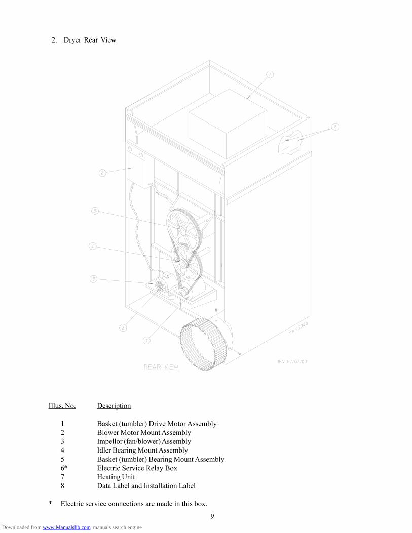
2. Dryer Rear View
Illus. No. Description
1 Basket (tumbler) Drive Motor Assembly2 Blower Motor Mount Assembly3 Impellor (fan/blower) Assembly4 Idler Bearing Mount Assembly5 Basket (tumbler) Bearing Mount Assembly6* Electric Service Relay Box7 Heating Unit8 Data Label and Installation Label
* Electric service connections are made in this box.
Downloaded from www.Manualslib.com manuals search engine

10
SECTION IIIINSTALLATION PROCEDURES
Installation should be performed by competent technicians in accordance with local and state codes. In theabsence of these codes, the installation must conform to applicable American National Standards: ANSI Z223.1-LATEST EDITION (National Fuel Gas Code) or ANSI/NFPA NO. 70-LATEST EDITION (National ElectricalCode) or in Canada, the installation must conform to applicable Canadian Standards: CAN/CGA-B149.1-M91(Natural Gas) or CAN/CGA-B149.2-M91 (Liquid Propane [L.P.] Gas) or LATEST EDITION (for GeneralInstallation and Gas Plumbing) or Canadian Electrical Codes Parts 1 & 2 CSA C22.1-1990 or LATESTEDITION (for Electrical Connections).
A. LOCATION REQUIREMENTS
Before installing the dryer, be sure the location conforms to local codes and ordinances. In the absence of suchcodes or ordinances the location must conform with the National Fuel Gas Code ANSI.Z223.1 LATESTEDITION, or in Canada, the installation must conform to applicable Canadian Standards: CAN/CGA-B149.1-M91 (Natural Gas) or CAN/CGA-B149.2-M91 (L.P. Gas) or LATEST EDITION (for General Installation andGas Plumbing).
1. The dryer must be installed on a sound level floor capable of supporting its weight. Carpeting must beremoved from the floor area that the dryer is to rest on.
IMPORTANT: “The dryer must be installed on noncombustible floors only.”
2. The dryer must not be installed or stored in an area where it will be exposed to water and/or weather.
3. The dryer is for use in noncombustible locations.
4. Provisions for adequate air supply must be provided as noted in this manual (refer to Fresh Air SupplyRequirements in Section D).
5. Clearance provisions must be made from combustible construction as noted in this manual (refer toDryer Enclosure Requirements in Section C).
6. Provisions must be made for adequate clearances for servicing and for operation as noted in this manual(refer to Dryer Enclosure Requirements in Section C).
7. Dryer must be exhausted to the outdoors as noted in this manual (refer to Exhaust RequirementsSection E).
8. Dryer must be located in an area where correct exhaust venting can be achieved as noted in this manual(refer to Exhaust Requirements in Section E).
IMPORTANT: Dryer should be located where a minimum amount of exhaust duct will be necessary.
9. The dryer must be installed with a proper exhaust duct connection to the outside.
Downloaded from www.Manualslib.com manuals search engine

11
10. The dryer must be installed with provisions for adequate combustion and make-up air supply.
CAUTION: This dryer produces combustible lint and must be exhausted to the outdoors. Every 6months, inspect the exhaust ducting and remove any lint build up.
IMPORTANT: Dryer must be installed in a location/environment, which the ambienttemperature remains between 40° F (4.44° C) and 130° F (54.44° C).
B. UNPACKING/SETTING UP
Remove protective shipping material (i.e., plastic wrap, and/or optional shipping box) from dryer.
IMPORTANT: Dryer must be transported and handled in an upright position at ALL times.
The dryer can be moved to its final location while still attached to the skid or with the skid removed. To unskidthe dryer, locate and remove the four (4) lag bolts securing the base of the dryer to the wooden skid. Two (2) arelocated at the rear base (remove the back panel for access) and two (2) are located in the bottom of the lintchamber. To remove the two (2) lag bolts located in the lint chamber area, remove the lint drawer and the three(3) Phillips head screws securing lint door in place.
1. Leveling Dryer
a. To level dryer, place 4-inch (10.16 cm) square metal shims (refer to illustration above) or othersuitable material under the base pads. It is suggested that the dryer be tilted slightly to the rear.
Downloaded from www.Manualslib.com manuals search engine

12
2. If more headroom is needed when moving dryer into position, the top console (module) may be removed.
a. To Remove Top Console (Module)
1) Disconnect the ground wire (A) at the rear upper left hand corner of dryer.
2) Remove the eight (8) sets of nuts and washers (B) holding the console (module) to base.3) Open the control door/control panel and disconnect the white 15-pin plug connector (C) (illustration
below) located in the base of the control box.
4) Disconnect white plug connector located outside back side of the control box (provides power toheat circuit).
5) Lift the console (module) off the dryer base.
IMPORTANT: The dryer must be transported and handled in an upright position at ALL times.
Downloaded from www.Manualslib.com manuals search engine

13
3. Exhaust Transition Piece
a. Inside the basket (tumbler) of this dryer is anexhaust transition piece that must be installed onthe outlet of the exhaust before any further ventingis connected:
1) Remove the exhaust transition piece from thebasket (tumbler) and place it on the exhaustoutlet.
2) Using the screws provided, secure the exhausttransition piece to the dryer.
NOTE: It is recommended that this joint be tapedas well as ALL other duct joints to preventmoisture and lint from escaping into thebuilding.
WARNINGAn exhaust duct transition piece is shipped inside of the dryer’stumbler and must be installed on the dryer ’sexhaust duct, with the hardware provided, BEFORElocation venting is connected to the dryer.
THIS EXHAUST DUCT TRANSITION PIECEMUST BE INSTALLED FIRST!
Failure to observe this installation requirement may result indamage to the dryer, create a FIRE HAZARD and will VOIDthe manufacturer’s warranty.
012999JEV-GS/cj P/N: 114092
Downloaded from www.Manualslib.com manuals search engine

14
C. DRYER ENCLOSURE REQUIREMENTS
Even though a 12-inch (30.48 cm) clearance is acceptable, it is recommended that the rear of the dryer bepositioned approximately 2 feet (0.60 meters) from the nearest obstruction (i.e., wall) for ease of installation,maintenance, and service. Bulkheads and partitions should be made from noncombustible materials. Theclearance between the bulkhead header and the dryer must be a minimum of 4-inches (10.16 cm) and must notextend more than 4-inches (10.16 cm) to the rear of the dryer front. The bulkhead facing must not be closedin ALL the way to the top of the dryer. A 2-inch (5.08 cm) clearance is required.
NOTE: Bulkhead facing should not be installed until after dryer is in place. Ceiling area must belocated a minimum of 12-inches (30.48 cm) above the top of the dryer.
NOTE: When fire sprinkler systems are located above the dryers, a minimum of 18-inches (45.72 cm)above the dryer console (module) is suggested. Dryers may be positioned sidewall tosidewall, however, 1 or 2-inches (2.54 or 5.08 cm) is suggested between dryers (or wall) forease of installation and maintenance. Allowances must be made for the opening and closing ofthe control and lint doors.
Downloaded from www.Manualslib.com manuals search engine

15
D. FRESH AIR SUPPLY REQUIREMENTS
When the dryer is operating, it draws in room air, heats it, passes this air through the basket (tumbler), andexhausts it out of the building. Therefore, the room air must be continually replenished from the outdoors. If themake-up air is inadequate, drying time and drying efficiency will be adversely affected. Ignition problems andsail switch “fluttering” problems may result, as well as premature motor failure from overheating.
Air supply (make-up air) must be given careful consideration to assure proper performance of each dryer. Anunrestricted source of air is necessary for each dryer. An airflow of 2,150 cfm (cubic feet per minute [60.88cmm] [cubic meters per minutes]) must be supplied to each dryer. As a general rule, an unrestricted airentrance from the outdoors (atmosphere) of a minimum of 3 square feet (0.28 square meters) is required foreach dryer.
To compensate for the use of registers or louvers used over the openings, this make-up air area must beincreased by approximately thirty-three percent (33%). Make-up air openings should not be located in an areadirectly near where exhaust vents exit the building.
It is not necessary to have a separate make-up air opening for each dryer. Common make-up air openings areacceptable. However, they must be set up in such a manner that the make-up air is distributed equally to ALLthe dryers. The dryer must be installed with provisions for adequate combustion and make-up air supply.
EXAMPLE: For a bank of six (6) gas dryers, two (2) openings measuring 3 feet by 3 feet (0.91 meters by 0.91meters [9 square feet] [0.84 square meters]) are acceptable.
Allowances must be made for remote or constricting passageways or where dryers are located at excessivealtitudes or predominantly low pressure areas.
Downloaded from www.Manualslib.com manuals search engine

16
IMPORTANT: Make-up air must be provided from a source free of dry cleaning solvent fumes.Make-up air that is contaminated by dry cleaning solvent fumes will result inirreparable damage to the motors and other dryer components.
NOTE: Component failure due to dry cleaning solvent fumes will VOID THE WARRANTY.
E. EXHAUST REQUIREMENTS
1. General Exhaust Ductwork Information
Exhaust ductwork should be designed and installed by a qualified professional. Improperly sized ductworkwill create excessive back pressure which results in slow drying, increased use of energy, overheating of thedryer, and shutdown of the burner by the airflow (sail) switches, burner hi-limits, or basket (tumbler) hi-heatthermostats. The dryer must be installed with a proper exhaust duct connection to the outside.
CAUTION: This dryer produces combustible lint and must be exhausted to the outdoors.
CAUTION: DRYER MUST BE EXHAUSTED TO THE OUTDOORS.
CAUTION: IMPROPERLY SIZED OR INSTALLED EXHAUST DUCTWORK CANCREATE A POTENTIAL FIRE HAZARD.
NOTE: When a dryer is exhausted separately, it is recommended that a back draft damper beinstalled.
NOTE: When dryers are exhausted into a multiple (common) exhaust line, each dryer must besupplied with a back draft damper.
The exhaust ductwork should be laid out in such a way that the ductwork travels as directly as possible tothe outdoors with as few turns as possible. Single or independent dryer venting is recommended. Whensingle dryer venting is used, the ductwork from the dryer to the outside exhaust outlet must not exceed 20feet (6.09 meters). In the case of multiple (common) dryer venting, the distance from the last dryer to theoutside exhaust outlet must not exceed 20 feet (6.09 meters). The shape of the ductwork is not criticalso long as the minimum cross section area is provided. It is suggested that the use of 90º turns in ductingbe avoided; use 30º and/or 45º angles instead. The radius of the elbows should preferably be 1-1/2 timesthe diameter of the duct. Excluding basket (tumbler) dryer elbow connections or elbows used for outsideprotection from the weather, no more than two (2) elbows should be used in the exhaust duct run. If morethan two (2) elbows are used, the cross section area of the ductwork must be increased in proportion tonumber of elbows added.
IMPORTANT: It is recommended that exhaust or booster fans not be used in the exhaust ductworksystem.
NOTE: As per the National Fuel Gas Code, “Exhaust ducts for Type 2 clothes dryers shall beconstructed of sheet metal or other noncombustible material. Such ducts shall be equivalent instrength and corrosion resistance to ducts made of galvanized sheet steel not less than 0.0195-inches (26 gauge [0.05 mm]) thick.”
Downloaded from www.Manualslib.com manuals search engine

17
ALL ductwork should be smooth inside with no projections from sheet metal screws or other obstructions,which will collect lint. When adding ducts, the ducts to be added should overlap the duct to which it isconnected. ALL ductwork joints must be taped to prevent moisture and lint from escaping into thebuilding. Additionally, inspection doors should be installed at strategic points in the exhaust ductwork forperiodic inspection and cleaning of lint from the ductwork.
To protect the outside end of the horizontal ductwork from the weather, a 90° elbow bent downwardshould be installed where the exhaust exits the building. If the ductwork travels vertically up throughthe roof, it should be protected from the weather by using a 180° turn to point the opening downward.In either case, allow at least twice the diameter of the duct between the duct opening and the nearestobstruction (i.e., roof or ground level).
IMPORTANT: Exhaust back pressure measured by a manometer at the dryer exhaust duct area mustbe no less than 0 and must not exceed 0.3 inches (0.74 mb) of water column(W.C.).
NOTE: When the exhaust ductwork passes through a wall, ceiling, or roof made of combustiblematerials, the opening must be 2-inches (5.08 cm) larger than the duct (all the way around).The duct must be centered within this opening.
a. Outside Ductwork Protection
1) To protect the outside end of the horizontal ductwork from the weather, a 90° elbow bent downwardshould be installed where the exhaust exits the building. If the exhaust ductwork travels verticallyup through the roof, it should be protected from the weather by using a 180° turn to point theopening downward. In either case, allow at least twice the diameter of the duct between the ductopening and the nearest obstruction.
IMPORTANT: DO NOT use screens, louvers, or caps on the outside opening of the exhaustductwork.
Downloaded from www.Manualslib.com manuals search engine

18
2. Single Dryer Venting
When possible, it is suggested to provide a separate exhaust duct for each dryer. The exhaust duct shouldbe laid out in such a way that the ductwork travels as directly as possible to the outdoors with as few turnsas possible. It is suggested that the use of 90° turns in ducting be avoided; use 30° and/or 45° anglesinstead. The shape of the exhaust ductwork is not critical so long as the minimum cross section area isprovided.
IMPORTANT: Minimum duct size for a dryer with a vertical run and not more than three (3) elbows(including dryer connection and outside outlets) is 16-inches (40.64 cm) for a roundduct or 14-1/2” by 14-1/2” (36.83 cm by 36.83 cm) for a square duct. DUCTSIZE MUST NOT BE REDUCED ANYWHERE DOWNSTREAM OFDRYER.
IMPORTANT: Exhaust back pressure measured by a manometer at each basket (tumbler) exhaustduct area must be no less than 0 and must not exceed 0.3 inches (0.74 mb) of watercolumn (W.C.).
It is suggested that the ductwork from each dryer (minimum 14-inches [35.56 cm]) not exceed 20 feet(6.09 meters) with no more than three (3) elbows (including dryer connections and outside exhaust outlets).If the ductwork exceeds 20 feet (6.09 meters) or has numerous elbows, the cross section area of theductwork must be increased in proportion to the length and number of elbows in it. In calculating duct size,the cross section area of a square or rectangular duct must be increased by twenty percent (20%) foreach additional 20 feet (6.09 meters). The diameter of a round exhaust duct should be increased tenpercent (10%) for each additional 15 feet (4.57 meters). Each 14-inch (35.56 cm) 90° elbow is equivalentto 30 feet (9.14 meters) and each 16-inch (40.64 cm) 90° elbow is equivalent to 36 feet (10.97 meters).
Downloaded from www.Manualslib.com manuals search engine

19
IMPORTANT: For extended ductwork runs, the cross section area of the duct can only be increasedto an extent. Maximum proportional ductwork runs cannot exceed 20 feet (6.09meters) more than the original limitations of 20 feet (6.09 meters) with two (2) elbows.When the ductwork approaches the maximum limits as noted in this manual, aprofessional heating, ventilating, and air-conditioning (HVAC) firm should beconsulted for proper venting information.
ALL ductwork should be smooth inside with no projections from sheet metal screws or other obstructions,which will collect lint. When adding ducts, the duct to be added should overlap the duct to which it is to beconnected. ALL ductwork joints must be taped to prevent moisture and lint from escaping into thebuilding. Inspection doors should be installed at strategic points in the exhaust ductwork for periodicinspection and cleaning of lint from the ductwork.
NOTE: When the exhaust ductwork passes through a wall, ceiling, or roof made of combustiblematerials, the opening must be 2-inches (5.08 cm) larger than the duct (all the way around).The duct must be centered within this opening.
a. Outside Ductwork Protection
1) To protect the outside end of the horizontal ductwork from the weather, a 90° elbow bent downwardshould be installed where the exhaust exits the building. If the exhaust ductwork travels verticallyup through the roof, it should be protected from the weather by using a 180° turn to point theopening downward. In either case, allow at least twice the diameter of the duct between the ductopening and nearest obstruction.
IMPORTANT: DO NOT use screens, louvers, or caps on the outside opening of the exhaustductwork.
3. Multiple Dryer (Common) Venting
If it is not feasible to provide separate exhaust ducts for each dryer, ducts from individual dryers may bechanneled into a “common main duct.” The individual ducts should enter the bottom or side of the mainduct at an angle not more than 45° in the direction of airflow and should be spaced at least 48-3/8” (122.87cm) apart. The main duct should be tapered, with the diameter increasing before each individual 14-inch(35.56 cm) duct is added.
IMPORTANT: The dryer is provided with a back draft damper.
IMPORTANT: No more than four (4) dryers should be connected to one (1) main common duct.
Downloaded from www.Manualslib.com manuals search engine

20
The main duct may be any shape or cross-sectional area, so long as the minimum cross section area isprovided. The illustration on page 21 shows the minimum cross section area for multiple dryer round orsquare venting. These figures must be increased 10 square inches (64.51 square centimeters) whenrectangular main ducting is used, and the ratio of duct width to depth should not be greater than 3-1/2 to1. These figures must be increased in proportion if the main duct run to the last dryer to where it exhauststo the outdoors is unusually long (over 20 feet [6.09 meters]) or has numerous elbows (more than two [2])in it. In calculating ductwork size, the cross section area of a square or rectangular duct must be increasedtwenty percent (20%) for each additional 20 feet (6.09 meters). The diameter of a round exhaust must beincreased ten percent (10%) for each additional 20 feet (6.09 meters). Each 90° elbow is equivalent to anadditional 15 feet (4.57 meters).
IMPORTANT: For extended ductwork runs, the cross section area of the ductwork can only beincreased to an extent. Maximum proportional ductwork runs cannot exceed 20 feet(6.09 meters) more than the original limitations of 20 feet (6.09 meters) with two (2)elbows. When the ductwork approaches the maximum limits as noted in this manual,a professional heating, ventilating, and air-conditioning (HVAC) firm should beconsulted for proper venting information.
IMPORTANT: Exhaust back pressure measured by a manometer at each dryer exhaust duct areamust be no less than 0 and must not exceed 0.3 inches (0.74 mb) of water column(W.C.).
The duct should be smooth inside with no projections from sheet metal screws or other obstructions,which will collect lint. When adding ducts, the duct to be added should overlap the duct to which it is to beconnected. ALL ductwork joints must be taped to prevent moisture and lint from escaping into thebuilding. Inspection doors should be installed at strategic points in the exhaust ductwork for periodicinspection and cleaning of lint from the ductwork.
NOTE: When the exhaust ductwork passes through a wall, ceiling, or roof made of combustiblematerials, the opening must be 2-inches (5.08 cm) larger than the duct (all the way around).The duct must be centered within this opening.
a. Outside Ductwork Protection
1) To protect the outside end of the horizontal ductwork from the weather, a 90° elbow bent downwardshould be installed where the exhaust exits the building. If the exhaust ductwork travels verticallyup through the roof, it should be protected from the weather by using a 180° turn to point theopening downward. In either case, allow at least twice the diameter of the duct between the ductopening and nearest obstruction.
IMPORTANT: DO NOT use screens, louvers, or caps on the outside opening of the exhaustductwork.
Downloaded from www.Manualslib.com manuals search engine
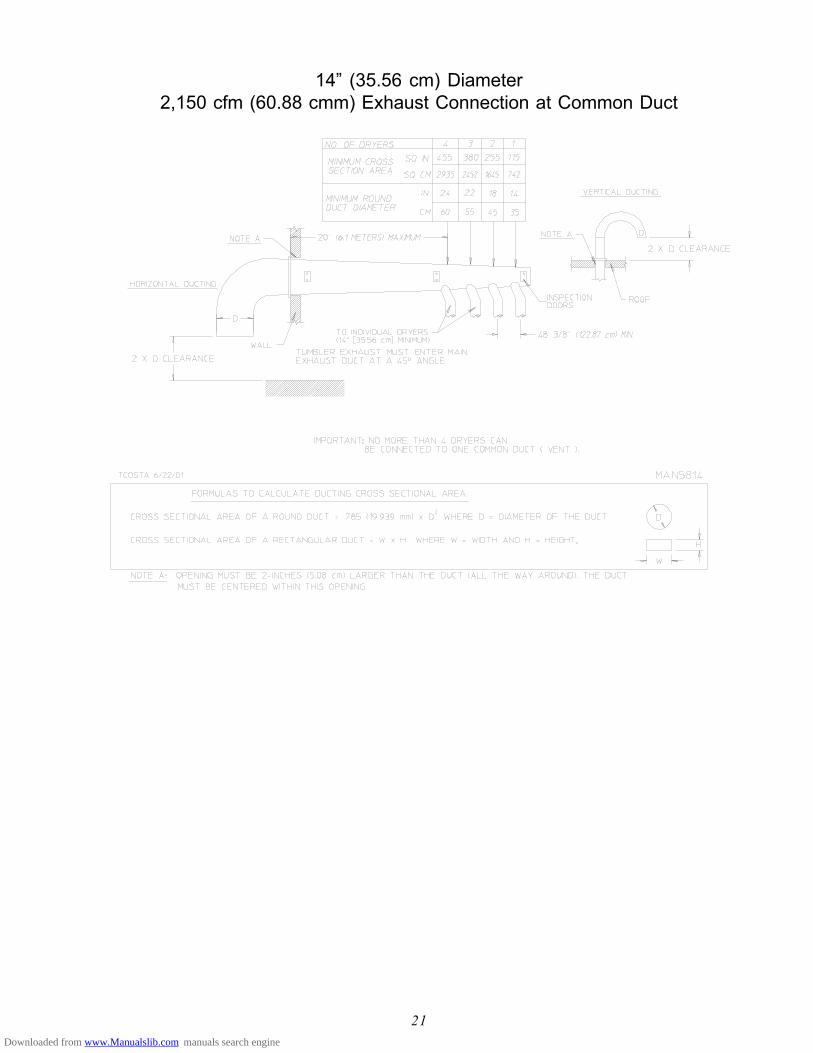
21
14” (35.56 cm) Diameter2,150 cfm (60.88 cmm) Exhaust Connection at Common Duct
Downloaded from www.Manualslib.com manuals search engine

22
F. ELECTRICAL INFORMATION
1. Electrical Requirements
It is your responsibility to have ALL electrical connections made by a properly licensed and competentelectrician to assure that the electrical installation is adequate and conforms to local and state regulations orcodes. In the absence of such codes, ALL electrical connections, material, and workmanship must conformto the applicable requirements of the National Electrical Code ANSI/NFPA NO. 70-LATEST EDITION orin Canada, the Canadian Installation Codes CAN/CGA-B149.1-M91 (Natural Gas) or CAN/CGA-B149.2-M91 (Liquid Propane [L.P.] Gas) or LATEST EDITION.
IMPORTANT: Failure to comply with these codes or ordinances, and/or the requirements stipulatedin this manual can result in personal injury or component failure.
NOTE: Component failure due to improper installation will VOID THE WARRANTY.
Each dryer should be connected to an independently protected branch circuit. The dryer must be connectedwith copper wire only. DO NOT use aluminum wire, which could cause a fire hazard. The copperconductor wire/cable must be of proper ampacity and insulation in accordance with electric codes formaking ALL service connections.
NOTE: The use of aluminum wire will VOID THE WARRANTY.
NOTE: Wiring diagrams are affixed to the left side panel area behind the top control (access) door.
Downloaded from www.Manualslib.com manuals search engine

23
2. Electrical Service Specifications
* AWG Stranded Wire Type...size wire as per National Electrical Code or local codes. 9/4/03** 3-Wire is available.
IMPORTANT: The dryer must be connected to the electric supply shown on the data label that isaffixed to the left side panel/wall area behind the control door. In the case of 208VAC or 230/240 VAC, the supply voltage must match the electric servicespecifications of the data label exactly.
WARNING: 208 VAC AND 230/240 VAC ARE NOT THE SAME. Any damage done to dryercomponents due to improper voltage connections will automatically VOID THEWARRANTY.
NOTE: Manufacturer reserves the right to make changes in specifications at any time without notice orobligation.
ELECTRICAL SERVICE SPECIFICATIONS (PER DRYER) IMPORTANT:
NOTES: A.
B.
C.
208 VAC AND 230/240 VAC ARE NOT THE SAME. When ordering, specify exact voltage.
When fuses are used they must be dual element, time delay, current limiting, class RK1 or RK5 ONLY.Calculate/determine correct fuse value, by applying either local and/or National Electrical Codes to listedappliance amp draw data.Circuit breakers are thermal-magnetic (industrial) motor curve type ONLY. For others, calculate/verify correctbreaker size according to appliance amp draw rating and type of breaker used.Circuit breakers for 3-phase (3Ø) dryers must be 3-pole type.
SERVICEVOLTAGE PHASE WIRE
SERVICE
APPROX.AMP DRAW MINIMUM
WIRE SIZE
FUSING CIRCUITBREAKERDual Element
Time Delay60 Hz 50 Hz 60 Hz 50 Hz 60 Hz 50 Hz
208 3ø 3 14.5 — * 20 — 20 —230/240 3ø 3 14.6 17.4 * 20 25 20 25380-400 3ø 4** — 8.7 * — 15 — 15
416 3ø 4** — 8.4 * — 15 — 15460/480 3ø 3 7.8 — * 15 — 15 —
575 3ø 3 5.8 — * 15 — 15 —
Downloaded from www.Manualslib.com manuals search engine

24
3. Electrical Connections
NOTE: A wiring diagram is included with each dryer and is affixed to the rear upper right guard/panelof the dryer.
The only electrical input connections to the dryer are the 3-phase (3ø) power leads (L1, L2, and L3),GROUND, and in the case of 4 wire service, the neutral. Providing local codes permit, power connectionsto the dryer can be made by the use of a flexible underwriters laboratory listed cord/pigtail (wire size mustconform to rating of the dryer), or the dryer can be hard wired directly to the service breaker. In ALLcases, a strain relief must be used where the wire(s) enter the dryer electrical service (relay) box.
a. Gas Model Dryers
These electrical connections are made at the terminal block located in the electric service/relay box atthe rear, upper left hand corner of the dryer. To gain access into this service box, the service cover(upper back guard) must be removed.
NOTE: A CIRCUIT SERVICING EACH DRYER MUST BE PROVIDED.
Downloaded from www.Manualslib.com manuals search engine

25
4. Grounding
A ground (earth) connection must be provided and installed in accordance with state and local codes. Inthe absence of these codes, grounding must conform to applicable requirements of the National ElectricalCode ANSI/NFPA NO. 70-LATEST EDITION, or in Canada, the installation must conform to applicableCanada Standards: Canadian Electrical Codes Parts 1 & 2 CSA C22.1-1990 or LATEST EDITION. Theground connection may be to a proven earth ground at the location service panel.
NOTE: A grounding connection (terminal lug) is provided in the dryer’s electrical service/relay box atthe rear.
For added personal safety, when possible, it is suggested that a separate ground wire (sized per local codes)be connected from the ground connection of the dryer to a grounded cold water pipe. DO NOT ground toa gas or hot water pipe. The grounded cold water pipe must have metal to metal connections ALL theway to electrical ground. If there are any nonmetallic interruptions, such as a meter, pump, plastic, rubber,or other insulating connectors, they must be jumped out with no. 4 copper wire and securely clamped tobare metal at both ends.
IMPORTANT: For personal safety and proper operation, the dryer must be grounded. For properoperation of the microprocessor controller (computer), an earth (zero) ground isrequired.
NOTE: Grounding via metallic electrical conduit (pipe) is not recommended.
Downloaded from www.Manualslib.com manuals search engine

26
G. GAS INFORMATION
It is your responsibility to have ALL plumbing connections made by a qualified professional to assure that the gasplumbing installation is adequate and conforms to local and state regulations or codes. In the absence of suchcodes, ALL plumbing connections, materials, and workmanship must conform to the applicable requirements ofthe National Fuel Gas Code ANSI Z223.1-LATEST EDITION, or in Canada, the Canadian Installation CodesCAN/CGA-B149.1-M91 (Natural Gas) or CAN/CGA-B149.2-M91 (Liquid Propane [L.P.] Gas) or LATESTEDITION.
IMPORTANT: Failure to comply with these codes or ordinances, and/or the requirementsstipulated in this manual, can result in personal injury and improper operation of thedryer.
The dryer and its individual shutoff valves must be disconnected from the gas supply piping system during anypressure testing of that system at test pressures in excess of 1/2 psig (3.5 kPa). The dryer must be isolatedfrom the gas supply piping system by closing its individual manual shutoff valve during any pressure test of thegas supply system at test pressures equal to or less than 1/2 psig (3.5 kPa).
IMPORTANT: Failure to isolate or disconnect the dryer from supply as noted can cause irreparabledamage to the gas valve VOIDING THE WARRANTY.
WARNING: FIRE OR EXPLOSION COULD RESULT.
1. Gas Supply
The gas dryer installation must meet the American National Standard...National Fuel Gas Code ANSIZ223.1-LATEST EDITION, or in Canada, the Canadian Installation Codes CAN/CGA-B149.1 M91 (NaturalGas) or CAN/CGA-B149.2-M91 (L.P. Gas) or LATEST EDITION, as well as local codes and ordinancesand must be done by a qualified professional.
NOTE: Undersized gas piping will result in ignition problems, slow drying, increased use of energy, andcan create a safety hazard.
The dryer must be connected to the type of heat/gas indicated on the dryer data label affixed to the leftside panel/wall area behind the control door. If this information does not agree with the type of gasavailable, DO NOT operate the dryer. Contact the dealer who sold the dryer or contact the MaytagCo.
IMPORTANT: Any burner changes or conversions must be made by a qualified professional.
The input ratings shown on the dryer data label are for elevations up to 2,000 feet (609.6 meters), unlesselevation requirements of over 2,000 feet (609.6 meters) were specified at the time the dryer order wasplaced with the factory. The adjustment or conversion of dryers in the field for elevations over 2,000 feet(609.6 meters) is made by changing each burner orifice. If this conversion is necessary, contact the dealerwho sold the dryer or contact the Maytag Co.
Downloaded from www.Manualslib.com manuals search engine

27
2. Technical Gas Data
a. Gas Specifications
Shaded areas are stated in metric equivalents
* Measured at outlet side of gas valve pressure tap when gas valve is on.
b. Gas Connections
Inlet connection -------------- 1” N.P.T.Inlet supply size -------------- 1” N.P.T. (minimum)BTU/hr input (per dryer) --- 375,000 (94,500 kcal/hr)
1) Natural Gas
Regulation is controlled by the dryer’s gas valve’s internal regulator. Incoming supply pressuremust be consistent between a minimum of 6.0 inches (14.92 mb) and a maximum of 12.0 inches(29.9 mb) water column (W.C.) pressure.
2) Liquid Propane (L.P.) Gas
Dryers made for use with L.P. gas have the gas valve’s internal pressure regulator blocked open sothat the gas pressure must be regulated upstream of the dryer. The pressure measured at eachgas valve pressure tap must be a consistent 10.5 inches (26.1 mb) water column. There is noregulator or regulation provided in an L.P. dryer. The water column pressure must be regulated atthe source (L.P. tank) or an external regulator must be added to each dryer.
Shaded area is sated in metric equivalent
* Drill Measurement Size (D.M.S.) equivalents are as follows:
Natural Gas .................................. #4 = 0.2090” (5.3086 mm).Liquid Propane Gas ...................... #30 = 0.1285” (3.2639 mm).
NATURAL LIQUID PROPANE
Manifold Pressure* 3.5 inches W.C. 8.7 mb 10.5 inches W.C. 26.1 mb
In-Line Pressure 6.0 - 12.0 inches W.C. 14.92 - 29.9 mb 11.0 inches W.C. 27.4 mb
LiquidPropane
Conversion KitPart Number
Btu/hrRating
kcal/hrRating
Natural Liquid Propane
Qty. D.M.S.* Part No. Qty. D.M.S.* Part No.
375,000 94,500 3 #4 140832 3 #30 140819 880886
Downloaded from www.Manualslib.com manuals search engine

28
3. Piping/Connections
ALL components/materials must conform to National Fuel Gas Code Specifications ANSI Z223.1-LATESTEDITION, or in Canada, CAN/CGA-B149.1-M91 (Natural Gas) or CAN/CGA-B149.2-M91 (LiquidPropane [L.P.] Gas) or LATEST EDITION (for General Installation and Gas Plumbing), as well as localcodes and ordinances and must be done by a qualified professional. It is important that gas pressureregulators meet applicable pressure requirements, and that gas meters be rated for the total amount ofALL the appliance Btus being supplied.
The dryer is provided with a 1” N.P.T. inlet pipe connection extending out the back area of the burner box.The minimum pipe size connection (supply line) to the dryer is 1” N.P.T. For ease of servicing, the gassupply line of each dryer must have its own shutoff valve.
The size of the main gas supply line (header) will vary depending on the distance this line travels from thegas meter or, in the case of L.P. gas, the supply tank, other gas-operated appliances on the same supply line,etc. Specific information regarding supply line size should be determined by the gas supplier.
NOTE: Undersized gas supply piping can create a low or inconsistent pressure, which will result inerratic operation of the burner ignition system.
Consistent gas pressure is essential at ALL gas connections. It is recommended that a 1-inch (2.54 cm)pipe gas loop be installed in the supply line servicing a bank of dryers. An in-line pressure regulator mustbe installed in the gas supply line (header) if the (natural) gas pressure exceeds 12.0 inches (29.9 mb) ofwater column pressure (W.C.).
IMPORTANT: A water column pressure of 3.5 inches (8.7 mb) for natural gas and 10.5 inches (26.1mb) for L.P. dryers is required at the gas valve pressure tap of each dryer for properand safe operation.
A 1/8” N.P.T. plugged tap, accessible for a test gauge connection, must be installed in the main gas supplyline immediately upstream of each dryer.
IMPORTANT: Pipe joint compounds that resist the action of natural and L.P. gases must be used.
IMPORTANT: Test ALL connections for leaks by brushing on a soapy water solution (liquiddetergent works well).
WARNING: NEVER TEST FOR GAS LEAKS WITH A FLAME!!!
ALL components/materials must conform to National Fuel Gas Code Specifications ANSI Z223.1-LATESTEDITION, or in Canada, CAN/CGA-B149.1-M91 (Natural Gas) or CAN/CGA-B149.2-M91 (L.P. Gas)or LATEST EDITION (for General Installation and Gas Plumbing), as well as local codes and ordinancesand must be done by a qualified professional. It is important that gas pressure regulators meet applicablepressure requirements, and that gas meters be rated for the total amount of ALL the appliance Btus beingsupplied.
Downloaded from www.Manualslib.com manuals search engine

29
IMPORTANT: The dryer and its individual shutoff valve must be disconnected from the gas supplypiping system during any pressure testing of that system at test pressures in excess of1/2 psig (3.5 kPa).
NOTE: The dryer must be isolated from the gas supply piping system by closing its individual manualshutoff valve during any pressure testing of the gas supply piping system at test pressures equalto or less than 1/2 psig (3.5 kPa).
Downloaded from www.Manualslib.com manuals search engine

30
H. PREPARATION FOR OPERATION
The following items should be checked before attempting to operate the dryer:
1. Read ALL “CAUTION,” “WARNING,” and “DIRECTION” labels attached to the dryer.
2. Check incoming supply voltage to be sure that it is the same as indicated on the dryer data label affixed tothe left side panel/wall area behind the control door as shown on page 8. In case of 208 VAC or 230/240VAC, the supply voltage must match the electric service exactly.
3. GAS MODELS - check to assure that the dryer is connected to the type of heat/gas indicated on the dryerdata label.
4. GAS MODELS - the sail switch damper assembly was installed and adjusted at the factory prior toshipping. However, each sail switch adjustment must be checked to assure that this important safetycontrol is functioning.
5. GAS MODELS - be sure that ALL gas shutoff valves are in the open position.
6. Be sure ALL back panels (guards) and electric box covers have been replaced.
7. Check ALL service doors to assure that they are closed and secured in place.
8. Be sure lint drawer is securely in place.
NOTE: LINT DRAWER MUST BE ALL THE WAY IN PLACE TO ACTIVATE SAFETYSWITCH OTHERWISE THE DRYER WILL NOT START.
9. Rotate the basket (tumbler) by hand to be sure it moves freely.
10. Check bolts, nuts, screws, terminals, and fittings for security.
11. Check basket (tumbler) bearing setscrews to insure they are ALL tight.
Downloaded from www.Manualslib.com manuals search engine

31
I. PREOPERATIONAL TESTS
ALL dryers are thoroughly tested and inspected before leaving the factory. However, a preoperational testshould be performed before the dryer is publicly used. It is possible that adjustments have changed in transit ordue to marginal location (installation) conditions.
1. To start the dryer:
a. Microprocessor Controller (Computer) Dryers...
1) Light emitting diode (L.E.D.) display will read “REAdY” (meaning no cycle in progress).
2) Press the letter on the keyboard (touch pad) corresponding to the cycle desired (i.e., key “E”)...
a) The dryer will then start (rotate).
3) L.E.D. display will now show “Cycle In Progress” and “Cycle Status” meaning that the dryer is inthe drying cycle (dry mode for 30 minutes) and count downwards in minutes.
NOTE: Pressing keyboard (touch pad) key “A,” “B,” “C,” “D,” or “F,” will also start the dryer. Thesix (6) preprogrammed drying cycles “A” through “F” have been stored in the microprocessorcontroller’s (computer’s) memory. Refer to the Programming Manual supplied with the dryerfor more specific operating instructions.
NOTE: The dryer can be stopped at any time by opening the main door or by pressing the “STOP”red key. To restart the dryer, press the “START” green key or a preprogrammed cyclekey (i.e., “E”).
NOTE: Selection (settings) changes can be made at any time during the drying cycle by pressing the“STOP” red key twice. The L.E.D. display will return to “REAdY” at which time anew cycle selection can be made.
2. Check to insure that the basket (tumbler) starts in the clockwise (CW) direction. Additionally, check thedirection of the blower motor (impellor/fan) to insure that blower motor (impellor/fan) rotates in the clockwise(CW) direction as viewed from the front. If it is, the phasing is correct. If the phasing is incorrect, reversetwo (2) of the leads at L1, L2, or L3 of the power supply connections made to the dryer.
IMPORTANT: Dryer blower motor (impellor/fan) as viewed from the front must turn in the clockwise(CW) direction, otherwise dryer efficiency will be drastically reduced and prematurecomponent failure can result.
3. Heat Circuit Operational Test
a. Gas Models
1) When the dryer is first started (during initial start-up), the burner has a tendency not to ignite on thefirst attempt. This is because the gas supply piping is filled with air, so it may take a few minutes forthis air to be purged.
Press and hold thestop/clear key
4: DEFAULTSETTINGS
4
Nextpage
Or number
Downloaded from www.Manualslib.com manuals search engine

32
2) The dryer is equipped with a Direct Spark Ignition (DSI) system, which has internal diagnostics. Ifignition is not established after the first attempt, the heat circuit DSI module will “LOCKOUT” untilit is manually reset. To reset the DSI system, open and close main door and restart dryer (press the“ENTER/START” key).
NOTE: During the purging period, check to be sure that ALL gas shutoff valves are open.
3) Once ignition is established, a gas pressure test should be taken at the gas valve pressure tap ofeach dryer to assure that the water column (W.C.) pressure is correct and consistent.
NOTE: Water column pressure requirements (measured at the gas valve pressure tap)...
Natural Gas ---------------------- 3.5 inches (8.7 mb) water column.Liquid Propane (L.P.) Gas ----- 10.5 inches (26.1 mb) water column.
IMPORTANT: There is no regulator provided in an L.P. dryer. The water column pressure must beregulated at the source (L.P. tank) or an external regulator must be added to eachdryer.
4. Make a complete operational check of ALL safety-related circuits (i.e., lint drawer switch and sail switchon gas models).
NOTE: To check for proper sail switch operation, open the main door and while holding main doorswitch plunger in, start dryer. Dryer should start but heat circuit should not be activated (on).If heat (burner) does activate, shut the dryer off and make necessary adjustments.
5. A reversing basket (tumbler) dryer should never be operated with less than a 85 lb (38 kg) load (dryweight). The size of the load will affect the coast-down and dwell (stop) times. The basket (tumbler) mustcome to a complete stop before starting in the opposite direction.
a. Microprocessor Controller (Computer) Dryer Models
1) Spin and dwell (stop) times are not adjustable in the Automatic Mode and have been preprogrammedinto the microprocessor controller (computer) for a 120-second spin time and a 5-second dwell(stop) time.
2) Spin and dwell (stop) times are adjustable in the Manual (Timed) Mode.
b. Dual Timer Dryer Models...
1) Spin and dwell (stop) times are adjustable at the reversing timer.
BASKET (TUMBLER) COATING
The basket (tumbler) is treated with a protective coating. We suggest dampening old garments or cloth materialwith a solution of water and nonflammable mild detergent and tumbling them in the basket (tumbler) to removethis coating.
6. Each dryer should be operated through one (1) complete cycle to assure that no further adjustments arenecessary and that ALL components are functioning properly.
Downloaded from www.Manualslib.com manuals search engine

33
7. Make a complete operational check of ALL operating controls.
a. Microprocessor Controller (Computer) Programs and Selections...
1) Each microprocessor controller (computer) has been preprogrammed by the factory with the mostcommonly used parameter (program) selections. If computer program changes are required, referto the computer programming manual, which was shipped with the dryer.
b. Dual Timer Dryers Check...
1) Heating Timer
2) Cool Down Timer
3) Temperature Selection Functions
J. SHUTDOWN INSTRUCTIONS
If the dryer is to be shutdown (taken out of service) for a period of time, the following must be performed:
1. Discontinue power to the dryer either at the external disconnect switch or the circuit breaker.
2. Discontinue the gas or steam supply:
a. GAS MODELS...discontinue the gas supply.
1) SHUT OFF external gas supply shutoff valve.
2) SHUT OFF internal gas supply shutoff valve located in the gas valve burner area.
Downloaded from www.Manualslib.com manuals search engine

34
K. OPERATING INSTRUCTIONS
NOTE: Before attempting to start the dryer make sure that the main door is closed and the lint draweris securely in place.
1. To start the dryer:
a. Microprocessor Controller (Computer) Dryers...
1) Light emitting diode (L.E.D.) display will read “REAdY” (meaning no cycle in progress).
2) Press the letter on the keyboard (touch pad) corresponding to the cycle desired (i.e., key “E”)...
a) The dryer will then start (rotate).
3) L.E.D. display will now show the “Cycle In Progress” and “Cycle Status” meaning that the dryeris in the drying cycle (dry mode for 30 minutes) and count downwards in minutes.
NOTE: Pressing keyboard (touch pad) key “A,” “B,” “C,” “D,” or “F” will also start the dryer. Thesix (6) preprogrammed drying cycles “A” through “F” have been stored in the microprocessorcontroller’s (computer’s) memory. Refer to the Programming Manual supplied with the dryerfor more specific operating instructions.
NOTE: The dryer can be stopped at any time by opening the main door or by pressing the “STOP”red key. To restart the dryer, press the “START” green key or a preprogrammed cyclekey (i.e., “E”).
NOTE: Selection (settings) changes can be made at any time during the drying cycle by pressing the“STOP” red key twice. The L.E.D. display will return to “REAdY” at which time anew cycle selection can be made.
b. Dual Timer Dryer Models...
1) Select drying time and cool down time desired...
a) Turn heat timer clockwise (CW) to desired time (i.e., 1 minute to 60 minutes).
b) Turn cool down timer clockwise (CW) to desired time (i.e., 0 minutes to 15 minutes).
2) Select drying temperature.
3) Push “Start” button...
a) Dryer will now start.
4) To stop dryer, open the main door.
Downloaded from www.Manualslib.com manuals search engine

35
SECTION IVSERVICE/PARTS INFORMATION
A. SERVICE
1. Service must be performed by a qualified trained technician, service agency, or gas supplier. If service isrequired, contact the dealer from whom the Maytag equipment was purchased. If the dealer cannot becontacted or is unknown, contact the Maytag Co. for a dealer in your area.
NOTE: When contacting the Maytag Co., be sure to give them the correct model number andserial number so that your inquiry is handled in an expeditious manner.
B. PARTS
1. Replacement parts should be purchased from the dealer from whom the Maytag equipment was purchased.If the Maytag dealer cannot be contacted or is unknown, contact the Maytag Co. for a dealer in yourarea.
NOTE: When ordering replacement parts from the Maytag dealer or the Maytag Co. be sure to givethem the correct model number and serial number so that your parts order can beprocessed in an expeditious manner.
Downloaded from www.Manualslib.com manuals search engine

36
SECTION VWARRANTY INFORMATION
A. RETURNING WARRANTY CARDS
1. Before any dryer leaves the manufacturer’s test area, a warranty card is placed on the back side of themain door glass. These warranty cards are intended to serve the customer where we record the individualinstallation date and warranty information to better serve you should you file a warranty claim.
IMPORTANT: A separate warranty card must be completed and returned for each individual dryer.
NOTE: Be sure to include the installation date when returning the warranty card(s).
B. WARRANTY
For a copy of the manufacturer’s commercial warranty covering your particular dryer(s), contact the Maytagdealer from whom you purchased the equipment and request a dryer warranty form. If the dealer cannot becontacted or is unknown, warranty information can be obtained from the Maytag Co.
NOTE: Whenever contacting the Maytag Co. for warranty information, be sure to have the dryer’smodel number and serial number available so that your inquiry can be handled in anexpeditious manner.
Downloaded from www.Manualslib.com manuals search engine

37
SECTION VIROUTINE MAINTENANCE
A. CLEANING
A program and/or schedule should be established for periodic inspection, cleaning, and removal of lint fromvarious areas of the dryer, as well as throughout the ductwork system. The frequency of cleaning can best bedetermined from experience at each location. Maximum operating efficiency is dependent upon proper aircirculation. The accumulation of lint can restrict this airflow. If the guidelines in this section are met, a Maytagdryer will provide many years of efficient, trouble free, and most importantly, safe operation.
WARNING: LINT FROM MOST FABRICS IS HIGHLY COMBUSTIBLE. THEACCUMULATION OF LINT CAN CREATE A POTENTIAL FIRE HAZARD.
WARNING: KEEP DRYER AREA CLEAR AND FREE FROM COMBUSTIBLEMATERIALS, GASOLINE, AND OTHER FLAMMABLE VAPORS ANDLIQUIDS.
NOTE: Suggested time intervals shown are for average usage which is considered six (6) to eight (8)operational (running) hours per day.
IMPORTANT: Dryer produces combustible lint and must be exhausted to the outdoors. Every 6months, inspect the exhaust ducting and remove any lint build up.
CLEAN THE LINT DRAWER/SCREEN EVERY THIRD OR FOURTH LOAD.
NOTE: Frequency can best be determined at each location.
SUGGESTED CLEANING SCHEDULE
DAILY (beginning of each work shift)
1. Clean lint from screen.
2. Inspect lint screen and replace if torn.
WEEKLY
Clean lint accumulation from lint chamber, thermostat, and microprocessor temperature sensor (sensor bracket)area.
WARNING: TO AVOID THE HAZARD OF ELECTRICAL SHOCK, DISCONTINUEELECTRICAL SUPPLY TO THE DRYER.
Downloaded from www.Manualslib.com manuals search engine

38
90 DAYS
Remove lint from around basket (tumbler), drive motors, and surrounding areas. Remove lint from gas valveburner area with a dusting brush or vacuum cleaner attachment.
NOTE: To prevent damage, avoid cleaning and/or touching ignitor/flame-probe assembly.
Remove lint accumulation from inside control box and at the rear area behind control box.
6 MONTHS
Inspect and remove lint accumulation in customer furnished exhaust ductwork system and from dryer’s internalexhaust ducting.
Blower motor (impellor/fan) belts and drive belts should be examined. Cracked and/or seriously frayed beltsshould be replaced. Tighten belts when necessary.
WARNING: THE ACCUMULATION OF LINT IN THE EXHAUST DUCTWORK CANCREATE A POTENTIAL FIRE HAZARD.
WARNING: DO NOT OBSTRUCT THE FLOW OF COMBUSTION AND VENTILATIONAIR. CHECK CUSTOMER FURNISHED BACK DRAFTED DAMPERS INEXHAUST DUCTWORK. INSPECT AND REMOVE ANY LINTACCUMULATION, WHICH CAN CAUSE DAMPER TO BIND OR STICK.
NOTE: A back draft damper that is sticking partially closed can result in slow drying and shutdown ofthe heat circuit safety switches or thermostats.
NOTE: When cleaning dryer cabinet(s), avoid using harsh abrasives. A product intended for thecleaning of appliances is recommended.
Downloaded from www.Manualslib.com manuals search engine

39
B. ADJUSTMENTS
7 DAYS AFTER INSTALLATION AND EVERY 6 MONTHS THEREAFTER
Inspect bolts, nuts, screws (bearing setscrews), grounding connections, and nonpermanent gas connections(unions, shutoff valves, and orifices). Motor and drive belts should be examined. Cracked or seriously frayedbelts should be replaced. Tighten loose V-belts when necessary. Complete operational check of controls andvalves. Complete operational check of ALL safety devices (door switch, lint drawer switch, sail switch, burner,and hi-limit thermostats).
C. LUBRICATION
The motor bearings and under normal/most conditions the basket (tumbler) and idler bearings are permanentlylubricated. It is physically possible to relubricate the basket (tumbler) and idler bearings if you choose to do soeven though this practice is not necessary. Use Shell Alvania #2 or its equivalent. The basket (tumbler) and idlerbearings used in the dryer DO NOT have a grease fitting. Provisions are made in the bearing housing for theaddition of a grease fitting which can be obtained elsewhere, or from the Maytag dealer by ordering kit Part No.882159 (basket [tumbler] ONLY), which includes two (2) fittings.
Downloaded from www.Manualslib.com manuals search engine

40
SECTION VIIDATA LABEL INFORMATION
A. DATA LABEL
Contact Maytag Co.
When contacting Maytag, certain information is required to insure proper service/parts information from Maytag.This information is on the data label affixed to the left side panel/wall area behind the control door. Whencontacting Maytag, please have the model number and serial number available.
Downloaded from www.Manualslib.com manuals search engine

41
THE DATA LABEL
1. MODEL NUMBERThe model number is an Maytag Company number, which describes the size of thedryer and the type of heat (gas, electric, or steam).
2. SERIAL NUMBERThe serial number allows Maytag to gather information on your particular dryer.
3. MANUFACTURING CODE NUMBERThe manufacturing code number is a number issued by the manufacturer, whichdescribes ALL possible options on your particular model.
4. TYPE OF HEATThis describes the type of heat for your particular dryer: gas (either natural gas orliquid propane [L.P.] gas), electric, or steam.
5. HEAT INPUT (for GAS DRYERS)This describes the heat input in British Thermal Units per Hour (Btu/hr).
6. ORIFICE SIZE (for GAS DRYERS)Gives the number drill size used.
7. ELECTRIC SERVICEThis describes the electric service for your particular model.
8. GAS MANIFOLD PRESSURE (for GAS DRYERS)This describes the manifold pressure taken at the gas valve tap.
9. APPLICABLE APPROVAL SEAL(S)I.E., Canadian Standards Association International.
Downloaded from www.Manualslib.com manuals search engine

42
SECTION VIIIREVERSING TIMER SPIN/DWELL ADJUSTMENTS
Timer models have an electric reversing timer in the electric service box, which is located in the upper left reararea of the dryer.
Both the dwell (stop) time and basket (tumbler) spin time are adjustable by mode selection switches located onthe electronic timer (refer to the illustration below).
SPIN TIME
Adjustment Position Number 1 2 3 4 5
Time in Seconds* 30 60 90 120 150
DWELL (STOP) TIME
Adjustment Position Number 1 2 3 4 5
Time in Seconds* 5 6.3 7.6 8.9 10.2
* Values shown are +/- 1-second.
Downloaded from www.Manualslib.com manuals search engine

43
SECTION IXPROCEDURE FOR FUNCTIONAL CHECK
OF REPLACEMENT COMPONENTS
1. Microprocessor Controller (Computer) Board
a. Upon completing installation of the replacement microprocessor controller (computer) board, reestablishpower to the dryer.
b. Start the drying cycle by pressing any of the preset cycles in letters A-F.
c. Verify that the applicable indicator lights on the back side of the microprocessor controller (computer)board are lit. (Refer to the illustration below.)
Downloaded from www.Manualslib.com manuals search engine

44
2. For Models With Johnson Controls Direct Spark Ignition (DSI) Module (G760)
Theory Of Operation:
Start the drying cycle. When the gas burnerignites within the chosen trial for ignition time(6-seconds), the flame sensor detects gas burnerflame and signals the DSI module to keep thegas valve open...as long as there is a call forheat. The DSI module will “LOCKOUT” ifthe gas burner flame is not sensed at the end ofthe trial for ignition period. The trial for ignitionperiod will be repeated for a total of three (3)retries/trials (the initial try and two [2] moreretries/trials). If the flame is not sensed at theend of the third retry/trial (inter-purge period of30-seconds) the DSI module will “LOCKOUT”L.E.D. flashes).
A steady L.E.D. indicator indicates normaloperation.
No L.E.D. indicator indicates a power or aninternal failure has occurred.
Downloaded from www.Manualslib.com manuals search engine

45
The exclusive Sensor Activated Fire Extinguishing (S.A.F.E.) System will extinguish firesthat may start in the drying basket (tumbler). A series of sensors positioned throughoutthe basket (tumbler) and interfaced with the microprocessor will trigger the S.A.F.E.system water jet(s) to quickly extinguish the flames. The water jet(s) remain on for 2minutes and will automatically activate again if a fire condition remains or reignites. Whilethe water jet(s) are activated, the basket (tumbler) will jog to move the water throughoutthe load. The microprocessor will display that the system was activated and will continueto display until the dryer is attended to.
We have tried to make this manual as complete as possible and hope you will find ituseful. ADC reserves the right to make changes from time to time, without notice orobligation, in prices, specifications, colors, and material, and to change or discontinuemodels.
S.A.F.E. System In Action
SECTION XSENSOR ACTIVATED
FIRE EXTINGUISHING (S.A.F.E.) SYSTEM
Downloaded from www.Manualslib.com manuals search engine

46
BEFORE YOU START!
CHECK LOCAL CODES AND PERMITS
Call your local water company or the proper municipal authority for information regarding local codes.
IMPORTANT: It is your responsibility to have ALL plumbing connections made by a qualifiedprofessional to assure that the plumbing installation is adequate and conforms to local,state, and federal regulations or codes.
IMPORTANT: It is the installation or owners responsibility to see that the necessary or requiredwater, water pressure, pipe size, or connections are provided. Manufacturer assumesno responsibility if the Sensor Activated Fire Extinguishing (S.A.F.E.) System is notconnected, installed, or maintained properly.
INSTALLATION
1. Requirements
The S.A.F.E. system must be supplied with a minimum water pipe size of 1/2” and be provided with 40 psi+/- 20 psi (2.75 bar +/- 1.37 bar) of pressure. For use of optional manual bypass, a second source with thesame piping and pressure requirements is required.
Flexible 1/2 feeds must be provided to avoid damage to electric water solenoid valve by vibration.
IMPORTANT: Flexible supply line/coupling must be used. Solenoid valve failure due to hardplumbing connections WILL VOID WARRANTY.
If the rear area of the dryer, or the water supply is located in an area where it will be exposed to cold/freezing temperatures, provisions must be made to protect these water lines from freezing.
WARNING: If the water in the supply line or water solenoid valve freezes, the S.A.F.E. system willbe INOPERATIVE!!
IMPORTANT: Appliance is to be connected to the water mains using a new hose-set and the oldhose-sets should not be reused.
Downloaded from www.Manualslib.com manuals search engine

47
2. Water Connections:
The water connection is made to the 3/4”-11.5 NHhose adapter of the electric water solenoid valve,located at the rear upper midsection of the dryer (referto the photo).
The water solenoid valve has a 3/8” M.P.T. connectionsupplied with a 3/4”-11.5 NH hose adapter to providethe minimum 1/2-inch supply (feed) line. Flexiblesupply line/coupling must be used in an effort toavoid damaging the electric water solenoid valve.
NOTE: The 3/4”-11.5 NH is a standard hose coupling screw thread. It is not to be confused with3/4” N.P.T. The sealing of an NH connection is made with a washer opposed to the matingthreads of an N.P.T. assembly. The two (2) thread designs are not compatible.
IMPORTANT: Flexible supply line/coupling must be used. Solenoid valve failure due to hardplumbing connections WILL VOID WARRANTY. It is recommended that a filteror strainer be installed in the water supply line.
Typical water supply...
Downloaded from www.Manualslib.com manuals search engine

48
OPTIONAL MANUAL BYPASS
Provisions are made in the dryer Sensor Activated Fire Extinguishing (S.A.F.E.) system for the installation of anoptional manual bypass. Depending on the model dryer, the connections for the manual bypass are made at the“T” or “four way” fitting located in the outlet supply side of the water solenoid valve. The use and connectionsof this manual bypass are at the option or discretion of the owner.
The water connection for the manual bypass is made to the “T” or “four way” fitting which has a 3/8” F.P.T. anda coupling must be used to provide the minimum 1/2” supply (feed) line.
If the rear area of the dryer, or the water supply is located in an area where it will be exposed to cold/freezingtemperatures, provisions must be made to protect these water lines from freezing.
WARNING: If the water in the supply line or water solenoid valve freezes, the S.A.F.E. system willbe INOPERATIVE!!
The manual ball cock shutoff valve must be located outside of the dryer at a distance from the dryer where itis easily accessible.
3. Electrical Requirements
No independent external power source or supply connection is necessary. The 24 volt power to operate theS.A.F.E. system is accomplished internally in the dryer (from the dryer controls).
WARNING: Electrical power must be provided to the dryer at ALL times. If the main electricalpower supply to the dryer is disconnected, the S.A.F.E. system is INOPERATIVE!!
Downloaded from www.Manualslib.com manuals search engine

49
Sensor ActivatedFire Extinguishing (S.A.F.E.) System
Theory of OperationWhile the dryer is in an idle state or 20-seconds after the heat turns off, the Phase 7 control monitors theS.A.F.E. system probe located in the top of the basket (tumbler) chamber and records the minimum temperature.If the minimum recorded S.A.F.E. system probe temperature is no less than 120° F (48° C) and the controldetects a 50° rise in temperature, this will be the trip point and the S.A.F.E. system routine will activate.
While a drying cycle is in process and the heat has turned on at least once, the Phase 7 control monitors theexhaust temperature transducer. If the drying cycle temperature set point is set greater than 160° F (71° C) andthe control detects an exhaust temperature rise 25° F greater than set point, this will be the trip point and theS.A.F.E. system routine will activate. If set point is below 160° F (71° C) the trip point will be 185° F (85° C).
Once the S.A.F.E. system routine is activated, water will be injected into the basket (tumbler) chamber. Anytimewater is being injected into the basket (tumbler); the basket (tumbler) drive will turn the load for 1-second every15-seconds. This process will continue for a minimum of 2 minutes. After 2 minutes has elapsed, the control willcheck if the temperature remained above trip point, if so water will remain on. The control will continue to checkif temperature is above trip point every 30-seconds. If the water has been on for a constant 10 minutes, thewater will be turned off regardless of the temperature. If the temperature has dropped below trip point, thecontrol will turn off the water prior to 10 minutes.
SYSTEM RESET
After the microprocessor determines that the situation is under control and shuts the water being injected into thebasket (tumbler) off, the microprocessor display will read “S.A.F.E. System activated,” and the horn/tone willsound until reset manually.
To reset the microprocessor once the control displays “S.A.F.E. System activated,” press the red key on thekeyboard (touch pad).
NON-COIN S.A.F.E. SYSTEM CHECK PROCEDURE
The operation of the water solenoid valve can be tested to insure that the water supply system and valve arefunctional. Before attempting system check, be sure that ALL water supply shutoff valves to the dryer are inthe OPEN position, and the dryer must be in the “READY” mode where no cycle is loaded or in progress.
The procedure is as follows:
1. Press and hold the RED STOP key (while in “READY” mode and no cycle in progress).
2. Press and hold the “A” key.
3. Water valve will open and water will be dispensed into basket (tumbler) area as long as both keys are held.
IMPORTANT: This is a test function only and the keys should be held and system activated for onlya second or so, otherwise water will accumulate in various places in the dryer.
Downloaded from www.Manualslib.com manuals search engine

50
Sensor ActivatedFire Extinguishing (S.A.F.E.) System
Parts Break DownReplacement parts can be obtained from your reseller or the ADC factory. When ordering replacement partsfrom the factory, you can FAX your order to ADC at (508) 678-9447 or telephone your order directly to theADC Parts Department at (508) 678-9000. Please specify the dryer model number and serial number inaddition to the description and part number, so that your order is processed accurately and promptly.
The illustrations on the following pages may not depict your particular dryer exactly. The illustrations arecomposite of the various dryer models. Be sure to check the descriptions of the parts thoroughly before ordering.
We have tried to make this manual as complete as possible and hope you will find it useful. ADC reserves theright to make changes from time to time, without notice or obligation, in prices, specifications, colors, and material,and to change or discontinue models.
Illus. No. Part No. Qty. Description
1 165114 1 S.A.F.E. System Solenoid Valve 24V 50/60 Hz2 143220 1 3/8” F.P.T. Brass Tee3 143251 1 3/8” M.P.T. Brass Plug4 143208 2 3/8” Comp x 3/8” M.P.T. Brass Connector5 143108 1 20” Long Stainless Steel Flexible Tubing6 311588 1 Sprinkler Head Mounting Plate7 143303 1 3/8” N.P.T. Brass Lock Nut8 143301 1 3/8” Brass 45° Elbow9 150309 2 #10-16 x 1/2” Hex Head TEK Crimptite Screw10 150301 2 #8-18 x 7/16” Phillips Pan Head TEK Screw11 143581 1 3 GPM 3/8” F.P.T. Spray Nozzle12 143025 1 3/4”-11.5 NH x 3/8” N.P.T. Hose Adapter13 824081 1 R.C. Network Assembly
Downloaded from www.Manualslib.com manuals search engine

51
Illus. No. Part No. Qty. Description
1 822752 1 S.A.F.E. System Temperature Probe Assembly(includes illus. nos. 1 through 5)
2 154007 2 Push On Fastener3 390390 1 Sensor Bracket ONLY4 150301 2 #8-18 x 7/16” Phillips Pan Head TEK Screw5 122647 1 Connector ONLY
(does not include terminals)
Downloaded from www.Manualslib.com manuals search engine

Maytag 113395 1 - 01/06/03-25 2 * 09/03/03-25
Downloaded from www.Manualslib.com manuals search engine