mdot its design manual
TRANSCRIPT

ITS Design Manual Overview
Purpose• So designers can create concept to
complete plan set and spec package for MDOT ITS projects or other municipal ITS projects.
• Uniform guidelines and design criteria for ITS elements implemented on MS urban freeways, rural freeways, urban arterials and rural roadways.
• Manual doesn’t address specific details designers encounter, so must confirm assumptions with ITS Program Manager.
Typical ITS design elements• Electrical power location• Fiber optic communications infrastructure• Dynamic Message Signs (DMS) • Closed-Circuit Television (CCTV) system • Radar Detection System (RDS)• Video Detection System (VDS)• Road Weather Information System (RWIS)• Highway Advisory Radio (HAR)• Communications Hut building and equipment • Transportation Management Center (TMC)
equipment
Design Manual Organization• 1 – Introduction• 2 – General Design Guidelines• 3 – Power Source Design and Placement• 4 – ITS Communications Design• 5 – Dynamic Message Sign Design• 6 – Closed Circuit Television System (CCTV) Design• 7 – Radar Detection System Design• 8 – Video Detection System (VDS) Design• 9 – ROAD Weather Information System Design• 10 – Highway Advisory Radio Design• 11 – HUT Building Design• 12 – HUT Equipment Design• 13 – Traffic Management Center Design• 14 - Smart Work Zones• 15 – PS&E Assembly for ITS Projects• 16 – Appendices
Introduction • Project Development Process • Use SEMP for SEA then Design Manual
for plan development• SEMP refers to project development
process: • 1) Develop Concept of Operations• 2) Develop system requirements• 3) Develop Project SEA• 4) Detailed Design – this manual
• Steps in Chapter 14 – key are design concept and SEA
General design guidelines
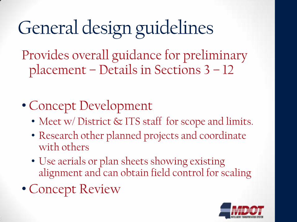
Provides overall guidance for preliminary placement – Details in Sections 3 – 12
• Concept Development • Meet w/ District & ITS staff for scope and limits.
• Research other planned projects and coordinate with others
• Use aerials or plan sheets showing existing alignment and can obtain field control for scaling
• Concept Review
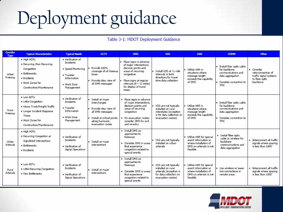
Deployment guidance
7
General design guidelines steps
• General Device Placement
• Before Field Visit
• While On Field Visit
• Guardrail Considerations
Power Source Design
• Starts in Concept phase
• Early Coordination Required
• What to show on plans
• What are demarcation locations
• When you may need transformer
• Urban vs. Rural area Considerations
• Verify obstacles for routing
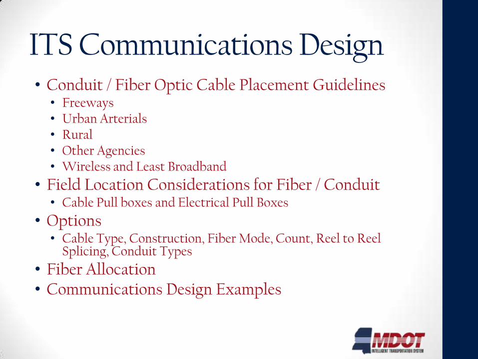
ITS Communications Design• Conduit / Fiber Optic Cable Placement Guidelines
• Freeways• Urban Arterials• Rural• Other Agencies• Wireless and Least Broadband
• Field Location Considerations for Fiber / Conduit• Cable Pull boxes and Electrical Pull Boxes
• Options• Cable Type, Construction, Fiber Mode, Count, Reel to Reel
Splicing, Conduit Types
• Fiber Allocation • Communications Design Examples
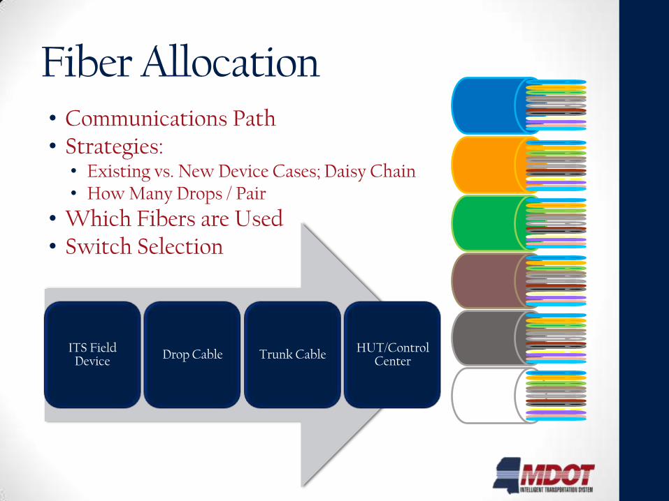
Fiber Allocation• Communications Path• Strategies:
• Existing vs. New Device Cases; Daisy Chain• How Many Drops / Pair
• Which Fibers are Used• Switch Selection
ITS Field Device
Drop Cable Trunk CableHUT/Control
Center
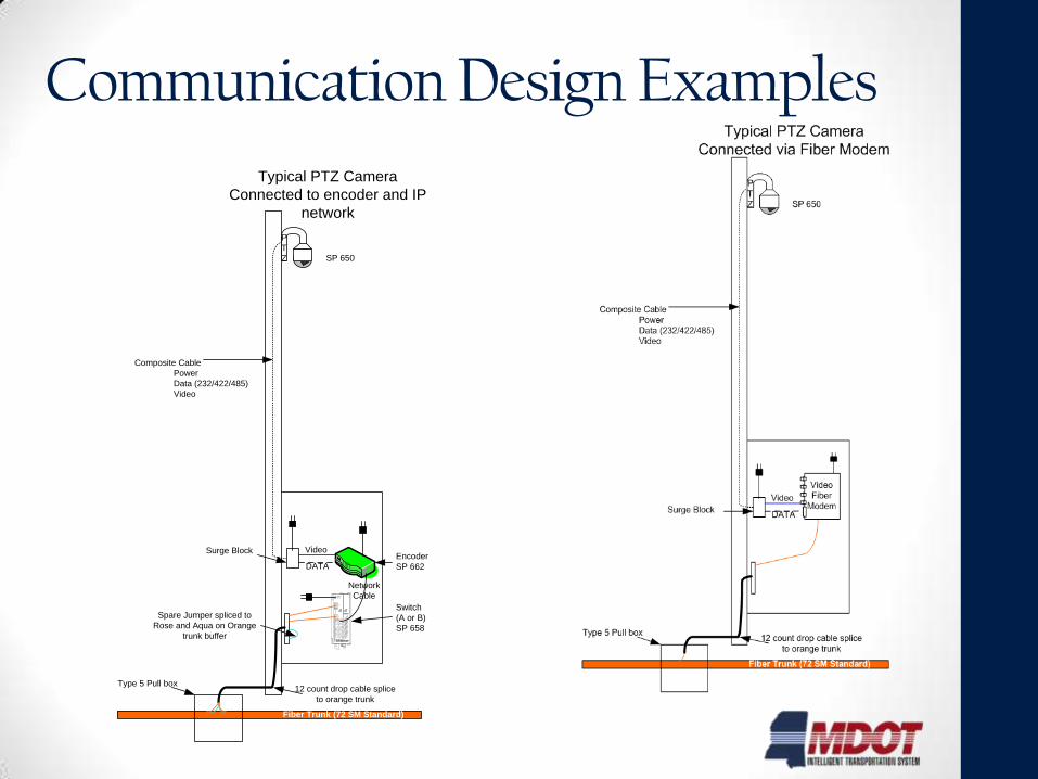
Communication Design Examples
P
T
Z
Typical PTZ Camera
Connected to encoder and IP
network
Composite Cable
Power
Data (232/422/485)
Video
Surge Block
Network
Cable
Video
DATA
Fiber Trunk (72 SM Standard)
Encoder
SP 662
Switch
(A or B)
SP 658
Type 5 Pull box12 count drop cable splice
to orange trunk
Spare Jumper spliced to
Rose and Aqua on Orange
trunk buffer
SP 650
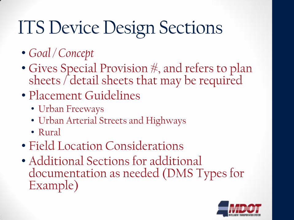
ITS Device Design Sections• Goal / Concept• Gives Special Provision #, and refers to plan
sheets / detail sheets that may be required• Placement Guidelines
• Urban Freeways • Urban Arterial Streets and Highways• Rural
• Field Location Considerations• Additional Sections for additional
documentation as needed (DMS Types for Example)
TMC Design
• Equipment Room Layout
• Equipment Rack Elevations and Equipment Interconnections
• Operations Area Layout
• Electrical and Environmental Infrastructure
• Construction Coordination

Smart Work Zones
• Guidelines and Process
• Special Provisions
PS&E Assembly • Includes plans, standard specs, all special provisions,
NTBs, construction cost estimates, all approved agreements with railroads, utilities, and municipalities, the proposal assembly and the utility and ROW certificates.
• Ch 15 of Roadway Design Manual• Typical Workflow• Contract Plans• Specs
• Special Provisions• NTBs
• Cost Estimates• ITS-Related Permits & MOAs/MOUs

ROADWAY/BRIDGE DESIGN TASKS ITS DESIGN TASKS
PHASE A: RIGHT-OF-WAY PLANS SYSTEMS ENGINEERING & PRELIMINARY ITS PLANS
Attend Roadway/Bridge Scoping Meeting Attend ITS Scoping Meeting w/ ITS Program Director
Prepare/Submit Conceptual Plans Prepare/Submit Draft Systems Engineering Analysis (SEA)
Attend Conceptual Plans Review Meeting Prepare/Submit Draft Preliminary (50%) ITS Plans *,
Specifications List and Planning-Level Const. Cost Estimate
Prepare/Submit Preliminary R.O.W. Plans Attend Review Meeting w/ ITS Program Director
Prepare/Submit Field Inspection Plans Prepare/Submit Final SEA & Preliminary (50%) ITS Plans *,
Specifications List and Planning-Level Const. Cost Estimate
Attend Field Inspection Coordinate with ITS Program Director to develop all required
permits (e.g., rail crossings) and MOUs with other agencies
Prepare/Submit Final R.O.W. Plans
PHASE B: CONTRACT PLANS FINAL ITS PLANS & SPECIFICATIONS
Attend Roadway/Bridge Design Conference
Prepare/Submit Office Review Plans Prepare/Submit ITS Office Review Plans, Specs. & Estimate
(95% Submittal)
Attend Roadway/Bridge Office Review Attend ITS Office Review w/ ITS Program Director
Prepare/Submit Final Contract Plans
(Roadway/Bridge PS&E Assembly)
Prepare/Submit Final ITS Plans *, Specifications & Estimate
(PS&E Assembly)
If above tasks are not completed in conjunction with Phase A: Right-of-Way Plans, the designer shall complete within first 90 days of Phase B.
If a stand-alone ITS project, the designer shall complete all tasks in accordance with the mutually agreed project schedule.
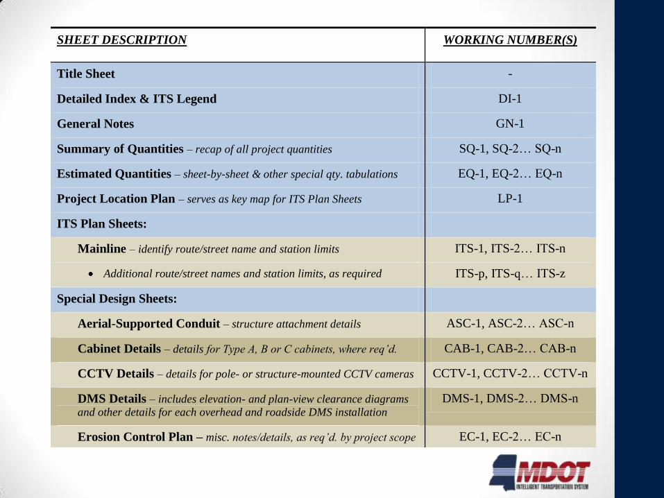
SHEET DESCRIPTION WORKING NUMBER(S)
Title Sheet -
Detailed Index & ITS Legend DI-1
General Notes GN-1
Summary of Quantities – recap of all project quantities SQ-1, SQ-2… SQ-n
Estimated Quantities – sheet-by-sheet & other special qty. tabulations EQ-1, EQ-2… EQ-n
Project Location Plan – serves as key map for ITS Plan Sheets LP-1
ITS Plan Sheets:
Mainline – identify route/street name and station limits ITS-1, ITS-2… ITS-n
Additional route/street names and station limits, as required ITS-p, ITS-q… ITS-z
Special Design Sheets:
Aerial-Supported Conduit – structure attachment details ASC-1, ASC-2… ASC-n
Cabinet Details – details for Type A, B or C cabinets, where req’d. CAB-1, CAB-2… CAB-n
CCTV Details – details for pole- or structure-mounted CCTV cameras CCTV-1, CCTV-2… CCTV-n
DMS Details – includes elevation- and plan-view clearance diagrams
and other details for each overhead and roadside DMS installation DMS-1, DMS-2… DMS-n
Erosion Control Plan – misc. notes/details, as req’d. by project scope EC-1, EC-2… EC-n
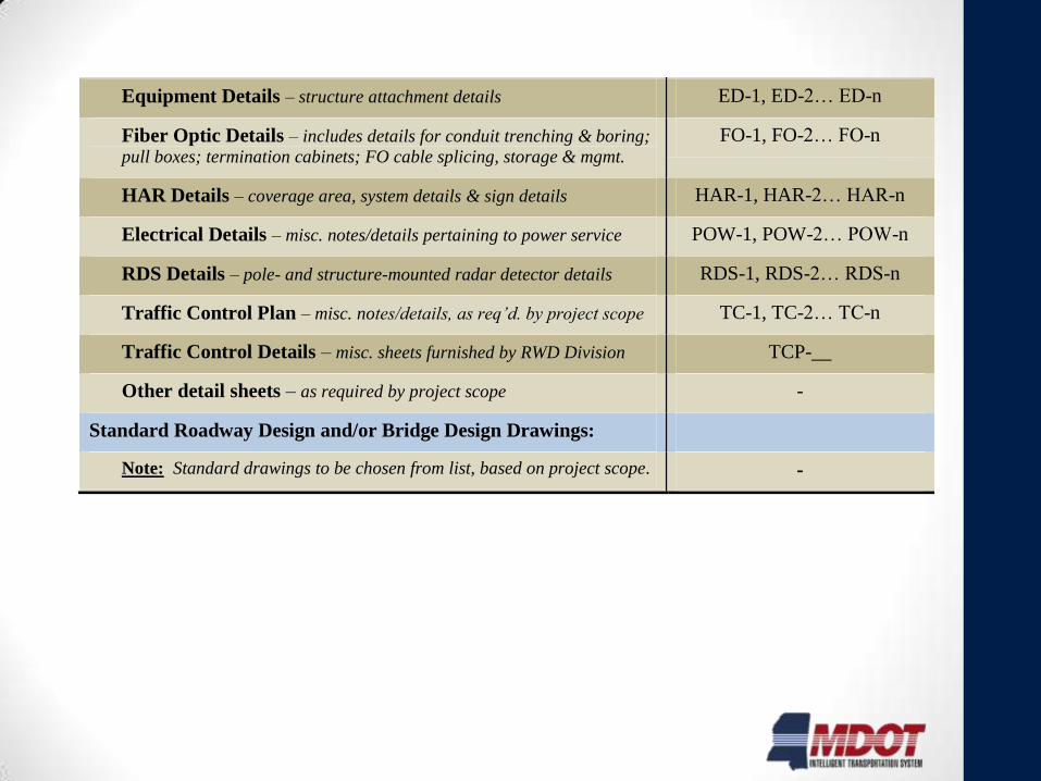
Equipment Details – structure attachment details ED-1, ED-2… ED-n
Fiber Optic Details – includes details for conduit trenching & boring;
pull boxes; termination cabinets; FO cable splicing, storage & mgmt. FO-1, FO-2… FO-n
HAR Details – coverage area, system details & sign details HAR-1, HAR-2… HAR-n
Electrical Details – misc. notes/details pertaining to power service POW-1, POW-2… POW-n
RDS Details – pole- and structure-mounted radar detector details RDS-1, RDS-2… RDS-n
Traffic Control Plan – misc. notes/details, as req’d. by project scope TC-1, TC-2… TC-n
Traffic Control Details – misc. sheets furnished by RWD Division TCP-__
Other detail sheets – as required by project scope -
Standard Roadway Design and/or Bridge Design Drawings:
Note: Standard drawings to be chosen from list, based on project scope. -
SHEET DESCRIPTION WORKING NUMBER(S)
Title Sheet -
Detailed Index & ITS Legend DI-1
General Notes GN-1
Summary of Quantities – recap of all project quantities SQ-1, SQ-2… SQ-n
Estimated Quantities – sheet-by-sheet & other special qty. tabulations EQ-1, EQ-2… EQ-n
Project Location Plan – serves as key map for ITS Plan Sheets LP-1
ITS Plan Sheets:
Mainline – identify route/street name and station limits ITS-1, ITS-2… ITS-n
Additional route/street names and station limits, as required ITS-p, ITS-q… ITS-z
Special Design Sheets:
Aerial-Supported Conduit – structure attachment details ASC-1, ASC-2… ASC-n
Cabinet Details – details for Type A, B or C cabinets, where req’d. CAB-1, CAB-2… CAB-n
CCTV Details – details for pole- or structure-mounted CCTV cameras CCTV-1, CCTV-2… CCTV-n
DMS Details – includes elevation- and plan-view clearance diagrams
and other details for each overhead and roadside DMS installation DMS-1, DMS-2… DMS-n
Erosion Control Plan – misc. notes/details, as req’d. by project scope EC-1, EC-2… EC-n
Equipment Details – structure attachment details ED-1, ED-2… ED-n
Fiber Optic Details – includes details for conduit trenching & boring;
pull boxes; termination cabinets; FO cable splicing, storage & mgmt. FO-1, FO-2… FO-n
HAR Details – coverage area, system details & sign details HAR-1, HAR-2… HAR-n
Electrical Details – misc. notes/details pertaining to power service POW-1, POW-2… POW-n
RDS Details – pole- and structure-mounted radar detector details RDS-1, RDS-2… RDS-n
Traffic Control Plan – misc. notes/details, as req’d. by project scope TC-1, TC-2… TC-n
Traffic Control Details – misc. sheets furnished by RWD Division TCP-__
Other detail sheets – as required by project scope -
Standard Roadway Design and/or Bridge Design Drawings:
Note: Standard drawings to be chosen from list, based on project scope. -

Appendices
• A – Plans Checklist – What is needed for 50% - 100% Submittals
• B – Model Sheets
• C – Typical Label Formats
• D – Special Provisions (latest at time of design manual published version)
• E – Example Notice to Bidder Documents