measurement, 4-1 flowmeters do rotameter tubes work? correct installation of rotameters. advantages...
TRANSCRIPT

© Festo Didactic 86005-00 65
Learn the basics of differential pressure flowmeters via the use of a Venturi tube and learn how to safely connect (and disconnect) a differential pressure flowmeter to (and from) a running process using a three-valve manifold.
The Discussion of this exercise covers the following points:
RotametersHow do rotameter tubes work? Correct installation of rotameters. Advantages and limitations of rotameters.
Venturi tubesHow do Venturi tubes work? Permanent pressure loss. Correct installation of Venturi tubes. Advantages and limitations of Venturi tubes.
Three-valve manifoldHow to connect a differential-pressure transmitter to a flowmeter. How to disconnect a differential-pressure transmitter from a flowmeter.
Rotameters
Rotameters belong to the variable-area flowmeters category. That is, flowmeters that allow the fluid to flow through a cross-sectional area that varies with the flow rate. A typical rotameter consists of a tapered metering tube. Rotameters are usually made of glass, although some are made of stainless steel to resist higher pressure and temperature. Inside the rotameter tube, there is a metering float (also called a bob) usually made of a metal such as brass or stainless steel. When liquid flows in the rotameter, the height of the float varies with the flow rate. Glass rotameters provide a direct reading of the flow rate by allowing the user to look at the float through the glass tube. Metal rotameters are equipped with a pointer indicator for reading measurement values.
How do rotameter tubes work?
Rotameters take advantage of the weight of the float for the measurement of the flow rate of fluids. Therefore, the only way to install a rotameter is vertically, so that the float rests at the bottom of the tube when no fluid flows through the meter. When a fluid flows from the bottom to the top of the rotameter, it pushes the metering float until the weight of the metering float, the buoyancy, and the drag force are at equilibrium. The higher the flow rate, the higher the level of the float.
An annular passage between the float and the wall of the tube allows fluid to pass. The tapered shape of the tube allows this annular cross-sectional area to increase as the fluid pushes the float upward. This keeps the pressure loss across the rotameter nearly constant as the flow rate increases.
Flowmeters
Exercise 4-1
EXERCISE OBJECTIVE
DISCUSSION OUTLINE
DISCUSSION

Ex. 4-1 – Flowmeters Discussion
66 © Festo Didactic 86005-00
Manufacturers design the rotameter tube and the float for a specific fluid. The weight and shape of the float is important in the design of the rotameter. The manufacturer must adapt the design of the instrument to the density, specific gravity, and dynamic viscosity of a specific fluid (for example water). Floats come in various shapes and, depending on the float shape, the user reads the flow rate either when the top of the float or when the reading mark on the float is in line with the tube scale. The float is either free to move sideways as well as vertically in the rotameter tube or a rod may restrict its motion and allow it to slide only up and down. If the float is free to move, the manufacturer adds some special grooves to its design, so that it rotates at a frequency of about 1 Hz to improve the stability of the float. It is from the rotation of the float that the rotameter takes its name. Figure 4-8 shows a typical rotameter.
Figure 4-8. Typical rotameter.
Correct installation of rotameters
Because of their design, you must always install rotameters vertically, with the small end of the tapered tube at the bottom. The bottom of the rotameter is the inlet. The fluid must flow from the inlet to the top of the rotameter so that the fluid pushes the float upward. Always avoid installing a valve that may create a sudden burst of pressure in the rotameter and cause the float to strike the float stop. Glass or acrylic rotameters are sensitive to vibrations and heavy loads. On industrial installations, always install rotameters using the appropriate supports. Rotameters are also limited in pressure and temperature. Make sure your process cannot exceed the physical limitations of your rotameter.
Advantages and limitations of rotameters
Rotameters are easy to use, they cause a small constant pressure loss, and they do not require any power supply to operate. Their construction is robust and simple and they offer high reliability. The accuracy of most rotameters is usually within 2% of their full scale. If the manufacturer has not indicated the accuracy on the instrument, you can assume that it is plus or minus half of the smallest division. Rotameters are inexpensive when compared to other types of flowmeters and they require almost no maintenance over their relatively long operating lives.

Ex. 4-1 – Flowmeters Discussion
© Festo Didactic 86005-00 67
On the other hand, rotameters can only operate in a vertical position since their working principle relies on gravity. The design and the graduation of a rotameter are always specific to a fluid, a range of temperature, and a range of pressure. If the temperature or the pressure of the process fluid changes, its density and viscosity also change and large measurement errors may occur. Another disadvantage of rotameters is that most of them provide only a visual indication of the volumetric flow rate. Therefore, it is impossible to use a rotameter for closed-loop control of the flow rate, unless a magnetic coupling is used to sense and transmit the position of the float to the controller.
Venturi tubes
A Venturi tube is a differential pressure flowmeter; it is the oldest and the most accurate type of differential pressure flowmeter. Clemens Herschel (1842-1930) designed the first Venturi tube in 1887. Herschel based his design on principles derived from the Bernoulli equation. Venturi tubes sticking to this first design are sometimes referred to as classic Venturi tubes or Herschel Venturi tubes. The design of Venturi tubes has been fine-tuned over the years to reduce the cost and shorten the laying length. The short form Venturi tube was first introduced in the 1950’s. The Venturi tube provided with your system is a short form Venturi with a low permanent pressure-loss design. Figure 4-9 shows a Venturi tube similar to the one provided with the Instrumentation and Process Control Training System. It consists of a cylindrical inlet section, a convergent section, a throat, a divergent section, and a cylindrical outlet section. The ends of the Venturi have National Pipe Threads (NPT) to avoid leakage where the Venturi connects to the PVC pipes.
Figure 4-9. Typical Venturi tube design.
Low-pressure port
High-pressure port
Low-pressure port
Divergent section
NPT
Outlet
Throat Convergentsection
NPTInlet
Flow
Ex. 4-1 – Flowmeters Discussion
68 © Festo Didactic 86005-00
How do Venturi tubes work?
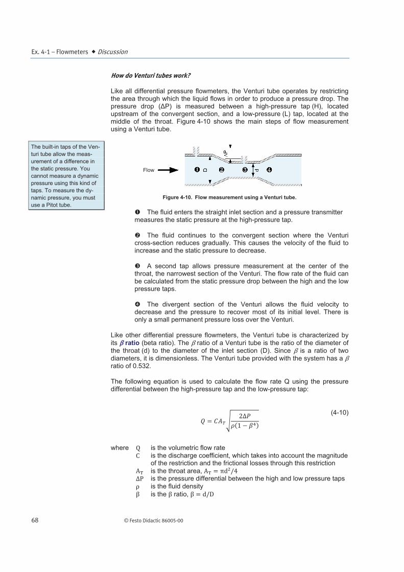
Like all differential pressure flowmeters, the Venturi tube operates by restricting the area through which the liquid flows in order to produce a pressure drop. The pressure drop ( P) is measured between a high-pressure tap (H), located upstream of the convergent section, and a low-pressure (L) tap, located at the middle of the throat. Figure 4-10 shows the main steps of flow measurement using a Venturi tube.
Figure 4-10. Flow measurement using a Venturi tube.
The fluid enters the straight inlet section and a pressure transmitter measures the static pressure at the high-pressure tap.
The fluid continues to the convergent section where the Venturi cross-section reduces gradually. This causes the velocity of the fluid to increase and the static pressure to decrease.
A second tap allows pressure measurement at the center of the throat, the narrowest section of the Venturi. The flow rate of the fluid can be calculated from the static pressure drop between the high and the low pressure taps.
The divergent section of the Venturi allows the fluid velocity to decrease and the pressure to recover most of its initial level. There is only a small permanent pressure loss over the Venturi.
Like other differential pressure flowmeters, the Venturi tube is characterized by
its ratio (beta ratio). The ratio of a Venturi tube is the ratio of the diameter of the throat (d) to the diameter of the inlet section (D). Since is a ratio of two diameters, it is dimensionless. The Venturi tube provided with the system has a ratio of 0.532.
The following equation is used to calculate the flow rate Q using the pressure differential between the high-pressure tap and the low-pressure tap:
(4-10)
where is the volumetric flow rate
is the discharge coefficient, which takes into account the magnitude of the restriction and the frictional losses through this restriction
is the throat area, is the pressure differential between the high and low pressure taps
is the fluid density is the ratio,
The built-in taps of the Ven-
turi tube allow the meas-
urement of a difference in
the static pressure. You
cannot measure a dynamic
pressure using this kind of
taps. To measure the dy-
namic pressure, you must
use a Pitot tube.
Flow

Ex. 4-1 – Flowmeters Discussion
© Festo Didactic 86005-00 69
Permanent pressure loss
Because Venturi tubes have no sharp edges or corners, unlike orifice plates, they allow the liquid to flow smoothly, which minimizes friction. However, friction cannot be eliminated altogether, so there is always a permanent pressure loss across the Venturi tube. The permanent pressure loss of a Venturi tube is typically between 10% and 25% of the pressure drop it produces. The permanent pressure loss of differential pressure flowmeters, such as Venturi tubes, is usually defined as the ratio of the pressure differential between the inlet and outlet of the instrument and the differential pressure between the high pressure and low pressure ports of the flowmeter:
(4-11)
where is the percentage of permanent pressure loss of the differential pressure flowmeter
is the pressure differential between the inlet and outlet of the flowmeter
is the pressure differential between the high pressure and low pressure ports of the flowmeter
The permanent pressure loss of a Venturi tube depends both on its ratio and on the angle of divergence of its outlet section. Some Venturis have a low-pressure loss design, which minimizes the pressure loss. When it comes to the reduction of the permanent pressure loss of a Venturi, the manufacturer has two main options:
• The permanent pressure loss in a Venturi is inversely proportional to the ratio.
The manufacturer can increase the ratio to decrease the permanent pressure loss. To increase the ratio, the manufacturer can either increase the diameter of the throat or reduce the diameter of the inlet section.
• The permanent pressure loss in a Venturi is directly proportional to the angle of divergence of the outlet section. The manufacturer can design a Venturi with a small angle at the outlet cone in order to reduce the permanent pressure loss. However, reducing the angle of the outlet cone increases the length of the outlet section.
The Venturi tube provided with the system is a good compromise between the
two solutions. It has a high ratio, which reduces the pressure loss. On the other hand, it has a large outlet-cone angle compared to a Herschel Venturi, which reduces its laying length but slightly increases the permanent pressure loss.

Ex. 4-1 – Flowmeters Discussion
70 © Festo Didactic 86005-00
Correct installation of Venturi tubes
As for most flowmeters, a minimum length of straight pipe run must be present before and after a Venturi tube. This minimizes the effect of turbulences on the measurement. For a Venturi tube, the worst-case scenario is an installation where two elbows in different planes are present before the tube. This type of setup may require a straight pipe run of at least 20 times the diameter of the pipe before the Venturi tube. In such a case, a straight pipe run of 4 times the diameter of the pipe must be located after the flowmeter.
Venturi tubes also require a fully developed turbulent flow to produce accurate results. If an application requires a laminar or transitional flow to be measured, you will have to rely on a more sophisticated type of instrument such as a magnetic flowmeter or a mass flowmeter to measure the flow rate.
The differential-pressure transmitter used to measure the pressure differential between the ports of the Venturi tube must be located as close as possible to the flowmeter. For a horizontal installation to measure a gas flow, the pressure ports of the Venturi should be on the top (Figure 4-11). For a horizontal installation to measure a liquid flow, the Venturi tube should be positioned so that its pressure ports are on the side (Figure 4-12). This prevents air from entering in the impulse lines and dirt from blocking the pressure ports.
Advantages and limitations of Venturi tubes
Venturi tubes are highly accurate; they recover most of the pressure drop they produce, and they are less susceptible to erosion than orifice plates because of their smoother contour. Moreover, Venturi tubes can generally be used in slurry processes, because their gradually sloping shape allows solids to flow through.
However, Venturi tubes are relatively expensive and they require the use of a differential-pressure transmitter, which contributes to the total cost of the flow measurement setup. They tend to be voluminous, and they may be difficult to install. Venturi tubes also require a certain length of straight pipe both upstream and downstream to ensure a flow that is undisturbed by fittings, valves, or other equipment. However, the required pipe lengths are shorter than those required for orifice plates.
Three-valve manifold
Differential pressure flowmeters such as Venturi tubes or orifice plates require a differential-pressure transmitter for flow measurement. In most industrial applications, the differential-pressure transmitter must be connected to the flowmeter without stopping the process. If the pipe pressure is high, the transmitter may be damaged if it is not connected correctly.
Because of their design, most differential-pressure transmitters cannot withstand high pressure being applied only on one side of their sensing diaphragm or capsule. Applying too much pressure on the sensing cell of the transmitter is called overranging. To avoid overranging the sensing cell, an equal pressure must be applied on both sides of the transmitter when connecting it to the flowmeter. A three-valve manifold is a simple device used for this purpose. Using a three-valve manifold isolates the differential-pressure transmitter from the process, avoids overranging, and allows the zero of the transmitter to be set.
Figure 4-11. Pressure port position for air-flow measurement.
Figure 4-12. Pressure port position for liquid-flow measurement

Ex. 4-1 – Flowmeters Discussion
© Festo Didactic 86005-00 71
Figure 4-13 shows how a three-valve manifold is connected to a differential-pressure transmitter.
Figure 4-13. Three-valve manifold connected to a differential-pressure transmitter.
How to connect a differential-pressure transmitter to a flowmeter
Table 4-1 below lists the operational sequence for connecting a differential-pressure transmitter to a differential pressure flowmeter via a three-valve manifold. This sequence details how to install and set the zero of the transmitter while the process is running.
Table 4-1. Using a three-valve manifold to connect a differential-pressure transmitter to a process.
1 Make sure the valves of the three-valve manifold are closed. Connect the differential-pressure transmitter in parallel with the equalizing valve as shown in the figure on the right.
2 Open the equalizing valve to allow pressure to equalize on both sides of the transmitter. At this point, the differential pressure read by the transmitter is zero. Set the zero of the differential transmitter.
3
Slowly open the high-pressure block valve of the three-valve manifold. Since the manifold applies the same pressure on both sides of the transmitter, there is no risk of overranging the sensing cell. Make sure there are no leaks in the connections to the transmitter.
To the low- pressure port
of the flow meter
To the high- pressure port
of the flow meter
Low-pressureblock valve
High-pressure block valve
Three-valvemanifold
Equalizingvalve
Ex. 4-1 – Flowmeters Discussion
72 © Festo Didactic 86005-00
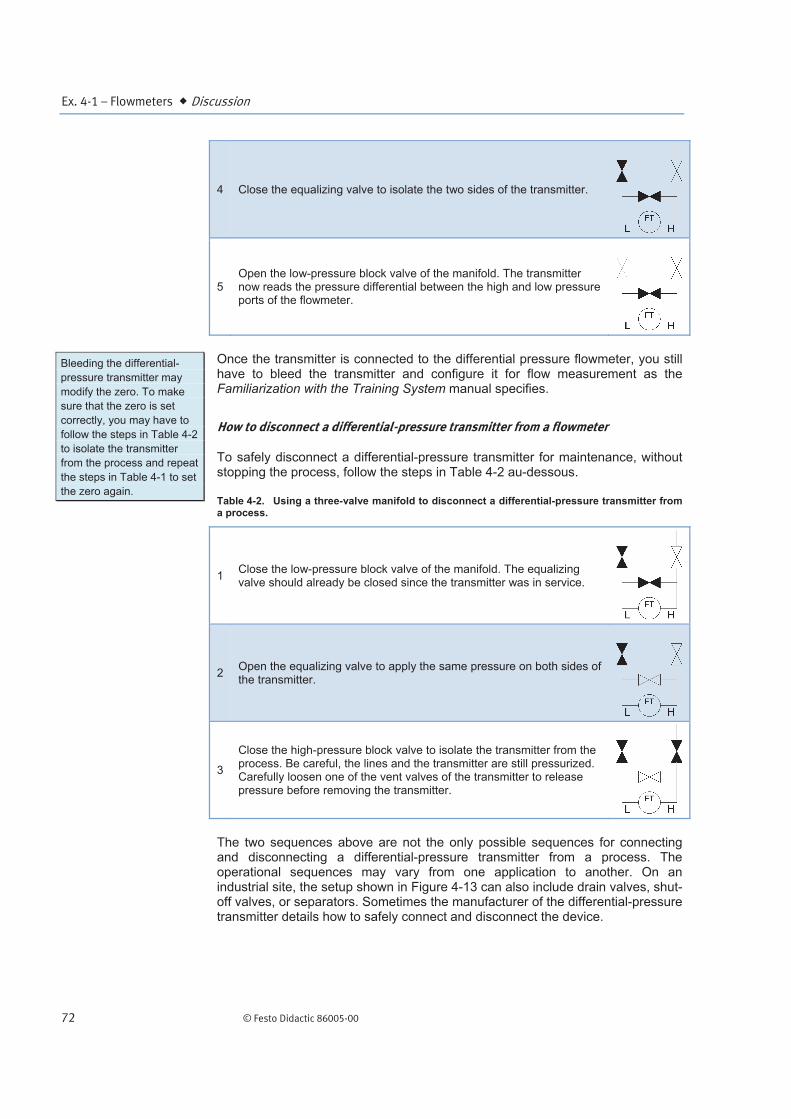
4 Close the equalizing valve to isolate the two sides of the transmitter.
5 Open the low-pressure block valve of the manifold. The transmitter now reads the pressure differential between the high and low pressure ports of the flowmeter.
Once the transmitter is connected to the differential pressure flowmeter, you still have to bleed the transmitter and configure it for flow measurement as the Familiarization with the Training System manual specifies.
How to disconnect a differential-pressure transmitter from a flowmeter
To safely disconnect a differential-pressure transmitter for maintenance, without stopping the process, follow the steps in Table 4-2 au-dessous.
Table 4-2. Using a three-valve manifold to disconnect a differential-pressure transmitter from a process.
1 Close the low-pressure block valve of the manifold. The equalizing valve should already be closed since the transmitter was in service.
2 Open the equalizing valve to apply the same pressure on both sides of the transmitter.
3
Close the high-pressure block valve to isolate the transmitter from the process. Be careful, the lines and the transmitter are still pressurized. Carefully loosen one of the vent valves of the transmitter to release pressure before removing the transmitter.
The two sequences above are not the only possible sequences for connecting and disconnecting a differential-pressure transmitter from a process. The operational sequences may vary from one application to another. On an industrial site, the setup shown in Figure 4-13 can also include drain valves, shut-off valves, or separators. Sometimes the manufacturer of the differential-pressure transmitter details how to safely connect and disconnect the device.
Bleeding the differential-
pressure transmitter may
modify the zero. To make
sure that the zero is set
correctly, you may have to
follow the steps in Table 4-2
to isolate the transmitter
from the process and repeat
the steps in Table 4-1 to set
the zero again.
Ex. 4-1 – Flowmeters Procedure Outline
© Festo Didactic 86005-00 73
The Procedure is divided into the following sections:
Setup and connections
Permanent pressure loss across the Venturi tube
Pressure differential between the high and low pressure taps of the Venturi tube
Measuring flow rates using a Venturi tube
Setup and connections
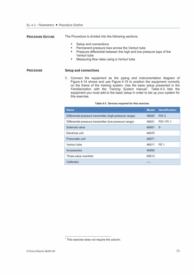
1. Connect the equipment as the piping and instrumentation diagram of Figure 4-14 shows and use Figure 4-15 to position the equipment correctly on the frame of the training system. Use the basic setup presented in the Familiarization with the Training System manual
1. Table 4-3 lists the
equipment you must add to the basic setup in order to set up your system for this exercise.
Table 4-3. Devices required for this exercise.
Name Model Identification
Differential-pressure transmitter (high-pressure range) 46920 PDI 2
Differential-pressure transmitter (low-pressure range) 46921 PDI 1/FI 1
Solenoid valve 46951 S
Electrical unit 46970
Pneumatic unit 46971
Venturi tube 46911 FE 1
Accessories 46993
Three-valve manifold 85813
Calibrator ----
1 This exercise does not require the column.
PROCEDURE OUTLINE
PROCEDURE

Ex. 4-1 – Flowmeters Procedure
74 © Festo Didactic 86005-00
Figure 4-14. P&ID.
Calibrator (4-20 mA)
24 V from theElectrical Unit

Ex. 4-1 – Flowmeters Procedure
© Festo Didactic 86005-00 75
Figure 4-15. Setup.
2. In this exercise, you will control the flow rate in the system using a hand valve instead of the control valve. Therefore, there is no need to connect the control valve to the pneumatic unit since it is a fail-open valve. However, if you want to control the flow rate using the control valve, connect your control valve as required and connect the pneumatic unit to a dry-air source with an output pressure of at least 700 kPa (100 psi).
3. Wire the emergency push-button so that you can cut power in case of an emergency.
4. Do not power up the instrumentation workstation before your instructor has validated your setup.
5. Connect the solenoid valve so that a voltage of 24 V dc actuates the solenoid when you turn the power on.

Ex. 4-1 – Flowmeters Procedure
76 © Festo Didactic 86005-00
6. Be sure to install both differential-pressure transmitters under the Venturi tube.
7. Before proceeding further, complete the following checklist to make sure you have set up the system properly. The points on this checklist are crucial elements for the proper completion of this exercise. This checklist is not exhaustive, be sure to follow the instructions in the Familiarization with the Training System manual as well.
f
The solenoid valve is wired so that the valve opens when the system is
turned on.
The hand valves are in the positions shown in the P&ID.
The control valve is fully open.
The current to pressure converter is properly configured.
The pneumatic connections are correct.
The differential-pressure transmitters are installed correctly.
8. Ask your instructor to check and approve your setup.
9. Power up the electrical unit.
10. Test your system for leaks. Use the drive to make the pump run at low speed in order to produce a small flow rate. Gradually increase the flow rate, up to 50% of the maximum flow rate the pumping unit can deliver. Repair all leaks.
11. Fill the pipes completely with water and bleed both differential-pressure transmitters.
12. Configure the differential-pressure transmitters so that they give pressure readings in the desired units.
13. Adjust the zero of both transmitters to read a pressure of 0 kPa (0 psi) when there is no flow. You do not have to use the three-valve manifold now. You will have time to familiarize yourself with the three-valve manifold in the second part of this exercise.
Permanent pressure loss across the Venturi tube
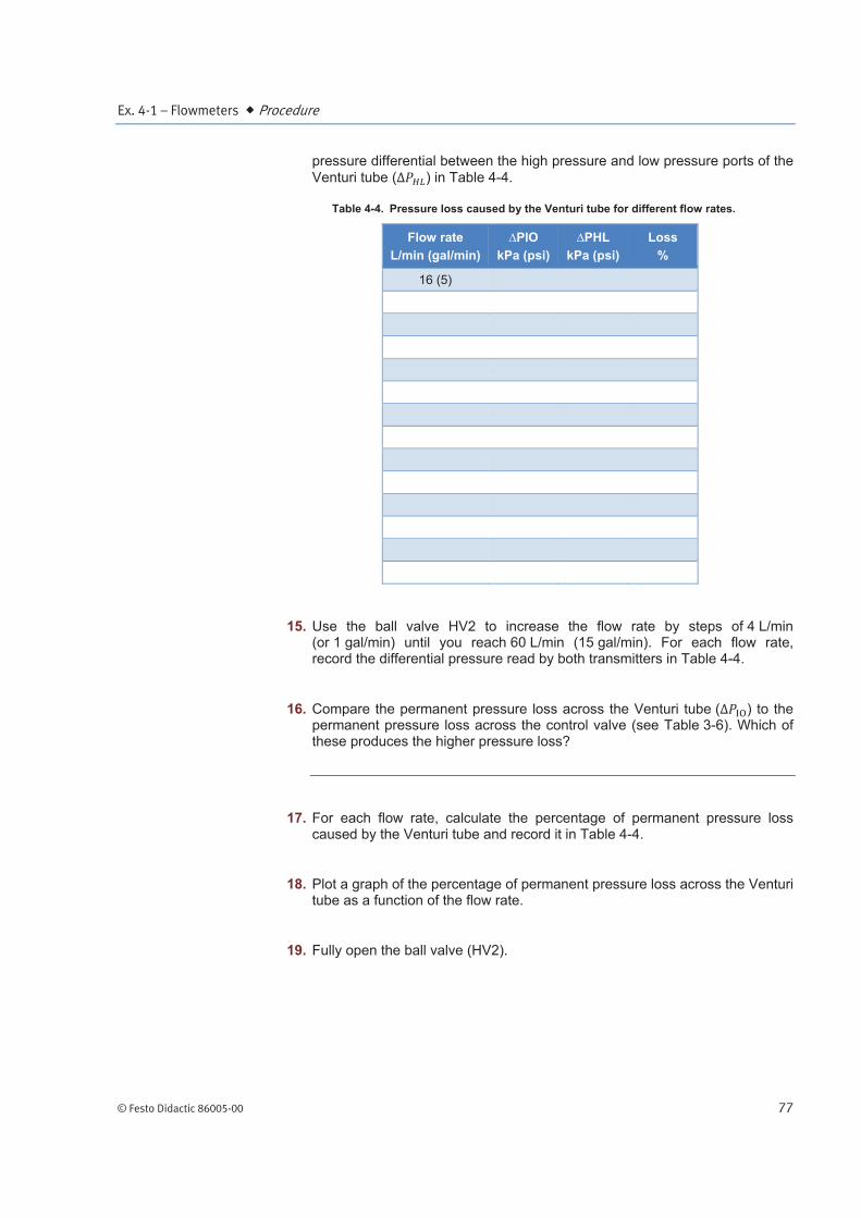
14. Set the pump to its maximum speed and use the ball valve HV2 under the rotameter to adjust the flow rate to 16 L/min (5 gal/min). Record the pressure
differential between the inlet and outlet of the Venturi tube ( ) and the
Ex. 4-1 – Flowmeters Procedure
© Festo Didactic 86005-00 77
pressure differential between the high pressure and low pressure ports of the
Venturi tube ( ) in Table 4-4.
Table 4-4. Pressure loss caused by the Venturi tube for different flow rates.
Flow rate
L/min (gal/min)
PIO
kPa (psi)
PHL
kPa (psi)
Loss
%
16 (5)
15. Use the ball valve HV2 to increase the flow rate by steps of 4 L/min (or 1 gal/min) until you reach 60 L/min (15 gal/min). For each flow rate, record the differential pressure read by both transmitters in Table 4-4.
16. Compare the permanent pressure loss across the Venturi tube ( ) to the permanent pressure loss across the control valve (see Table 3-6). Which of these produces the higher pressure loss?
17. For each flow rate, calculate the percentage of permanent pressure loss caused by the Venturi tube and record it in Table 4-4.
18. Plot a graph of the percentage of permanent pressure loss across the Venturi tube as a function of the flow rate.
19. Fully open the ball valve (HV2).

Ex. 4-1 – Flowmeters Procedure
78 © Festo Didactic 86005-00
Pressure differential between the high and low pressure taps of the Venturi tube
20. Equation (4-10) shows that the flow rate, , is proportional to the square root
of pressure drop across the pressure taps of the Venturi tube, . This exercise shows you how to configure the differential-pressure transmitter to measure a flow rate using a Venturi tube. However, before measuring a flow rate using the Venturi tube, you will measure the pressure drop across the Venturi tube for different flow rates in order to check the relationship given in Equation (4-10).
21. Make sure the pump is still running and use the ball valve HV2 to adjust the flow rate to 20 L/min (5 gal/min).
22. Use the three-valve manifold to set the zero of the differential-pressure transmitter. Refer to the Three-Valve Manifold section of the Familiarization with the Training System manual if required.
23. Figure 4-16 and Figure 4-17 show how you should connect your system to measure a flow using the Venturi tube.
Figure 4-16. P&ID.
Calibrator (4-20 mA)
24 V from theElectrical Unit

Ex. 4-1 – Flowmeters Procedure
© Festo Didactic 86005-00 79
Figure 4-17. Setup.
24. Use the ball valve HV2 to adjust the flow rate to 4 L/min (1 gal/min).

Ex. 4-1 – Flowmeters Procedure
80 © Festo Didactic 86005-00
25. On the differential-pressure transmitter, read the pressure differential across the Venturi tube taps for this flow. Make sure the flow rate and the pressure are stable before recording the pressure drop value in Table 4-5.
Table 4-5. Pressure differential across the Venturi tube taps for different flow rates.
Flow rate
L/min (gal/min)
P
kPa (psi)
( P)½
kPa½ (psi½)
4 (1)
26. Use the ball valve HV2 to increase the flow rate by steps of 2 L/min (or 1 gal/min) until you reach 40 L/min (19 gal/min). For each flow rate, record the pressure drop across the pressure taps of the Venturi tube in Table 4-5.
27. Plot a graph of the pressure drop across the control valve as a function of the flow rate using the data in Table 4-5.
28. Calculate the square root of the pressure drop for each flow rate and fill in the appropriate column of Table 4-5 with the results.
29. Plot a graph of the square root of the pressure drop as a function of the flow rate using the data in Table 4-5.

Ex. 4-1 – Flowmeters Procedure
© Festo Didactic 86005-00 81
30. Referring to this graph, does the relationship between the flow rate and the square root of the pressure drop look linear?
Measuring flow rates using a Venturi tube
31. Configure the differential-pressure transmitter for flow rate measurement. Refer to the Familiarization with the Training System manual for details.
32. Use the ball valve HV2 to adjust the flow rate so that the rotameter reading is 4 L/min (1 gal/min).
33. In Table 4-6, record the flow rate reading of the differential-pressure transmitter.
Table 4-6. Differential-pressure transmitter and rotameter flow rate reading.
Flow rate
(Rotameter)
L/min (gal/min)
Flow rate
(Venturi tube)
L/min (gal/min)
4 (1)
34. Use the ball valve HV2 to increase the flow rate (as read on the rotameter) by steps of 4 L/min (or 1 gal/min) until you reach 40 L/min (10 gal/min). For

Ex. 4-1 – Flowmeters Conclusion
82 © Festo Didactic 86005-00
each flow rate, record the flow rate reading of the differential-pressure transmitter in Table 4-6.
35. Compare the flow rate reading of the differential-transmitter to the flow rate reading of the rotameter.
36. Use the main switch to cut the power to the Instrumentation and Process Control Training System.
In this exercise, you measured the percentage of permanent pressure loss caused by a Venturi tube. You compared the pressure loss caused by the Venturi tube to the pressure loss caused by a control valve. You have confirmed that the flow rate is proportional to the square root of the pressure drop between the high and low pressure port of a Venturi tube. You also learned how to properly connect a differential-pressure transmitter to a system while the process is running and how to use this same transmitter to measure the flow rate directly using a Venturi tube.
1. Why must you install rotameters vertically?
2. Which characteristics of a fluid have an influence on the design of a rotameter?
3. To which class of flowmeters do the Venturi tubes belong?
4. Name three advantages of Venturi tubes.
5. Name one function of a three-valve manifold.
CONCLUSION
REVIEW QUESTIONS