measurement analysis of electroma gnetic disturbance of
TRANSCRIPT

Measurement Analysis of Electromagnetic Disturbance of the Secondary Sides of TA&TV in Local Control Cubicle of Dead Tank and Live Tank
SF6 Circuit-breaker
Qiang Xu 1, a,Jianfei Ji 1, b, Jiayu Huang 2,c 1Jiangsu Provincial Power Company, Jiangsu, Nanjing, 211103
2Southeast University, Jiangsu, Nanjing, 210096 [email protected], [email protected], [email protected]
Keywords:dead tank type, live tank type, electromagnetic disturbance, secondary circuit, circuit-breaker Abstract.The secondary circuit in substations is in a strong electromagnetic environment, and intelligent devices may be affected by electromagnetic disturbance signals. Meanwhile, with the local installation of intelligent devices, the electromagnetic disturbance of its working environment may be further strengthened. In recent years, there have been many accidents about abnormal operation of intelligent devices caused by the disturbance of secondary circuit in substations by circuit breaker and isolation switch. Therefore, it is with great significance to study the electromagnetic compatibility issue of the secondary circuit in substations. This paper has tested and recorded the electromagnetic disturbance in TA&TV secondary side of the local cabinet in the 500kV substation caused by the dead tank and live tank type circuit-breaker. The time domain and frequency domain of the measurement results are analyzed, the result of which indicates that the amplitudes of electromagnetic transient signals caused by the dead tank type breaker operation are all greater than that caused by the live tank type of breaker operation. However, the frequency of disturbance signals caused by dead tank circuit breaker is mostly concentrated in the KHz level, but that caused by the live tank type of breaker is distributed in the high-frequency section of MHz. Finally, some suggestions are proposed to improve the electromagnetic compatibility performance of the on-site secondary smart devices.
Introduction
In the recent design and construction of the 500kV substations in our country, the secondary equipment of protection and control is usually put from the relay protection room to the switching field, and centrally located in the control cabinet. In the substation, the primary sideof TA is usually installed on the short bus bar between the circuit breaker and the isolating switch, and the secondary cable gets to the control cabinet by the plastic coated metal hose, hub groove and cable trench. Therefore, the terminal voltage of the control cabinet is the main indicators to measure the disturbance of the secondary system and the important parameters determining the secondary equipment electromagnetic compatibility immunity requirement. In recent years, many foreign and domestic scholars have done a lot of work on the electromagnetic disturbance caused by the switch operation in substations.
The literature [1] carries out the simulation analysis on the electromagnetic disturbance caused by the thyristor switching in the ±800kV ultra high voltage converter.The first system electromagnetic field in the ultra high voltage substation of Romania national electric power company is measured in the literature [2,3].The transient electromagnetic disturbance caused by low resistance in the 500kV called Tianyi substation is recorded in the paper [4], and the results show that the transient electromagnetic disturbance will not interfere the normal operation of the secondary equipment in the nearby main control building and the relay room.The transient electric field caused by separating and closing the no-load bus and short term of the isolating switch, closing lines of circuit breaker and using no-load transformer in two 500kV substations in China which is being debugged is measured in the test [5]. Some important characteristics of the transient electric field are obtained by analyzing the measured data. In the literature [6], the electromagnetic
2nd International Forum on Electrical Engineering and Automation (IFEEA 2015)
© 2016. The authors - Published by Atlantis Press 151

interference caused by the isolation switch operation in the 500kV substation and the impact of the secondary circuit and protection from that are tested. Some important characteristics of electromagnetic interference are obtained by analyzing the measured data. The paper [7] introduces a spherical probe for three dimensional electric field measurement and uses it to measure the power frequency electric field in a 220kV substation and the transient electric field caused by the switch operation. Through the analysis of the experimental data, some protective measures are proposed for the transient electromagnetic interference.The paper 8] discusses the measurement results of the secondary circuit electromagnetic disturbance caused by the isolating switch operation in different 500kV communication systems. The disturbance time and frequency characteristics are obtained by analyzing the time and frequency domain characteristics of the disturbance signal.The paper [9] establishes the 345kV GIS combination electric model by the software called EMTP/ATP and analyzes the overvoltage caused by the switch operation.The harm to the secondary and electronic equipment caused by the transient electromagnetic field generated from the isolating switch operation in the substation is discussed in the paper [10], and the characteristics that the transient electromagnetic field duration is short, the amplitude is great and the high frequency components are a lot are summarized.
The above literatures mainly do the research on the electromagnetic transient caused by the circuit breaker and isolating switch operation in the substation, without studying the condition that the electromagnetic disturbance caused by the switch operation in the substation transfers to the secondary side of TA in the local control cabinet.In order to examine the characteristics of the electromagnetic disturbance in TA secondary side of the local cabinet in substation, this paper has tested and recorded the electromagnetic disturbance in TA secondary side of the local cabinet in the 500kV substation caused by the dead tank and live tank type circuit-breaker. The time domain and frequency domain of the measurement results are analyzed, and the differences between the electromagnetic disturbancecaused by the dead tank and live tank type circuit-breaker are compared. Then some suggestions are proposed to improve the electromagnetic compatibility performance of the on-site secondary smart devices.
Dead Tank SF6 Circuit-breaker
Fig.1 shows that the 500kV substation uses the GIS combination electric equipment and 3/2 connection mode, and has 2 main transformers and 4 outlets. It uses the SF6circuit breaker which is HPL550B2 type without closing resistors made by the ABB and is dead tank type. Someday, the 500kV substation started debugging to put 5043 switch into 5907 line, and then the electromagnetic transient disturbance signal caused by switch operation was tested and measured.
In order to quantify the electromagnetic disturbance strength, the electromagnetic transient disturbance signal caused by switch operation was tested and measured. The electromagnetic transient disturbance signal detection system is composed of the oscilloscope, current probe and high voltage probe. The copper bar (grounding grid) is at the bottom of local control cabinet, and the recording point is put on the terminal box in local control cabinet. The secondary cable of TA and the secondary side cable of TV are led on the terminal line in local control cabinet.
152

II bus
5052
5051
5032
5033
5031
5043
5041
I bus
5622
5907
5042
5621
NO.1 main transformer
5022
5023
5917
NO.2 main transformer
Fig.1 Primary electric wiring diagram of the 500 kV GIS substation
In the recording oscilloscope, the sampling frequency is 1.25GSa/s, the bandwidth is 350MHz, and the storage depth is 4Mpts. The high voltage decay rod which is the HVP-15HF type from the PINTECH company is selected as the high voltage probe, and the specific parameters are as follows: the range of direct currentis 0-15kV,and the range of alternating current is 0-30kV; the signal to noise ratio is greater than 50dB when it is 1MHz; the division ratio is 1:1000; the input impedance is 100MΩ; the input capacitance is 3.0pF. The flexible current probewhich is the DK-1400 type from the PINTECH company is selected as the current probe, and the specific parameters are as follows: the input impedance is 100kΩ, the sensitivity is 5mv/1A. The differential probe is the DK-1400 type from the PINTECH company, and the bandwidth is 100MHz, input impedance is 4MΩ, input capacitance is 7.0pF, the attenuation ratio is 1:1000.
Fig.2 when the 5011 circuit breaker closed, the electromagnetic transient disturbance time-domain
waveform of every channel When the 5011 circuit breaker closed, the electromagnetic transient disturbance signal of the A
phase voltage, current and voltage channel of the secondary sides of TA is shown in Fig.2. It can be seen from the figure that the maximum peak to peak of the disturbance signal in the A phase voltage channel of the secondary sides of TA is about 2300V, and that of the disturbance signal in the A phase current of the secondary sides of TA is 700A. That of the disturbance signal in the A phase voltage of the secondary sides of TVis 2500V.
153
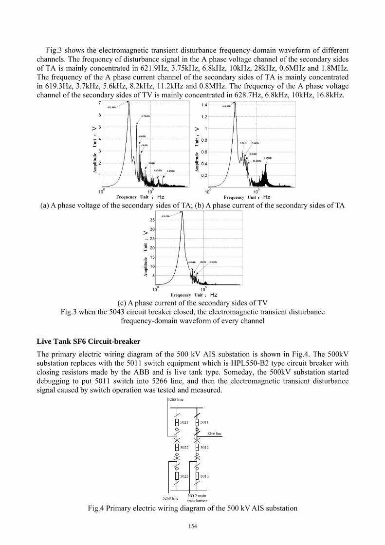
Fig.3 shows the electromagnetic transient disturbance frequency-domain waveform of different channels. The frequency of disturbance signal in the A phase voltage channel of the secondary sides of TA is mainly concentrated in 621.9Hz, 3.75kHz, 6.8kHz, 10kHz, 28kHz, 0.6MHz and 1.8MHz. The frequency of the A phase current channel of the secondary sides of TA is mainly concentrated in 619.3Hz, 3.7kHz, 5.6kHz, 8.2kHz, 11.2kHz and 0.8MHz. The frequency of the A phase voltage channel of the secondary sides of TV is mainly concentrated in 628.7Hz, 6.8kHz, 10kHz, 16.8kHz.
(a) A phase voltage of the secondary sides of TA; (b) A phase current of the secondary sides of TA
(c) A phase current of the secondary sides of TV
Fig.3 when the 5043 circuit breaker closed, the electromagnetic transient disturbance frequency-domain waveform of every channel
Live Tank SF6 Circuit-breaker
The primary electric wiring diagram of the 500 kV AIS substation is shown in Fig.4. The 500kV substation replaces with the 5011 switch equipment which is HPL550-B2 type circuit breaker with closing resistors made by the ABB and is live tank type. Someday, the 500kV substation started debugging to put 5011 switch into 5266 line, and then the electromagnetic transient disturbance signal caused by switch operation was tested and measured.
5265 line
5266 line
5022
5023
5021
5012
5013
5011
5268 lineNO.2 main transformer
Fig.4 Primary electric wiring diagram of the 500 kV AIS substation
154

When the 5011 circuit breaker closed, the electromagnetic transient disturbance signal of the A phase voltage, current and voltage channel of the secondary sides of TA is shown in Fig.5. It can be seen from the figure that the maximum peak to peak of the disturbance signal in the A phase voltage channel of the secondary sides of TA is about 1000V, and that of the disturbance signal in the A phase current of the secondary sides of TA is 300A. That of the disturbance signal in the A phase voltage of the secondary sides of TVis 1500V.
Fig.5 when the 5011 circuit breaker closed, the electromagnetic transient disturbance time-domain
waveform of every channel Fig.6 shows the electromagnetic transient disturbance frequency-domain waveform of different
channels. The frequency of disturbance signal in the A phase voltage channel of the secondary sides of TA is mainly concentrated in 10kHz, 30kHz, 90kHz, 200kHz, 400kHz, 1.33MHz, 33.8MHz, 156.2MHz and 312.5MHz. The frequency of the A phase current channel of the secondary sides of TA is mainly concentrated in 20kHz, 420kHz and 840kHz. The frequency of the A phase voltage channel of the secondary sides of TV is mainly concentrated in 30kHz, 80kHz, 220kHz, 290kHz, 400kHz, 600kHz, 9.6MHz, 83MHz and 195MHz.
(a) A phase voltage of the secondary sides of TA; (b) A phase current of the secondary sides of TA
155

(c) A phase current of the secondary sides of TV
Fig.6 when the 5011 circuit breaker closed, the electromagnetic transient disturbance frequency-domain waveform of every channel
When comparing the electromagnetic transient test data of dead tank and live tank SF6 circuit-breaker, it is not difficult to find that the amplitudes of the A phase voltage, current and voltage channel of the secondary sides of TA in electromagnetic transient signals caused by the dead tank type breaker operation are all greater than that caused by the live tank type of breaker operation. However, the frequency of disturbance signals caused by dead tank circuit breaker is mostly concentrated in the KHz level. But the frequency of disturbance signals caused by dead tank circuit breaker is much wider than that caused by the live tank type of breaker operation, and is distributed in the high-frequency section of MHz.
Conclusions
This paper has tested the electromagnetic disturbance in TA&TV secondary side of the local cabinet caused by the dead tank and live tank type circuit-breaker, and analyzed the measurement results. The results could be summarized as follows:
1. The amplitudes of electromagnetic transient signals caused by the dead tank type breaker operation are all greater than that caused by the live tank type of breaker operation. But the frequency of disturbance signals caused by dead tank circuit breaker is much wider than that caused by the live tank type of breaker operation, and is distributed in the high-frequency section of MHz.
2. At present, there aretwo kinds of frequency in domestic damped oscillatory wave test which are 1MHz and 100kHz.When the frequency is 100kHz, the repetition rate is at least 40 times/s, and when the frequency is 1MHz,that is at least 400 times/s. According to the experimental results, the disturbance signals are widely distributed in in the MHz level. The latest IEC61000-4 standard has added oscillation frequencies of 3MHz, 10MHz and 30MHz currently. Therefore, the corresponding oscillation frequency is proposed to be added in national standard.
3. Suggestions are made to improve the electromagnetic compatibility of the secondary intelligent component in local control cabinet.For example,the box is processed by the way of full conduction, and cancel the communication way through the back circuit board or strengthen the anti-interference performance of communication.It is recommended to improve the wiring way of ground wirein the terminal box, such as putting the copper ground row around the terminal boxto reduce the impedance between the equipment ground and the copper ground row.
Acknowledgements
This work was financially supported by the Natural Science Foundation of Jiangsu Province (BK20130099).
References
[1] Zhan-Qing Yu, Jin-Liang He, Rong Zeng. Simulation Analysis on Conducted EMD Caused by Valves in ±800 kV UHVDC Converter Station, IEEE Transactions on Electromagnetic
156

Compatibility, Vol.51, No.2, May., 2009.
[2] Gheorghe Visan, Ioan T. Pop and Calin Munteanu. Electric and Magnetic Field Distribution in Substations belonging to Transelectrica TSO, 2009 IEEE Bucharest Power Tech Conference, June., 2009.
[3] Calin Munteanu, Gheorghe Visan, Ioan T. Pop. Electric and Magnetic Field Distribution inside High and Very High Voltage Substations, The 20th Int. Zurich Symposium on EMC, Zurich, 2009.
[4] Haojun Yan, Jianming Wang, Xiaohua Yang. Transient Electromagnetic Disturbance caused by Low Resistance in the Tianyi 500kV Substation,High Voltage Engineering,Vol.34, No.1, Jan., 2008. In Chinese.
[5] Binxian Lu, Zezhong Lu, Chengrong Li.Measurement Study of the Transient Electric Field Caused By the Switch Operation in the 500Kv Station,Proceedings of the Chinese Society for Electrical Engineering,Vol.24, No.4, Apr., 2004. In Chinese.
[6] Yong Wang, He Chen.Electromagnetic Interference caused by the Isolation Switch Operation in the Substation and the Measurement of the Protection Impact,Relay,Vol.35, Dec., 2007. In Chinese.
[7] Zezhong Wang, Chengrong Li, Peng Li.Transient E-field Measurement in Substation Using Spherical Sensor,Journal of North China Electric Power University, Vol.29, No.3, July., 2002. In Chinese.
[8] Xiaojian Li, Yao Zhong, Ren Wang.Time and Frequency Domain Characteristics of the Electromagnetic Disturbance caused by the Isolating Switch Operation in 500kV Substation, Yunnan Electric Power, Vol.39, No.4, Aug., 2011.In Chinese.
[9] FENG-ZIH WU, LI-MING CHEN, CHIH-JU CHOU. Analysis of Switching Surge Characteristics Of 345KV GIS And Their Affections Assessments, Proceedings of the 2011 International Conference on Machine Learning and Cybernetics, Guilin, 10-13 July., 2011.14
[10] Qingquan Li.Transient Electromagnetic Field Caused by the Switch Operation in the Substation and the Protection of it, High Voltage Engineering, Vol.27, No.4, Aug., 2001.In Chinese.
157