mec 130 mechanisms - skillscommons
TRANSCRIPT

1
MEC 130 – Mechanisms
Types of Clutches
Before you learn about the different types of clutches, answer a quick question to check your
knowledge of what a clutch is.
Which of the following statements defines a clutch accurately?
1. A device used to engage or disengage power from a driving shaft to a driven shaft
2. A mechanical device that slows or stops a moving object by absorbing energy
3. A device that joins two or more objects mechanically to create non-permanent joints
4. A machine element that constrains relative motion to only the desired motion while
reducing friction and handling stress
Correct answer: 1
When engaged, a clutch provides for power transmission from one component to another,
especially from driving shaft to driven-shaft. The driven shaft may be stopped without
stopping the driving shaft. Also power is transferred, the clutch can disengage, and the
driven shaft can be stopped without stopping the driving.
In automobiles with manual transmissions, the power from the engine crankshaft flows to the
drive wheels through a clutch located between the engine and the gear box.
2
MEC 130 – Mechanisms
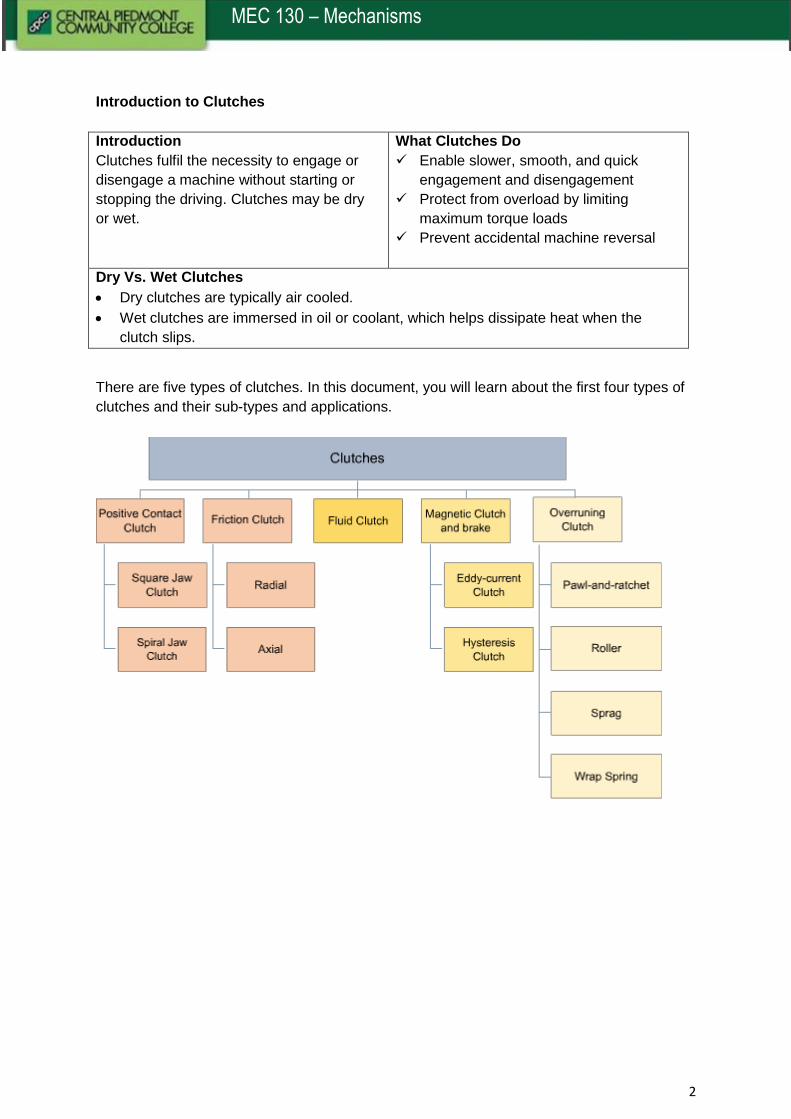
Introduction to Clutches
Introduction
Clutches fulfil the necessity to engage or
disengage a machine without starting or
stopping the driving. Clutches may be dry
or wet.
What Clutches Do
Enable slower, smooth, and quick
engagement and disengagement
Protect from overload by limiting
maximum torque loads
Prevent accidental machine reversal
Dry Vs. Wet Clutches
Dry clutches are typically air cooled.
Wet clutches are immersed in oil or coolant, which helps dissipate heat when the
clutch slips.
There are five types of clutches. In this document, you will learn about the first four types of
clutches and their sub-types and applications.
3
MEC 130 – Mechanisms
Positive Contact Clutch
Introduction
A positive clutch has machine elements resembling jaws that interlock with each other to
connect shafts. It allows no slippage while engaging or disengaging.
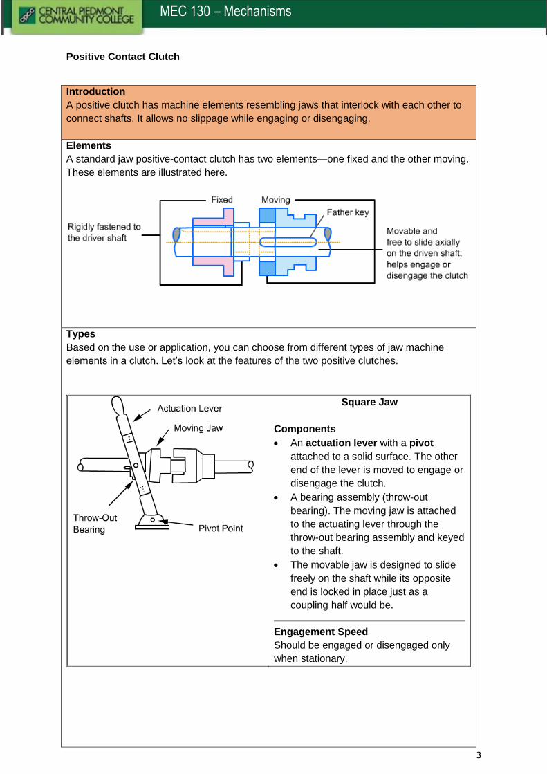
Elements
A standard jaw positive-contact clutch has two elements—one fixed and the other moving.
These elements are illustrated here.
Types
Based on the use or application, you can choose from different types of jaw machine
elements in a clutch. Let’s look at the features of the two positive clutches.
Square Jaw
Components
An actuation lever with a pivot
attached to a solid surface. The other
end of the lever is moved to engage or
disengage the clutch.
A bearing assembly (throw-out
bearing). The moving jaw is attached
to the actuating lever through the
throw-out bearing assembly and keyed
to the shaft.
The movable jaw is designed to slide
freely on the shaft while its opposite
end is locked in place just as a
coupling half would be.
Engagement Speed
Should be engaged or disengaged only
when stationary.
4
MEC 130 – Mechanisms
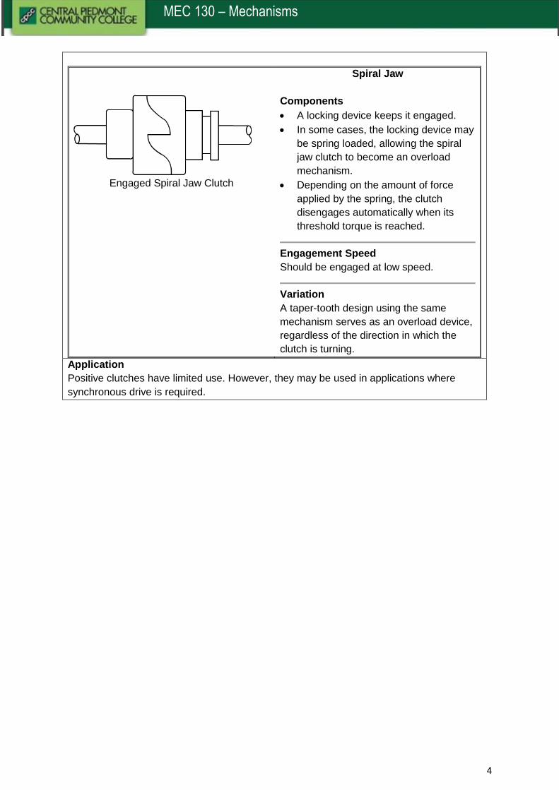
Engaged Spiral Jaw Clutch
Spiral Jaw
Components
A locking device keeps it engaged.
In some cases, the locking device may
be spring loaded, allowing the spiral
jaw clutch to become an overload
mechanism.
Depending on the amount of force
applied by the spring, the clutch
disengages automatically when its
threshold torque is reached.
Engagement Speed
Should be engaged at low speed.
Variation
A taper-tooth design using the same
mechanism serves as an overload device,
regardless of the direction in which the
clutch is turning.
Application
Positive clutches have limited use. However, they may be used in applications where
synchronous drive is required.

5
MEC 130 – Mechanisms
Friction Clutch
Introduction
Unlike positive contact clutches, frictional clutches can engage gradually. They can
transfer power smoothly regardless of the loads and speeds.
Factors Affecting Effectiveness
Types
There are two key types of friction clutches: Radial and Axial.
Radial Friction Clutch
In radial clutches, contact pressure is applied to the peripheral of a drum or rim. Here are
a few examples.
How It Works
The flexible friction band around a smooth
drum helps achieve braking when the
linkage tightens the band.
Band/Strap Brake
Advantages and Disadvantages
Easy to manufacture and use with
predictable performance
Unable to dissipate heat efficiently
Has uneven friction material wear
Has an open construction
•Coefficient of friction = Force pressing the objects together/Force that resists sliding
•The larger the value, the more the resistance to movement. However, clutch and brake liner material should be heat resistant.
Coefficient of Friction of the Mating Materials
•Increasing the surface area of the mating surfaces makes the clutch/brake proportionally more effective.
•Physical space requirements may limit the maximize size of a clutch/brake.
Surface Area
•Greater force pressing the clutch or brake surfaces together increases their effectiveness.
Amount of Force Used
6
MEC 130 – Mechanisms
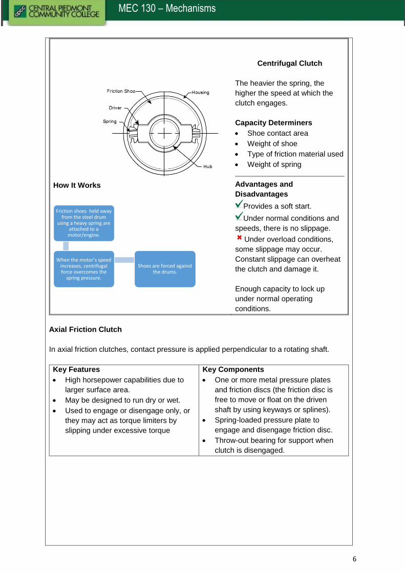
How It Works
Centrifugal Clutch
The heavier the spring, the
higher the speed at which the
clutch engages.
Capacity Determiners
Shoe contact area
Weight of shoe
Type of friction material used
Weight of spring
Advantages and
Disadvantages
Provides a soft start.
Under normal conditions and
speeds, there is no slippage.
Under overload conditions,
some slippage may occur.
Constant slippage can overheat
the clutch and damage it.
Enough capacity to lock up
under normal operating
conditions.
Axial Friction Clutch
In axial friction clutches, contact pressure is applied perpendicular to a rotating shaft.
Key Features
High horsepower capabilities due to
larger surface area.
May be designed to run dry or wet.
Used to engage or disengage only, or
they may act as torque limiters by
slipping under excessive torque
Key Components
One or more metal pressure plates
and friction discs (the friction disc is
free to move or float on the driven
shaft by using keyways or splines).
Spring-loaded pressure plate to
engage and disengage friction disc.
Throw-out bearing for support when
clutch is disengaged.
Friction shoes held away from the steel drum
using a heavy spring are attached to a
motor/engine.
When the motor’s speed increases, centrifugal force overcomes the
spring pressure.
Shoes are forced against the drums.
7
MEC 130 – Mechanisms
Here are a few examples of types of axial friction clutches.
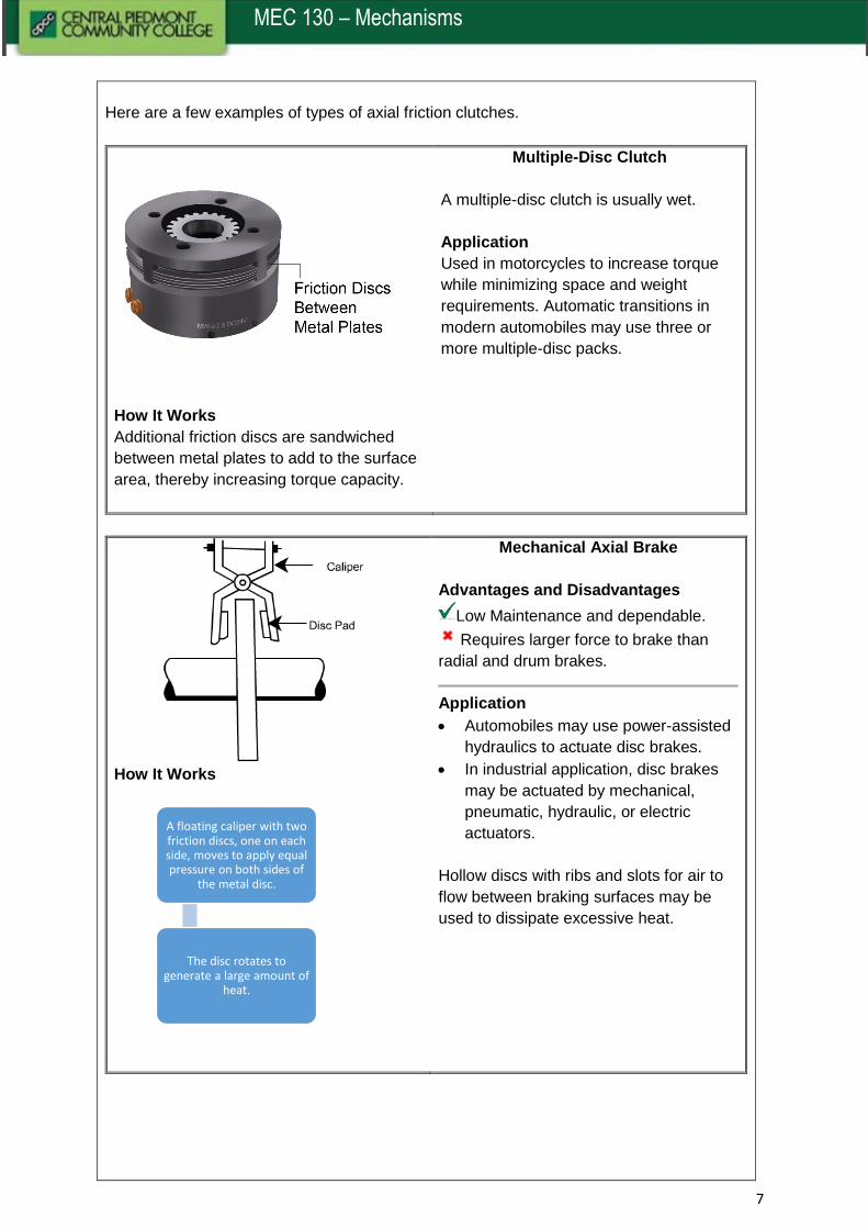
How It Works
Additional friction discs are sandwiched
between metal plates to add to the surface
area, thereby increasing torque capacity.
Multiple-Disc Clutch
A multiple-disc clutch is usually wet.
Application
Used in motorcycles to increase torque
while minimizing space and weight
requirements. Automatic transitions in
modern automobiles may use three or
more multiple-disc packs.
How It Works
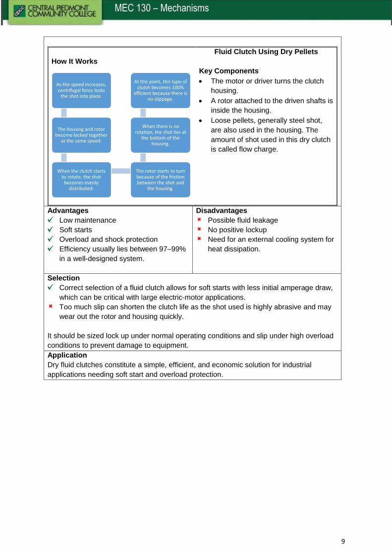
Mechanical Axial Brake
Advantages and Disadvantages
Low Maintenance and dependable.
Requires larger force to brake than
radial and drum brakes.
Application
Automobiles may use power-assisted
hydraulics to actuate disc brakes.
In industrial application, disc brakes
may be actuated by mechanical,
pneumatic, hydraulic, or electric
actuators.
Hollow discs with ribs and slots for air to
flow between braking surfaces may be
used to dissipate excessive heat.
A floating caliper with two friction discs, one on each side, moves to apply equal pressure on both sides of
the metal disc.
The disc rotates to generate a large amount of
heat.

8
MEC 130 – Mechanisms
Cone Clutch
Key Features
Cone clutches are a combination of
radial and axial type clutches.
Due to the wedging action of the
cone inside a matching drum, force
required for activation is less than in
purely radial or axial clutches.
Application
High-speed application with lower
horsepower requirements.
Fluid Clutch
Introduction
A fluid clutch uses liquid to transmit torque.
Elements
A impeller rotates and imparts energy by centrifugal force to a viscous fluid.
This fluid then imparts its motion to a runner attached to the output shaft.
The impeller and runner vanes have a small clearance between them, allowing a little
slippage, varying with the amount of fluid. The more the fluid, the less the slippage.
Variation
Another common industrial fluid clutch uses dry pellets called shot instead of oil or liquids
as the fluid media. Physically, it looks the same as a fluid clutch. Take a look at how it
works.
9
MEC 130 – Mechanisms
How It Works
Fluid Clutch Using Dry Pellets
Key Components
The motor or driver turns the clutch
housing.
A rotor attached to the driven shafts is
inside the housing.
Loose pellets, generally steel shot,
are also used in the housing. The
amount of shot used in this dry clutch
is called flow charge.
Advantages
Low maintenance
Soft starts
Overload and shock protection
Efficiency usually lies between 97–99%
in a well-designed system.
Disadvantages
Possible fluid leakage
No positive lockup
Need for an external cooling system for
heat dissipation.
Selection
Correct selection of a fluid clutch allows for soft starts with less initial amperage draw,
which can be critical with large electric-motor applications.
Too much slip can shorten the clutch life as the shot used is highly abrasive and may
wear out the rotor and housing quickly.
It should be sized lock up under normal operating conditions and slip under high overload
conditions to prevent damage to equipment.
Application
Dry fluid clutches constitute a simple, efficient, and economic solution for industrial
applications needing soft start and overload protection.
As the speed increases, centrifugal force locks
the shot into place.
The housing and rotor become locked together
at the same speed.
When the clutch starts to rotate, the shot becomes evenly
distributed.
The rotor starts to turn because of the friction between the shot and
the housing.
When there is no rotation, the shot lies at
the bottom of the housing.
At this point, this type of clutch becomes 100%
efficient because there is no slippage.
10
MEC 130 – Mechanisms
Magnetic Clutch and Brake
Introduction
Similar to dry fluid clutches, magnetic-article clutches use electricity to activate a clutch or
brake. They are used mainly for starting or stopping and are not suited for continuous slip
operation. Their horsepower capabilities range from fractional to several hundred.
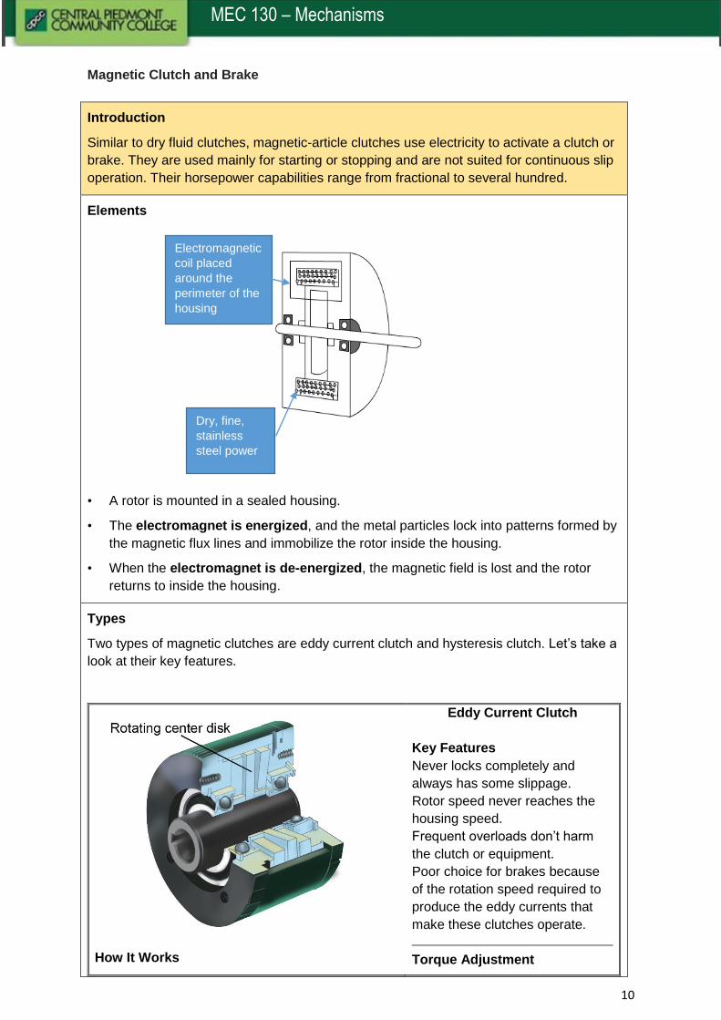
Elements
• A rotor is mounted in a sealed housing.
• The electromagnet is energized, and the metal particles lock into patterns formed by
the magnetic flux lines and immobilize the rotor inside the housing.
• When the electromagnet is de-energized, the magnetic field is lost and the rotor
returns to inside the housing.
Types
Two types of magnetic clutches are eddy current clutch and hysteresis clutch. Let’s take a
look at their key features.
How It Works
Eddy Current Clutch
Key Features
Never locks completely and
always has some slippage.
Rotor speed never reaches the
housing speed.
Frequent overloads don’t harm
the clutch or equipment.
Poor choice for brakes because
of the rotation speed required to
produce the eddy currents that
make these clutches operate.
Torque Adjustment
Electromagnetic
coil placed
around the
perimeter of the
housing
Dry, fine,
stainless
steel power
11
MEC 130 – Mechanisms
A non-contacting, non-ferrous rotor, usually
made of copper or aluminium, is sandwiched
between two magnetic discs mounted in a
housing.
The electric current induced in the rotor by the
magnetic field causes the rotor to rotate.
The torque can be adjusted by
misaligning the magnetic poles of
the two magnetic discs on either
side of the rotor.
Max torque obtained by north-
south magnetic-pole
arrangement.
Min torque obtained by north-
north and south-south magnetic-
pole arrangement.
Application
Eddy current clutches are used in
industries where overloads
frequently occur. They work well
in applications that require
constant torque but should never
be used in applications where
synchronization between input
and output is required.
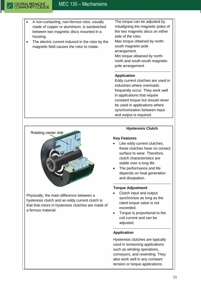
Physically, the main difference between a
hysteresis clutch and an eddy current clutch is
that that rotors in hysteresis clutches are made of
a ferrous material.
Hysteresis Clutch
Key Features
Like eddy current clutches,
these clutches have no contact
surface to wear. Therefore,
clutch characteristics are
stable over a long life.
The performance and life
depends on heat generation
and dissipation.
Torque Adjustment
Clutch input and output
synchronize as long as the
rated torque value is not
exceeded.
Torque is proportional to the
coil current and can be
adjusted.
Application
Hysteresis clutches are typically
used in tensioning applications
such as winding operations,
conveyors, and rewinding. They
also work well in any constant
tension or torque applications.
12
MEC 130 – Mechanisms
Selecting a Magnetic Clutch
Make sure that the heat generated by
cycling and slip doesn’t exceed a value
that would cause damage to the metal
powder.
Check with the manufacturer for
temperature limitations of specific
models of clutches/brakes.
Limitations
Rotational speeds that exceed
manufacturer’s recommendations will
generate excessive centrifugal force,
which causes the slip and torque to
become erratic.
In extreme cases, the clutch may even
engage due to centrifugal force, locking
the metal powder and rotor.
Application
Manufactured in a wide range of configurations and sizes, these clutches and brakes
may be integral to a motor or another piece of equipment or may be mounted
separately.
The lifespan of a carefully selected and sized clutch is excellent, without much
maintenance required.
These clutches are used in applications where rapid cycling is required.
This clutch forms a good choice for automated production processes as its lock-and-
unlock torque characteristics are consistent and predictable.