mechanical design and development of dc, rf … design and development of dc, rf accelerator and ecr...
TRANSCRIPT
N E W S L E T T E RFounder’s Day Special Issue October 2016
Mechanical design and development of DC, RF accelerator and ECR ion source programme
of APPD, BARC S. R. Ghodke, Rajesh Barnwal, Mahendra Kumar, Susanta Nayak, D. Bhattacharjee, J. Mondal, A. S. Dhavle,
Vijay Sharma, Shiv Chandan, Nishant Choudwary, R. I. Bakhatsing V. T. Nimje, K. P. Dixit, S. Acharya, P. Roychowdhury
Electron Beam Centre, Accelerator & Pulse Power Division
S.R. Ghodke is the recipient of the DAE Scientific &
Technical Excellence Award for the year 2014
Abstract:
APPD, BARC has taken up the indigenous design & development of high power electron accelerators for industrial, research and cargo scanning applications. Pulsed RF Linacs, with on-axis coupled cavity configuration, include the 10 MeV Industrial RF linac, 30 MeV linac for radiation streaming studies of fast breeder reactor as well as 6 MeV compact linac for cargo scanning applications. Industrial DC accelerators include a 500 keV Cockroft-Walton machine and 3 MeV Dynamitron. Several radiation processing applications, such as material modification, waste water treatment, flue-gas treatment, etc. have been demonstrated using these accelerators. 6 MeV linac for cargo-scanning have been successfully commissioned and are being characterized for the required x-ray output. For ADS studies, a 50 keV, 50 mA ECR Ion Source is fabricated including low energy beam transport line. This paper presents the details of the mechanical design and fabrication of these accelerators.
Mechanical design, fabrication and development of components of different programme of APPD are as given below.
1. 6 MeV Compact Linac:
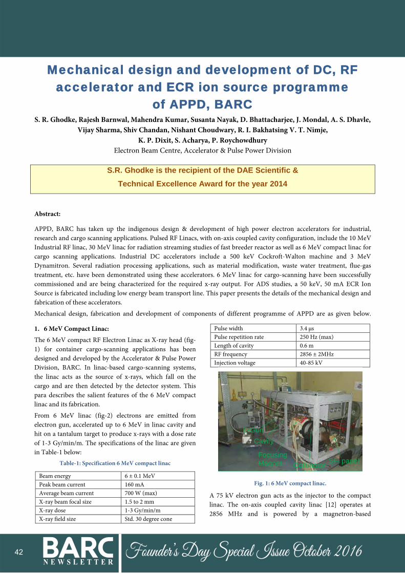
The 6 MeV compact RF Electron Linac as X-ray head (fig-1) for container cargo-scanning applications has been designed and developed by the Accelerator & Pulse Power Division, BARC. In linac-based cargo-scanning systems, the linac acts as the source of x-rays, which fall on the cargo and are then detected by the detector system. This para describes the salient features of the 6 MeV compact linac and its fabrication.
From 6 MeV linac (fig-2) electrons are emitted from electron gun, accelerated up to 6 MeV in linac cavity and hit on a tantalum target to produce x-rays with a dose rate of 1-3 Gy/min/m. The specifications of the linac are given in Table-1 below:
Table-1: Specification 6 MeV compact linac
Beam energy 6 ± 0.1 MeV Peak beam current 160 mA Average beam current 700 W (max) X-ray beam focal size 1.5 to 2 mm X-ray dose 1-3 Gy/min/m X-ray field size Std. 30 degree cone
Pulse width 3.4 µs Pulse repetition rate 250 Hz (max) Length of cavity 0.6 m RF frequency 2856 ± 2MHz Injection voltage 40-85 kV
Cavity
FocusingMagnet
E-Gun
CollimatorSF6 panel
Fig. 1: 6 MeV compact linac.
A 75 kV electron gun acts as the injector to the compact linac. The on-axis coupled cavity linac [12] operates at 2856 MHz and is powered by a magnetron-based
42

N E W S L E T T E RFounder’s Day Special Issue October 2016
microwave power source [5MW(pk)/3 kW(avg)]. An electromagnet with eight pancake coils in series is used to focus the beam to a focal spot of diameter less than 2 mm. A water-cooled tantalum X-ray target is used to produce the required dose of x-rays. A collimator with slit of 4 mm width produces the 30º cone shaped x-ray field. Turbo-backed sputter ion pumps [13] are used to achieve vacuum level of 1x10⁻⁷ mbar in the linac. PLC-based control and instrumentation system enables remote operation of the linac. DM cooling water system provides cooling for linac, microwave components, focusing coils of the electromagnet and target.
The 6 MeV compact linac has been fabricated and installed. Beam trials on the 6 MeV compact linac have indicated that the linac performance shows a satisfactory trend.
Following components are mechanically designed, fabricated and installed inside rack of 6 MeV X-ray source.
Fig.2 : 6 MeV compact linac model.
Fabrication of Electron Gun for 6 MeV X-Ray Source:
In linac-based cargo-scanning system, to work electron gun (fig-3) on a movable system, it has to be robust. Electron gun is to work at 10-7 mbar vacuum and 2000 degree Celsius cathode temperature.
341.
00
Ø203.00
2 PIN FEED THROUGH (12 KV, 185 A, Ø6.4 DIA.COPPER WITH FLANGE (DN 35 CF-F )
75 KV CERAMIC ISOLATOR
FILAMENT CONNECTOR
CATHODE HOLDER CUP
GRID
ANODE
CATHODE (LaB6)
HEAT SHIELD
Fig-3: Compact electron gun Assembly.
An effort is made to engineer the gun assembly to make it more robust, easy removal of filament and alignment. Many components are indigenously developed like SS 316 grid, Ceramic insulating ring, Tantalum thermal shield, Tungsten filament and filament guide etc. All above components are to work at 800 to 2500 degree Celsius. Filament connector is made from Invar to reduce heat loss and to make rigid connection. Invar was CNC machined and wire cut by EDM. Invar and Copper electrode feed through is shrink fitted with the help of liquid Nitrogen. Shrink fit (fig-4) tolerances of 15 micrometer are achieved by jig boring machining processes. Tantalum cup for LaB6 cathode and heat shield are made from die and punch mechanism. For alignment of electron emitter with beam axis this Tantalum cup is a crucial component. Electron gun is assembled and aligned its components with the help of precision jigs (fig-4). The whole assembly was Helium leak tested by MSLD up to 4 x 10⁻¹⁰ mbar.l/s vacuum, no leak was found.
Precision hole in the invar for shrink fit tolerance, Jig boring process is used.
Fig.4: Shrink fitting of two Copper pin feed through with Invar
connector and alignment fixture.
Fabrication of cathode holder and heat shield:
Tantalum cups for cathode holder and heat shield housing (fig-5) are to be made from die and punch as shown in figure 3. In the initial trial cups were breaking because of excessive deformation. Then draw the cup in three stages with control deformation by using hydraulic press. The fresh dies are made and trials are taken, it is found that heat shield cups are drawn after few failures as shown in figure 4 and 5. Cathode cup trial is also taken and found it is forming but bend radius was more than 2 mm and also
43

N E W S L E T T E RFounder’s Day Special Issue October 2016
wrinkling on the flange face. The dies were further corrected and cups are drawn. The final tolerances and design parameters are achieved by machining.
Tantalum heat shield
16.6
0
Ø18.80
Rhenium holder
Tantalum cup
Tungsten filament
LaB6 pallet (Cathode)
Ceramic sleeve
Fig. 5: Cathode holder & heat shield assembly
Fabrication of Tungsten filament:
Tungsten filament (fig-6) of spiral shape of 4 turns within 10 mm circle made from Tungsten wire of diameter 0.5 mm. Tungsten Filament is made from M/S Plansee India Pvt. Ltd. as per prescribed tolerances by Tungsten wire as shown in (fig-6).
Fig. 6: Spiral Tungsten Filament
Alignment
Special jig and fixtures are made to ensure the alignment (fig-4) of grid, cathode and anode assembly within 50 micrometers as shown in figure 6, 7 and 8. Design and development of primary collimator for 6 MeV X-ray source:
The primary collimator (fig-7&8) is designed to function with a 6 MeV x-ray source for cargo scanning application. It is installed and tested with linac. The accelerated electron beam hits a tungsten target and x-ray generated though the target is fed to the collimator. Thereafter, collimated high energy x-rays will be used for cargo scanning. The collimator plates are made up of mild steel blocks of is 2062 grade ensuring high geometrical stability. Each plate has been machined with high precision electric
discharge machining (EDM) and surface grinding processes. The assembly rods are hard chrome plated to provide corrosion resistance and increase surface hardness. It is aligned with x-ray source and being use for linac experiments. Fig-6 shows EDM wire cut plates with alignment gauge.
Fig. 7: Assembly of collimator plates with alignment gauge.
It is used for qualification of linac by ANSI object. The collimator assembly after mounting on support will be required to move in x, y, z direction and angularly so as to achieve desired shape of the X-ray beam and to align it with X-ray beam coming from 6 MeV Accelerator.
Fig.8: Primary collimator assembly.
After assembly all the eight number of plates, the whole assembly mounted on a mild steel support structure having two numbers of bearing with housing of size 360 mm OD for easy rotation through the central axis of the collimator. The support structure also equipped with a worm and worm wheel gear arrangement for fine control the rotation of collimator which is powered by a stepper motor.
44

N E W S L E T T E RFounder’s Day Special Issue October 2016
Fabrication of accelerator tank and SF6 gas handling system of 3 MeV DC Accelerator:
The 3 MeV Accelerator Project (fig-9) involves designing, fabrication, installation and commissioning of a 3 MeV, 30 kW Industrial Electron Beam Accelerator with a terminal voltage of 3 MV and is housed inside the Electron Beam Centre building at Kharghar, Navi Mumbai. For ecological and economical reason, the SF6 gas is reincorporated into closed cycle.
SF6 Gas Handling System of 3 MeV project mainly covers SF6 gas transfer system including accelerator tank & storage tank and SF6 gas cooling system. The aim of the SF6 gas handling system is to introduce the gas at high pressure to the accelerator tank after evacuation and to bring back into the storage tanks with minimum loss. The gas handling system also provides purification of gas, prevention from mixing with air or any other substances, which may contaminate and thus bring down the high voltage insulation characteristics of the gas. A heat load of 12 kW is coming due to high frequency transformer, electron gun, power supplies, blower motor etc. A radiator type heat exchanger with centrifugal blower and finned tube has been used for cooling the gas.
Accelerator tank:
Accelerator pressure vessel is the main body of the 3 MeV Accelerator (fig-9) which will house high voltage multiplier columns, RF electrodes, corona shields, high voltage terminals, electron gun, accelerating tubes, motor generator set, heat exchangers, RF transformer etc. Normal operating pressure inside the accelerator is 6 kg/cm2. The accelerator tank has to be evacuated to vacuum of 10-1 torr before filling the gas. Detail design and fabrication of the accelerator pressure vessel using ASME B&PV SEC-VIII, DIV-1 Code was carried out.
SF6 gas transfer system:
SF6 gas transfer system (fig-10) has 150-meter long pipe line of 3” size pipeline, compressor, vacuum pump, dryer, filter, heater and blower.
SF6 compressor is a non lubricating type, vertical double acting, single stage air compressor de-rated for SF6 use with a free air delivery of 55 CFM and a maximum discharge pressure of 125 psi (g). The 3000 LPM capacity rotary vacuum pump is used to pump all the gas remaining in the tank after one atm. pressure, which is supplied to compressor and then transferred to storage tank. About 0.5 Torr vacuum is achieved in the accelerator tank, storage tanks and pipeline.
Vertical vessel twin column activated alumina filled dryer is used for removal of moisture and breakdown products. Coarse and fine filters are provided to make sure that dust free gas is circulated through the accelerator column.
Fig-9: 3 MeV Accelerator tank & RF tank.
Fig.10: SF6 Gas Transfer System.
SF6 gas cooling system:
This system is mainly comprises of 1.5” and 1” SS pipe line, radiator type heat exchanger and blower combination, 5 ton chiller unit, cooling tower, pressure transmitter, temperature sensors, safety interlocks, flow meter, pressure gauges and other instrumentation.
45

N E W S L E T T E RFounder’s Day Special Issue October 2016
Fig.11: Rectangular Radiator Type Heat Exchanger
inside the Accelerator Tank. The centrifugal blower has been designed and commissioned to achieve special heat transfer requirements under 6-kg/cm2 pressures of SF6 gas. Finned tube heat exchanger with header have been designed and fabricated suitable for inside space of accelerator tank (Fig-11) Heat exchanger assembly is made of such four numbers of bundles and makes an enclosure of size 1100 x 1100 x 150 mm.
HEAT EXCHANGER
CHILLER CONDENSOR
COOLING TOWER
CHILLER UNIT
COOLING TOWER
Fig.12: SF6 Gas Cooling System.
Detailed chilled water flow and heat transfer calculations were done to make sure that high voltage RF Transformer, which is having a maximum heat load of 6-8 kW, is maintained within the permissible temperature limit. It was estimated that a total flow rate of 50 lpm of chilled water at 220C is required through the heat exchanger for cooling (fig-12) of transformer inside the accelerator tank. Similarly other accelerator components having a maximum heat load of 3 kW requires a flow rate of 20 lpm of chilled water at 100C.
In fabrication of SF6 gas handling system we have carried out material test, welding test, hydro & pneumatic test, compressor & blower performance test and chiller performance test.
Fabrication of Buncher Cavity for 30 MeV Linac:
BARC has developed 2856 MHz, 04 cell RF Buncher cavity (Fig-13 &15) required for 30 MeV RF Linac project and it will be proposed to use for Neutron generation. New vendors are developed for fabrication techniques and its successful implementation in Buncher cavity. The fabrication process consists of material procurement, CNC Diamond turning of cavity, preparation of slot for vacuum brazing wire, CNC milling, chemical cleaning, vacuum furnace brazing, Copper-stainless Steel joints, development of fixtures for brazing, various brazing parameters, brazing cycle and helium leak testing etc.
Fig. 13: ETP Copper brazed cavity sample for tensile test.
Water jacket (Fig-14) for cavity cooling is designed such a way that it can be welded with brazed cavity. Performance of resonant frequency of cavity was measured.
Fig.14: Assembled water cooling jacket with welding lip.
Fig.15: Buncher cavity.
46

N E W S L E T T E RFounder’s Day Special Issue October 2016
CNC Machining of Copper cavity
Copper cavity is required for different RF Linac projects. CNC Diamond Turning shown in (fig-16) and milling at high accuracy are performed in modern machining workshops to achieve better quality factor of cavity of Linac and mirror finish. Additionally special care has been taken to guarantee good ultra high vacuum and high electric field performance of the finished cavity. For rough machining CNC Spinner lathe machine is used and for final machining CNC Diamond turning machine is used with single crystal and poly crystal Diamond tools.
Fig.16: Internal Diamond turned cavity.
Surface Finish
Internal surface finish should be very good to reduced RF power losses and to improve quality factor of cavity. Skin depth for current of RF power is approximately 1 micrometer. Roughness average (Ra) value of 20 nanometre or better asked in DTM machining. During our inspection we have achieved surface finish 8-15 nanometre of DTM machined cavity. White light interferometer is used for measurement of surface roughness as shown in fig. 3. All brazing surfaces have surface finish of 0.8 micrometer for better brazing.
Vacuum furnace brazing of OFHC Copper cavity
Fig.-17: ETP Copper tensile test of brazed cavity specimen.
Rough machined Copper cavity is annealed for removal of machining stresses. It is heated up to 400 degree Celsius in vacuum furnace and given one hour soaking time. Working vacuum of furnace should not be less than 5 X 10⁻⁵ torr in any point of annealing and brazing cycle. Heating rate should not more than 5 degree Celsius per
minutes and vacuum maintain as mentioned above. During vacuum detoriation, hold the job at constant temperature unless good vacuum is achieved.
BVAg-8 Eutectic alloy of melting temperature 7800 Celsius, with 72% Silver and 28% Copper is used in brazing of Copper cavity. BVAg-30 alloy of with 67.63% Silver, 27.54% Copper and 4.82% Palladium is also used.
Two samples of brazed cavity are tensile tested to find out ultimate tensile strength of brazed cavity. It is shown in (fig-17). We achieved strength of 95 MPa. Brazed copper cavity tested by radiographic method for brazed material flow analysis. One brazing joint found to be over flowed and not properly filled with brazing material of BVag-8.
Successful vacuum brazing of prototype OFE Copper cavity are done. The brazed cavities are leak tested by using Helium leak detector. Leak tightness of the brazed joints found was better than 5x10⁻¹⁰ mbar-l/s. Water jacket is fabricated and seen its fit up.
Design and fabrication power feed cavity test setup for various linac:
In a RF electron linac a power is fed to the linac structure through a power feed cavity that connects the waveguide with the accelerating cavity through a coupling aperture. The amount of power fed to the linac depends on the coupling coefficient between cavity and the waveguide that is decided by the size and shape of the coupling aperture. The requirement of coupling coefficient changes with the energy and current in the accelerator. The optimization of the power feed cavity and the coupling aperture to attain required coupling at a required resonant frequency is a tedious task. Our experience shows that improper RF contacts lead to change in resonant frequency and hence the coupling coefficient. Also a frequency shift and change of coupling coefficient is observed in the linac structure in brazed and unbrazed condition. Thus a power feed (PF) test set-up consisting of 8 accelerating cells, 8 coupling cells and one power feed cavity is fabricated.
Also it will be used to study the change in resonant frequency and coupling coefficient with the application of external pressure/load. A load cell (fig-18) is assembled to see the applied load. Pressure transmitter and pressure gauge shows the applied pressure with hydraulic power pack. Hydraulic power pack can give 2.5 ton compressive load in assembly. Special and unique bead bull arrangement is made to do the in situ RF measurement during applied compressive load. Pulley of bead pull run by stepper motor control with PLC display. PLC also shows the load, pressure, bead position etc. It will be simulating the brazed structure in unbrazed condition.
47

N E W S L E T T E RFounder’s Day Special Issue October 2016
Cavity fabrication requires chemical, micro, macro testing of oxygen free electronic (OFE) Copper.
THK make LM bush and LM rod made of high carbon-chromium bearing steel and hardness of HRC 58 to 64, straightness of shaft is 50 µm /300 mm or less and precision of fitting between shaft and bush is g5- h5 grade. It has 150 mm long linear motion bush, 1 meter long linear motion rod of diameter 40 mm and end flange fittings. Four numbers of linear motion rods are fixed between two plates of thickness 18 mm and 14 mm, between above two plates one more plate of thickness 14 mm is assembled and it will move up and down with the help of hydraulic cylinder. Hydraulic pressure system is designed based on experiment through which we will get idea about load/stress at which, further no change in frequency and coupling coefficient. As per literature 1 to 2 ton load is sufficient.
PF test set up assembly (fig-20) requires CNC diamond turning for nano machining of cavity in addition to different machines like CNC electric discharge machining (wire cutting), CNC ultra precision lathe machining, CNC vertical milling centre etc for ultra precision work. This involves a lot of tool design and developmental work. Critical instruments like coordinate measurement machine (fig-19), master height gauge, white light interferometer etc is required for metrological inspection. Cavity material used as oxygen free electronic (OFE) Copper UNS No-10100 of purity 99.99 % and Oxygen content is less than 5 ppm.
Fig.18: Load Cell for 2.5 ton load and assembled
cavity before brazing.
Fig. 19: Co-ordinate measurement of cavity and surface roughness measurement by white light interferometer.
Copper plating required for SS flange and wave guide (284). SS should be plated with Nickel and then with Copper. Total plating thickness more than 5 µm but less than 10 µm is used.
Alignment is most important for smooth assembly under heavy loads. Proper tool and fixture is used to get assembly alignment 10-20 micrometer.
All dimension and contour of the cavity is measured in Co-ordinate Measuring Machine (CMM). Parallelity of half cell cavity achieved within 5 micrometer. Bigger equator diameter of 82.66 mm is achieved within 10 micrometer. Concentricity of cavity achieved within 10 micrometer. RF frequency measured in VNA of complete assembly (17-cell assembly, 8 accelerating, 8 coupling and one power feed) with power feed is 2.85615 GHz in ambient and coupling co-efficient measured 2.44.
Fig.20: Power feed test set up assembly in workshop.
Power feed (PF) test set up assembly (fig-20) to test different parameters of power feed cavities is fabricated. Cavities are brazed and its RF measurement is done.
ECR ion source for LEHIPA:
A three electrode ECR proton source (fig-21) has been developed for LEHIPA from local vendor [1] and 42 mA of hydrogen beam current was extracted at 40 keV. A low energy beam transport line has been fabricated also from Indian vendor for measuring beam profile, beam emittance and proton fraction.
Fig: 21: ECR Ion source under leak testing
48

N E W S L E T T E RFounder’s Day Special Issue October 2016
Acknoledgment
Authors are grateful to R. K. Rajawat, Dr. L. M. Gantayet, Dr. K. C. Mittal, D. P. Chakravarthy, Dr. A. K. ray, Dr. Archana Sharma, Dr. A V Bapat, Shri E Kandawsami and Shri M N Jha, D. K. Sharma, Raheim N. Rajan, S. K. Srivastava, S. P. Dewagan, Vivek Yadav, A. R. Tillu, R. B. Chavan, Mukesh Kumar, Rajnish Tiwari, S. R. Barje, N. K. Lawangare, BARC for their guidance and support.
References
1. "Machining and brazing of accelerating RF cavity", S R Ghodke, R. Barnwal, Mahendra Kumar; S. Nayak, D. Bhattacharjee; R. Tiwari, D. Jayaprakash, R L Mishra, K C Mittal, B K Dutta, L M Gantayet, Published in IEEE Conference Series, , pages 557 - 560, Sept. 28 2014-Oct. 3 2014, Mumbai, India, [2014]
2. "Fabrication of compact electron gun for 6 MeV X-ray source", S R Ghodke, R. Barnwal, Mahendra Kumar; S. Nayak, D. Bhattacharjee; R. Tiwari, D. Jayaprakash, R L Mishra, K C Mittal, B K Dutta, L M Gantayet, Published in: IEEE Conference Series, , pages 101 - 104, Sept. 28 2014-Oct. 3 2014, Mumbai, India, [2014]
3. “Design and experiments of RF transverse focusing in S-Band, 1 MeV standing wave linac”, Authors: J. Mondal, , Shiv Chandan, S. Parashar, D. Bhattacharjee, A.R. Tillu, R. Tiwari, D. Jayapraksh, V. Yadav, S. Banerjee, N. Choudhury, S.R. Ghodke, K.P. Dixit, V.T. Nimje, published in Nuclear Instruments and Methods in Physics Research Section-A, Accelerators Spectrometers Detectors and Associated Equipment. Volume 795, 21 September 2015, Pages 343–350. [2014].
4. "Cooling of high pressure insulating gas for 3 MeV DC accelerator: an alternate approach at EBC Kharghar", S R Ghodke, Rajesh Barnwal, Mahender Kumar, Susanta Nayak, Vijay Sharma, S. K. Srivastava, Satyanarayan Acharya, K. P. Dixit, Israel Bakht Singh, D. Jayaprakash, Rehim Rajan, D. K. Sharma, S. Dewangan, K. C. Mittal, L. M. Gantayet, International Linear Accelerator Conference, (LINAC14), CERN, Geneva, Switzerland., [2014].
5. “Fabrication of Buncher Cavity with Water Jacket”, S R Ghodke, Jayanta Mondal, Sonali Parashar, Rajesh Barnwal, K. C. Mittal and L. M. Gantayet, InPAC-2013-ID-038, 19-22 Nov. 2013, held at VECC, Kolkata. [2013].
6. "Mechanical Design and Fabrication of Power Feed Cavity Test Setup", S. R. Ghodke, A. S. Dhavle, Vijay Sharma, Shreya Sarkar, V. T. Nimje, K. C. Mittal and
L. M. Gantayet, Indian Particle Accelerator Conference, InPAC-2013-ID-134, 19-22 Nov. 2013, held at VECC, Kolkata. [2013].
7. “Testing and Operation of SF6 Gas Handling System for 3 MeV, 30 kW Electron Beam Accelerator at EBC, Kharghar, Navi Mumbai”, S R Ghodke, D. Jayaprakash, Rajesh Barnwal, Mahendra Kumar, Susanta Nayak, KC Mittal and L M Gantayet, International Conference and Piping, OPE 2013, ID: C-011, Kalpakkam, INDIA. [2013].
8. “Commissioning and Beam Trials of 6 MeV RF Electron Linac For Cargo Scanning”, Shiv Chandan, N. Chaudhary, S.R. Ghodke, D. Bhattacharjee, V. Sharma, J. Mondal, R.B. Chavan, V.Yadav, A.R.Tillu, V.T. Nimje, S. Acharya, K.P. Dixit, K.C. Mittal and L.M. Gantayet, InPAC-2013-ID-019, 19-22 Nov. 2013, held at VECC, Kolkata. [2013].
9. “Design, Fabrication and VNA Testing of an Auto-Focusing Buncher Section for 40 keV, 500 mA DC Electron Beam Injection”, J. Mondal, S. Parashar, S. R. Ghodke, K. C. Mittal and L. M. Gantayet, InPAC-2013-ID-081, 19-22 Nov. 2013, held at VECC, Kolkata. [2013].
10. “Design and Development of Compact Electron Gun And its Performance with Compact Linac Operation”, D. Bhattacharjee, R. Tiwari, D. Jayaprakash, R. L. Mishra, Shiv Chandan, A. R. Tillu, V. Yadav, S. R. Ghodke, K. C. Mittal and L. M. Gantayet, InPAC-2013-ID-266, 19-22 Nov. 2013, held at VECC, Kolkata. [2013].
11. “Design and development of collimator for 9 MeV BARC-ECIL Linac”, Authors: S.R. Ghodke, et. all, Published in Proc. Symp. on Indian Particle Accelerator Conference (InPAC-2011), Delhi, India., during February 15-18, [2011].
12. “Five electrode ECR proton source for LEHIPA”, Authors: P. Roychowdhury, S. R. Ghodke, D. P. Chakravarthy, Abhay Kumar, J. J. Roy, and S. Guha, Published in Proc. Symp. on Indian Particle Accelerator Conference (InPAC-2011), Delhi, India., during February 15-18, [2011].
13. D Bhattacharjee, R Tiwari, et al, “Development of Electron Guns for Linacs and DC Accelerator “J of. Phys, Vol 390, 390 012071 (2012).
14. Shiv Chandan, N. Chaudhary, S.R. Ghodke, et al, “Commissioning and Beam Trials of 6 MeV RF Electron Linac For Cargo Scanning”, InPAC-2013, Kolkata.
49

N E W S L E T T E RFounder’s Day Special Issue October 2016
15. Ghodke S. R, et. al. “Tank Design for 3 MeV, 30 kW Industrial Electron Accelerator”, InPAC 2003, p-249.
16. R.C.Sethi, V.T.Nimje, M.Sengupta, A.J.Dabeer, K.P.Dixit and P.H.Ron, “Design and Development of 10 MeV RF Electron Linac for Applied research and Industrial Applications”, Proc.APAC98
17. D.Jayaprakash, et al, “Renewable Vacuum System of the compact linac”, this conference
18. P. Roychowdhury et al, “High Intensity ECR Proton Source Development for LEHIPA”, InPAC’09, RRCAT, Feb. 10-13 (2009).
19. V.T.Nimje et. al., “Design and development of 30 MeV, 3 kW RF electron linac” APAC 2007, RRCAT, Indore, India.
50