mechanical equipment - cern document servercds.cern.ch/record/1246521/files/p251.pdfand torsional...
TRANSCRIPT
MECHANICAL EQUIPMENT
G. MoritzGSI, Darmstadt, Germany
AbstractMechanical equipment is an integral part of each magneticmeasurement. In this contribution the importance of mechanicaltolerances is demonstrated with some examples and the principal rulesin order to reduce the influence of mechanical errors are discussed. Inthe second part typical benches are presented for almost everymeasurement task. In the appendix a non-complete list of companieswhich produce or sell mechanical equipment is given.
1. INTRODUCTION
The successful operation of an accelerator requires:� extremely tight magnetic field tolerances which have to be proved by measurements� a proper alignment of the magnets
Thus we need mechanical equipment� to check the mechanical tolerances of the magnets� to make accurate magnetic measurements� to set precise fiducial marks which are accessible after the installation of themagnets in the accelerator
In the field of magnetic measurements the mechanical equipment is mainly used for thepositioning and moving of the sensor (coil , Hall probe etc.). Its specific design depends on theapplications, i.e. on the field property we want to measure (transfer function, field boundary,field quality etc.), on the accuracy that is required, and on the shape and the symmetry of themagnetic field.
2. THE INFLUENCE OF MECHANICAL TOLERANCES ON THE ACCURACY OFMAGNETIC MEASUREMENTS
The accuracy required for magnetic measurements leads usually to very tightmechanical tolerances. I will demonstrate this with four examples.
2.1 Rotating harmonic coil
The influence of the mechanical errors on the results of magnetic measurements with arotating harmonic coil i s covered theoretically in several publications [1–3]. The main sourcesof measurement errors during coil operation are:� error due to transversal displacement of the rotational axis� error due to angular shifts
These effects depend on the angular position.

ëTransversal displacementí is caused by the coil not rotating in a perfect circle due tosag and bow-effects and imperfect bearings. This error is not important for dipoles.
ëAngular shiftí means azimuthal vibrations induced by a lack of stiffness of the shaftand couplings or by the stepping motor. This effect influences the results for quadrupoles anddipoles as well .
These mechanical imperfections lead to errors in the measured harmonic coeff icients.The relation is given in the following formulas� �� � �b
nb b a an k n k n k k n k n k
k
� � � � � � � � �� �
2 1 1 1 11
( ) ( )| | | |� �� � �an
a a b bn k n k n k k n k n kk
� � � � �� � � � � � � ����
2 1 1 1 11
( ) ( )
for transversal displacement
Displ � �� � � � ��
R k kref k kk � � � �cos( ) sin( )
and by !� " �b
na a b bn k n k n k k n k n k
k
# $ $ %& ' & '()*
2 1
( ) ( )| | | |
+ ,� " �an
b b a an k n k n k k n k n kk
# % $ $ %& ' & '()*
2 1
( ) ( )
For angular shifts [2].
+ ,� � " � � �meas k kk
k k# $ $*cos sin-
i, . i are the relative amplitudes of the distortion and bi, ai are the normal and skew fieldcoeff icients.
A field harmonic present in the magnet can introduce erroneous terms of higher andlower orders, and the error is basically given by the product of the amplitude of the harmoniccoeff icient and the error amplitude. Thus the main contribution is due to the main fieldcomponent.
In order to reach a relative accuracy of the higher harmonic coeff icients of the order of10-4 we need for example, at a typical radius of 40 mm, a stabilit y of the axis of some / m anda precision of the angular measurement better than 0.1 mrad.
It is almost hopeless to fulfil these conditions.
2.2 Mapping of the Electron Cooler solenoid
In an Electron Cooling device the ëwarmí ion beam is cooled down by a ëcoldí electronbeam. By elastic Coulomb colli sions between electrons and ions travelling together throughthe field of the cooler solenoid the velocity distribution of the ion beam is reduced, the beamgets colder. Good cooling eff iciency requires a very high field homogeneity of this solenoidalfield. Especially criti cal are the transverse field components, because these limit the reductionof the transverse velocity. It is almost impossible to build a solenoid with transversecomponents smaller than 0.1% of the main longitudinal component. Thus, so-called correctionwindings are usually installed in order to compensate for the transverse components.

The solenoid is 2–3 m long and the variation of the transverse components relative tothe main component should be less than 0.01%. We at GSI used a 3D probe head with threeHall probes (Fig. 1). The very criti cal mechanical requirement is that the orientation of theprobe head in front of a 4-m long cantilevered beam must be stable within about 0.01 mrad.Otherwise the main component would lead to a wrong measurement of the transversecomponent. That demands very high accuracy and stabilit y of the stage that is used. Using themirror in front of the probe head we check this regularly by autocollimation, i.e. by measuringthe angle between the incident and reflected light.
Fig. 13D probe head with three orthogonal Hall probes
2.3 Mapping of an Insertion Device
The field of an Insertion Device (ID) (wiggler or undulator) should not disturb theclosed orbit of a stored beam, that means that an electron should neither be deflected nortransversely displaced. This leads to the requirements that the first and second field integralhave to be zero, i.e. 0
B(s) ds = 0 and
0 0B(s¥) ds¥ ds = 0
Thus these field integrals have to be measured. The measurement errors typically have to beless than 100 G•cm and 100 G•cm2 respectively.
One method that measures both the local and the integral fields is the mapping of the IDpoint by point in the longitudinal direction. The integral field is numerically calculated bysummation over the point measurements:
B dz B zi i1 2 134 5
The integral reproducibilit y error is given by5 5 5B dz B z Nrms6 7 6 68
where N is the number of points, 5
z the step width and 5
Brms the rms error of every pointmeasurement.
Let us consider only the field error due to erroneous positioning:

I use as an example the Advanced Light Source (ALS) Insertion Device 9 4, 5: : It is5.5 m long, ; z†=†0.22 cm, N†=†2500, maximum field 0.9 T, wavelength < †=†5.0 cm. Thefield oscill ates rapidly with the wavelength < between -0.9 T and +0.9 T.
The error of the local field measurement due to a position uncertainty = z is given by theformula:
dB Bz
z> ? ? ? ?0
22
@A B A Csin( )
and DB B
zrms E F F0
2
2B C A
With the position reproducibilit y C z of 1†µm we get
D†Brms =†0.8 G and the contribution
to the integral error by the position accuracy only is 10 G•cm.
2.4 Measurement of the integral field strength GHBdl with the stretched wire method
When a stretched wire is moved transversely through a magnetic field by a distance dx,the flux through the wire loop changes and a voltage V is induced that can be integrated:
Bdl I 1
dx* Vdt
JJOne sees immediately that the relative error of the position has to be of the same order
as the desired accuracy of the integral field. A relative integral field accuracy of 10-4 and a stepwidth of 10 mm requires a precision of the position measurement of 1µm.
3. STRATEGIES FOR REDUCING THE INFLUENCE OF MECHANICALERRORS
3.1 Use the best and most suitable equipment you can get
For example:K good spring-loaded bearings for the minimisation of transverse vibrationsK good encodersK interferometer for position measurementK DC motors instead of stepping motors to reduce torsional vibrations
Do the components also operate properly in a high field and low temperature environment?
3.2 Use the appropr iate materialK no magnetic materialK no conducting materialK high torsional stiffness (for example for the shaft and coupling of the rotating coil ,100†Nm/mrad)K high bending stiffness for a long cantilevered beam (good modulus/weight ratio)

3.3 Measure the correct sensor position
The position or orientation of the sensor (Hall probe/coil etc.) should be measured asclose to the sensor as possible. That means for example:L place the encoder near the rotating coilsL place the mirror for autocollimation measurements close to the Hall probe headL place the interferometer reflector correctly for accurate position determination
3.4 Use intelli gent design
The components may not be available on the market or are too expensive, the tolerancesin machining are too tight.L bucking coils compensate the main harmonic and thus reduce the influence of lateral
and torsional vibrations on the measurement resultsL damp the vibrations of the motor/gear by flexible couplingL vertical orientation of the rotating coil/stretched wire avoids the influence of sagL double search coils for gradient measurement are independent of the positionaccuracy
3.5 Use another method
A general strategy should be to double check the results by several methods!L instead of mapping: stretched-wire methodL instead of stretched wire: flip- or search-coil methodL instead of mapping the three components of the field, measure the orientation of thefield by a compass needle M 6N (Fig. 2)

Fig. 2ëCompass needleí for the measurement of the orientation of the magnetic field
3.6 Measure the errors
If you cannot get the required precision of your equipment, then you have to measurethe errors and correct for:O systematic errors which can be measured off- line and corrected for later using
calibration tablesO random errors which can be measured on-line
For example: Calibration of the 3D Mapper stage versus on-line measurement byautocollimation and/or interferometer.
3.7 Average the results
By appropriate averaging over different orientations mechanical errors will cancel out:O offset of the inclinometerO misalignment of a Hall probe can be checked by a rotation of 180•O coil orientation (relative to gravity) can be found by end-to-end inversion of the coil
4. SPECIAL EQUIPMENT VERSUS UNIVERSAL EQUIPMENT
This is an often discussed question. Should we build for each measurement task anindividual test stand for every magnet or should we have just one test stand, that can be usedfor each measurement task and for all magnets in the laboratory? Obviously both ways do notwork .
The advantages of special equipment versus universal equipment are given in thefollowing table:
Special equipment Universal equipment
Well suited since itO saves measuring timeO improves accuracy
allows†better†comparison(reference magnet)
Available in the laboratory or on the market thus savingO moneyO timeO man power for design and construction
Obviously we will build a well -suited specialised test stand for large series of magnetsas well as for special magnets and magnets of extreme size.
In general each laboratory has some universal equipment. Whether you build a specialtest stand for a single magnet or not depends on your man power and the possible specialdemands the customer has.
5. MECHANICAL COMPONENTS

In Appendix 1 you will find a (incomplete) li st of the most important mechanicalcomponents.
In the next two sections I will show you examples of mechanical equipment that havebeen built i n the laboratories depending on the task that had to be done, i.e. on the propertiesof the magnet that had to be measured.
6. BENCHES FOR THE MEASUREMENT OF THE MECHANICALPROPERTIES OF MAGNETS
During the production of normal-conducting magnets (especially in ëstrangeí magnetssuch as the LEP dipoles which are fill ed with concrete, and in laminated magnets) mechanicalerrors of the iron core are unavoidable. Thus one has to measure theP gap heightP median plane position
as a function of the axial co-ordinate.
From these data one can find the average gap height, a possible gradient and the twist.One can then align the magnet correctly by bringing it up to the average mid-plane positionand by removing the average roll and pitch.
I give two examples: One for the LEP dipoles Q 7R and one for the SLAC B-Factory HighEnergy Ring (HER) dipoles, both are C-type magnets.
The LEP bench is shown in Fig. 3. A carriage moves along the axial co-ordinate byrolli ng on the lower pole face of the gap and being pulled by a belt driven by a steppingmotor. Five proximity detectors measure the position of the carriage in the gap and thus thegap height and the median plane. One four-quadrant photocell measures the position of thecarriage relative to a laser beam and an inclinometer compares the tilt of the gap with the tiltof the reference surface on top of the core.
The bench used at SLAC is quite similar, but the proximity detectors are attached to anarm that is moved in the axial direction by a linear stepping motor. An inclinometer controlsthe orientation of the arm during the movement. A ëgarageí (an idealised gap) serves as areference for mid-plane and gap height.
to integrator
superconducting coil
cryostat
main bench
reference table
level meter
fiducial mark
support bench
cross table
warm measurement pipe
wiregas injection
to integrator
630 mm
10 meters
YX
Fig. 3 Bench for measurement of the Fig. 4 DESY HERA stretched-wire system

mechanical properties of the LEP dipoles
7. BENCHES FOR THE MEASUREMENT OF THE MAGNETIC PROPERTIES OFMAGNETS
7.1 Standard accelerator magnets
7.1.1 Integral field strength
We know several methods to measure the integral field strength directly, i.e. not bymapping the field point by point and then integrating the field numerically.
Stretched-wire method
Figure 4 shows schematically the bench at DESY for the HERA measurements S 8T . Awire (usually tungsten or CuBe) is stretched between two points, fixed at one end and held bya tension spring at the other. The return wire closes the flux loop outside the yoke of themagnet. The wire can be moved by two high-precision x-y stages (resolution: 1µm), whichoperate in the master-slave mode. The induced voltage is integrated. The relative accuracy ofthe step width must be of the same order as that of the U Bdl. Thus the position is oftenmeasured by an interferometer. Figure 5 shows the Sincrotrone Trieste bench while measuringan Insertion Device S 9T . The x-y stages are mounted on a common 3.2-m long granite baseplate. Similar benches can be found at SLAC, ESRF, the former SSC S 10T , CEBAF S 11T andFERMILAB S 12T .
Fig. 5Sincrotrone Trieste Elettra stretched-wire system
Fig. 6 CERN CLIC TestFacilit y stretched-wire system

For the CTF (CLIC Test Facilit y) (Fig. 6) at CERN, a stretched-wire bench forquadrupoles of apertures as low as 10 mm has been developed V 13W . In this case the magnet ismoved, not the wire. The bench is vertical. The positions are controlled by new precise x-ycapacitive sensors developed at CERN.
The stretched-wire bench can be used also for a flip-coil measurement. In this case thenecessary positional accuracy of the stages is reduced. A rotation stage added to the x-y stagesand driven by a step or servo motor flips the search coil . The principle is shown in Fig. 7.
If the stages are mounted on two separate base plates, you can omit one stage andreplace the coil by a point probe at the end of a long probe arm so creating a very universalmeasuring device. Sincrotrone Trieste are presently changing the design of their bench in thisway.
These methods work well , as long as the magnet is basically straight or at least thesagitta small compared to the aperture. For curved magnets flipping is not possible, so thecurved search coil moves azimuthally out of the magnet, either on rollers or air cushions. Twopossible schemes are shown in Fig. 8. At the top is the solution adopted at GSI for the SISdipoles V 14W , the other solution was proposed for the ESRF dipoles. In both cases emphasis isput on the necessity to make a null measurement relative to a reference magnet. A differentmethod was adopted at ANL for the curved C-type dipole magnets of the Advanced PhotonSource (APS) V 15W . A search coil i s mounted on a flat board and moved in radial and verticaldirection by several precision stages mounted on a common 4-m long base plate (accuracy:0.01†mm) (Fig. 9).
Stepping MotorsDrivers
Master Slave
IEEEPC Integrator
voltmeter
Z
XS
Rotational Axis coil
reference magnet
test magnet
test magnet reference magnet
coil ESRF: Dipoles (1 coil)
GSI: SIS-Dipoles (2 coils)
Fig. 7Schematic of a flip-coil device Fig. 8Azimuthally moving search-coilsystems for curved dipoles

Fig. 9Measurement device of the APS curved dipoles
7.1.2 Field harmonics
CERN LEP quadrupoles rotating coil
The prototype of a standard bench for the rotating coil was developed at CERN by LouisWalckiers and co-workers for the LEP quadrupoles X 16Y . This type was later built by Danfysikand sold to different laboratories (ESRF, ANL, etc.). It is used to determine the fieldharmonics, the field axis and the field direction. A schematic side view is shown in Fig.10.
PSD PSD laser
encoderdc-motor
coil
air bearing
Fig. 10 CERN LEP quadrupoles rotating coil
The coil system consists of:Z radial coil and bucking coil (coil radius typically 100 mm)Z end coils/central field coilZ air bearings (lateral displacement less than 0.01†mm)Z DC motorZ absolute angular encoder (triggers the integrator)

The automatic magnet positioning and aligning system consists of:[ motors for vertical/horizontal translation and rotation around three axes. Aircushions are used for the horizontal translation.[ laser, position-sensitive light detector and electronic inclinometers (resolution: 0.01mrad) for pre-alignment and for setting the fiducial marks
Overall specifications:[ relative accuracy of integrated main harmonic: \ 3•10-4] accuracy†of†a†multipole†component relative tothe main component: \ 3•10-4] angular phase absolute accuracy: \ 0.2 mrad] lateral†positioning†accuracy†of†magnetic†centrewith respect to the rotation axis: \ 0.03 mm] positioning†accuracy†of†alignment†targets†withrespect to coil axis: \ 0.03 mm
The photograph of the bench shown in Fig. 11 was taken at ANL.
Coil train for the CERN LHC dipoles
For the measurement of the high magnetic field of the 15-m LHC dipoles two, longinduction coil , trains (12 coils connected mechanically together, rotating in ceramic pipes withan outer diameter 36†mm) are rotated from the outside of the magnets through shafts by aTwin Rotating Unit (TRU). From the specification of this TRU, I took the following scheme,that shows the principle layout with all the necessary components (Fig. 12).
Fig. 11 ANL APS rotating coil

1. Signal cable from CERN measuring coil2. Connection flange
3. Rotating support for axle4. Flexible cable connection
5. Reference surface6. High precision, hollow shaft angle encoder
7. Level meter (gravity sensor)8. Torque meter (Strain gauge)9. Flexible coupling
10. Overload clutch (opens if torque > 0.1 Nm)11. End switches and limiter of rotation12. Drive unit
1
2
3 4 5
6
8 9 10 11
1213
14
1521
7+-
torsion stiffness > 100 Nm/mrad
0.05 mrad
300
mm
<
Fig. 12 Schematic view of the Twin Rotating Unit of the LHC dipoles bench
Main rotating parts:
1) Signal cable from CERN measuring coil
2) flange connection to the shaft of the rotating coil train
3) rotating support for axle (high quality ball bearings)
4) flexible cable connection (three turns in both directions, flat-ribbon cable (50 twistedpairs))
5) reference surface of axle (adjustable, to measure the orientation of the axle relativeto gravity): ̂ 0.05 mrad
6) high precision, hollow, shaft-angle encoder: accuracy ̂ 0.05 mrad
7) adjustable level meter on the top: measuring range: ̂ 15 mrad, accuracy: ̂ 0.05 mrad
8) torque meter supervises the friction during rotation: max. 0.2 Nm
9) flexible coupling for smooth rotation of the shaft and minimisation of vibrations
10) overload clutch for protection (can open if torque > 0.1†Nm)
11) end switches and limiter of rotation
12) drive unit (servo motor/reducer)
The torsion stiffness upstream of the encoder (in the coil direction) is specified as>100 Nm/mrad.
Mole for the low-field measurement of the CERN LHC magnets
Much work has been invested at BNL, SSC _ 17, 18̀ and at CERN _ 19̀ in thedevelopment of a rotating-coil device that can be moved through the small bore of a longsuperconducting magnet, the so-called ëmoleí. Let me present here the low-field mole( ^ 500†Gauss) for LHC dipole measurements. Figures 13 and 14 are taken from thespecification.

The mole (OD 46†mm ) is pulled through the magnet by pulleys over two reels at eitherside of the magnet. The lateral position is determined by a PSD that monitors the laser beam.Internally it consists basically of the following components (all sealed in a stainless steelcylinder):a level meter (limited range, accuracy: 0.05 mrad) and level motora coil motor (must not create an outside field >0.02 G)a encoder (reproducibilit y of each trigger < 0.05 mrad, ëzeroí within b 0.05 mrad)a rotating harmonic coil (700 mm long)a rotating PSDa reference surfaces on the mole in order to check the ëzerosí of the PSD, level meter,
and encoder
Figure 15 shows how the prototype mole looks in real li fe. Here the coil i s driven by along shaft, no motor is used. You see (from right to the left) the gravity sensors, the air brake,the ball roller, the encoder, the slip rings and the coil it self. Some moles are also equippedwith Hall or NMR probes. Components for high-field moles have also been tested at CERN.
CONTROLROOM
ELECTRONICRACK ELECTR.
CABLESLASER(CERN)
MAGNET MOLE PSD LASER BEAM
FIDUCIAL
PULLEY REEL
~10m~50m ~2m ~15m ~2m
Fig. 13 CERN LHC low-field mole (overview)
coil motor rotating psd
level meter with unlimited range
reference surfaceharmonic coilencoder
hollow shaft
700 mm
Fig. 14 CERN LHC low-field mole (details)

Fig. 15 CERN LHC low-field mole prototype
Rotating coils of extreme size
You can find both examples at LANL, one quadrupole with a bore as large as 1.25 mand as small as 10 mm. The corresponding coils are built on a large G-10 frame; For the smallone a printed-circuit technique was used. They are presented in the proceedings of the CASëMagnetic measurement and alignmentí course 1992 in Montreux c 20d .
7.1.3 Field Mapping
Field maps are often required for:e ray tracinge the calculation of fringe field propertiese the determination of f ield overlap effectse the calculation of special integrals (for example: f f B•ds¥ ds)e the construction of correction windings
One can design either special equipment, usually a littl e carriage carrying a field sensorthat moves along a given curve (mostly the bending radius of the curved dipole magnet) or useco-ordinate measuring machines (CMM) with several degrees of freedom. The sensorsmeasure either the main component or all field components. Some benches use several probescalibrated and oriented ëin situí.
Examples:
Standard CMM bench
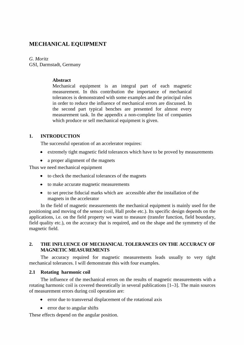
Figure 16 shows a typical CMM bench with three orthogonal axes. All three tables runon linear ball bearings and are driven by stepping or servo motors via lead screws. This stagewas used to map the fringe field region of the dipoles of the APS at ANL c 21d . A similarbench exists at TRIUMF. With an additional auxili ary table, operated in the slave mode, theyoperate the bench as a flip-coil bench.
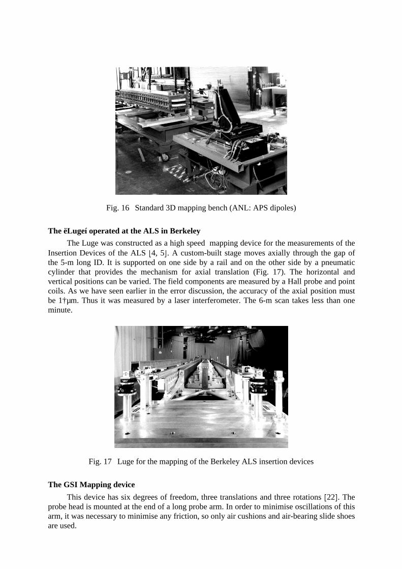
Fig. 16 Standard 3D mapping bench (ANL: APS dipoles)
The ëLugeí operated at the ALS in Berkeley
The Luge was constructed as a high speed mapping device for the measurements of theInsertion Devices of the ALS g 4, 5h . A custom-built stage moves axially through the gap ofthe 5-m long ID. It is supported on one side by a rail and on the other side by a pneumaticcylinder that provides the mechanism for axial translation (Fig. 17). The horizontal andvertical positions can be varied. The field components are measured by a Hall probe and pointcoils. As we have seen earlier in the error discussion, the accuracy of the axial position mustbe 1†µm. Thus it was measured by a laser interferometer. The 6-m scan takes less than oneminute.
Fig. 17 Luge for the mapping of the Berkeley ALS insertion devices
The GSI Mapping device
This device has six degrees of freedom, three translations and three rotations g 22h . Theprobe head is mounted at the end of a long probe arm. In order to minimise oscill ations of thisarm, it was necessary to minimise any friction, so only air cushions and air-bearing slide shoesare used.

The complete system is shown in Figure 18. The three-dimensional measuring machineitself consists of a large granite table on a support sub-frame, two longitudinal slideways forthe x-direction (horizontal), and one each for the y-direction (vertical) and the z-direction(orthogonal), respectively. The mechanical parts are driven on air-bearing shoes by motorsusing a continuous multiple steel band. The linear scan ranges are 2700 mm in the axial (x)and 1000 mm in the transverse (z) and vertical (y) direction. Resolution is 1†µm and 20†µrad.The rotation range around the x-axis is 360•, i 100• around the y-axis and + 30• around the z-axis. The maximum speed is 27 mm/s. The whole machine can be moved either by a crane orair cushions.
Fig. 18 The GSI mapping device
The probe arm consists of three long, carbon-fibre, epoxy cylinders that fit into eachother and are bonded together to a maximum length of 4 m. Three Hall probes are mountedorthogonally to each other in a temperature-stabili sed probe head. The orientation of theprobes can be determined relative to the mirror in front by auto-collimation. The internaldirection cosines of the probe are measured with a precision of 1 part in 10000.
The system was tested in three ways:j Mechanically by electronic level meters: The maximum deviation of the flatness ofthe table was 8†µm, the slideways were straight within 4†µm. The three axes areorthogonal within 0.01†mrad.j Optically by auto-collimation using two mirrors, one attached to the verticalslideway and the other in front of the probe: Moving with a speed of 20 mm/s alongthe x-axis, the maximum angular deviations were 0.01 and 0.08 mrad,respectively—the latter value includes the effect of the vibrations of the long probearm.

k By magnetic measurements in a quadrupole: By averaging over 100 ms the resultswere improved by a factor of 4.
CERN PS magnet mapping bench
The combined-function magnet of the PS (dipole, quadrupole and sextupole!) is mappedin the following way l 23m (Fig. 19): A trolley is driven pneumatically on 6-m long titaniumrails along the longitudinal axis in steps of 20 mm defined by precise notches. The trolleycarries a set of 15 Hall probes, aligned perpendicularly to the longitudinal axis. The lateraldisplacement is n †10†mm. It is used to calculate the gradient. Each time the trolley hasmoved axially the absolute lateral position is checked and corrected by a laser/PSD system toan accuracy of 0.01 mm.
Fig. 19 CERN PS magnet mapping bench
Measur ing benches at LNS
At the LNS (Laboratoire Nationale de Saturne) at Saclay, large benches with modularrails (curved and linear) up to 6-m long were developed. A carriage that is movedpneumatically along these rails can carry up to 100 Hall probes on a transverse 2-m long arm.Thus an area of 12 m2 can be measured in a short time. A special hall probe calibration benchallows 16 encased probes to be calibrated automatically in a reference magnet within 3 hours.
7.1.4 Field direction
The field direction is usually found by mechanical measurements (only for conventionalmagnets) as described above or by the rotating-coil or stretched-wire method alreadydescribed.
7.1.5 Field axis

This is covered in the talk ëFinding the axisí by P. Sievers in these proceedings o 24p .7.1.6 Material
Permeameter/Coercimeter
This topic is covered in the contribution of J. Bill an to these proceedings o 25p .Permanent magnet block measurement (LBL )
For the ALS Insertion Devices the magnetic moment of blocks of permanent magnetshad to be measured o 26p . The following objectives for a Helmholtz coil system wereestablished:q measure the three components of magnetic momentum to an accuracy of r 0.1 %q fast processing: 20 blocks per hour, more than 10000 altogetherq easy to use for an unskill ed operator
This led to the decision to build an automated system. It is shown schematically inFig. 20. The block holder in the centre of the Helmholtz coils attached to a long shaft isrotated 360• by a servomotor. The angle is measured by an encoder. A Fourier analysis of thevoltage induced in the coils gives two components of the magnetic momentum. Then theblock holder is flipped by 90• and rotated again by 360•. This measurement delivers the thirdmomentum component.
OpticalRotaryEncoder
Safety Shield
Block HolderAssembly
Helmholtz Coil
Main DriveAssembly
SupportTable
Fig. 20 Permanent-magnet block measurement (ALS Berkeley)
7.2 Special magnets
7.2.1 Cyclotron magnet mapping

At PSI, Switzerland, and NAC, South Africa special benches for the mapping ofcyclotrons have been built . These are described in the proceedings of the CAS ëMagneticmeasurement and alignmentí course 1992 in Montreux s 20t .
7.2.2 Detector solenoids
Again this topic is covered in the proceedings of the CAS school in Montreux s 27t andin the contribution ëDetector magnet measurementí of D. Newton to these proceedings s 28t .
7.2.3 Electron cooling device (including toroids)
The storage rings LEAR at CERN s 29t and ESR at GSI were fitted with electron coolingdevices. This required mapping of the whole device including the toroids, gun and collectorsolenoids. The solution was to bring the whole device into the horizontal plane. Then thewhole field path was split i n boxes that were measured from various directions (Fig. 21). Thefield components inside the boxes can be evaluated from measurements on the boundariesonly s 30t .
2500 mm
Measuring boxesMeasuring boxes
Fig. 21 Measuring boxes of the GSI ESR electron cooler.
ACKNOWLEDGEMENTS
I thank all my colleagues in the laboratories in Europe and the US for helpfuldiscussions and generously providing information and material.
* * *
REFERENCES
s 1t W.G. Davies, "The theory of the measurement of magnetic multipole fields with rotatingcoil magnetometers", Nucl. Instr. and Meth., A 311, (1992) 399-436.
s 2t L. Walckiers, "The harmonic-coil method", CERN Accelerator School, Montreux,Switzerland, CERN 92-05 (1992) 138-166.
s 3t A. Jain, "Harmonic coils", these proceedings.

u4v S. Marks, C. Cork, E. Hoyer, D. Humphries, B. Kincaid, D. Plate, A. Robb,
R. Schlueter, C. Wang, W. Hassenzahl, "Insertion device magnet measurements for theAdvanced Light Source", 1993 Particle Accelerator Conference, Washington, D.C.,USA (May 1993), 1575-1577.u
5v S. Marks, "Undulator measurements at the ALS", Proceedings of the InternationalMagnet Measurement Workshop (IMMW-9), Vol. II , Saclay, France, 1995.u
6v L.N. Arapov, N.S. Dikanski, V.I. Kokoulin, V.I. Kudelainen, V.A. Lebedev,V.V. Parchomtschuk, B.M. Smirnov, B.N. Suchina, XII I. Int. Conference on HighEnergy Accelerators (1987), 341.u
7v J. Bill an, J.P. Gourber, K.N. Henrichsen, "Geometry and remanent field seriesmeasurements of the LEP dipole magnets", Journal de Physique, C1 (MT-8) (1984),953-956.u
8v H. Br¸ck, R. Meinke, P. Schm¸ser, "Methods for magnetic measurements of thesuperconducting HERA magnets", Kerntechnik, 56 , (1991) 248-256.u
9v D. Zangrando, R.P. Walker, "A stretched-wire system for accurate integrated magneticfield measurements in insertion devices", Nucl. Instr. and Meth., A 376 (1996) 275-282.u
10v R. Wolf, W.C. Li, M.W. Coles, P.F. Pelli ssier, J.E. Dryer, R.Z. Fuzesy, T.R. Gatright,"Magnetic measurement instrumentation developments at the SSC", Supercolli der 4:Proc. of the 4th International Industrial Symposium on the Supercolli der, New Orleans,USA (1992), 467-474.u
11v S.M. Wallas, W.B. Colson, G.R. Neil , L. Harwood, "Magnetic field error measurementof the CEBAF (NIST) wiggler using the pulsed wire method", Nucl. Instr. and Meth.,A 331, (1993) 759-762.u
12v B.C. Brown, "Fundamentals of magnetic measurements with ill ustrations from Fermilabexperience", Proc. of the ICFA Workshop on Superconducting Magnets and Cryogenics,Brookhaven National Lab., Upton, USA (May 1986) 297-301.u
13v R. Chritin, D. Cornuet, G. Patron, E. Scarset, G. Patron, E. Scarset "Mesure magnÈtiquedes quadrupÙles CLIC types I et II ", CERN Note technique SL note 96-74 (MS).u
14v G. Moritz, F. Klos, B. Langenbeck, Q. Youlun, K. Zweig, "Measurements of the SISmagnets", IEEE Trans. on Magnetics, vol. 24, no. 2 (MT-10) (1988) 942-945.u
15v S.H. Kim, C. Doose, R. Hogrefe, K. Kim, R. Merl, "The Magnet Measurement Facilit yfor the Advanced Photon Source", IEEE Trans. on Magnetics, vol. 30, no. 4 (MT-13)(1994) 2616-2619.u
16v O. Pagano, P. Rohmig, L. Walckiers, C. Wyss, "A highly automated measuring systemfor the LEP magnetic lenses", Journal de Physique, C1 (MT-8) (1984) 949-952.u
17v G. Ganetis, et al., "Field Measuring Probe for SSC Magnets", Proc. 1987 ParticleAccelerator Conference, Washington, DC, (1987).

w18x R. Thomas, et al., "Performance of Field Measuring Probes for SSC Magnets", Proc. 5th
Annual International Symposium on Super Colli der (IISSC), San Francisco, Cali fornia,May 6-8, (1993).w
19x J. Bill an, S. De Panfili s, D. Giloteaux, O. Pagano, "Ambient temperature field measuringsystem for LHC superconducting dipoles", IEEE Trans. on Magnetics, vol. 32, no. 4(MT-14) (1996) 3073-3076.w
20x A. Harvey, "Mechanical equipment for magnet measurement and alignment", CERNAccelerator School, Montreux, Switzerland, CERN 92-05 (1992) 228-239.w
21x S.H. Kim, K. Kim, C. Doose, R. Hogrefe, R. Merl, "Magnetic measurements of thestorage ring quadrupole magnets for the 7-GeV Advanced Photon Source", 1993 ParticleAccelerator Conference, Washington, D.C., USA (May 1993) 2805-2807.w
22x G. Moritz, H. Gaiser, F. Klos, B. Langenbeck, R. Steiner, K. Zweig, "Design,Performance and Applications of the GSI Three-Dimensional Magnet MeasuringDevice", IEEE Trans. on Magnetics, vol. 30, no. 4 (MT-13) (1994) 2650-2653.w
23x D. Cornuet, Z. Sharifulli n; CERN Technical Note, AT/MA Note 92-23.w24x P. Sievers, R. Thomas, et al., "Finding the axis", these proceedings.w25x J. Bill an, "Materials", these proceedings.w26x S. Marks, J. Carrieri, C. Cook, W.V. Hassenzahl, E. Hoyer, D. Plate, "ALS Insertion
Device Block Measurement and Inspection", 1991 Particle Accelerator Conference, SanFrancisco, USA (May 1991).w
27x D. Newton, "The magnetic field mapping of detector magnets", CERN AcceleratorSchool, Montreux, Switzerland, CERN 92-05 (1992) 283-295.w
28x D. Newton, "Detector magnet measurement", these proceedings.w29x A. Wolf, L. H¸tten, H. Poth, "Magnetic Field Measurements in the Electron Cooling
Device for LEAR", CERN, EP Internal Report 84-01 (1984).w30x H. Wind, "Evaluating a magnetic field component from boundary observation only",
Nuclear Instruments and Methods 84 (1970), 117-124

APPENDIX 1
Mechanical/Optical Components
Component Specifications/Features Companies
Linear-,RotationTable/Stages/OpticalComponents
For example: Micro controle MT160Resolution : 0.1µmReproducibilit y: 0.1µmAccuracy: 1µm (for 100mm travel
length)Max. speed: 40 mm/s
Micro Controle/Newport,FranceKlinger Scientific Corp., U.S.A.Spindler & Hoyer, GermanyBurleigh Instruments Inc., U.S.A.SKF, Germany
Linear encoder Best accuracy of the system: 0.1µmTemp. coeff .: 0/•K (substrate: glass
ceramics) to 10 ppm/•K (glass)
Heidenhain, Germany
Rotaryencoder(incremental)
Line counts up to 10000/revolutionInterpolation by factor 4 and 5Accuracy: 0.05 mrad
Heidenhain, GermanyGurley Precision Instruments,U.S.A.BEI, Encoder System Division,U.S.A.Litton Precision Products, GermanyBaumer Electric AG, SwitzerlandCODECHAMP, France
Interferometer Resolution: up to 1nm U.S.A. Hewlett-Packard, U.S.A.Zygo Corp., U.S.A.Teletrac Inc., U.S.A.Spindler & Hoyer, Germany
Capaciti vesensor
Position accuracy (x-y): 1µm FOGALE nanotech, FranceCapacitec, U.S.A.
Air-motor Zo-Air Co.,U.S.A.Physik Instrument, PI CeramicGmbH , GermanyShinsei, Japan
Piezo-Electricmotor
MicroPulse Systems, Inc, U.S.A.
Step,microstepmotor
Microstep: up to 50000 steps/rev. Parker Hannifin Corporation,Compumotor Division, U.S.A.Micro Controle/Newport, FranceBerger GmbH, GermanyFENWICK, France
Servo-motor Micro Controle/Newport, FranceMaxon motor Interelectric,SwitzerlandMaxon Precision Motors, Inc,U.S.A.Minimotor SA, SwitzerlandPortescap, SwitzerlandPortescap U.S., Inc., U.S.A.

Component Specifications/Features CompaniesBall bearings(steel)
Centre-position stabilit y: 1–2µm FAG, Germany
Ball bearings(ceramicglass)
Centre-position stabilit y: some µm Wemhˆner&Popp, GermanyKoba Electronics, Japan
Slip rings Schleifring, GermanyLitton Precision Products, Germany
Inclinometer Principle: capaciti ve position measure-ment of a pendulum
Accuracy: 0.04 mradResolution: 0.002 mrad
Wyler, SwitzerlandSchaevitz, c/o Althen Messtechnik, Germany
Gravity sensor/Tilt sensor
Principle: resistance measurement of an electrolytic liquid
in a vialRange: y 1•, nearly-zero methodResolution: 1 µradTemp. coeff icient <2µrad/•CTemp. compensated
Spectron / G+G Technics AG,Switzerland
Laser foralignment
For mounting in a spindle0.01 mm beam centre position0.002mm/hr/•C centering stabilit y.
Hamar Laser Instruments, U.S.A.OPTILAS, FranceGerhard Franck Optronic, Germany
Positionsensiti vedetector/diode
United Detector Technology, U.S.A.Yamamatsu, Japan
Four-axistarget
Two-axis centering: 0.01 mmSquareness (pitch/yaw): 0.04mm/m
Hamar Laser Instruments
Auto-collimator
Resolution: 0.1µradRange: y 2mrad
Micro Controle/Newport, FranceRank Taylor-Hobson, UKSpindler & Hoyer, Germany
Torquemeter/strain gauge
Kistler, SwitzerlandApplied Geomechanics Inc.,U.S.A.