mechanicalandstructuralpropertiesof fluorine-ion
TRANSCRIPT
Hindawi Publishing CorporationAdvances in Materials Science and EngineeringVolume 2012, Article ID 792973, 11 pagesdoi:10.1155/2012/792973
Research Article
Mechanical and Structural Properties ofFluorine-Ion-Implanted Boron Suboxide
Ronald Machaka,1, 2 Bonex W. Mwakikunga,3, 4 Elayaperumal Manikandan,3, 5
Trevor E. Derry,1, 6 Iakovos Sigalas,1, 2 and Mathias Herrmann7
1 DST/NRF Centre of Excellence in Strong Materials, University of the Witwatersrand, Private Bag 3, Wits,Johannesburg 2050, South Africa
2 School of Chemical and Metallurgical Engineering, University of the Witwatersrand, Private Bag 3, Wits,Johannesburg 2050, South Africa
3 National Centre for Nano-Structured Materials, CSIR, P.O. Box 395, Pretoria 0001, South Africa4 Department of Physics and Biochemical Sciences, University of Malawi, The Polytechnic, Private Bag 303, Chichiri,Blantyre 0003, Malawi
5 Nano Centre, Polymer Nanotechnology Center & Department of Physics, B. S. Abdur Rahman University,Vandalur, Chennai-600048, India
6 School of Physics, University of the Witwatersrand, Private Bag 3, Wits, Johannesburg 2050, South Africa7 Fraunhofer Institute for Ceramic Technologies and Systems, Winterbergstraße 28, 01277 Dresden, Germany
Correspondence should be addressed to Ronald Machaka, [email protected]
Received 30 April 2011; Revised 18 September 2011; Accepted 19 September 2011
Academic Editor: W. Ensinger
Copyright © 2012 Ronald Machaka et al. This is an open access article distributed under the Creative Commons AttributionLicense, which permits unrestricted use, distribution, and reproduction in any medium, provided the original work is properlycited.
Results on a systematic study on the effects of ion implantation on the near-surface mechanical and structural properties of boronsuboxide (B6O) prepared by uniaxial hot pressing are reviewed. 150 keV fluorine ions at fluences of up to 5.0 × 10¹⁶ ions/cm2
were implanted into the ultrahard ceramic material at room temperature and characterized using Raman spectroscopy, atomicforce microscopy, and scanning electron microscopy with energy-dispersive X-ray spectroscopy. Evidence of ion-beam-assistednucleation of novel clustered BxOyFz particles by ion implantation is revealed. In addition, obtained results also reveal that fluorineimplantation into the B6O specimen leads to an overall degradation of near-surface mechanical properties with increasing fluorinefluence. Implications of these observations in the creation of amorphous near-surface layers by high-dose ion implantation arediscussed in this paper.
1. Introduction
Energetic ions have been of interest to researchers fortheir capability of (i) characterization of materials, (ii)modification of materials, and more recently (iii) synthesisof new materials. Of particular interest is the possibility ofion beams to circumvent thermodynamic limits related toconventional methods such as diffusion, solubility, deposi-tion, and alloy formation by providing high kinetic energythrough ion impact and utilizing ballistic effects during ion-solid interaction [1–4]. Moreover, ion implantation allowsthe precise control of the ion energy, ion fluence, dopantdistribution as well as a choice of the ion species. As
a result the surface modification conditions can also beinfluenced with a great deal of reproducibility and controlfor specific needs, that is, either synthesis, modification, orcharacterization of materials.
The increasing fascination with low-dimensional mate-rial structures is mainly motivated by the search for newmaterials with tunable novel properties of evident techno-logical relevance. It is therefore not surprising that nanos-tructured materials are gaining growing importance due totheir unique properties that are intermediate between thosecorresponding to the bulk solids and molecules. In recentyears many groups have reported on the ion-beam-assisted
2 Advances in Materials Science and Engineering
synthesis of novel nanostructured materials by ion implanta-tion [3, 5–7]. In addition, unique and sometimes superiormechanical [1, 8], structural [2, 9–11], optoelectronic [7,12], corrosion, and tribomechanical surface properties [2,13] of the ion-implanted materials have also been reported.
Boron suboxide, B6O, is an superhard boron-richceramic material. It exhibits a rather unusual and wide rangeof superior properties; among these are high hardness withlow density, high mechanical strength, oxidation resistanceup to high temperatures as well as its chemical inertness[14–18]. The potential applications of B6O as ideal wear-reduction coatings for high-speed cutting tools, abrasives,or other high-wear applications, for example, have been anobject of intense interest in recent years [19, 20]. How-ever, despite the intensive research efforts, the commercialapplications are yet to be realized. This is partly becauseof the low fracture toughness of hot-pressed materials [17,18] and the considerable practical challenges associatedwith the densifying stoichiometric B6O material with goodcrystallinity [17, 18]. Furthermore, numerous mechanicalproperties of the material were until recently rather poorlyunderstood [14, 21].
Preliminary first-principle ab initio density functionalcalculations of the structural properties of boron suboxide(nominally B6O) by Lowther suggest that the strength of thebonding in B6O (and other boron-rich superhard materialssuch as B4C and AlMgB14) may be enhanced by the presenceof a high electronegativity interstitial in the structure [22].The computational calculations confirm the shortening ofcovalent bonds which is believed to favour higher elastic con-stants and hardness values. By introducing energetic fluorineions into B6O using ion implantation—a nonequilibriumtechnique of choice for introducing “controlled” defects intothe near-surface layers [4, 23]. To the best of our knowledge,no work has been reported on effect of ion implantationon the near-surface mechanical and structural properties ofB6O.
In our work, the radiation effects of the ceramic materialunder heavy ion irradiation have been studied to developan understanding of the radiation resistance evolutionwith respect to the material properties. We apply nanoin-dentation, Raman spectroscopy, atomic force microscopy(AFM), and scanning electron microscopy (SEM) withenergy-dispersive X-ray spectroscopy (EDX) to demonstratethe synthesis of BxOyFz clustered particles using 150 keVfluorine ion implantation into B6O. This paper reviewsresults obtained in the study.
2. Experimental Methods
B6O powder synthesized at the Fraunhofer Institute forCeramic Technologies and Systems, Dresden, Germany, byreacting B and B2O3 as detailed by Andrews et al. in [18]was prepared and uniaxially hot-pressed in hBN pots underargon environment at 1800◦C and 50 MPa for 20 min at theSchool of Chemical and Metallurgical Engineering, Univer-sity of the Witwatersrand, Johannesburg, South Africa. Thehot-pressed compacts were then prepared using a method
Table 1: The nomenclature of the unimplanted and implantedsamples.
Sample no. Ion speciesEnergy Fluence
keV F+/cm2
A — — —
B F+ 150 1.0× 10¹⁴
C F+ 150 5.0× 10¹⁴
D F+ 150 5.0× 10¹⁵
E F+ 150 1.0× 10¹⁶
F F+ 150 3.0× 10¹⁶
G F+ 150 5.0× 10¹⁶
prescribed by Machaka et al. in [21]. The density of the hot-pressed compacts measured 2.44 g/cm3.
150 keV fluorine ions were implanted into hot-pressedB6O specimen at fluences between 1.0 × 10¹⁴ to 5.0 ×10¹⁶ ions/cm2 at room temperature. A modified Varian-Extrion 200-20A2F model ion implanter at iThemba LABS(Gauteng), Johannesburg was used. The nomenclature ofthe unimplanted and implanted samples is tabulated inTable 1. The depth distribution of the radiation damage andimplanted ion profile were estimated using SRIM2010 [24],a suite of Monte Carlo computational codes popular forthe simulation of the interactions of energetic ions with thetarget material.
The specimen’s surface microstructure and compositionwere characterized by SEM and EDX, respectively. Thespecimen surface topography was characterized using AFM.Gwyddion v2.24 [25], a modular multiplatform software forprofilometric data analysis, was used to analyze AFM images.The powder diffraction patterns were collected using a CuKα source in the Bragg-Brentano backscattering geometryover a 10◦–90◦ 2θ range, with a 0.02◦ step size. Ramanmeasurements performed at the CSIR’s National Centrefor nanostructured materials nanomaterial characterizationfacility under ambient conditions using a 514.5 nm Ar+ ionexcitation were used to characterize the ion beam inducedstructural modifications whilst the mechanical properties ofthe unimplanted and implanted samples were determinedusing nanoindentation at Nelson Mandela MetropolitanUniversity, Port Elizabeth. Details of the experimental pro-cedures of the Raman spectroscopy and the nanoindentationmeasurements are also reported elsewhere [14, 26].
3. Results and Discussions
3.1. Structural Characterization
3.1.1. Implant Depth Profile. The distribution of the im-planted fluorine ions estimated using SRIM2010 can bedescribed as a near-Gaussian shape function characterizedwith a projected range of about 450 nm and an estimatedrange straggling of about 60 nm. However, in practice weare aware that the SRIM estimation does not take intoaccount the possible surface sputtering, dynamic annealing,and diffusion processes taking place during ion implantation.
Advances in Materials Science and Engineering 3
Acc. V Det WD 5 µm512 kV 5000x CL 11.9 B6OSpot Magn
(a)
0 1 2 3 4 5 6 7 80
0.3
0.6
0.9
1.3
1.6
KC
nt
Energy (keV)
B
O
Fe Fe
(b)
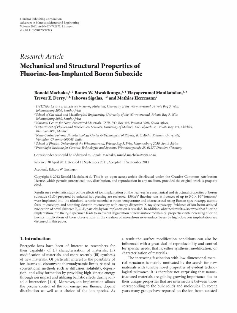
Figure 1: It shows the SEM surface micrograph (a) and theEDX surface compositional analysis (b) of the hot-pressed B6Ospecimen. Iron contamination (bright spots on SEM micrograph)is responsible for EDX elemental peaks observed.
3.1.2. SEM and EDX Analysis. The surface morphology andcompositional analysis of unimplanted B6O specimen asdetermined by SEM and EDX are shown in Figures 1(a) and1(b), respectively. By and large, the SEM micrograph showsa homogeneous B6O microstructure with visible pores onthe specimen surface as a direct result of some considerablepractical challenges in the densification of B6O by hotpressing [15–17].
The analysis of the surface composition by EDX isalso indicative of nominally pure B6O phase. The observediron contamination (typically a few wt.%) is expected andunavoidable possibly as a direct consequence of the abrasionof the steel ball and the containment cell during powder ballmilling [19, 20, 27].
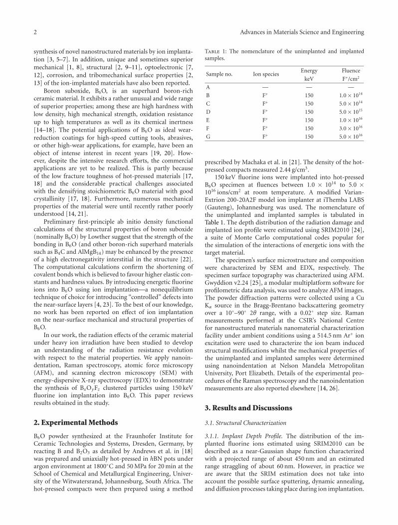
The SEM and EDX analysis of the heavily implantedspecimen (B4 in Figures 2(b)–2(d)), for example, showsobvious dissimilarities between the unimplanted and theimplanted specimen. Firstly, in addition to the homogeneousB6O phase the surface pores and the iron and chromiumcontamination, SEM micrographs show evidence of the
existence of additional clusters of ion-beam-synthesizedparticles. Secondly, image analysis of the microstructure(Figures 2(b) and 2(c)) indicates that the average particlesizes of the formed clusters is 110 nm. Thirdly, the measuredEDX pattern shows two weak iron peaks at 0.75 ev and6.4 eV. Although the positions of the 0.75 eV iron peak andthe fluorine peak coincide, there appears to exist enoughevidence observed to indicate a BxOyFz stoichiometry forthe ion-beam-synthesized clustered particles. We have alsoobserved that the compositional change becomes more sig-nificant with increasing fluorine implantation dose. The B6Osignature EDX pattern unimplanted specimen is depicted inFigure 1(b) [15, 28].
3.1.3. Raman Spectroscopy Analysis. Raman scattering spec-troscopy is very sensitive to the nature of crystalline struc-ture, disorder, and amorphization and is often employedto characterize ion-implantation-induced defects and anyirregularity in the crystalline symmetry. The rather populartechnique offers a rapid, nondestructive, and simple diagnos-tic probe for the evaluation of the structural modificationsimposed by ion implantation and for optical characterizationof ion-implanted specimens since the penetration depthof the laser beam is often of the order of the depth ofpenetration of implanted ions.
Figures 3 and 4 show the Raman spectra of pristine(specimen A) and F+-implanted hot-pressed B6O (specimensB to G). The Raman spectrum of the pristine specimen ischaracteristic of nominal composition B6O [21, 29–32].
The measured Raman spectra are evidently characterizedby a relatively low Raman signal to noise ratio. Nevertheless,it is not difficult to see that F+ implantation at fluences upto 5.0× 10¹⁵ ions/cm2 reveals that the material resists amor-phization and retains the crystal structure of B6O. At thesame time, implantation at fluences above 5.0×10¹⁵ ions/cm2
clearly shows that the signature Raman spectrum of B6Opredominately disappears (specimen D).
Rao et al. [33, 34], in Raman scattering spectroscopy,the main effect in going from the crystalline to amorphousform is the introduction of characteristic features in thefrequencies and line shapes of the Raman modes. However,for a diatomic lattice, the effect of amorphization shouldbe a decrease in intensity of the lattice modes and even thedisappearance of these modes at higher ion implantationdoses. Accordingly, we tentatively attribute the disappearanceof the signature B6O Raman spectrum at implantationfluences exceeding 5.0 × 10¹⁵ ions/cm2 to amorphization asa result of ion-induced radiation damage.
Measured spectra on samples implanted at fluencesbeyond 5.0 × 10¹⁵ ions/cm2 reveal an almost unrelatedand new asymmetrically broadened Raman feature centredaround 1550 cm−1. In general, it is widely accepted in thefield that the observed line shape asymmetry is consistentwith the size-dependent effects in measured Raman modes—optical phonon confinement [35]. The existence of ion-beam-synthesized aggregates made up of micro- and/ornanosized particles is known to exhibit this phenomenon.For example, we recently reported on the Raman spectraof cBN nanocrystals formed by He+ ion implantation into
4 Advances in Materials Science and Engineering
Acc. V Det WD2000x CL
10 µm512 kV 11.9Spot Magn
B6O
(a)
1 µmAcc. V Det WD20000x SE515 kV 12.6
Spot MagnB6O-B4
(b)
Acc. V Det WD 500 nm40000x SE 12.6515 kV
Spot MagnB6O-B4
(c)
0 1 2 3 4 5 6 70
0.2
0.5
0.7
1
1.2
KC
nt
Energy (keV)
B
O
Fe
FeCr
F
(d)
Figure 2: A depiction of SEM images measured on the surface of (a) an unimplanted B6O specimen, ((b) and (c)) a 5.0× 10¹⁵ F+ ions/cm2
implanted B6O specimen showing clusters of particles embedded in the samples synthesized by fluorine-ion-beam implantation, and (d) anEDX measured pattern on one such ion-beam-synthesized cluster which is highlighted in micrograph (c).
hBN [9]. Several other researchers have also reported on theion-beam synthesis of other nanostructures phased by ionbombardment [3, 5, 6]. In fact, ion implantation is a methodof choice for synthesizing nc-Si in optoelectronics [7].
A further increase in the implantation fluence beyond5.0 × 1015 ions/cm2 gives rise to further increase in bothwidth and intensity of the asymmetrically broadened Ramanfeature. Furthermore, increases in the feature’s peak intensitywith increasing ion dose may be a result of the increase involume fraction of the clustered particles in the materialsurface layer. A critical fluence of about 3.0 × 10¹⁶ ions/cm2
was observed beyond which the volume fraction of theclustered particles will reduce owing to the existence ofsurface sputtering and possibly radiation damage.
In summary, a possible explanation of this Ramanscattering characteristic in ion-implanted B6O could be thenucleation of a new micro- or nanocrystalline phase in theB6O matrix. At higher doses, ion implantation creates anonequilibrium solid-state supersaturation of the implantedions in solutions which could induce the precipitation of ion-beam-synthesized nanostructured particle nuclei effectively,
due to thermodynamic stabilization. These nuclei grow addi-tionally as a result of the surface deposition of solvated ions.According to Shen et al. [8], the ion beam synthesis of thenanostructured particles could be conceptualized into severalsteps: (i) stopping and accumulation of F implants in thenear-surface area of the host B6O matrix, (ii) supersaturationof this area by F implants, (iii) formation of nuclei of aBxOyFz phase, and (iv) growth of the nanoparticles fromthe nuclei. Stepanov in reference [3] best illustrates the basicphysical processes involved in the formation of nanoparticlesfrom an implant with respect to the ion dose in Figure 5shown below.
3.2. Mechanical Characterization. The representative inden-tation load-displacement (P-h) curves continuously mea-sured during loading and unloading for the four specimensunder investigation (unimplanted (specimen A) and fluorineimplanted (specimens C, D, and G)) are shown in Figure 6.The intrinsic hardness H(E) and the elastic modulus E ofspecimen were evaluated from the nanoindentation responsecurves by applying a modified O&P procedure as outlined in
Advances in Materials Science and Engineering 5
First-order R.S. Higher-order R.S.
500 1000 1500 2000 2500
Raman shift (cm−1)
Ram
anin
ten
sity
(a.u
.)
Incr
easi
ng
F+io
ndo
se
A
B
C
D
E
F
G
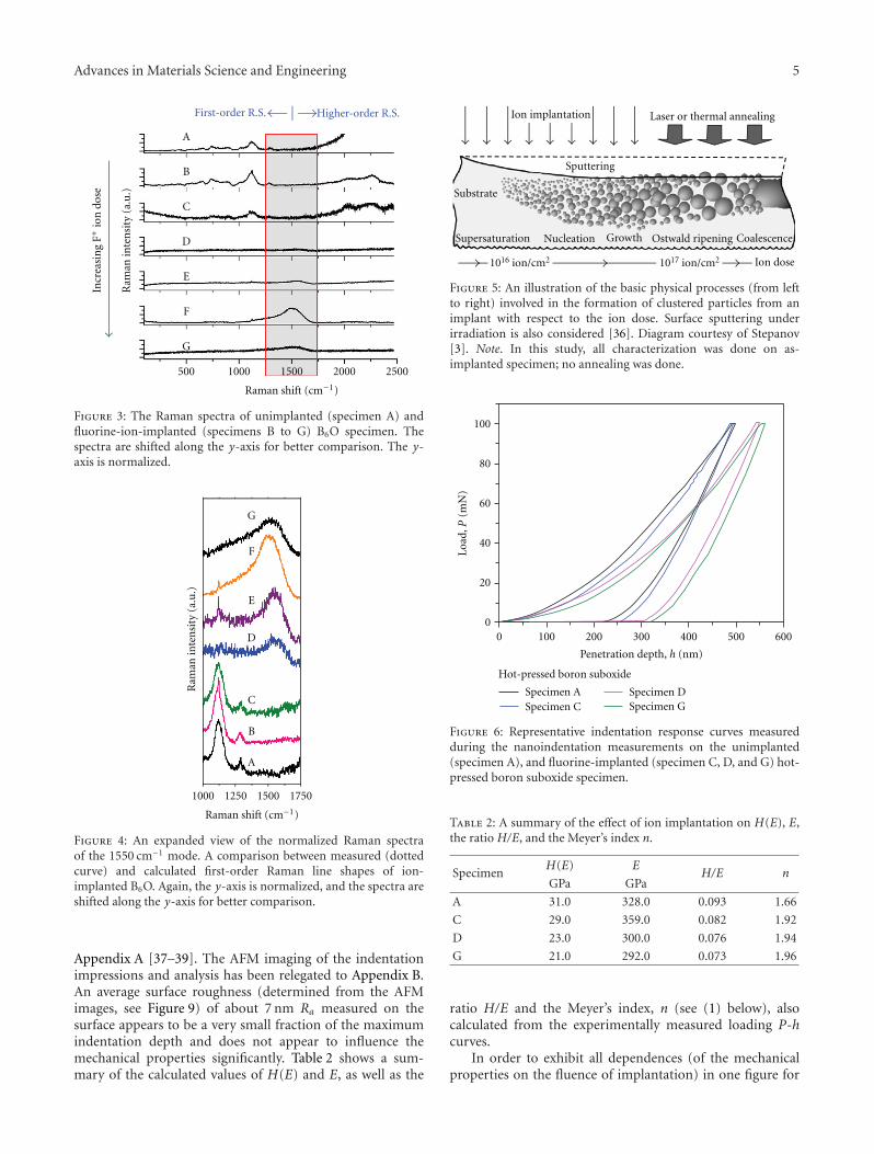
Figure 3: The Raman spectra of unimplanted (specimen A) andfluorine-ion-implanted (specimens B to G) B6O specimen. Thespectra are shifted along the y-axis for better comparison. The y-axis is normalized.
1000 1250 1500 1750
Raman shift (cm−1)
Ram
anin
ten
sity
(a.u
.)
A
B
C
D
E
F
G
Figure 4: An expanded view of the normalized Raman spectraof the 1550 cm−1 mode. A comparison between measured (dottedcurve) and calculated first-order Raman line shapes of ion-implanted B6O. Again, the y-axis is normalized, and the spectra areshifted along the y-axis for better comparison.
Appendix A [37–39]. The AFM imaging of the indentationimpressions and analysis has been relegated to Appendix B.An average surface roughness (determined from the AFMimages, see Figure 9) of about 7 nm Ra measured on thesurface appears to be a very small fraction of the maximumindentation depth and does not appear to influence themechanical properties significantly. Table 2 shows a sum-mary of the calculated values of H(E) and E, as well as the
1016 ion/cm2 1017 ion/cm2 Ion dose
Ion implantation Laser or thermal annealing
Sputtering
Substrate
Supersaturation Nucleation Growth Ostwald ripening Coalescence
Figure 5: An illustration of the basic physical processes (from leftto right) involved in the formation of clustered particles from animplant with respect to the ion dose. Surface sputtering underirradiation is also considered [36]. Diagram courtesy of Stepanov[3]. Note. In this study, all characterization was done on as-implanted specimen; no annealing was done.
Specimen ASpecimen C
Specimen DSpecimen G
0 100 200 300 400 500 600
Penetration depth, h (nm)
0
20
40
60
80
100
Load
,P(m
N)
Hot-pressed boron suboxide
Figure 6: Representative indentation response curves measuredduring the nanoindentation measurements on the unimplanted(specimen A), and fluorine-implanted (specimen C, D, and G) hot-pressed boron suboxide specimen.
Table 2: A summary of the effect of ion implantation on H(E), E,the ratio H/E, and the Meyer’s index n.
SpecimenH(E) E
H/E nGPa GPa
A 31.0 328.0 0.093 1.66
C 29.0 359.0 0.082 1.92
D 23.0 300.0 0.076 1.94
G 21.0 292.0 0.073 1.96
ratio H/E and the Meyer’s index, n (see (1) below), alsocalculated from the experimentally measured loading P-hcurves.
In order to exhibit all dependences (of the mechanicalproperties on the fluence of implantation) in one figure for
6 Advances in Materials Science and Engineering
0 25 50 425 450 475 500
0.7
0.8
0.9
1
Hardness, H(E)
Nor
mal
ized
har
dnes
s
Fluence (×1014 F+/cm2)
(a) Intrinsic hardness
0 25 50 425 450 475 500
0.9
1
1.1
Elastic modulus, E
Ela
stic
mod
ulu
s
Fluence (×1014 F+/cm2)
(b) Elastic modulus
0 25 50 425 450 475 500
0.8
0.9
1
H/E ratio
H/E
rati
o
Fluence (×1014 F+/cm2)
(c) H/E ratio
0 25 50 425 450 475 5001.6
1.7
1.8
1.9
2
Mey
er s
inde
x
Meyers index, n
Fluence (×1014 F+/cm2)
(d) The Meyer’s index measured for hot-pressed B6O samples irradi-ated with various fluences of F ions
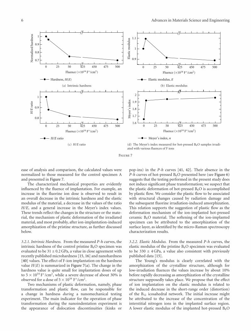
Figure 7
ease of analysis and comparison, the calculated values werenormalized to those measured for the control specimen Aand presented in Figure 7.
The characterized mechanical properties are evidentlyinfluenced by the fluence of implantation. For example, anincrease in the fluorine ion dose is observed to result inan overall decrease in the intrinsic hardness and the elasticmodulus of the material, a decrease in the values of the ratioH/E, and a general increase in the Meyer’s index values.These trends reflect the changes in the structure or the mate-rial, the mechanism of plastic deformation of the irradiatedmaterial, and most probably, after ion-implantation-inducedamorphization of the pristine structure, as further discussedbelow.
3.2.1. Intrinsic Hardness. From the measured P-h curves, theintrinsic hardness of the control pristine B6O specimen wasevaluated to be 31± 0.2 GPa, a value in close agreement withrecently published microhardness [15, 16] and nanohardness[40] values. The effect of F-ion implantation on the hardnessvalue H(E) is summarized in Figure 7(a). The change in thehardness value is quite small for implantation doses of upto 5 × 10¹⁴ F+/cm2, while a severe decrease of about 30% isobserved for a dose of 5× 10¹⁶ F+/cm2.
Two mechanisms of plastic deformation, namely, phasetransformation and plastic flow, can be responsible fora change in hardness during a nanomechanical testingexperiment. The main indicator for the operation of phasetransformation during the nanoindentation experiment isthe appearance of dislocation discontinuities (kinks or
pop-ins) in the P-h curves [41, 42]. Their absence in theP-h curves of hot-pressed B6O presented here (see Figure 6)suggests that the testing performed in the present study doesnot induce significant phase transformation; we suspect thatthe plastic deformation of hot-pressed B6O is accomplishedby plastic flow. We consider the plastic flow to be associatedwith structural changes caused by radiation damage andthe subsequent fluorine irradiation-induced amorphization.This relation supports the suggestion of plastic flow as thedeformation mechanism of the ion-implanted hot-pressedceramic B6O material. The softening of the ion-implantedspecimen can be attributed to the amorphization of thesurface layer, as identified by the micro-Raman spectroscopycharacterization results.
3.2.2. Elastic Modulus. From the measured P-h curves, theelastic modulus of the pristine B6O specimen was evaluatedto be 330 ± 4 GPa, a value also consistent with previouslypublished data [15].
The Young’s modulus is clearly correlated with theamorphization of the crystalline structure, although forlow-irradiation fluences the values increase by about 10%before rapidly decreasing as amorphization of the crystallinestructure supposedly takes place. We propose that the effectof ion implantation on the elastic modulus is related tothe induced decrease in the short-range order (distortion)of the B12 icosahedral network. The initial increase mightbe attributed to the increase of the concentration of theinterstitial nitrogen ions in the implanted surface region.A lower elastic modulus of the implanted hot-pressed B6O
Advances in Materials Science and Engineering 7
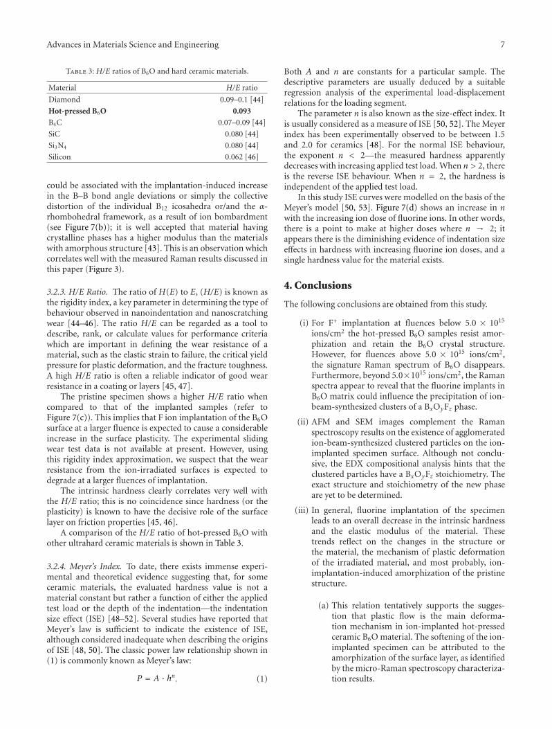
Table 3: H/E ratios of B6O and hard ceramic materials.
Material H/E ratio
Diamond 0.09–0.1 [44]
Hot-pressed B6O 0.093
B4C 0.07–0.09 [44]
SiC 0.080 [44]
Si3N4 0.080 [44]
Silicon 0.062 [46]
could be associated with the implantation-induced increasein the B–B bond angle deviations or simply the collectivedistortion of the individual B12 icosahedra or/and the α-rhombohedral framework, as a result of ion bombardment(see Figure 7(b)); it is well accepted that material havingcrystalline phases has a higher modulus than the materialswith amorphous structure [43]. This is an observation whichcorrelates well with the measured Raman results discussed inthis paper (Figure 3).
3.2.3. H/E Ratio. The ratio of H(E) to E, (H/E) is known asthe rigidity index, a key parameter in determining the type ofbehaviour observed in nanoindentation and nanoscratchingwear [44–46]. The ratio H/E can be regarded as a tool todescribe, rank, or calculate values for performance criteriawhich are important in defining the wear resistance of amaterial, such as the elastic strain to failure, the critical yieldpressure for plastic deformation, and the fracture toughness.A high H/E ratio is often a reliable indicator of good wearresistance in a coating or layers [45, 47].
The pristine specimen shows a higher H/E ratio whencompared to that of the implanted samples (refer toFigure 7(c)). This implies that F ion implantation of the B6Osurface at a larger fluence is expected to cause a considerableincrease in the surface plasticity. The experimental slidingwear test data is not available at present. However, usingthis rigidity index approximation, we suspect that the wearresistance from the ion-irradiated surfaces is expected todegrade at a larger fluences of implantation.
The intrinsic hardness clearly correlates very well withthe H/E ratio; this is no coincidence since hardness (or theplasticity) is known to have the decisive role of the surfacelayer on friction properties [45, 46].
A comparison of the H/E ratio of hot-pressed B6O withother ultrahard ceramic materials is shown in Table 3.
3.2.4. Meyer’s Index. To date, there exists immense experi-mental and theoretical evidence suggesting that, for someceramic materials, the evaluated hardness value is not amaterial constant but rather a function of either the appliedtest load or the depth of the indentation—the indentationsize effect (ISE) [48–52]. Several studies have reported thatMeyer’s law is sufficient to indicate the existence of ISE,although considered inadequate when describing the originsof ISE [48, 50]. The classic power law relationship shown in(1) is commonly known as Meyer’s law:
P = A · hn. (1)
Both A and n are constants for a particular sample. Thedescriptive parameters are usually deduced by a suitableregression analysis of the experimental load-displacementrelations for the loading segment.
The parameter n is also known as the size-effect index. Itis usually considered as a measure of ISE [50, 52]. The Meyerindex has been experimentally observed to be between 1.5and 2.0 for ceramics [48]. For the normal ISE behaviour,the exponent n < 2—the measured hardness apparentlydecreases with increasing applied test load. When n > 2, thereis the reverse ISE behaviour. When n = 2, the hardness isindependent of the applied test load.
In this study ISE curves were modelled on the basis of theMeyer’s model [50, 53]. Figure 7(d) shows an increase in nwith the increasing ion dose of fluorine ions. In other words,there is a point to make at higher doses where n → 2; itappears there is the diminishing evidence of indentation sizeeffects in hardness with increasing fluorine ion doses, and asingle hardness value for the material exists.
4. Conclusions
The following conclusions are obtained from this study.
(i) For F+ implantation at fluences below 5.0 × 10¹⁵
ions/cm2 the hot-pressed B6O samples resist amor-phization and retain the B6O crystal structure.However, for fluences above 5.0 × 10¹⁵ ions/cm2,the signature Raman spectrum of B6O disappears.Furthermore, beyond 5.0×10¹⁵ ions/cm2, the Ramanspectra appear to reveal that the fluorine implants inB6O matrix could influence the precipitation of ion-beam-synthesized clusters of a BxOyFz phase.
(ii) AFM and SEM images complement the Ramanspectroscopy results on the existence of agglomeratedion-beam-synthesized clustered particles on the ion-implanted specimen surface. Although not conclu-sive, the EDX compositional analysis hints that theclustered particles have a BxOyFz stoichiometry. Theexact structure and stoichiometry of the new phaseare yet to be determined.
(iii) In general, fluorine implantation of the specimenleads to an overall decrease in the intrinsic hardnessand the elastic modulus of the material. Thesetrends reflect on the changes in the structure orthe material, the mechanism of plastic deformationof the irradiated material, and most probably, ion-implantation-induced amorphization of the pristinestructure.
(a) This relation tentatively supports the sugges-tion that plastic flow is the main deforma-tion mechanism in ion-implanted hot-pressedceramic B6O material. The softening of the ion-implanted specimen can be attributed to theamorphization of the surface layer, as identifiedby the micro-Raman spectroscopy characteriza-tion results.
8 Advances in Materials Science and Engineering
(iv) The decrease in both the H/E ratio and the Meyer’sindex with ion dose might imply that F ion implan-tation of the B6O surface at a larger fluence isexpected to cause a considerable increase in thesurface plasticity.
Appendices
A. Oliver and Pharr Analysis Approach
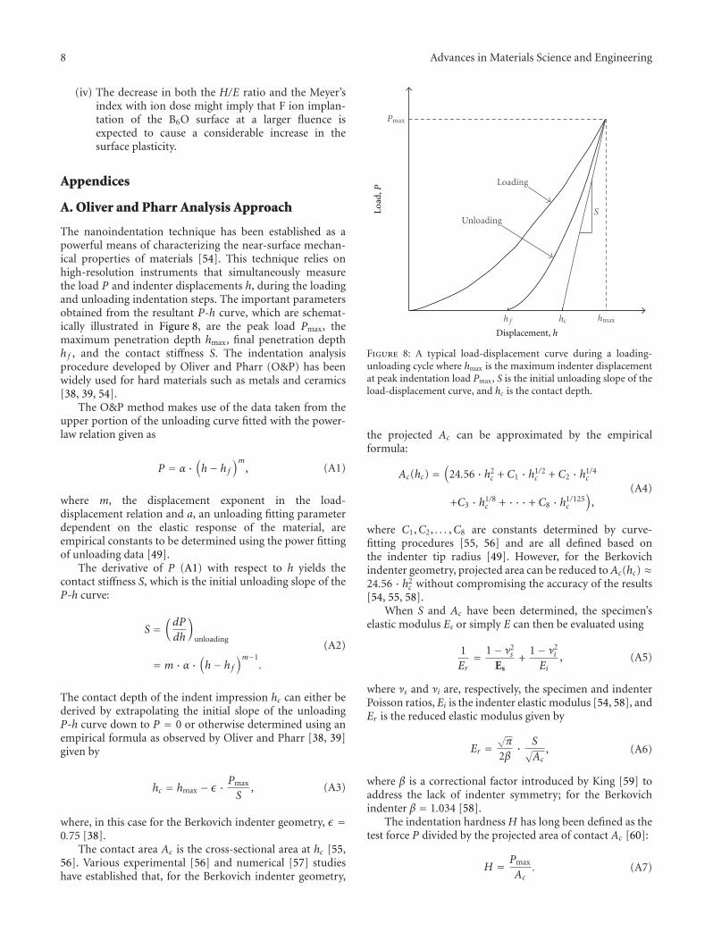
The nanoindentation technique has been established as apowerful means of characterizing the near-surface mechan-ical properties of materials [54]. This technique relies onhigh-resolution instruments that simultaneously measurethe load P and indenter displacements h, during the loadingand unloading indentation steps. The important parametersobtained from the resultant P-h curve, which are schemat-ically illustrated in Figure 8, are the peak load Pmax, themaximum penetration depth hmax, final penetration depthh f , and the contact stiffness S. The indentation analysisprocedure developed by Oliver and Pharr (O&P) has beenwidely used for hard materials such as metals and ceramics[38, 39, 54].
The O&P method makes use of the data taken from theupper portion of the unloading curve fitted with the power-law relation given as
P = α ·(h− h f
)m, (A1)
where m, the displacement exponent in the load-displacement relation and a, an unloading fitting parameterdependent on the elastic response of the material, areempirical constants to be determined using the power fittingof unloading data [49].
The derivative of P (A1) with respect to h yields thecontact stiffness S, which is the initial unloading slope of theP-h curve:
S =(dP
dh
)
unloading
= m · α ·(h− h f
)m−1.
(A2)
The contact depth of the indent impression hc can either bederived by extrapolating the initial slope of the unloadingP-h curve down to P = 0 or otherwise determined using anempirical formula as observed by Oliver and Pharr [38, 39]given by
hc = hmax − ε · Pmax
S, (A3)
where, in this case for the Berkovich indenter geometry, ε =0.75 [38].
The contact area Ac is the cross-sectional area at hc [55,56]. Various experimental [56] and numerical [57] studieshave established that, for the Berkovich indenter geometry,
Pmax
hmaxhch f
Loading
UnloadingSLo
ad,P
Displacement, h
Figure 8: A typical load-displacement curve during a loading-unloading cycle where hmax is the maximum indenter displacementat peak indentation load Pmax, S is the initial unloading slope of theload-displacement curve, and hc is the contact depth.
the projected Ac can be approximated by the empiricalformula:
Ac(hc) =(
24.56 · h2c + C1 · h1/2
c + C2 · h1/4c
+C3 · h1/8c + · · · + C8 · h1/125
c
),
(A4)
where C1,C2, . . . ,C8 are constants determined by curve-fitting procedures [55, 56] and are all defined based onthe indenter tip radius [49]. However, for the Berkovichindenter geometry, projected area can be reduced toAc(hc) ≈24.56 · h2
c without compromising the accuracy of the results[54, 55, 58].
When S and Ac have been determined, the specimen’selastic modulus Es or simply E can then be evaluated using
1Er= 1− ν2
s
Es+
1− ν2i
Ei, (A5)
where νs and νi are, respectively, the specimen and indenterPoisson ratios, Ei is the indenter elastic modulus [54, 58], andEr is the reduced elastic modulus given by
Er =√π
2β· S√
Ac, (A6)
where β is a correctional factor introduced by King [59] toaddress the lack of indenter symmetry; for the Berkovichindenter β = 1.034 [58].
The indentation hardness H has long been defined as thetest force P divided by the projected area of contact Ac [60]:
H = Pmax
Ac. (A7)
Advances in Materials Science and Engineering 9
x: 3.8 µm y: 3.8 µm
2.59 µm2.36 µm
(a) Specimen A
x: 3.3 µm y: 3.3 µm
2.7 µm2.38 µm
(b) Specimen C
x: 4 µmy: 4 µm
2.78 µm2.41 µm
(c) Specimen D
x: 4.4 µmy: 4.4 µm
2.79 µm2.38 µm
(d) Specimen G
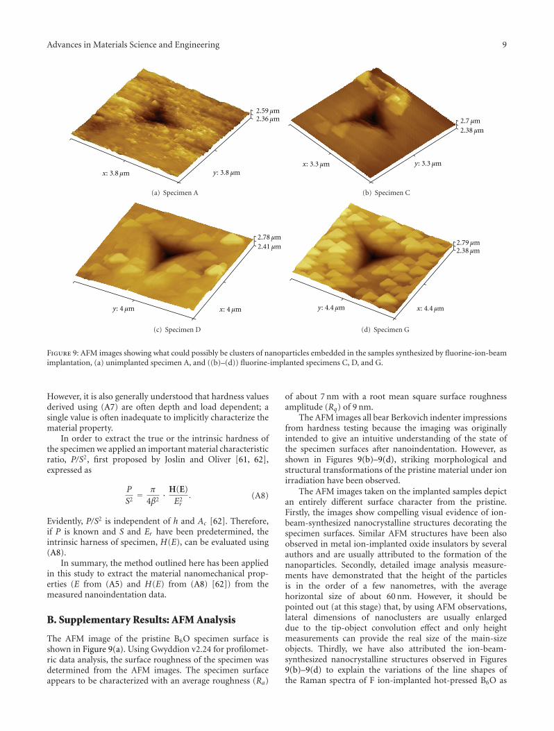
Figure 9: AFM images showing what could possibly be clusters of nanoparticles embedded in the samples synthesized by fluorine-ion-beamimplantation, (a) unimplanted specimen A, and ((b)–(d)) fluorine-implanted specimens C, D, and G.
However, it is also generally understood that hardness valuesderived using (A7) are often depth and load dependent; asingle value is often inadequate to implicitly characterize thematerial property.
In order to extract the true or the intrinsic hardness ofthe specimen we applied an important material characteristicratio, P/S2, first proposed by Joslin and Oliver [61, 62],expressed as
P
S2= π
4β2· H(E)
E2r
. (A8)
Evidently, P/S2 is independent of h and Ac [62]. Therefore,if P is known and S and Er have been predetermined, theintrinsic harness of specimen, H(E), can be evaluated using(A8).
In summary, the method outlined here has been appliedin this study to extract the material nanomechanical prop-erties (E from (A5) and H(E) from (A8) [62]) from themeasured nanoindentation data.
B. Supplementary Results: AFM Analysis
The AFM image of the pristine B6O specimen surface isshown in Figure 9(a). Using Gwyddion v2.24 for profilomet-ric data analysis, the surface roughness of the specimen wasdetermined from the AFM images. The specimen surfaceappears to be characterized with an average roughness (Ra)
of about 7 nm with a root mean square surface roughnessamplitude (Rq) of 9 nm.
The AFM images all bear Berkovich indenter impressionsfrom hardness testing because the imaging was originallyintended to give an intuitive understanding of the state ofthe specimen surfaces after nanoindentation. However, asshown in Figures 9(b)–9(d), striking morphological andstructural transformations of the pristine material under ionirradiation have been observed.
The AFM images taken on the implanted samples depictan entirely different surface character from the pristine.Firstly, the images show compelling visual evidence of ion-beam-synthesized nanocrystalline structures decorating thespecimen surfaces. Similar AFM structures have been alsoobserved in metal ion-implanted oxide insulators by severalauthors and are usually attributed to the formation of thenanoparticles. Secondly, detailed image analysis measure-ments have demonstrated that the height of the particlesis in the order of a few nanometres, with the averagehorizontal size of about 60 nm. However, it should bepointed out (at this stage) that, by using AFM observations,lateral dimensions of nanoclusters are usually enlargeddue to the tip-object convolution effect and only heightmeasurements can provide the real size of the main-sizeobjects. Thirdly, we have also attributed the ion-beam-synthesized nanocrystalline structures observed in Figures9(b)–9(d) to explain the variations of the line shapes ofthe Raman spectra of F ion-implanted hot-pressed B6O as
10 Advances in Materials Science and Engineering
shown in Figure 3 and reference [14]. Fourthly and lastly,the surfaces of the implanted samples appear to be muchsmoother in appearance than those of the pristine sample[63], tentatively suggestive that possible sputtering andother dynamic processes could have influenced the surfacemorphology of the specimen during implantation.
Acknowledgments
The authors are appreciative for the valuable contributionsof O. T. Johnson, M. Herrmann, W. Goosen, J. Neethling,the Nelson Mandela Metropolitan University, and the Centrefor Scientific and Industrial Research’s National Centre forNanostructured Materials. The financial support from theDST/NRF Centre of Excellence in Strong Materials andUniversity of the Witwatersrand Mellon Postgraduate Awardis also gratefully acknowledged.
References
[1] K. J. Kirkby and R. P. Webb, “Ion Implanted Nanostructures,”in Encyclopedia of Nanoscience and Nanotechnology, H. S.Nalwa, Ed., vol. 4, pp. 1–11, American Scientific Publishers,2004.
[2] I. Jain and G. Agarwal, “Ion beam induced surface andinterface engineering,” Surface Science Reports, vol. 66, no. 3-4,pp. 77–172, 2011.
[3] A. L. Stepanov, “Synthesis of silver nanoparticles in dielectricmatrix by ion implantation: a review,” Reviews on AdvancedMaterials Science, vol. 26, no. 1-2, pp. 1–29, 2010.
[4] J. F. Prins, “Modification, doping and devices in implanteddiamond,” in Properties of Natuaral and Synthetic Diamong,chapter 8, pp. 301–341, Academic Press Limited, 1992.
[5] J. Ghatak, B. Satpati, M. Umananda et al., “Characterizationof ion beam induced nanostructures,” Nuclear Instruments andMethods in Physics Research B, vol. 244, no. 1, pp. 45–51, 2006.
[6] D. K. Avasthi and J. C. Pivin, “Ion beam for synthesis andmodification of nanostructures,” Current Science, vol. 98, no.6, pp. 780–792, 2010.
[7] H. Hosono and H. Kawazoe, “Approach to novel crystallineand amorphous oxide materials for optoelectronics by ionimplantation,” Materials Science and Engineering B, vol. 41, no.1, pp. 39–45, 1996.
[8] Y. Shen, X. Li, Z. Wang et al., “Fabrication and thermalevolution of nanoparticles in SiO2 by Zn ion implantation,”Journal of Crystal Growth, vol. 311, no. 21, pp. 4605–4609,2009.
[9] R. MacHaka, R. M. Erasmus, and T. E. Derry, “Formation ofcBN nanocrystals by He+ implantation into hBN,” Diamondand Related Materials, vol. 19, no. 10, pp. 1131–1134, 2010.
[10] I. D. Desnica-Frankovi, K. Furi, U. V. Desnica, M. C. Ridgway,and C. J. Glover, “Structural modifications in amorphousGe produced by ion implantation,” Nuclear Instruments andMethods in Physics Research B, vol. 178, no. 1–4, pp. 192–195,2001.
[11] T. W. H. Oates, L. Ryves, F. A. Burgmann et al., “Ionimplantation induced phase transformation in carbon andboron nitride thin films,” Diamond and Related Materials, vol.14, no. 8, pp. 1395–1401, 2005.
[12] F. Komarov, L. Vlasukova, W. Wesch et al., “Formation of InAsnanocrystals in Si by high-fluence ion implantation,” Nuclear
Instruments and Methods in Physics Research B, vol. 266, no.16, pp. 3557–3564, 2008.
[13] J. I. Onate, F. Alonso, and A. Garcıa, “Improvement oftribological properties by ion implantation,” Thin Solid Films,vol. 317, no. 1-2, pp. 471–476, 1998.
[14] R. Machaka, T. E. Derry, and I. Sigalas, “Nanoindentationhardness of hot-pressed boron suboxide,” Materials Scienceand Engineering A, vol. 528, no. 18, pp. 5778–5783, 2011.
[15] M. Herrmann, H. J. Kleebe, J. Raethel et al., “Field-assisteddensification of superhard B6O materials with Y2O3/Al2O3
addition,” Journal of the American Ceramic Society, vol. 92, no.10, pp. 2368–2372, 2009.
[16] M. Herrmann, J. Raethel, A. Bales, K. Sempf, I. Sigalas, and M.Hoehn, “Liquid phase assisted densification of superhard B6Omaterials,” Journal of the European Ceramic Society, vol. 29, no.12, pp. 2611–2617, 2009.
[17] O. T. Johnson, I. Sigalas, E. N. Ogunmuyiwa, H. J. Kleebe, M.M. Muller, and M. Herrmann, “Boron suboxide materials withCo sintering additives,” Ceramics International, vol. 36, no. 6,pp. 1767–1771, 2010.
[18] A. Andrews, M. Herrmann, T. C. Shabalala, and I. Sigalas,“Liquid phase assisted hot pressing of boron suboxide-materials,” Journal of the European Ceramic Society, vol. 28, no.8, pp. 1613–1621, 2008.
[19] A. Andrews, Development of boron suboxide composites withimproved toughness, Ph.D. thesis, School of Chemical andMetallurgical Engineering, University of the Witwatersrand0,2009.
[20] C. S. Freemantle, The wear studies of boron suboxide basedcutting tool materials in machining applications, M.S. thesis,School of Chemical and Metallurgical Engineering, Universityof the Witwatersrand, 2010.
[21] R. Machaka, B. W. Mwakikunga, E. Manikandan, T. E.Derry, and I. Sigalas, “Raman spectrum of hot-pressed boronsuboxide,” Advanced Materials Letters, vol. 2, p. 68, 2011.
[22] J. Lowther, Personal Communication, 2009.
[23] J. F. Prins, “Ion-implanted structures and doped layers indiamond,” Materials Science Reports, vol. 7, no. 7-8, pp. 271–364, 1992.
[24] J. Ziegler, SRIM2010 (Software package), 2010, http://www.srim.org/.
[25] P. Klapetek, D. Necas, and C. Anderson, Gwyddion v2.24(Software package), 2010, http://gwyddion.net/.
[26] R. Machaka, B. W. Mwakikunga, E. Manikandan, T. E. Derry,and I. Sigalas, “Structural transformation in ultrahard B6Oinduced by F-ion implantation studied by micro-Ramanspectroscopy,” Unpublished.
[27] O. T. Johnson, Improvement on the mechanical properties ofboron suboxide (B60) based composites using other compoundsas second phase, M.S. thesis, School of Chemical and Metallur-gical Engineering, University of the Witwatersrand, 2009.
[28] O. T. Johnson, I. Sigalas, and M. Herrmann, “Microstructureand interfacial reactions between B6O and (Ni, Co) couples,”Ceramics International, vol. 36, no. 8, pp. 2401–2406, 2010.
[29] Z. Wang, Y. Zhao, P. Lazor, H. Annersten, and S. K. Saxena, “Insitu pressure Raman spectroscopy and mechanical stability ofsuperhard boron suboxide,” Applied Physics Letters, vol. 86, no.4, Article ID 041911, pp. 1–41911, 2005.
[30] H. Werheit and U. Kuhlmann, “FTIR and FT Raman spectraof B6O,” Journal of Solid State Chemistry, vol. 133, no. 1, pp.260–263, 1997.
Advances in Materials Science and Engineering 11
[31] S. Yu, Y. Ji, T. Li et al., “Nanofilms with clusters of boronsuboxide and their infrared absorption,” Solid State Commu-nications, vol. 115, no. 6, pp. 307–311, 2000.
[32] V. L. Solozhenko, O. O. Kurakevych, and P. Bouvier, “Firstand second-order Raman scattering of B6O,” Journal of RamanSpectroscopy, vol. 40, no. 8, pp. 1078–1081, 2009.
[33] C. S. R. Rao, S. Sundaram, R. L. Schmidt, and J. Comas,“Study of ion-implantation damage in GaAs:Be and InP:Beusing Raman scattering,” Journal of Applied Physics, vol. 54,no. 4, pp. 1808–1815, 1983.
[34] S. S. Kumar, M. A. Khadar, S. K. Dhara, T. R. Ravindran, andK. G. M. Nair, “Photoluminescence and Raman studies of ZnSnanoparticles implanted with Cu+ ions,” Nuclear Instrumentsand Methods in Physics Research B, vol. 251, no. 2, pp. 435–440,2006.
[35] A. K. Arora, M. Rajalakshmi, T. R. Ravindran, and V.Sivasubramanian, “Raman spectroscopy of optical phononconfinement in nanostructured materials,” Journal of RamanSpectroscopy, vol. 38, no. 6, pp. 604–617, 2007.
[36] M. Nastasi and J. W. Mayer, Ion Implantation and Synthesis ofMaterials, Springer, Berlin, Germany, 2006.
[37] W. C. Oliver and G. M. Pharr, “Improved technique fordetermining hardness and elastic modulus using load anddisplacement sensing indentation experiments,” Journal ofMaterials Research, vol. 7, no. 6, pp. 1564–1580, 1992.
[38] W. C. Oliver and G. M. Pharr, “Measurement of hardnessand elastic modulus by instrumented indentation: advancesin understanding and refinements to methodology,” Journal ofMaterials Research, vol. 19, no. 1, pp. 3–20, 2004.
[39] G. M. Pharr and A. Bolshakov, “Understanding nanoindenta-tion unloading curves,” Journal of Materials Research, vol. 17,no. 10, pp. 2660–2671, 2002.
[40] X. Jiao, H. Jin, F. Liu et al., “Synthesis of boron suboxide (B6O)with ball milled boron oxide (B2O3) under lower pressure andtemperature,” Journal of Solid State Chemistry, vol. 183, no. 7,pp. 1697–1703, 2010.
[41] S. R. Jian, G. J. Chen, and J. Y. Juang, “Nanoindentation-induced phase transformation in (1 1 0)-oriented Si single-crystals,” Current Opinion in Solid State and Materials Science,vol. 14, no. 3-4, pp. 69–74, 2010.
[42] C. A. Schuh, “Nanoindentation studies of materials,” MaterialsToday, vol. 9, no. 5, pp. 32–40, 2006.
[43] J. G. Wang, B. W. Choi, T. G. Nieh, and C. T. Liu,“Crystallization and nanoindentation behavior of a bulk Zr-Al-Ti-Cu-Ni amorphous alloy,” Journal of Materials Research,vol. 15, no. 3, pp. 798–807, 2000.
[44] N. Laidania, A. Miotello, and J. Perriere, “Chemical, mechani-cal and electrical properties of CNx-films produced by reactivesputtering and N+-implantation in carbon films,” AppliedSurface Science, vol. 99, no. 4, pp. 273–284, 1996.
[45] A. Leyland and A. Matthews, “On the significance of the H/Eratio in wear control: a nanocomposite coating approach tooptimised tribological behaviour,” Wear, vol. 246, no. 1-2, pp.1–11, 2000.
[46] P. Lemoine, J. P. Quinn, P. Maguire, and J. A. McLaughlin,“Comparing hardness and wear data for tetrahedral amor-phous carbon and hydrogenated amorphous carbon thinfilms,” Wear, vol. 257, no. 5-6, pp. 509–522, 2004.
[47] T. Oberle, “Properties influencing the wear of metals,” Journalof Metrologia, vol. 3, p. 438, 1951.
[48] J. Gong, J. Wu, and Z. Guan, “Analysis of the indentationsize effect on the apparent hardness for ceramics,” MaterialsLetters, vol. 38, no. 3, pp. 197–201, 1999.
[49] J. Gong, H. Miao, and Z. Peng, “A new function for thedescription of the nanoindentation unloading data,” ScriptaMaterialia, vol. 49, no. 1, pp. 93–97, 2003.
[50] O. Sahin, O. Uzun, U. Kolemen, and N. Ucar, “Mechanicalcharacterization for β-Sn single crystals using nanoindenta-tion tests,” Materials Characterization, vol. 59, no. 4, pp. 427–434, 2008.
[51] O. Sahin, O. Uzun, M. Sopicka-Lizer, H. Gocmez, and U.Kolemen, “Dynamic hardness and elastic modulus calculationof porous SiAlON ceramics using depth-sensing indentationtechnique,” Journal of the European Ceramic Society, vol. 28,no. 6, pp. 1235–1242, 2008.
[52] K. Sangwal, “On the reverse indentation size effect andmicrohardness measurement of solids,” Materials Chemistryand Physics, vol. 63, no. 2, pp. 145–152, 2000.
[53] H. Li and R. C. Bradt, “The indentation load/size effect andthe measurement of the hardness of vitreous silica,” Journal ofNon-Crystalline Solids, vol. 146, pp. 197–212, 1992.
[54] A. Fischer-Cripps, Nanoindentation, Springer, New York, NY,USA, 2nd edition, 2004.
[55] J. Gong, H. Miao, and Z. Peng, “Analysis of the nanoinden-tation data measured with a Berkovich indenter for brittlematerials: effect of the residual contact stress,” Acta Materialia,vol. 52, no. 3, pp. 785–793, 2004.
[56] J. Gong, H. Miao, and Z. Peng, “On the contact area fornanoindentation tests with Berkovich indenter: case study onsoda-lime glass,” Materials Letters, vol. 58, no. 7-8, pp. 1349–1353, 2004.
[57] K. D. Bouzakis and N. Michailidis, “Indenter surface areaand hardness determination by means of a FEM-supportedsimulation of nanoindentation,” Thin Solid Films, vol. 494, no.1-2, pp. 155–160, 2006.
[58] N. Janakiraman and F. Aldinger, “Indentation analysis ofelastic and plastic deformation of precursor-derived Si-C-Nceramics,” Journal of the European Ceramic Society, vol. 30, no.3, pp. 775–785, 2010.
[59] R. B. King, “Elastic analysis of some punch problems for a lay-ered medium,” International Journal of Solids and Structures,vol. 23, no. 12, pp. 1657–1664, 1987.
[60] B. Mott, Microindentation Hardness Testing, Butterworths,London, UK, 1956.
[61] D. L. Joslin and W. C. Oliver, “New method for analyzingdata from continuos depth-sensing microindentation tests,”Journal of Materials Research, vol. 5, no. 1, pp. 123–126, 1990.
[62] X. Y. Zhou, Z. D. Jiang, H. R. Wang, and Q. Zhu, “A methodto extract the intrinsic mechanical properties of soft metallicthin films based on nanoindentation continuous stiffnessmeasurement technique,” Journal of Physics, vol. 48, no. 1,article 204, pp. 1096–1101, 2006.
[63] E. H. Lee, M. B. Lewis, P. J. Blau, and L. K. Mansur, “Improvedsurface properties of polymer materials by multiple ion beamtreatment,” Journal of Materials Research, vol. 6, no. 3, pp. 610–628, 1991.

Submit your manuscripts athttp://www.hindawi.com
ScientificaHindawi Publishing Corporationhttp://www.hindawi.com Volume 2014
CorrosionInternational Journal of
Hindawi Publishing Corporationhttp://www.hindawi.com Volume 2014
Polymer ScienceInternational Journal of
Hindawi Publishing Corporationhttp://www.hindawi.com Volume 2014
Hindawi Publishing Corporationhttp://www.hindawi.com Volume 2014
CeramicsJournal of
Hindawi Publishing Corporationhttp://www.hindawi.com Volume 2014
CompositesJournal of
NanoparticlesJournal of
Hindawi Publishing Corporationhttp://www.hindawi.com Volume 2014
Hindawi Publishing Corporationhttp://www.hindawi.com Volume 2014
International Journal of
Biomaterials
Hindawi Publishing Corporationhttp://www.hindawi.com Volume 2014
NanoscienceJournal of
TextilesHindawi Publishing Corporation http://www.hindawi.com Volume 2014
Journal of
NanotechnologyHindawi Publishing Corporationhttp://www.hindawi.com Volume 2014
Journal of
CrystallographyJournal of
Hindawi Publishing Corporationhttp://www.hindawi.com Volume 2014
The Scientific World JournalHindawi Publishing Corporation http://www.hindawi.com Volume 2014
Hindawi Publishing Corporationhttp://www.hindawi.com Volume 2014
CoatingsJournal of
Advances in
Materials Science and EngineeringHindawi Publishing Corporationhttp://www.hindawi.com Volume 2014
Smart Materials Research
Hindawi Publishing Corporationhttp://www.hindawi.com Volume 2014
Hindawi Publishing Corporationhttp://www.hindawi.com Volume 2014
MetallurgyJournal of
Hindawi Publishing Corporationhttp://www.hindawi.com Volume 2014
BioMed Research International
MaterialsJournal of
Hindawi Publishing Corporationhttp://www.hindawi.com Volume 2014
Nano
materials
Hindawi Publishing Corporationhttp://www.hindawi.com Volume 2014
Journal ofNanomaterials