mechanism feasibility design task - github pages · design & manufacture 2 –mechanism...
TRANSCRIPT

Mechanism Feasibility Design Task
Dr. James Gopsill
2017
1Design & Manufacture 2 – Mechanism Feasibility Design
Lecture 5

Contents
1. Last Week
2. Types of Gear
3. Gear Definitions
4. Gear Forces
5. Multi-Stage Gearbox Example
6. Gearbox Design Report Section
7. This Weeks Task
2
2017
Design & Manufacture 2 – Mechanism Feasibility Design
Lecture 5

Last Week
Systems Modelling in Simulink
• Demo: Stopping the simulation at a specific point
• Demo: Adding damping to a system
• Demo: Four-bar mechanism
Where you should be at:
• Mechanism modelled in Simulink
• Evaluated a range of motors, gear ratios and level of damping
3
2017
Product Design Specification
Concept Design
Concept Selection
Deployment Modelling
Motor, Gear Ratio & Damping Selection
Gearbox Design
Stage-Gate
Design & Manufacture 2 – Mechanism Feasibility Design
Lecture 5

Types of Gear
4
2017
Design & Manufacture 2 – Mechanism Feasibility Design
Lecture 5

Spur
5
2017
• Applications
• Low/Moderate speed environments (Pitch Line Velocity < 25ms-1)
• Engines, Power Plants, Fuel Pumps, Washing Machines, Rack & Pinion mechanisms
• Pros
• Can transmit large amounts of power (50,000kW)
• High Reliability
• Constant Velocity Ratio
• Simple to Manufacture
• Cons
• Initial contact is across entire tooth width leading to higher stresses
• Noise at high speeds
• Can’t transfer power between non-parallel shafts
Design & Manufacture 2 – Mechanism Feasibility Design
Lecture 5

Helical
6
2017
• Applications
• High speed environments (> 25ms-1)
• Automotive industry
• Elevators, conveyors
• Pros
• Smoother running compared to spur
• Higher load transfer per width of gear compared to spur
• Typically longer maintenance cycles
• Cons
• Thrust bearings required to counter axial forces
• Greater heat generation compared to spur due to gear mating
• Typically less efficient than spur gears
Design & Manufacture 2 – Mechanism Feasibility Design
Lecture 5

Herringbone
7
2017
• Applications
• 3D Printers
• Heavy Machinery
• Pros
• Smoother power transmission
• Resistant to operation disruption from missing/damaged teeth
• Cons
• Difficult to manufacture and hence more expensive
Design & Manufacture 2 – Mechanism Feasibility Design
Lecture 5

Epicyclic
8
2017
• Applications
• Lathes, hoists, pulley blocks, watches
• Automatic Transmissions
• Hybrid Vehicles (engine and motor)
• Pros
• Higher efficiency
• Higher power density
• Accurate gearing
• Packaging (Achieve higher ratios in the same area)
• In-line input-output shafts
• Cons
• Loud operation
• High accuracy manufacturing required to ensure equal load sharing
Design & Manufacture 2 – Mechanism Feasibility Design
Lecture 5

Worm
9
2017
• Applications
• Elevators, hoists
• Packaging equipment
• Rock Crushers
• Tuning Instruments
• Pros
• Near silent and smooth operation
• Self-locking
• Occupy less space of equivalent spur gear ratio
• High velocity ratio can be attained within a single step (approx. 100:1)
• Absorb shock loading
• Cons
• Expensive to manufacture
• Higher power losses compared
• Greater heat generation due to increased teeth contact
Design & Manufacture 2 – Mechanism Feasibility Design
Lecture 5

Bevel
10
2017
• Applications
• Differential drives (e.g. vehicles)
• Hand drills
• Assembly machinery
• Pros
• Change direction of power transmission
• Cons
• Difficult to manufacture
• Precision mountings
Design & Manufacture 2 – Mechanism Feasibility Design
Lecture 5

Car Convertible Roof
• Worm Gear to Multi-Stage Gearbox
• We will solely design a multi-stage spur/helical gear set
11
2017
Design & Manufacture 2 – Mechanism Feasibility Design
Lecture 5

Gear Definitions
12
2017
Design & Manufacture 2 – Mechanism Feasibility Design
Lecture 5

Gear Definitions
13
2017
• Pinion
• Smaller Gear
• (𝑛, 𝑑) = number of teeth, PCD
• Wheel
• Larger Gear
• (𝑁,𝐷) = number of teeth, PCD
Design & Manufacture 2 – Mechanism Feasibility Design
Lecture 5

Gear Definitions
14
2017
• Velocity Ratio
𝑉𝑅 =𝑁
𝑛=𝐷
𝑑• Examples
• Pinion has 20 teeth and Wheel has 40
𝑉𝑅 =40
20= 2
• If connected to a wheel of 60 and pinion of 20
𝑉𝑅 =40
20×60
20= 6
Design & Manufacture 2 – Mechanism Feasibility Design
Lecture 5

Gear Definitions
15
2017
• Limiting Velocity Ratios
• Pinion and wheel efficiency (𝜂)
95-96% per stage
Type of gear pair VR lower limit VR upper limit
Worm and wheel 5 60
All others 1 5
Design & Manufacture 2 – Mechanism Feasibility Design
Lecture 5

Gear Definitions
• Module (𝑀)𝑀 =
𝑑
𝑛=𝐷
𝑁
• Addendum (𝐴)𝐴 = 𝑀
• Dedendum (𝐵)𝐵 = 1.25𝑀
• Tooth depth𝐴 + 𝐵 = 2.25𝑀
16
2017
Design & Manufacture 2 – Mechanism Feasibility Design
Lecture 5
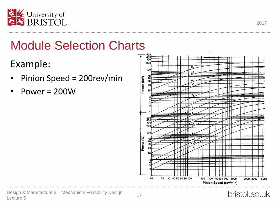
Module Selection Charts
Example:
• Pinion Speed = 200rev/min
• Power = 200W
17
2017
Design & Manufacture 2 – Mechanism Feasibility Design
Lecture 5

Module Selection Charts
Example:
• Pinion Speed = 200rev/min
• Power = 200W
Answer:
• Modules > 2.5
18
2017
Design & Manufacture 2 – Mechanism Feasibility Design
Lecture 5

Gear Definitions
• Face Widths• Relatively light loads (W = 8𝑀)
• Moderate loads (W = 10𝑀)
• Heavy loads (W = 12𝑀)
19
2017
Design & Manufacture 2 – Mechanism Feasibility Design
Lecture 5

Gear Definition - Teeth Hunting
• Transmission forces are often cyclical
• Some teeth may experience higher forces than others
• Having the teeth hunt distributes the cyclic loading across all the teeth in gear
• Uniform wear
• Also, maximise the number of cycles before two damaged gears will mesh with one another
20
2017
Design & Manufacture 2 – Mechanism Feasibility Design
Lecture 5

Gear Definition - Teeth Hunting
Determining Hunting Tooth Frequencies
1. Calculate the common factors (𝐶𝐹) between the teeth
2. Looking for the highest common factor (12)
3. Hunting Tooth Frequency (𝐻𝑇𝐹)
𝐻𝑇𝐹 =𝐺𝑀𝐹 × 𝐶𝐹
𝑛 × 𝑁
𝐺𝑀𝐹 = gear mesh frequency
21
2017
Design & Manufacture 2 – Mechanism Feasibility Design
Lecture 5

Gear Definition - Teeth Hunting
Determining Hunting Tooth Frequencies
22
2017
Example:
2000rpm, 24 pinion teeth, 84 wheel teeth
Design & Manufacture 2 – Mechanism Feasibility Design
Lecture 5

Gear Definition - Teeth Hunting
23
2017
Example:
2000rpm, 24 pinion teeth, 84 wheel teeth
Pinion (24 Teeth) Wheel (84 Teeth)
1 x 242 x 123 x 84 x 6
1 x 842 x 423 x 284 x 216 x 147 x 12
Design & Manufacture 2 – Mechanism Feasibility Design
Lecture 5
Determining Hunting Tooth Frequencies
1. Calculate the common factors (𝐶𝐹) between the teeth

Gear Definition - Teeth Hunting
24
2017
Example:
2000rpm, 24 pinion teeth, 84 wheel teeth
Design & Manufacture 2 – Mechanism Feasibility Design
Lecture 5
Determining Hunting Tooth Frequencies
1. Calculate the common factors (𝐶𝐹) between the teeth
2. Looking for the highest common factor (=12 in this case)
Pinion (24 Teeth) Wheel (84 Teeth)
1 x 242 x 123 x 84 x 6
1 x 842 x 423 x 284 x 216 x 147 x 12

Gear Definition - Teeth Hunting
Determining Hunting Tooth Frequencies
1. Calculate the common factors (𝐶𝐹) between the teeth
2. Looking for the highest common factor (=12 in this case)
3. Hunting Tooth Frequency (𝐻𝑇𝐹)
𝐻𝑇𝐹 =𝐺𝑀𝐹 × 𝐶𝐹
𝑛 × 𝑁
Where 𝐺𝑀𝐹 is the gear mesh frequency (𝐺𝑀𝐹)
𝐺𝑀𝐹 = 𝑟𝑝𝑚 × 𝑛
25
2017
Example:
2000rpm, 24 pinion teeth, 84 wheel teeth
(2000 × 24) × 12
24 × 84=48000 × 12
24 × 84= 285.7 clashes per min
Design & Manufacture 2 – Mechanism Feasibility Design
Lecture 5
Pinion (24 Teeth) Wheel (84 Teeth)
1 x 242 x 123 x 84 x 6
1 x 842 x 423 x 284 x 216 x 147 x 12

Gear Forces
26
2017
Design & Manufacture 2 – Mechanism Feasibility Design
Lecture 5
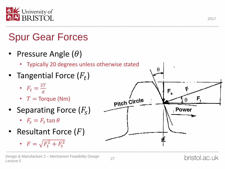
Spur Gear Forces
27
2017
• Pressure Angle (𝜃)• Typically 20 degrees unless otherwise stated
• Tangential Force (𝐹𝑡)
• 𝐹𝑡 =2𝑇
𝑑
• 𝑇 = Torque (Nm)
• Separating Force (𝐹𝑠)• 𝐹𝑠 = 𝐹𝑡 tan𝜃
• Resultant Force (𝐹)
• 𝐹 = 𝐹𝑡2 + 𝐹𝑠
2
Design & Manufacture 2 – Mechanism Feasibility Design
Lecture 5

Helical Gear Forces
28
2017
• Tangential Force (𝐹𝑡) • Same as for Spur
• 𝐹𝑡 =2𝑇
𝑑
• 𝑇 = Torque (Nm)
• Separating Force (𝐹𝑠)
• 𝐹𝑠 =𝐹𝑡 tan 𝜃
cos 𝛼, 𝛼 = helix angle (assume 20 degrees unless otherwise stated)
• Axial Force (𝐹𝑎)• 𝐹𝑎 = 𝐹𝑡 tan𝛼
• Resultant Force (𝐹)
• 𝐹 = 𝐹𝑡2 + 𝐹𝑠
2
Design & Manufacture 2 – Mechanism Feasibility Design
Lecture 5

Example Gearbox
29
2017
Design & Manufacture 2 – Mechanism Feasibility Design
Lecture 5

Three Stage Gearbox
Design Example
30
2017
A three-stage spur gearbox is to provide a 1:125 total gear ratio for a motor providing 500W @ 1000 rev/min.
Gear Stage 1 2 3
VR
Combined VR
Module
Pinion Teeth
Pinion PCD (mm)
Wheel Teeth
Wheel PCD (mm)
Hunting Tooth Frequency
Efficiency
Pinion Speed (rev/min)
Wheel Speed (rev/min)
Pinion Torque (Nm)
Wheel Torque (Nm)
Pinion Forces
Tangential Force (kN)
Separating Force (kN)
Resultant Force (kN)
Design & Manufacture 2 – Mechanism Feasibility Design
Lecture 5

Three Stage Gearbox
Design Example
31
2017
A three-stage spur gearbox is to provide a 1:125 total gear ratio for a motor providing 500W @ 1000 rev/min.
Gear Stage 1 2 3
VR
Combined VR
Module
Pinion Teeth
Pinion PCD (mm)
Wheel Teeth
Wheel PCD (mm)
Hunting Tooth Frequency
Efficiency 0.95 (1) 0.95 (1) 0.95 (1)
Pinion Speed (rev/min) 1000.00 (1)
Wheel Speed (rev/min)
Pinion Torque (Nm) 104.70 (1)
Wheel Torque (Nm)
Pinion Forces
Tangential Force (kN)
Separating Force (kN)
Resultant Force (kN)
Design & Manufacture 2 – Mechanism Feasibility Design
Lecture 5
1. Put in the initial conditions

Three Stage Gearbox
Design Example
32
2017
A three-stage spur gearbox is to provide a 1:125 total gear ratio for a motor providing 500W @ 1000 rev/min.
Gear Stage 1 2 3
VR 5.00 (2) 5.00 (2) 5.00 (2)
Combined VR 5.00 (2) 25.00 (2) 125.00 (2)
Module
Pinion Teeth
Pinion PCD (mm)
Wheel Teeth
Wheel PCD (mm)
Hunting Tooth Frequency
Efficiency 0.95 (1) 0.95 (1) 0.95 (1)
Pinion Speed (rev/min) 1000.00 (1)
Wheel Speed (rev/min)
Pinion Torque (Nm) 104.70 (1)
Wheel Torque (Nm)
Pinion Forces
Tangential Force (kN)
Separating Force (kN)
Resultant Force (kN)
Design & Manufacture 2 – Mechanism Feasibility Design
Lecture 5
1. Put in the initial conditions
2. Make an initial guess at the VR for
each stage to generate the correct
combined VR

Three Stage Gearbox
Design Example
33
2017
A three-stage spur gearbox is to provide a 1:125 total gear ratio for a motor providing 500W @ 1000 rev/min.
Gear Stage 1 2 3
VR 5.00 (2) 5.00 (2) 5.00 (2)
Combined VR 5.00 (2) 25.00 (2) 125.00 (2)
Module 2.00 (3)
Pinion Teeth
Pinion PCD (mm)
Wheel Teeth
Wheel PCD (mm)
Hunting Tooth Frequency
Efficiency 0.95 (1) 0.95 (1) 0.95 (1)
Pinion Speed (rev/min) 1000.00 (1)
Wheel Speed (rev/min)
Pinion Torque (Nm) 104.70 (1)
Wheel Torque (Nm)
Pinion Forces
Tangential Force (kN)
Separating Force (kN)
Resultant Force (kN)
Design & Manufacture 2 – Mechanism Feasibility Design
Lecture 5
1. Put in the initial conditions
2. Make an initial guess at the VR for
each stage to generate the correct
combined VR
3. Determine Module

Three Stage Gearbox
Design Example
34
2017
A three-stage spur gearbox is to provide a 1:125 total gear ratio for a motor providing 500W @ 1000 rev/min.
Gear Stage 1 2 3
VR 5.00 (2) 5.00 (2) 5.00 (2)
Combined VR 5.00 (2) 25.00 (2) 125.00 (2)
Module 2.00 (3)
Pinion Teeth 19.00 (4)
Pinion PCD (mm) 38.00 (4)
Wheel Teeth 95.00 (4)
Wheel PCD (mm) 190.00 (4)
Hunting Tooth Frequency 200.00 (4)
Efficiency 0.95 (1) 0.95 (1) 0.95 (1)
Pinion Speed (rev/min) 1000.00 (1)
Wheel Speed (rev/min)
Pinion Torque (Nm) 104.70 (1)
Wheel Torque (Nm)
Pinion Forces
Tangential Force (kN)
Separating Force (kN)
Resultant Force (kN)
Design & Manufacture 2 – Mechanism Feasibility Design
Lecture 5
1. Put in the initial conditions
2. Make an initial guess at the VR for
each stage to generate the correct
combined VR
3. Determine Module
4. Calculate Pinion/Wheel PCDs &
Hunting Tooth Frequency

Three Stage Gearbox
Design Example
35
2017
A three-stage spur gearbox is to provide a 1:125 total gear ratio for a motor providing 500W @ 1000 rev/min.
Gear Stage 1 2 3
VR 5.00 (2) 5.00 (2) 5.00 (2)
Combined VR 5.00 (2) 25.00 (2) 125.00 (2)
Module 2.00 (3)
Pinion Teeth 19.00 (4)
Pinion PCD (mm) 38.00 (4)
Wheel Teeth 95.00 (4)
Wheel PCD (mm) 190.00 (4)
Hunting Tooth Frequency 200.00 (4)
Efficiency 0.95 (1) 0.95 (1) 0.95 (1)
Pinion Speed (rev/min) 1000.00 (1)
Wheel Speed (rev/min) 200.00 (5)
Pinion Torque (Nm) 104.70 (1) 497.33 (5)
Wheel Torque (Nm) 497.33 (5)
Pinion Forces
Tangential Force (kN)
Separating Force (kN)
Resultant Force (kN)
Design & Manufacture 2 – Mechanism Feasibility Design
Lecture 5
1. Put in the initial conditions
2. Make an initial guess at the VR for
each stage to generate the correct
combined VR
3. Determine Module
4. Calculate Pinion/Wheel PCDs &
Hunting Tooth Frequency
5. Wheel Speed and Torques• Note: Efficiency loss

Three Stage Gearbox
Design Example
36
2017
A three-stage spur gearbox is to provide a 1:125 total gear ratio for a motor providing 500W @ 1000 rev/min.
Gear Stage 1 2 3
VR 5.00 (2) 5.00 (2) 5.00 (2)
Combined VR 5.00 (2) 25.00 (2) 125.00 (2)
Module 2.00 (3)
Pinion Teeth 19.00 (4)
Pinion PCD (mm) 38.00 (4)
Wheel Teeth 95.00 (4)
Wheel PCD (mm) 190.00 (4)
Hunting Tooth Frequency 200.00 (4)
Efficiency 0.95 (1) 0.95 (1) 0.95 (1)
Pinion Speed (rev/min) 1000.00 (1)
Wheel Speed (rev/min) 200.00 (5)
Pinion Torque (Nm) 104.70 (1) 497.33 (5)
Wheel Torque (Nm) 497.33 (5)
Pinion Forces
Tangential Force (kN) 5.51 (6)
Separating Force (kN) 2.01 (6)
Resultant Force (kN) 5.86 (6)
Design & Manufacture 2 – Mechanism Feasibility Design
Lecture 5
1. Put in the initial conditions
2. Make an initial guess at the VR for
each stage to generate the correct
combined VR
3. Determine Module
4. Calculate Pinion/Wheel PCDs &
Hunting Tooth Frequency
5. Wheel Speed and Torques• Note: Efficiency loss
6. Pinion & Wheel Forces

Three Stage Gearbox
Design Example
37
2017
A three-stage spur gearbox is to provide a 1:125 total gear ratio for a motor providing 500W @ 1000 rev/min.
Gear Stage 1 2 3
VR 5.00 (2) 5.00 (2) 5.00 (2)
Combined VR 5.00 (2) 25.00 (2) 125.00 (2)
Module 2.00 (3)
Pinion Teeth 19.00 (4)
Pinion PCD (mm) 38.00 (4)
Wheel Teeth 95.00 (4)
Wheel PCD (mm) 190.00 (4)
Hunting Tooth Frequency 200.00 (4)
Efficiency 0.95 (1) 0.95 (1) 0.95 (1)
Pinion Speed (rev/min) 1000.00 (1)
Wheel Speed (rev/min) 200.00 (5)
Pinion Torque (Nm) 104.70 (1) 497.33 (5)
Wheel Torque (Nm) 497.33 (5)
Pinion Forces
Tangential Force (kN) 5.51 (6)
Separating Force (kN) 2.01 (6)
Resultant Force (kN) 5.86 (6)
1. Put in the initial conditions
2. Make an initial guess at the VR for
each stage to generate the correct
combined VR
3. Determine Module
4. Calculate Pinion/Wheel PCDs &
Hunting Tooth Frequency
5. Wheel Speed and Torques• Note: Efficiency loss
6. Pinion & Wheel Forces
7. Repeat Steps 3-6 for the next stages
Design & Manufacture 2 – Mechanism Feasibility Design
Lecture 5

Gearbox Design
Design Report
• Gearbox Design• Discuss the process you have taken to design the gearbox
• Compare a spur and helical gearbox that meets your criteria (not just gear ratio but also your PDS)
• Rationale behind your chosen design
• Gear arrangement and space optimisation
• Could perform checks on minimum shaft sizes & bearings
38
2017
Design & Manufacture 2 – Mechanism Feasibility Design
Lecture 5
This Week
• Generate an initial spur and helical gear set to drive your mechanism
• Select type and refine gears
• Evaluate against forces, packaging and suitability for the application
• You may have to compromise on your ideal gear ratio from your deployment modelling
• Make sure you record you rationale
39
2017
Design & Manufacture 2 – Mechanism Feasibility Design
Lecture 5

Happy Easter
40
2017
Design & Manufacture 2 – Mechanism Feasibility Design
Lecture 5